Article

Study on High Efficiency Control of Four-Switch Buck-Boost Converter Based on Whale Migration Optimization Algorithm

College of Electrical and Information Engineering, Beihua University, Jilin 132021, China
*
Author to whom correspondence should be addressed.
Energies 2025, 18(11), 2807; https://doi.org/10.3390/en18112807
Submission received: 16 April 2025 / Revised: 23 May 2025 / Accepted: 24 May 2025 / Published: 28 May 2025

Abstract

:
With the growing demand for high-efficiency DC-DC converters with a wide input voltage range for wireless power transmission, four-switch boost converters (FSBBs) are attracting attention due to their low current stress and flexible mode switching characteristics. However, their complex operating modes and nonlinear dynamic characteristics lead to high switching losses and limited efficiency of the system under conventional control. In this paper, an optimization algorithm is combined with the multi-mode control of an FSBB converter for the first time, and a combined optimization and voltage closed-loop control strategy based on the Whale Migration Algorithm (WMA) is proposed. Under the four-mode operation conditions of the FSBB converter, the duty cycle and phase shift parameters of the switching devices are dynamically adjusted by optimizing the values to maximize the efficiency under different operation conditions, with the premise of achieving zero-voltage switching (ZVS) and the optimization objective of minimizing the inductor current as much as possible. Simulation results show that the proposed FSBB switching control strategy combined with the WMA algorithm improves the efficiency significantly over a wide voltage range (120–480 V) and under variable load conditions, and the transfer efficiency is improved by about 1.19% compared with that of the traditional three-mode control, and the maximum transfer efficiency is 99.34%, which verifies the validity and feasibility of the proposed strategy and provides a new approach to the high-efficiency control and application of FSBB converters.

1. Introduction

Wireless power transfer (WPT) technology has been widely used in consumer electronics, electric vehicles, and implantable medical devices due to the flexibility and safety of its contactless power supply. However, variations in coil offset and transmission distance can lead to large fluctuations in the input voltage of the coil receiver DC chopper circuit; in battery charging scenarios, load variations require that the DC chopper circuit be able to regulate the output voltage over a wide range. In response to the above challenges, FSBB converters have attracted attention due to their wide-ranging voltage regulation capability and low voltage stress. However, their diverse operating modes and nonlinear dynamic characteristics make it difficult to find an effective control strategy to utilize their advantages. Their complex switching characteristics, coupled with variable application environments, make it even more difficult to maintain an efficient output.
For this reason, many research studies have been performed. Article [1] adopts a single-mode control method, which equates the FSBB converter to a Buck-Boost topology, and makes the switches in diagonal positions turn on and off at the same time in one cycle to realize the voltage conversion under single-variable control, which is simpler and easier to realize in terms of the control logic, and does not involve the problem of switching back and forth between switching modes; however, during the converter operation, the four switches need to be switched frequently, which makes the switching loss high and the efficiency low. Article [2] proposes an improved single-mode control method, in which the duty cycle of the two tubes on the input side is set as a fixed value, and the duty cycle of the two tubes on the output side is controlled in real time, which has the advantage of effectively reducing the inductor current ripple at extreme Buck-Boost ratios, but the Buck-Boost ratio is limited by the preset fixed duty cycle in this control method, which narrows down the scope of application. Article [3] proposes a dual-mode control strategy, where the FSBB operates in Boost or Buck mode according to the actual working conditions, which solves the problem of the limited Boost/Buck ratio, but the ripple caused by mode switching is still serious. Article [4] found that interleaving the conduction phases of the two groups of switches can introduce a smoothing period during the cycle and reduce the overall inductor current ripple. Article [5] adopts a three-mode control strategy to divide the converter into three modes, Buck, Buck-Boost, and Boost, within a single cycle, and in order to solve the complexity of the multiple degrees of freedom control in the three modes, the duty cycles of the corresponding switches are synchronized to optimize the mode switching, which achieves optimization of the efficiency, but there are still switching losses. The three-mode control solves the problem of repeatedly switching between Buck and Boost modes when the FSBB converter operates with similar input and output voltages under the traditional control method, but it neglects the effect of different switch combinations on the efficiency, and its control method of keeping the duty cycle of a single tube at maximum and adjusting the duty cycle of another does not fully utilize the direct power transfer time; as such, there is much room for optimization. Article [6,7] adopts a soft-switching approach to reduce the switching losses by realizing ZVS. Since the slave switch itself can realize zero-voltage turn-on and zero-current turn-off, by controlling the inductor current into a negative value, the master switch can also realize zero-current turn-on. A quadrilateral inductor current control strategy, which is a commonly used soft-switching control strategy in FSBB converters by virtue of its zero-voltage switching and single-mode wide-voltage-range gain capability, is proposed in Article [8,9]. The ZVS of the four switches can be realized sequentially by adjusting the phase shift between the two duty cycles to make the inductor currents quadrilateral, and then introducing a negative current stage to make the inductor currents operate in the forced continuous conduction mode, which makes the efficiency optimization control strategy based on this operation mode challenging due to its good efficacy characteristics and complex control degrees of freedom. Based on the above quadrilateral inductor current control strategy, Article [10] uses a look-up table to find the duty cycle combination that minimizes the inductor current for the corresponding operating condition. Article [11] considers optimizing the efficiency by designing the operating frequency and also obtains the optimal operating frequency of the converter to achieve the minimum peak current by computational derivation, but it does not consider the rms value of the inductor current. Article [12] uses frequency control and fixed frequency control at light load to optimize the current RMS value, reduces losses by changing the duty cycle, switches to frequency control at heavy load, and reduces the height of the inductor current by reducing the frequency to reduce the inductor current RMS value; but dynamically changing the controller operating frequency will increase the harmonics of the electrical energy, making it difficult to design the filtering circuits, which degrades the quality of the electrical energy. Article [13] analyzes the relationship between losses and the duration of the four operating modes, but it was unable to relate the circuit parameters of the converter to the inductor current, and the optimal efficiency control at a high Boost ratio cannot be achieved with the control of the fixed-mode one-hour duration. A multi-frequency modulation scheme based on the root-mean-square minimum of the inductor current was proposed in a previous article [14,15,16]. However, the use of the minimum inductor current as the only objective to optimize the efficiency does not improve its light load efficiency. Although there are several schemes to optimize the efficiency of the quadrilateral control method, they do not reveal the physical relationship between the efficiency and the control variables. Also, the instability caused by the coupling relationship between the control variables is not considered.
For the converter, the sources of loss are mainly switch conduction loss, turn-off loss, and inductive iron dissipation, so understanding how to reduce the inductor current RMS is the main optimization research direction under the premise of ensuring the realization of switching ZVS. In view of this, this paper preliminarily analyzes the working principle of the FSBB converter in Section 2, then analyzes the constraints for realizing ZVS by analyzing the duty cycle and phase shift size of the switches in the optimization of the quadrilateral currents in Section 3. It also takes into account the limiting effect of capacitor regulation on the inductor currents, then details the constraints on the magnitude of inductor currents to realize ZVS under the ideal operating conditions. Then, using the new WMA algorithm [17], optimization calculations are carried out, with reference to the length-of-time theory of direct power transfer, to obtain the duty cycle of the two switches at the highest point of optimized efficiency, as well as the phase shifts between them under different operating conditions, so as to make the FSBB converter operate at the optimum point of efficiency in real time. The simulations carried out to validate the effectiveness of the proposed scheme are detailed in Section 4, and finally, the work is summarized in Section 5.

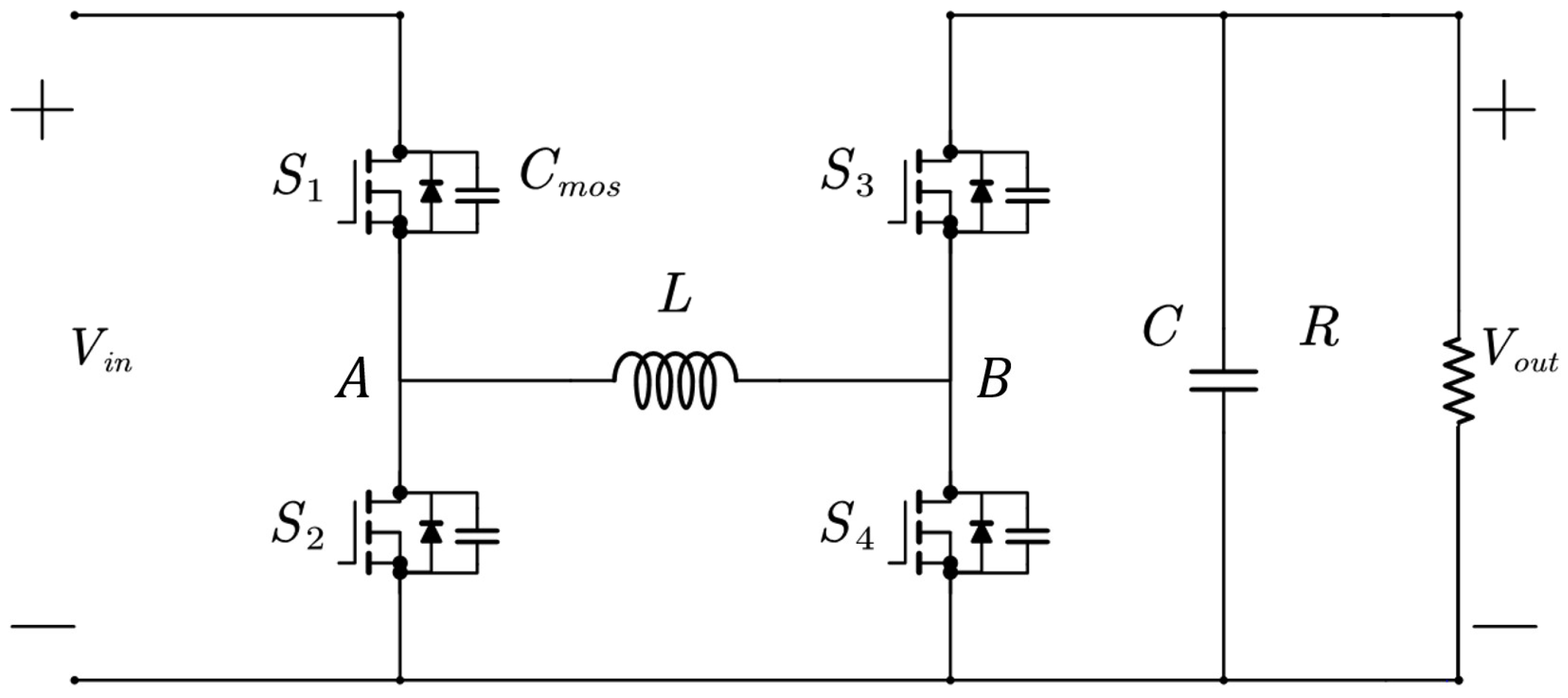
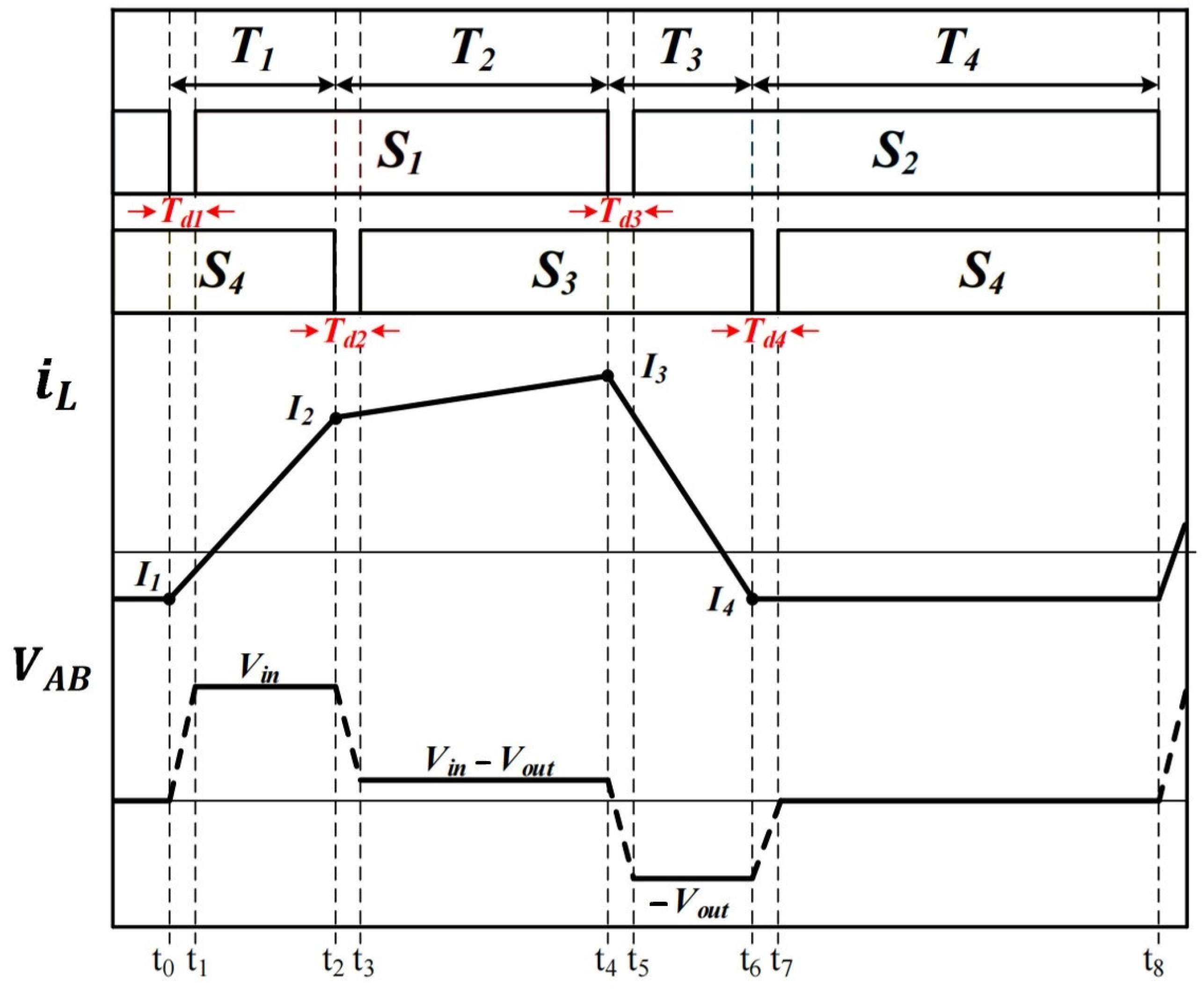
2. FSBB Converter Working Mode Analysis

The four-switch Buck-Boost converter circuit topology is shown in Figure 1, where the two switches S 1 and S 2 of the front bridge arm are complementary to each other, and the two switches S 3 and S 4 of the rear bridge arm are complementary to each other, so that the duty cycles of switches S 1 and S 3 are defined as D 1 and D 2 , and those of S 2 and S 4 are 1 D 2 and 1 D 2 , respectively, and the midpoints of the front and rear bridge arms are A and B, respectively, with the energy-storing inductors connected between them.
According to the different on-time sequences of S 1 , S 2 , S 3 , and S 4 , the voltage V A B at the two ends of the inductor exists in four cases: V i n , V i n V o u t , V o u t , and zero voltage, which correspond to the four phases shown in Figure 2, and the duration of each phase is defined as T 1 , T 2 , T 3 , and T 4 , respectively.
[ t 0 t 1 ]: within this phase, the ZVS of the switching S 1 can be realized by the dead time T d 1 .
[ t 1 t 2 ]: During the energization phase, S 1 and S 4 are on and S 2 and S 4 are off. At this time, V A is connected to input V i n through S 1 , V B is connected to the ground through S 4 , and the voltage V A B is V i n at both ends of inductor L . The current I L starts to increase linearly from negative to positive, and the duration is T 1 , whose value should be as follows:
Δ I L 1 = T 1 · V i n L .
[ t 2 t 3 ]: During this phase, the ZVS of switching S 3 can be realized by the dead time T d 2 .
[ t 3 t 4 ]: During the direct power transfer phase, S 1 and S 3 are on and S 2 and S 4 are off. At this time, V A is connected to the input V i n through S 1 , V B is connected to the output V o u t through S 3 , and the voltage V A B is V i n V o u t at the two ends of inductor L . The current I L continues to increase or decrease linearly for the duration of T 2 , and the slope is as follows:
Δ I L 2 = T 2 · | V i n V o u t | L .
[ t 4 t 5 ]: During this phase, the ZVS of switching S 2 can be realized by the dead time T d 3 .
[ t 5 t 6 ]: During the reset phase, S 2 and S 3 are on and S 1 and S 4 are off. At this time, V A is connected to the ground through S 2 , V B is connected to the output Vout through S 3 , the voltage V A B at both ends of inductor L is V o u t , the current I L decreases linearly, the duration is T 3 , and the slope is as follows:
Δ I L 3 = T 3 · V o u t L .
[ t 6 t 7 ]: During this phase, the ZVS of switching S 4 can be realized by the dead time T d 4 .
[ t 7 t 8 ]: During the continuity phase, S 2 and S 4 are on and S 1 and S 3 are off. At this time, V A is connected to the ground through S 2 , V B is connected to the ground through S 4 , the voltage V A B at both ends of inductor L is zero, and the current I L keeps flowing in the negative direction, unchanged (the slope is 0).
Δ I L 4 = 0
The magnitude of the voltage gain and the duration of the four operating modes of the FSBB converter are controlled by two duty cycles, D 1 , D 2 , and one phase shift duration, D 3 . According to the volt-second characteristic of the inductor, the voltage integral of the inductor in one cycle should be zero in the ideal case of renewal, resulting in the following:
V i n T 1 + ( V i n V o u t ) T 2 = V o u t T 3 .
The collation yields the following:
G = T 1 + T 2 T 3 + T 2
where G is the voltage gain ratio, the ratio of the output voltage to the input voltage. In previous studies, the dead time is often partially ignored and merged with the duration of each control mode, but for the FSBB design that plans to realize ZVS, especially in low-frequency and high-load systems working in the critical range, the effect of the dead time is not to be ignored, and so the operating time is related to the values of D 1 , D 2 , D 3 . Taking this relationship into account, the results are as follows:
T 1 = D 3                                               T 2 = G D 2 D 3                     T 3 = D 2 + D 3 G D 2 T 4 = 1 D 2 D 3             .
From the above equation:
G = D 1 D 2 .
When the fixed input voltage and the desired output voltage are known, D 1 can be replaced by the product of D 2 and the voltage gain G . Thus, the values of D 2 , D 3 can be analyzed in order to optimize the efficiency at a fixed voltage gain magnitude.

3. FSBB Converter Based on WMA Algorithm

3.1. Optimization of FSBB Converter Objective Function Based on WMA Algorithm

In order to explore the possibility of optimizing the efficiency of circuit operation, the concept of direct power is introduced, which is defined as the power that is transmitted directly from the power source to the load without conversion by the energy storage element. Both Buck and Boost converters have direct power, while traditional Buck-Boost converters need to charge the inductor first, and then the inductor provides power to the load. There is no direct power from the power supply to the load, so there is no direct power, which is the advantage of the FSBB converter. Analyzing from the perspective of the RMS value of the inductor current, the T 1 duration mainly affects the peak value of the inductor current, and an increase in the T 1 duration means an increase in the T 3 duration at the same time, which also increases the RMS value of the inductor current as a whole. So in order to reduce the RMS value of the inductor current, it is necessary to maximize the proportion of the increase in direct power to reduce the weight of T 1 and T 3 over the entire cycle. The objective function is set as follows:
E = ( 1 G ) D 2 + 2 D 3 .
Through the above equation, it can be seen that when in Buck mode, when G < 1 , the smaller D 2 , D 3 are, the smaller the objective function is, and the smaller the ratio of T 1 , T 3 is. When in Boost mode, when G > 1 , the larger D 2 is, the smaller D 3 and the objective function are, and the smaller the value of T 1 , the smaller T 3 is. Although the values of D 2 and D 3 cannot be varied indefinitely due to other constraints, the introduction of the direct power concept provides a clear direction for the optimization of the efficiency and, at the same time, avoids the integral part of the calculation of the rms value, which simplifies the operation, reduces the overall number of iterations, and increases the computational efficiency.

3.2. Constraints for FSBB Converter Based on WMA Algorithm

3.2.1. Boundary Condition Limitations

The chaotic switching of modes will affect the characteristics of the converter, making the optimization calculation complicated, and will lead to an increase in losses due to the repeated turning on and turning off of the switches. Therefore, in order to ensure that the four operating states T 1 , T 2 , T 3 , T 4 are carried out sequentially, there are no repeated changes in the operating modes due to D 2 , D 3 at certain values, and it is necessary to ensure that the four operating hours are greater than 0. From the above equation:
E = ( 1 G ) D 2 + 2 D 3 .

3.2.2. ZVS Implementation Limitations

The ZVS of the four switches can be realized by inserting the dead time between the two phases of the four operating modes of the FSBB. The minimum dead time to meet the requirements of the ZVS is different for different operating conditions, and if the dead time is also taken as the target of the dynamic control of the converter, the converter needs to be delayed within the cycle of the high frequency, and this will increase the difficulty of control. Therefore, in this paper, after analyzing the limitations of ZVS, we have chosen to empirically set enough switching time to ensure that the switching parasitic capacitance is fully discharged to realize ZVS under most of the working conditions.
During the dead time at the end of each phase, inductor L   and the parasitic capacitance C m o s of the switching form a resonant loop, and to reduce the voltage to zero during the dead time, the current in each time period needs to satisfy the following:
I L 1 V i n 2 C m o s L I L 2 V o u t 2 C m o s L I L 3 V i n 2 C m o s L I L 4 V o u t 2 C m o s L .
It can be seen that the side with the higher voltage requires a longer dead time, and while the current of the inductor in the T4 time period is ideally a constant value—let this value be I m = I L 1 = I L 4 —then, from the above equation, the requirement for this value is as follows:
I m m a x ( V i n , V o u t ) 2 C m o s L .
The actual runtime I m value needs to satisfy the above conditions for ZVS to be realized.

3.2.3. Ampere-Second Characteristic Limitations

According to the ampere-second characteristics of the capacitor, T 3 at low load current Buck, T 1 at Boost, and T 2 at full time must satisfy a certain duration to keep the load voltage stable, or else the I m will be too large, resulting in the inability to realize ZVS.
During stable operation of the converter, the capacitor current satisfies the below equation:
Δ i C ( t ) = T k T k + 1   I c ( t ) d t = 0 .
The amount of variation in the capacitor current across the four operating states during each switching cycle is given by the following equation:
Δ i c ( t ) = T k T k + T 1                     I C m d t T k + T 1 T k + T 1 + T 2               ( I C 3 I C 2 ) t T 2 + I C 2 ( I C 3 I C 2 ) T 1 T 2 d t T k + T 1 + T 2 T k + T 1 + T 2 + T 3   ( I C m I C 3 ) t T 3 + I C 3 ( I C m I C 3 ) T 1 + T 2 T 3 d t T k + T 1 + T 2 + T 3 T k + 1   I C m d t
I C m = I m + I 0 .
From the above equation, the relationship between I m and D 2 , D 3 can be derived as shown in the following equation, where T s is the duration of a complete cycle:
I m = T s D 2 I 0 + T S ( G D 2 D 3 ) 2 V i n V o u t T S G 2 D 2 2 V i n 2 2 L D 2 V o u t .
Combining the above formulas, the relational equation for controlling the size of I m based on T 1 , T 2 , T 3 can be obtained, and then combined with the constraints of I m , which in turn can lead to the range of values of D 1 , D 2 , D 3 under the condition of satisfying ZVS, so as to obtain the values of D 2 , D 3 under the optimal efficiency based on the values of the objective function.

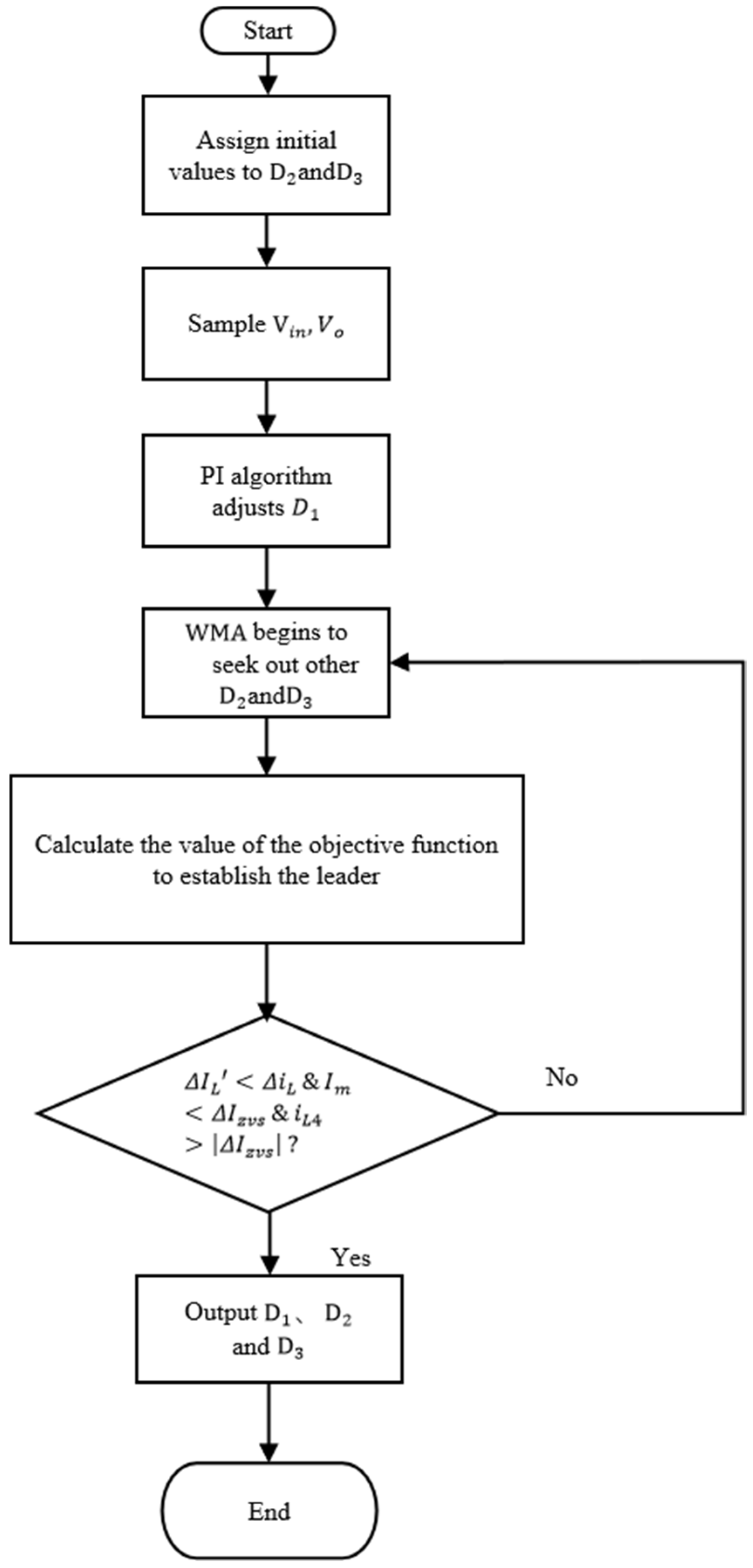
3.3. WMA Optimization Algorithm

3.3.1. Initialization

The population of migrating whales, the values of D 2 and D 3 , is randomly produced between the lower limit L and the upper limit U . The problem search space is given through Equation (17). This initial production population plays the role of a group of migrating whales, as shown in Equation (17):
W i = L + r a n d 1 , D U L , i = 1,2 , , N p o p ,
where the function ( 1 ,   D ) generates a vector of random numbers from the interval [ 0 ,   1 ] of dimension D and the operation n denotes the Hadamard product of two vectors, where each element of the resultant vector is obtained by multiplying the corresponding elements of the two original vectors.

3.3.2. Adaptation Evaluation

The fitness value is computed for each candidate solution, synthesizing the objective function with the following constraint penalty term:
F i t n e s s = E + λ P e n a l t y Z V S + μ P e n a l t y B o u n d a r y
where E is the value of the objective function of Equation (9); P e n a l t y Z V S penalizes solutions that violate the ZVS constraints; and P e n a l t y B o u n d a r y is the value of the fixed-height penalty when the boundary conditions are violated. In the fitness function, the objective function E dominates the efficiency optimization, while the penalty term enforces the satisfaction of ZVS and boundary conditions. The algorithm regulates the prioritization of both through weights λ and µ .

3.3.3. Current Location of Migrating Whales in the Ocean

In the proposed WMA algorithm, there is the parameter N L , which represents the number of more experienced leaders and consists of members with better and superior positions and objective function values. In this paper, we set   W M e a n to the average of the current N L leader positions.
W M e a n = 1 N L j = 1 N L   W j

3.3.4. Less Experienced Whales Move Toward Nearest Neighbors

It is assumed that all stock members (whales) are ranked in descending order of fitness value (or objective function value) and/or their position (or equivalent whale experience value):
W 1 , , W i 1 , W i , W i + 1 , , W N p o p
where W 1 is the best member (denoted as W B e s t in the following) and W N p o p is the worst member.

3.3.5. Less Experienced Whales Are Guided by More Experienced Whales

The current position of the entire migratory group in the ocean is assumed to be equal to the average of the current positions of all the more experienced whales,   W M e a n . If the distance between points   W M e a n and W B e s t begins to decrease, the entire migratory group is approaching W B e s t .
W i n e w = W M e a n + r a n d ( 1 , D ) ( W i 1 W i ) + r a n d ( 1 , D ) ( W B e s t W M e a n ) , i = N L + 1 , , N p o p

3.3.6. Discovery and Search of New Territory by Experienced Whales or Leaders

In a group of migrating whales, the most experienced individual, called the leader, is responsible for recognizing and choosing the best route to reach the destination. According to the following kinematic equation, the i t h whale will search for this suitable path to reach its destination:
W i n e w = W i + r 1 L + r 1 r 2 U L , i = 1 , , N L , .

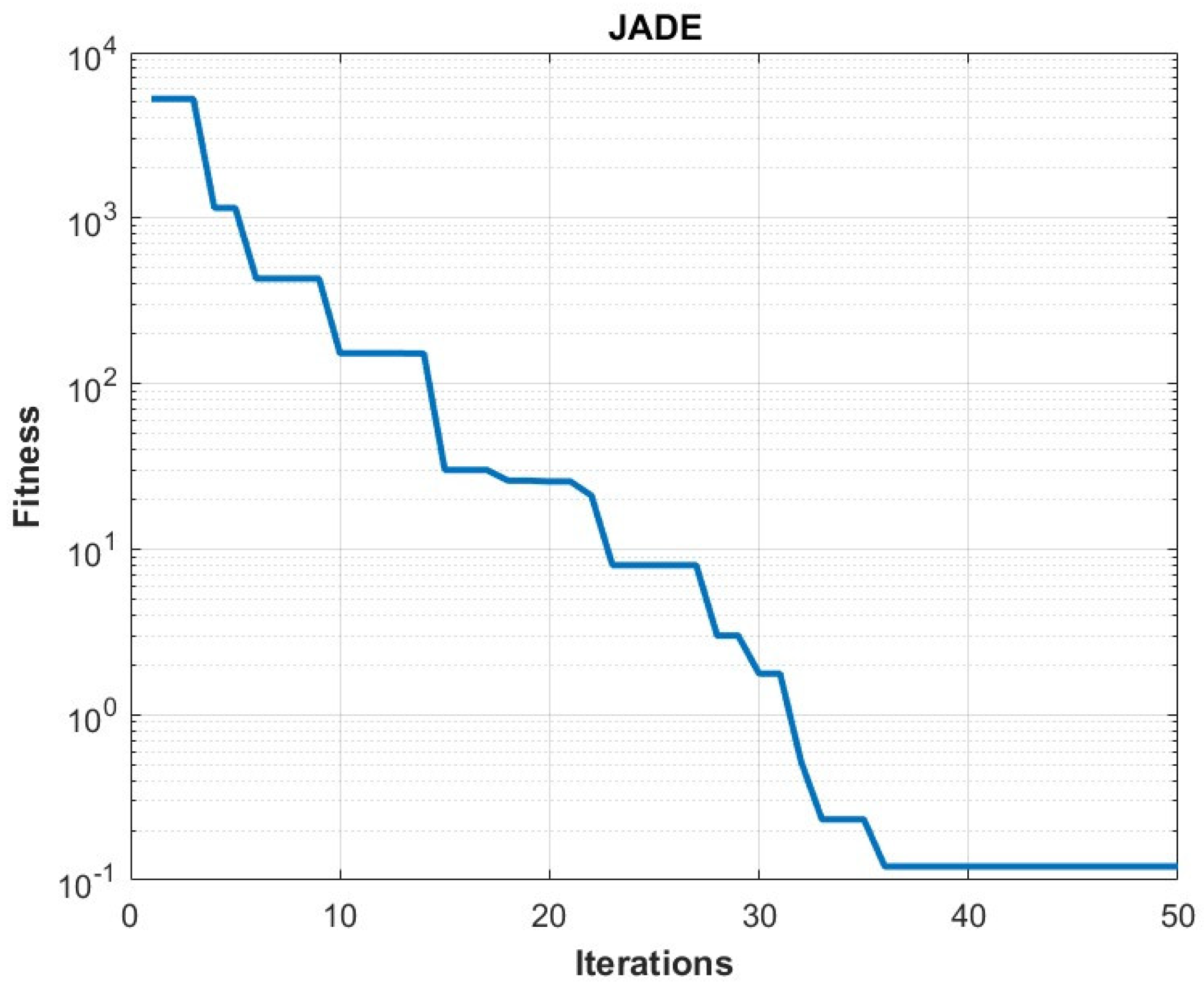
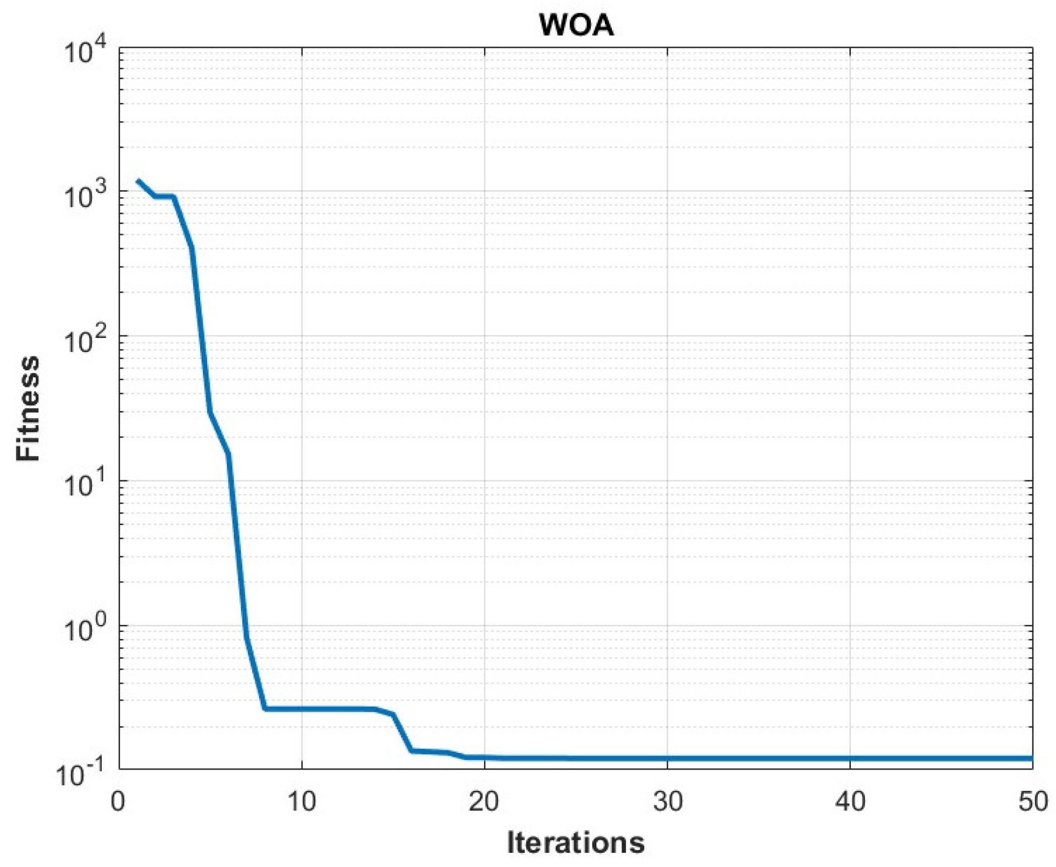
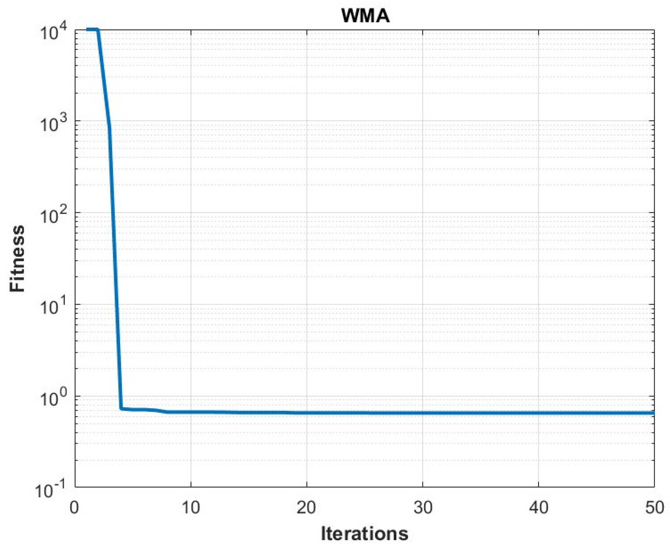
3.4. Comparison of Optimization Algorithms

In order to analyze the performance advantages of different algorithms applied to FSBB converter optimization, the number of iterations required to reach the optimal solution is used as a criterion for evaluating the performance of the algorithms, using the above FSBB optimization model as an application. Optimization tests were carried out in matlab using three different algorithms with the data shown in Table 1, and the number of iterations required to reach the optimum was recorded, thus creating an image of the optimum fitness value and the number of iterations in the logarithmic coordinate system [18,19].
The simulation results are shown in Figure 3, Figure 4 and Figure 5. It can be seen that the optimization using the WMA algorithm converges faster compared to the rest of the control algorithms, and at the same time, it is less likely to fall into local convergence and has a strong global search capability.
The optimization was tested using three different algorithms under the same conditions and the number of iterations required to reach the optimum was recorded.
Table 2 presents the results of the multiple iterations of the test, where WMA exhibits a superior convergence rate, reaching the optimal solution in about 10.6 iterations compared to JADE, which requires 38.5 iterations and even shows non-convergence, and WOA, which requires 24.1 iterations. This improvement can be attributed to the chaotic sequences in CPSO, which help to explore the search space more efficiently in the initial phase of the optimization process.
WMA converges faster compared to other algorithms, which reduces the number of iterations required to reach the optimal solution, thus increasing the computational efficiency during system runtime.

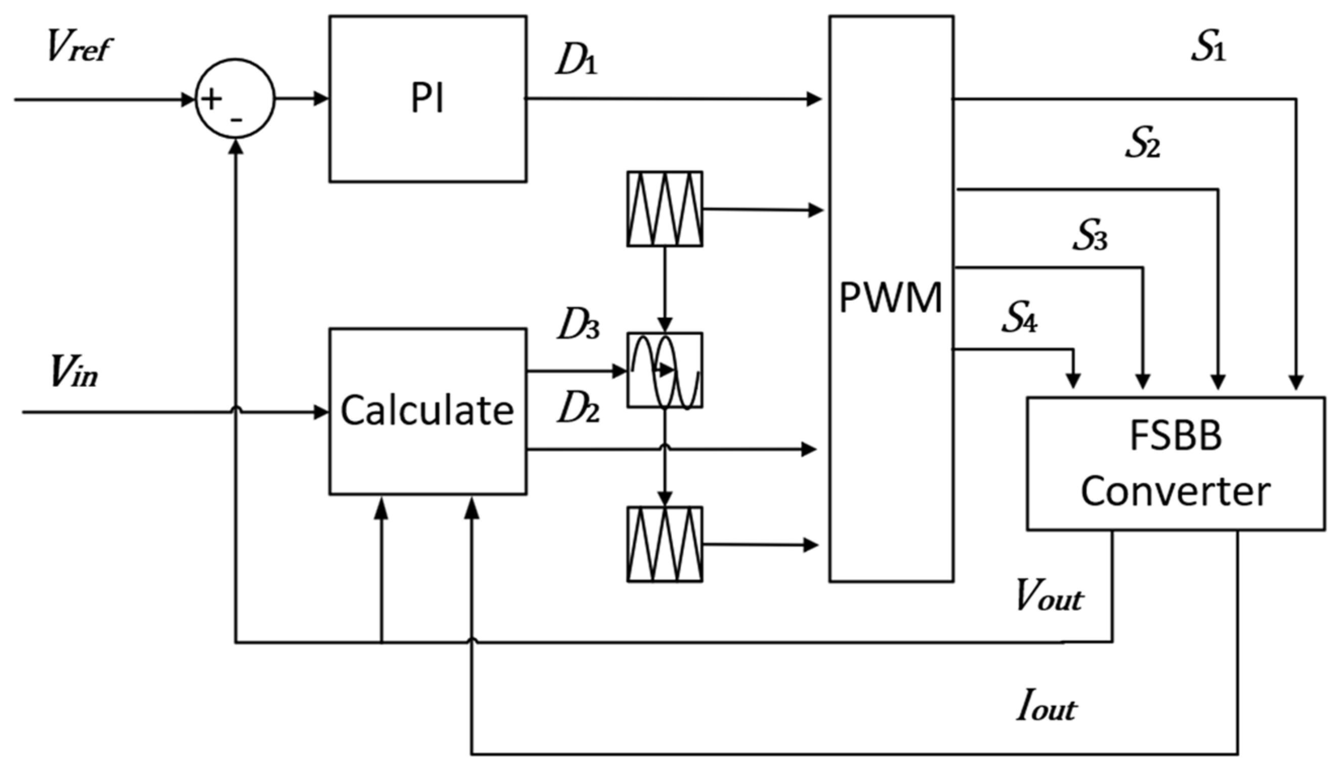
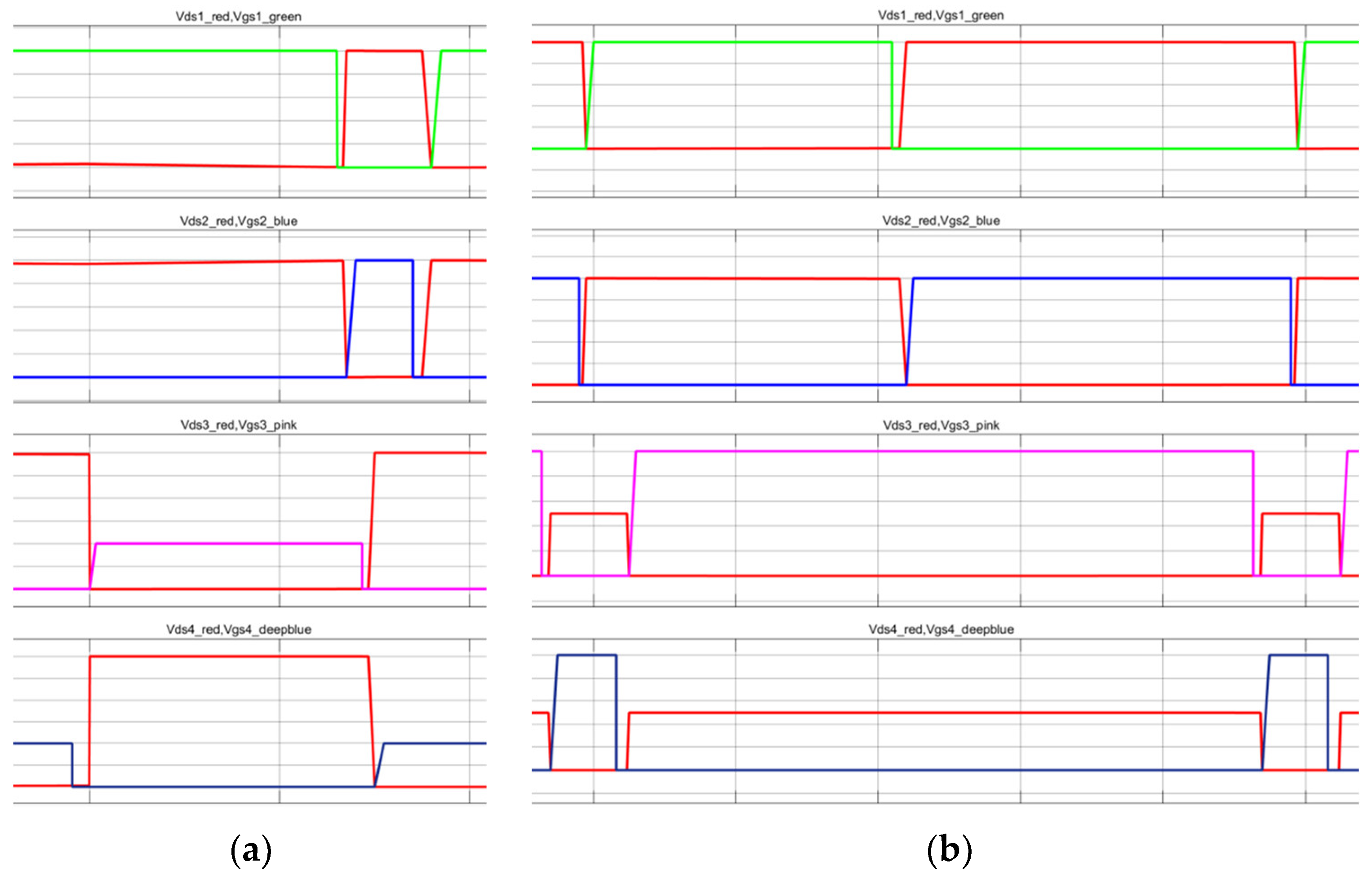
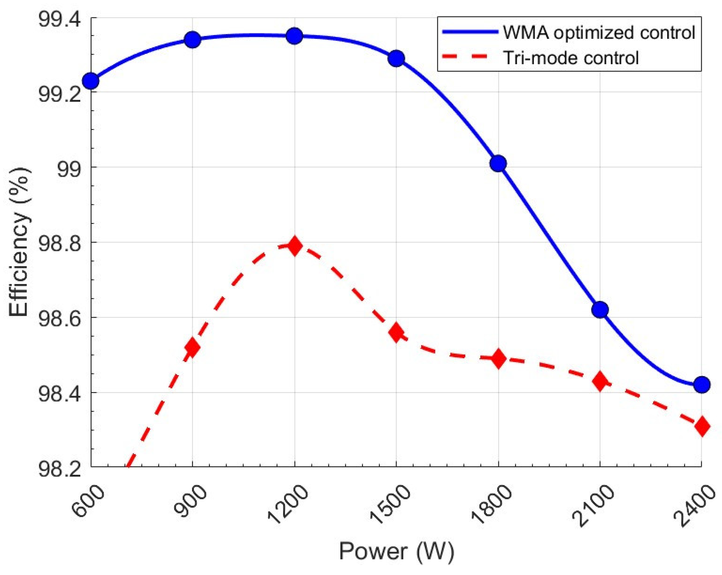
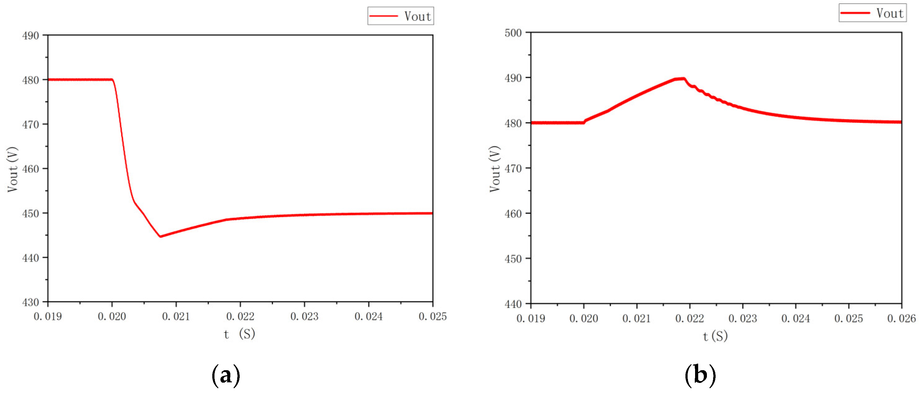
4. Control Strategy and Simulation Verification

The optimized control process based on the WMA algorithm proposed in this paper is shown in Figure 6. First, preset values for D 2 and D 3 are initialized. When the converter starts operating, parameters such as the output voltage are collected and fed into the PI controller to adjust D 1 . Simultaneously, the WMA optimization algorithm begins functioning. Based on the input voltage and other collected operating conditions, the algorithm calculates optimized values for D 2   and D 3 under the current voltage and load. After passing logical judgment to satisfy the constraints mentioned earlier, these values are sent to the delay module and PWM module to control the four switches of the converter. This achieves zero-voltage soft-switching control and reduces the effective value of the inductor current, thereby minimizing losses.
Figure 7 illustrates the control block diagram of the proposed strategy. The control variables involved are the duty cycles D 1 , D 2 , and the phase-shift ratio D 3 . Here, D 1 is regulated by the output voltage stabilization PI loop, while D 2 and D 3 are derived from the WMA optimization algorithm. The PI control loop operates as a fast-priority circuit, whereas the dynamic ZVS optimization algorithm functions as a slow-priority loop. The dynamic optimization algorithm for ZVS only activates when the PI algorithm stabilizes the output voltage.
Using the parameters in Table 3, the corresponding system simulation model was developed in MATLAB/Simulink (version 23.2.0.2365128, R2023b) to simulate and validate the proposed optimized control strategy.
Figure 8 shows simulation plots of the drain-source voltage V d s versus the gate-source level control signal V g s for the four switches at different variable ratios of G = 3 and G = 0.5 , respectively. The red waveform represents the drain-source voltage, and the other colors represent the gate-source level control signals.
It can be seen that the V d s and V g s plots of all four mos-tubes are uncrossed, demonstrating that the control strategy proposed in this paper achieves the critical ZVS at different voltage gain ratios G and load ratings, which reduces the switching losses and improves the efficiency.
The following figure demonstrates the efficiency of the FSBB circuit optimally controlled using the WMA algorithm in this study compared to the efficiency of an FSBB circuit with conventional three-mode control under different load powers.
Figure 9 shows that the maximum transmission efficiency of the optimized circuit reaches 99.34% under lighter loads, and the corresponding peak transmission efficiency under the traditional three-mode control is 98.79%. The transmission efficiency under high loads is also significantly improved—compared with the traditional control method, the efficiency of the FSBB circuit optimized and controlled by the WMA algorithm proposed in this paper is maximally improved by 1.19%, and the output efficiency remains high under a larger variable ratio.
Figure 10a shows an image of each parameter of the converter when the target output voltage is adjusted from 480 v to 450 v at the rated input voltage, and it can be seen that the converter completes the adjustment process in about 1.9 ms, with a voltage drop of 5.2 v, and Figure 10b shows an image of each parameter of the converter when the output voltage is rated at 480 v, and when the input voltage is adjusted from 240 v to 270 v, the output voltage increases by 9.67 v. The adjustment time is 4.5 ms, and the operating conditions in Figure 10 show that the optimized control method proposed in this paper has a fast dynamic adjustment speed and good stability.

5. Conclusions

In this paper, an FSBB converter control method using the WMA algorithm for efficiency optimization is proposed, which effectively solves the problem of it being difficult to improve the transmission efficiency of FSBB converters by dynamic optimization of multiple control objects through the optimization control of duty cycle and phase shift parameters.
By analyzing and summarizing the constraints and control variables of the FSBB converter during the working process, the theoretical foundation is laid for optimal control using the algorithm.
As shown when comparing the computing performance of different algorithms with the FSBB converter optimization model, the WMA algorithm requires fewer iterations to reach the optimal solution, which confirms the advantage of the WMA algorithm in dealing with the efficiency optimization of the FSBB converter.
Based on the above study, suitable constraints and objective functions have been set to optimize the duty cycle and shift ratio. By optimizing the duty cycle and shift ratio, the switching and inductive losses of the FSBB converter are reduced, the operating efficiency of the FSBB converter is improved, the FSBB converter achieves high efficiency over a wide voltage range, and the converter shows good stability. The converter achieves a maximum efficiency of 99.34%, an improvement of 1.19% over conventional three-mode control.

Author Contributions

Conceptualization, Z.H. and Y.X.; methodology, Z.H.; software, Z.H.; validation, Y.X. and J.B.; formal analysis, Z.H.; writing—original draft preparation, Z.H.; writing—review and editing, Y.X. All authors have read and agreed to the published version of the manuscript.

Funding

This research was funded by Jilin Provincial Department of Science and Technology, China, grant number 20230204093YY.

Data Availability Statement

The data used to support the findings of this study are available from the corresponding author upon request.

Conflicts of Interest

The authors declare no conflicts of interest.

References

  1. Active Inductor Current Balancing for Interleaving Multi-Phase Buck-Boost Converter | IEEE Conference Publication | IEEE Xplore. Available online: https://ieeexplore.ieee.org/document/4802708 (accessed on 13 May 2025).
  2. An Improved Single-Mode Control Strategy Based on Four-Switch Buck-Boost Converter | IEEE Conference Publication | IEEE Xplore. Available online: https://ieeexplore.ieee.org/document/9124612 (accessed on 13 May 2025).
  3. Four Switch Buck-Boost Converter for Photovoltaic DC-DC Power Applications | IEEE Conference Publication | IEEE Xplore. Available online: https://ieeexplore.ieee.org/document/5674983 (accessed on 16 April 2025).
  4. An Interleaving Double-Switch Buck-Boost Converter for PV Grid-Connected Inverter | IEEE Conference Publication | IEEE Xplore. Available online: https://ieeexplore.ieee.org/document/5618019 (accessed on 16 April 2025).
  5. Analysis of PWM Nonlinearity in Non-Inverting Buck-Boost Power Converters | IEEE Conference Publication | IEEE Xplore. Available online: https://ieeexplore.ieee.org/document/4592538 (accessed on 13 May 2025).
  6. The MPPT Application of the FSBB Converter with MHz ZVS Digital Control | IEEE Conference Publication | IEEE Xplore. Available online: https://ieeexplore.ieee.org/document/9959301 (accessed on 13 May 2025).
  7. Yu, Z.; Kapels, H.; Hoffmann, K.F. High Efficiency Bidirectional DC-DC Converter with Wide Input and Output Voltage Ranges for Battery Systems. In Proceedings of the PCIM Europe 2015; International Exhibition and Conference for Power Electronics, Intelligent Motion, Renewable Energy and Energy Management, Nuremberg, Germany, 19–20 May 2015; pp. 1–8. Available online: https://ieeexplore.ieee.org/document/7149059 (accessed on 23 May 2025).
  8. An Improved Quadrangle Control Method for Four-Switch Buck-Boost Converter with Reduced Loss and Decoupling Strategy | IEEE Journals & Magazine | IEEE Xplore. Available online: https://ieeexplore.ieee.org/document/9371427 (accessed on 16 April 2025).
  9. Four-Mode Control Strategy Based on Four-Switch Buck-Boost Converter. Available online: http://www.jops.cn/EN/10.13234/j.issn.2095-2805.2022.5.11 (accessed on 13 May 2025).
  10. Zhou, Z.; Li, H.; Wu, X. A Constant Frequency ZVS Control System for the Four-Switch Buck–Boost DC–DC Converter with Reduced Inductor Current. IEEE Trans. Power Electron. 2019, 34, 5996–6003. [Google Scholar] [CrossRef]
  11. Extreme High Efficiency Non-Inverting Buck-Boost Converter for Energy Storage Systems | VDE Conference Publication | IEEE Xplore. Available online: https://ieeexplore.ieee.org/document/7499359 (accessed on 16 April 2025).
  12. Xia, K.; Li, Z.; Qin, Y.; Yuan, Y.; Yuan, Q. Minimising Peak Current in Boundary Conduction Mode for the Four-Switch Buck–Boost DC/DC Converter with Soft Switching. IET Power Electron. 2019, 12, 944–954. [Google Scholar] [CrossRef]
  13. A Simplified Real-Time Digital Control Scheme for ZVS Four-Switch Buck–Boost with Low Inductor Current | IEEE Journals & Magazine | IEEE Xplore. Available online: https://ieeexplore.ieee.org/document/9519164 (accessed on 16 April 2025).
  14. The Research and Design of High-Efficiency Control Strategy for Four-Switch Buck-Boost Converter. Available online: https://epjournal.csee.org.cn/zgdjgcxb/en/article/doi/10.13334/j.0258-8013.pcsee.231719 (accessed on 16 April 2025).
  15. A Constant Frequency ZVS Modulation Scheme for Four-Switch Buck–Boost Converter with Wide Input and Output Voltage Ranges and Reduced Inductor Current | IEEE Journals & Magazine | IEEE Xplore. Available online: https://ieeexplore.ieee.org/document/9818858 (accessed on 16 April 2025).
  16. Liu, F.; Xu, J.; Chen, Z.; Yang, P.; Deng, K.; Chen, X. A Multi-Frequency PCCM ZVS Modulation Scheme for Optimizing Overall Efficiency of Four-Switch Buck–Boost Converter with Wide Input and Output Voltage Ranges. IEEE Trans. Ind. Electron. 2023, 70, 12431–12441. [Google Scholar] [CrossRef]
  17. Ghasemi, M.; Deriche, M.; Trojovský, P.; Mansor, Z.; Zare, M.; Trojovská, E.; Abualigah, L.; Ezugwu, A.E.; Mohammadi, S. kadkhoda An Efficient Bio-Inspired Algorithm Based on Humpback Whale Migration for Constrained Engineering Optimization. Results Eng. 2025, 25, 104215. [Google Scholar] [CrossRef]
  18. JADE: Adaptive Differential Evolution with Optional External Archive | IEEE Journals & Magazine | IEEE Xplore. Available online: https://ieeexplore.ieee.org/document/5208221 (accessed on 16 April 2025).
  19. Mirjalili, S.; Lewis, A. The Whale Optimization Algorithm. Adv. Eng. Softw. 2016, 95, 51–67. [Google Scholar] [CrossRef]
Figure 1. Topology of FSBB converter.
Energies 18 02807 g001
Figure 2. Main waveforms of FSBB converter.
Energies 18 02807 g002
Figure 3. Fitness curve for JADE.
Energies 18 02807 g003
Figure 4. Fitness curve for WOA.
Energies 18 02807 g004
Figure 5. Fitness curve for WMA.
Energies 18 02807 g005
Figure 6. FSBB converter flowchart.
Energies 18 02807 g006
Figure 7. FSBB converter closed-loop control system.
Energies 18 02807 g007
Figure 8. Waveforms of realized ZVS for different voltage gains (Red is V d s ,   o t h e r   c o l o r s   a r e   V g s ). (a) G = 3 .   ( b )   G = 0.5 .
Energies 18 02807 g008
Figure 9. Efficiency comparison curve.
Energies 18 02807 g009
Figure 10. Waveforms of FSBB converter during voltage variations. (a) Output voltage changed from 480 v to 450 v. (b) Input voltage changed from 240 v to 270 v.
Energies 18 02807 g010
Table 1. Simulation parameters.
Circuit ParametersValueCircuit ParametersValue
Input Voltage (V)240Inductance20
Output Voltage (V)720Output Capacitance100
Output Current ( I o u t / A )10Mos Capacitance100
Frequency100Dead time200
Table 2. Number of iterations to obtain optimal solution for three algorithms.
NumberJADEWOAWMANumberJADEWOAWMA
1492076463811
24020127-1327
3463878492216
4201969482110
5181661019344
Table 3. FSBB converter parameters.
Circuit ParametersValueCircuit ParametersValue
Input Voltage ( V i n / V)240–270Inductance ( L / μ H ) 50
Output Voltage ( V o u t / V)120–720Output Capacitance ( C o / μ F ) 100
Rated Power ( P o / W ) 600–2400Mos Capacitance ( C m o s / p F ) 100
Frequency ( f / k H z ) 100Dead Time ( t d e a d / n s ) 200
Disclaimer/Publisher’s Note: The statements, opinions and data contained in all publications are solely those of the individual author(s) and contributor(s) and not of MDPI and/or the editor(s). MDPI and/or the editor(s) disclaim responsibility for any injury to people or property resulting from any ideas, methods, instructions or products referred to in the content.

