Review

Exploring Hydrogen-Enriched Fuels and the Promise of HCNG in Industrial Dual-Fuel Engines

by
Grzegorz Szamrej
* and
Mirosław Karczewski
*
Faculty of Mechanical Engineering, Military University of Technology, 2 Gen, Sylwestra Kaliskiego St., 00-908 Warsaw, Poland
*
Authors to whom correspondence should be addressed.
Energies 2024, 17(7), 1525; https://doi.org/10.3390/en17071525
Submission received: 10 January 2024 / Revised: 7 March 2024 / Accepted: 13 March 2024 / Published: 22 March 2024
(This article belongs to the Special Issue Unconventional Hydrogen Applications and Systems)

Abstract

:
This paper presents a theoretical analysis of the selected properties of HCNG fuel calculations and a literature review of the other fuels that allow the storage of ecologically produced hydrogen. Hydrogen has the most significant CO2 reduction potential of all known fuels. However, its transmission in pure form is still problematic, and its use as a component of fuels modified by it has now become an issue of interest for researchers. Many types of hydrogen-enriched fuels have been invented. However, this article will describe the reasons why HCNG may be the hydrogen-enriched fuel of the future and why internal combustion (IC) piston engines working on two types of fuel could be the future method of using it. CO2 emissions are currently a serious problem in protecting the Earth’s natural climate. However, secondarily, power grid stabilization with a large share of electricity production from renewable energy sources must be stabilized with very flexible sources—as flexible as multi-fuel IC engines. Their use is becoming an essential element of the electricity power systems of Western countries, and there is a chance to use fuels with zero or close to zero CO2 emissions, like e-fuels and HCNG. Dual-fuel engines have become an effective way of using these types of fuels efficiently; therefore, in this article, the parameters of hydrogen-enriched fuel selected in terms of relevance to the use of IC engines are considered. Inaccuracies found in the literature analysis are discussed, and the essential properties of HCNG and its advantages over other hydrogen-rich fuels are summarized in terms of its use in dual-fuel (DF) IC engines.

1. Introduction

As environmental degradation continues, more and more attention is being paid to researching alternative sources of energy. One such source is HCNG fuel, a mixture of hydrogen and compressed natural gas (CNG), which can provide an alternative to traditional fossil fuels. This article will present some of the primary selected properties of HCNG fuel, which is produced by blending CNG fuel with hydrogen, and discuss how these properties affect the applicability of this fuel in compression ignition (CI) engines. The case will also be made that hydrogen-enriched fuel is the best option for CO2 emission reduction in engines currently in use.
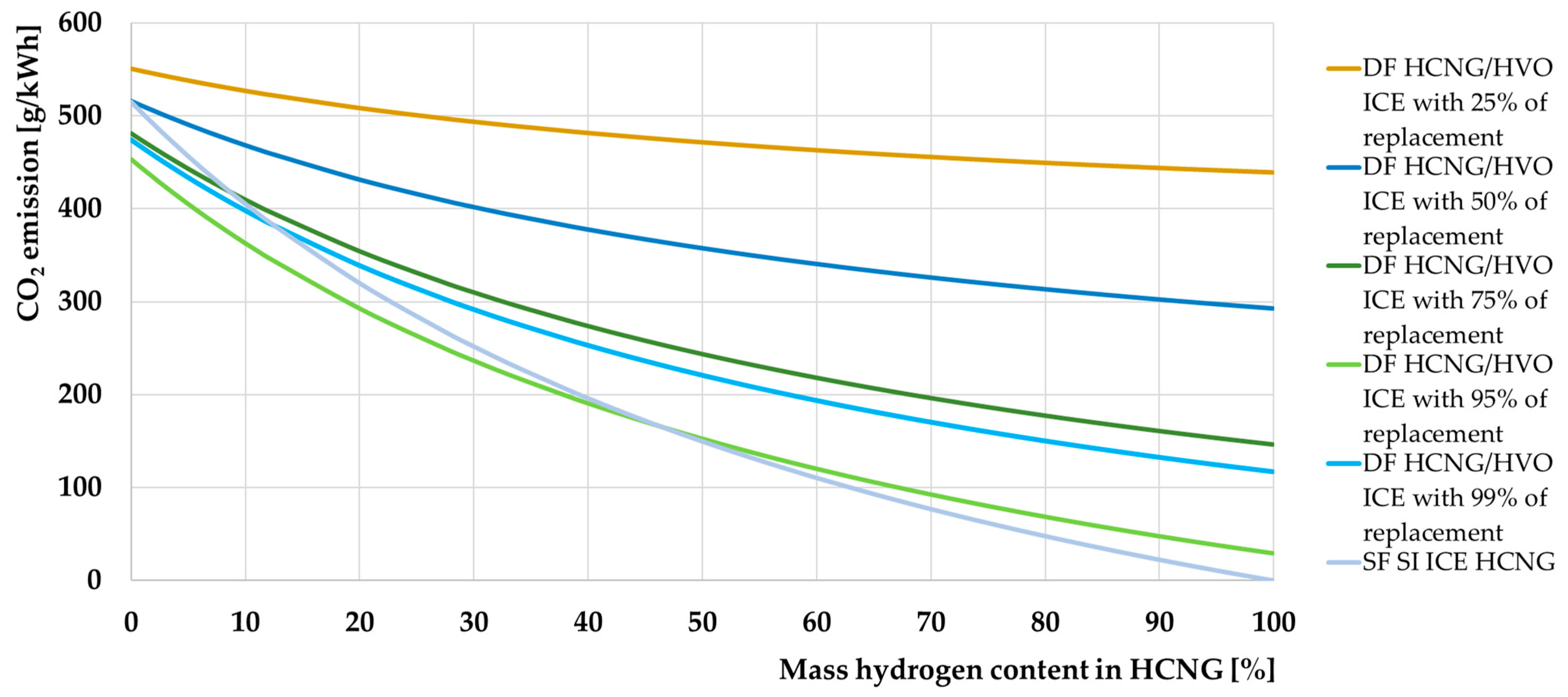
In the introduction, other methods of supplying hydrogen to internal combustion engines (ICEs) are compared with the possibilities of using HCNG fuel. The basic properties and formation of hydrogen are analyzed, and many issues related to its positive impact on the carbon footprints of industry and the transport and energy sectors are explained. The results of a comprehensive literature review is presented, based on which the critical properties of various HCNG fuel mixtures were determined. The primary objective of the article, resulting from the analysis and emphasizing the differences found in the literature, was to determine the possibilities offered by using HCNG in ICEs used in industry. These possibilities were shown in the form of simulated CO2 emission charts, efficiency changes, properties of HCNG, and conclusions. An analysis of the popular literature and problems arising from insufficient information concerning HCNG was also presented.

Explanation of the Introduction

Increasing environmental awareness is leading to the search for alternative sources of energy to replace traditional fossil fuels. Hydrogen represents one of the primary alternative sources of energy. Hydrogen’s role as an alternative to hydrocarbon fuels is currently limited due to the difficulty of its distribution and the costliness of its production [1]. Hydrogen is also an energy storage medium which can be competitive with other energy storage methods [2] due to its physical properties and its ability to be used as a fuel; in other words, it can be used to recover energy from mechanical energy (engines), thermal energy (engines and heating equipment), and electrical energy (fuel cells and power generators [3]). Due to the problems associated with using pure hydrogen, this fuel is used in various forms. This article outlines basic methods of storing hydrogen in the form of fuels and presents the advantages of individual hydrogen-rich fuels for use in ICEs, with a particular emphasis on the case of dual-fuel CI engines. With current trends in global energy development, such engines play crucial roles in stabilizing the electricity grid and providing flexible power generation options, which is why ICEs continue to attract the interest of researchers. The hydrogen usage problem in the context of the current needs of the energy market considered in this article is related to the possibility of hydrogen production by renewable energy sources and its ecological use in fuel cells or ICEs. For this reason, this article aims to select the most reasonable form of hydrogen-modified fuel used by high-efficiency DF CI engines, which have a very flexible response time to mechanical energy demand. Figure 1 shows the projected trend of change in daily electricity production associated with the development of sources of renewable energy, where we can see the short response time needed in the electrical grid when many solar systems are installed [4].
The graph on the left of Figure 1 is from 2010 and shows a situation that is already beginning to affect the US and EU electricity markets. The graph on the right shows the 2010 data, information about the power supply in 2030 and 2050, as approximated by [5], both with PV (photovoltaic) supply and without it, and the predicted PV production in 2050. Predictions from [5] consider future changes in energy demand, which were not considered in the graph on the left. Despite the reduction in energy consumption in Germany in the coming years, the ramp that occurs after intense insolation during the day is very sharp, both in the 2050 and 2010 × 10 solar power installed scenarios. The occurrence of such phenomena will be a demanding challenge for the electricity production systems. Fast activation of controllable energy generation components within the system will require using energy sources with a very short start-up period to full power. A large amount of installed RES dependent on solar power leads to huge daily fluctuations in electricity production and requires excellent flexibility on the part of electricity producers, who must be responsible for the amount of power available in the grid to shut down and restart electricity production on a daily basis [6]. Such significant variations often depend on the current insolation, which can also vary during the day, requiring an immediate response from energy suppliers [7]. Such short response times are achievable for few energy producers, and of those that can use hydrogen for this purpose, only combustion engines and fuel cells can be mentioned [3,8,9]. The latter is not only still not a widely available technology [10], but also has to use hydrogen in its pure form, which will be explained in this article as a serious drawback to their use. As far as ICEs are concerned, only reciprocating piston engines show sufficient flexibility to use hydrogen in any form. There currently needs to be more information available to determine the suitability of hydrogen-enriched fuels for power generation in turbine combustion engines. ICEs have a remarkable ability to serve as sources of electrical power [11]. Hydrogen-modified fuels can, therefore, be used primarily in reciprocating engines, among which CI DF engines show the highest efficiency in using the energy contained in the fuel, as the author has already demonstrated in previous publications [12,13,14,15]. In the 2050 scenario, the potential for hydrogen production can be observed when all energy demand is supplied by photovoltaic energy, and there will still be excess energy in the energy system. This creates the potential to store the excess energy produced, e.g., as chemical energy, in the form of hydrogen [7]. The number of energy storage facilities enabling the storage of electricity in chemical batteries has its limits, which will be able to be supplemented by hydrogen in the future. Such hydrogen, produced during periods of excessive electricity production by photovoltaic installations, will be used to fuel ICE, enabling the production of electrical energy during a sharp increase in demand while production by PV installations decreases.
Apart from proving the viability of using ICEs in the following years, this section emphasizes the novelty of this article and the justification for its publication. In addition to deciding which hydrogen-rich fuels will allow for the most effective reduction in carbon dioxide emissions by modern dual-fuel engines, this article develops HCNG fuel parameters with a precise range of achievable values that cannot be found in the available literature at the time of writing. The literature analysis conducted showed a lack of concrete answers to the following question posed by the authors:
“What are the values of the key physicochemical properties of natural gas and hydrogen mixtures, from the point of view of using those mixtures in DF ICE as the main fuel, depending on their hydrogen concentration?”
The following sections of this article provide an answer to the aforementioned question.

2. Materials and Methods

2.1. Methodology and Materials Selection

The materials used in this article are based on the literature analysis and mathematical calculations following widely known conventions, the principles of which were also based on the literature sources. Most of the sources were rejected during the research, and the sources considered worthy of citation were those with a high level of reputation and safety from the point of view of the certainty of the correctness of the data they contain. Additionally, when a popular science source was quoted, it had its justification. The method that allowed for calculating the value of a given physical or chemical parameter of the hydrogen–methane mixture was to select extreme values that were within the acceptable literature framework and to select data that allowed for the creation of a specific framework in which the given parameter of the HCNG fuel is defining. Information about the data source used in the calculations is always provided with the calculation results.

2.1.1. Explanation of the Selection of a Specific Fuel for Further Consideration
As a key part of this study, a literature analysis of the subject was carried out, and calculations based on the collected data were prepared. The calculations were based on commonly available and well-known mathematical formulae and physical relationships. The graphs presented will describe the effect of increasing hydrogen content on selected HCNG properties relevant to using this fuel in ICEs. It is important to note that the properties of the two fuels found in various sources differ significantly, which leads to discrepancies in calculations of the properties of HCNG itself. This will be described and highlighted in the chart showing the two extreme values developed from the available data, and the values in between may be taken as possible for this fuel. Hydrogen is often currently only as “green” as the means of producing it. This is because its natural occurrence is rare and it is not extracted in as large quantities as hydrocarbon fuels. Its occurrence in its pure form in nature has not been used on a mass scale so far, but this type of source has existed for a long time [16], and this type of hydrogen is called white hydrogen [17]. Its deposits often occur together with deposits of natural gas or crude oil, which is best proven by the recent discoveries of its sources in France [18,19,20]. It is worth noting, however, that even white hydrogen will have an unavoidable carbon footprint related to the environmental costs of its extraction, purification, or distribution, and this will depend directly on the energy sources used to power these processes [21]. It should be mentioned that there are still no official guidelines regarding the methodology for calculating well-to-wheel (WTW) emissions from this type of mine source [22,23]. It is important information, too, that hydrogen does not have a defined global warming potential (GWP) value in a normative manner in law [24]. This means that it is not yet entirely possible to determine the impact of the mass extraction of white hydrogen on the environment [25,26].
Hydrogen production in Europe is mainly achieved through steam reforming, water electrolysis, and coal gasification [27]. Further on in the article, there will be various ways of producing hydrogen illustrated—not only those prevalent in the European Union. Two of the world’s most commonly used methods are summarized in Table 1 below, showing the impact of each method on carbon dioxide emissions, depending on the method used and the hydrogen concentration in the HCNG produced.
Steam reforming is the most common method of producing hydrogen in Europe. It involves heating natural gas (NG), oil, or biomass in the presence of steam in a reactor, which releases hydrogen and carbon dioxide. This method is used in 96% of hydrogen production [27]. “Producing a unit of hydrogen from water requires four times more energy than from hydrocarbons”—this sentence helps us understand why 96% of world hydrogen production is based on this method. However, it is good to know that production from biomass can be much more climate-neutral and have similar advantages as hydrogen production from hydrocarbons [37]. Hydrogen in this method can be produced continuously and relatively cheaply in large quantities, but it also requires fossil fuels, which increases greenhouse gas emissions [38].
Water electrolysis is the second most common method of hydrogen production in Europe. The process involves passing an electric current through water, which causes the water molecules to break into hydrogen and oxygen. Electrolysis can be carried out using renewable energy sources to produce hydrogen in an environmentally friendly way, but the process is expensive and requires a large amount of electricity [39].
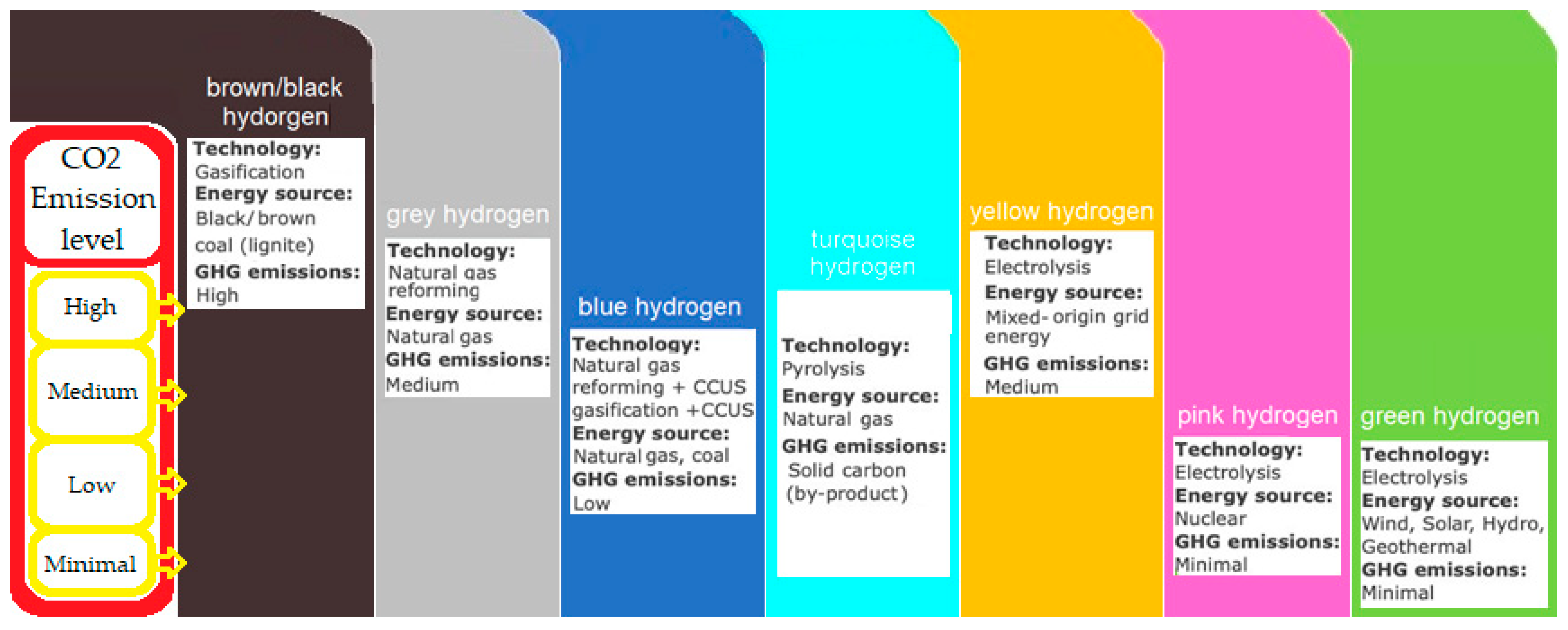
The third method popular in the EU is coal gasification, which converts coal into a synthesis gas that contains hydrogen and oxygen. The synthesis gas can then be converted into pure hydrogen [40]. This method is economically competitive because coal is relatively cheap, but greenhouse gas emissions are high, making it controversial and criticized because of its environmental impact. However, hydrogen produced from coal is a common fuel source among hydrogen-modified fuels [41], and this production method is one of the most efficient [42]. Figure 2 shows hydrogen production methods broken down by source, production method, and the level of greenhouse gas emissions associated with each method [43].
Entrepreneurs investing in hydrogen technologies must pay attention to hydrogen production and distribution costs, which are essential for business decisions. Many sources in [29,30,31,32,33,34,35,36] provide information not only about current prices and production costs but also about what the costs of hydrogen production were and will probably be in the future. The problem with providing production costs is that they may be subject to strong fluctuations resulting from the connection of costs with many factors. Additionally, the value of the currencies in which these costs are expressed also changes over time. For this reason, this article only hints at information about it without delving into this topic. In the case of costs, however, the same problem occurs as in other issues determining the various physical parameters of the fuels in question because, depending on the source, these costs may differ significantly from each other. Most sources provide them in a vast range of prices, which can be further analyzed in, for example, this position [32].
Additionally, these values depend on the place and exact date the material was developed, so it is not easy to compare them, unlike physicochemical properties. Therefore, to avoid speculating and maintain this article’s scientific character, the cost values are only mentioned indicatively. For an excellent example of the large dispersion in the value of costs it is worth reading this position paper [44]. A more critical parameter related to hydrogen production, which can be quite clearly defined, is the level of carbon dioxide emissions, i.e., the impact of hydrogen production on the environment, symbolically marked with colors assigned to a given method of obtaining hydrogen. A symbolic representation of the “rainbow” that illustrates various methods of producing hydrogen is shown in Figure 2 below.
Figure 2. Hydrogen production methods with hydrogen “colors” and typed production technology used energy sources and GHG emission levels—own drawing based on [43,45,46,47,48].
Energies 17 01525 g002
Hydrogen production is closely linked to the availability of technology and raw materials on site. There are more production types and categories than are shown on the graph and described in this article, but other research articles can deeply explore that topic [49,50,51]. Therefore, it may not be possible to consider producing and consuming hydrogen at a single site so that it has a proxy role similar to water in a pumped storage power station. Hence, the possibility of using it once transported to its final destination is significant. Hence, the issue of the form in which hydrogen is distributed after production arises and can be divided into several separate fuels:
  • hydrogen in pure form—compressed or liquefied;
  • methanol, HVO, and e-fuels;
  • hydrogen bound to nitrogen in the form of ammonia;
  • hydrogen is mixed with NG/methane to a compressed form of fuel named HCNG, H2CNG, or “hythane”.
Using hydrogen in its pure form is technically challenging, costly, complex, and energy-intensive. However, it can be distributed in a form bound with other elements, such as nitrogen in the form of ammonia [52], or in a mixture with other combustible gases, such as CNG in the form of so-called HCNG—a mixture of hydrogen and CNG. Its distribution in this form offers several advantages, the most important of which is using the existing CNG distribution infrastructure to distribute NG together with hydrogen [53]. The most significant advantages with which hydrogen, as a fuel, can be characterized are its high calorific value and the fact that no carbon dioxide is emitted when burning hydrogen. When used as a fuel, it can replace traditional fossil fuels [3].
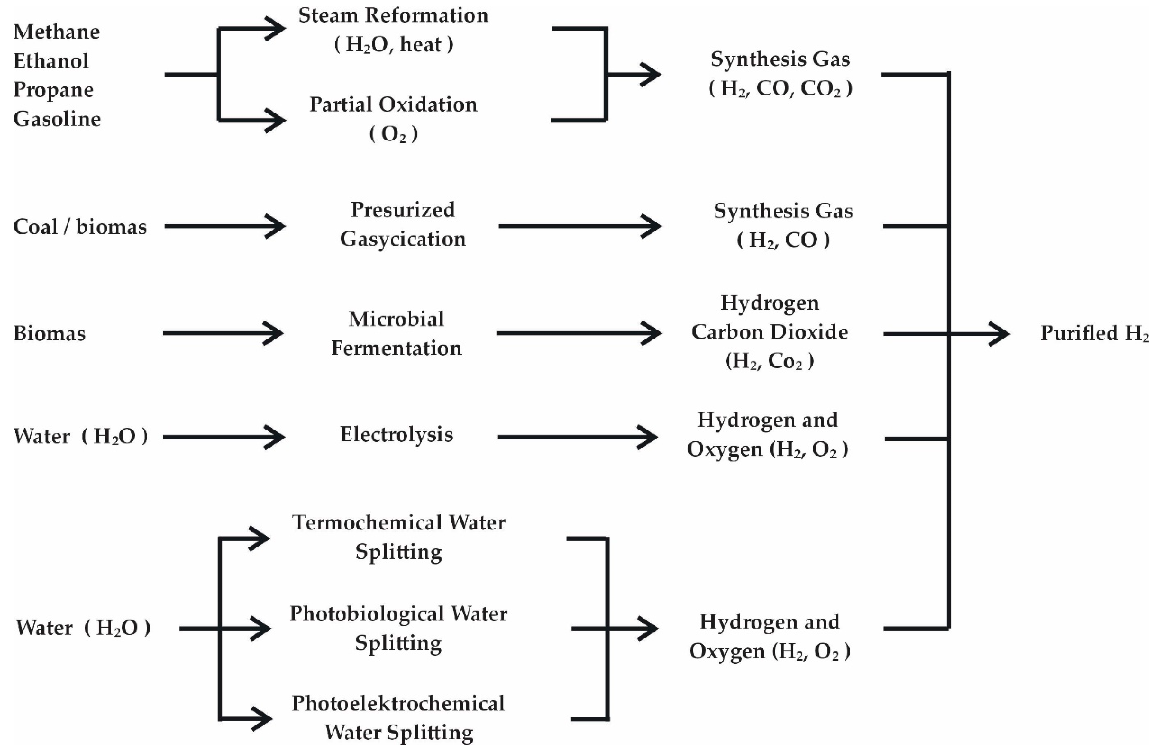
The following graphic (Figure 3) illustrates the production methods for hydrogen, collected together with information on the gases produced with hydrogen and the raw material from which these gases are produced.
There are more methods of producing hydrogen than in this article [55], but a closer look at the subject is necessary to understand the problem of creating HCNG fuel more fully. Many of the methods not mentioned here are often used in industrial processes. They are not associated with the mass production of hydrogen to allow its further distribution on a mass scale. Some are also completely unprofitable but are technically feasible and are often used because of other technological processes associated with them, e.g., in industrial plants [56]. However, it is worth knowing that the hydrogen created in this way can be a waste product and can be attempted to put into common usage, like hydrogen produced by more standard methods [57].
It is worth demonstrating how a few zero-emission methods have produced a small amount of hydrogen. The diagram below in Figure 4 from [58] shows the share of individual natural resources in the industrial production of this element.
The very intriguing article found in reference [58] also presents the relative costs of hydrogen production expected at that time for individual sources, where for water electrolysis, the relative cost was the highest among those mentioned, which explains such a low share of this method in the global hydrogen production.
The next section of this article will characterize the fuels that allow hydrogen to be used as a fuel produced by the abovementioned methods.

2.1.2. Hydrogen in Its Pure Form

Hydrogen is the simplest chemical element consisting of one proton and one electron. Under natural conditions on Earth, it is bound as a two-atom molecule [59].
One of the main problems with using hydrogen as a fuel is its low energy density compared to other fuels such as petrol or diesel. For this reason, a hydrogen tank needs to be much larger than the tank for other fuels to provide enough energy to cover the same distance. Hydrogen can also be stored as metal hydrides, but again, exceptional storage and transport conditions are required. These technologies are still in the research or testing phase and are unavailable for widespread use [60].
Another problem with using hydrogen as a fuel is its tendency to oxidize. Hydrogen gas is very reactive and easily forms explosive mixtures with oxygen or other oxidizers. A hydrogen flame is virtually invisible, increasing the risk of explosion hazards, which will be developed in the section that describes the properties of HCNG in this article.
There are, therefore, several reasons why hydrogen in its pure form is not used to power ICEs [3]:
  • The low energy density of hydrogen—hydrogen has a very low energy density, which means that much larger quantities of hydrogen are required to obtain the same amount of energy as from other fuels. In practice, required hydrogen storage tanks take up more space than tanks storing other hydrocarbon fuels, complicating the practical use of hydrogen for fueling ICEs [3].
  • Safety—hydrogen, in its pure form, is highly flammable and explosive. For this reason, it requires special safety measures during storage, transport, and use. This requires high costs and additional procedures, which increases costs and hinders its widespread use, but keep in mind that safety procedures apply to all hydrocarbon fuels [61].
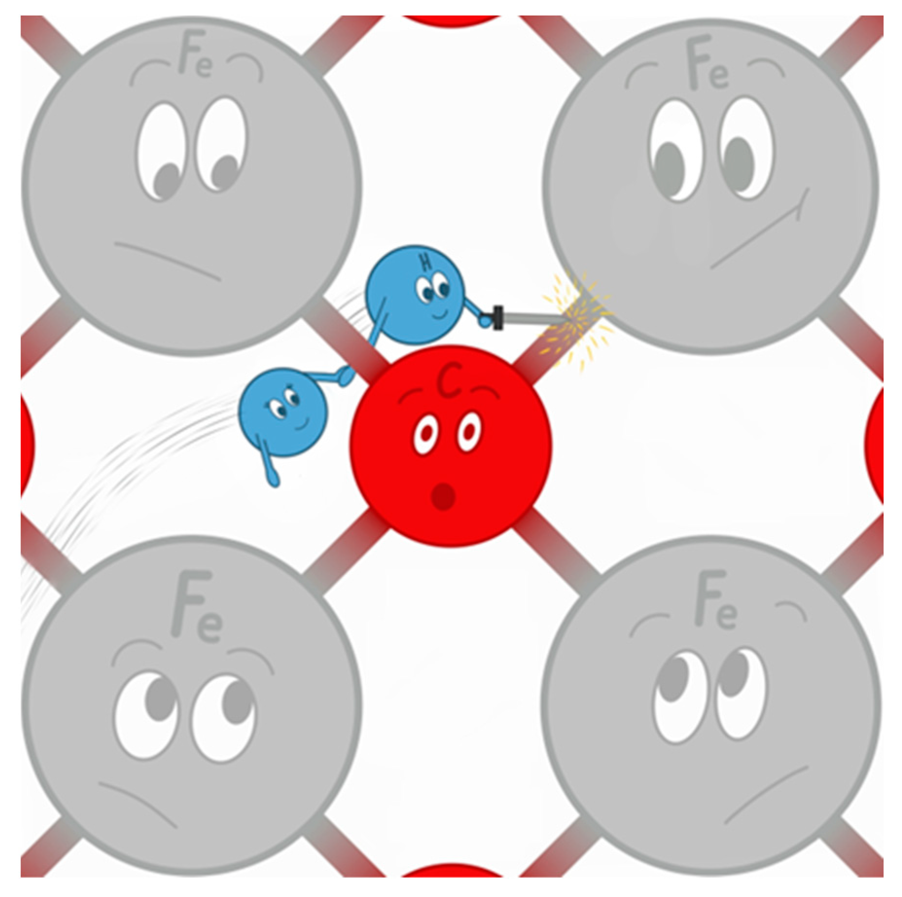
  • Reactivity—hydrogen is a highly reactive fuel. It readily reacts chemically with other elements, including oxygen, and causes the so-called hydrogen sickness in steel, i.e., the chemical corrosion related to the high permeability of this element, which penetrates steel structures and causes internal damage. This involves the need to use unique materials resistant to this phenomenon and the fact that hydrogen, as the lightest and smallest of all the elements, freely penetrates the structures of other substances. Hence, there is a permanent loss of hydrogen in the tank in which it is stored. This phenomenon cannot be avoided in the case of hydrogen stored in pure form [62]. Hydrogen reactivity is visualized in cartoon form in Figure 5.
  • Difficulty in distributing hydrogen—due to the lack of suitable infrastructure and the high reactivity of hydrogen, which causes hydrogen disease in steel in contact with it, as well as its permeability, as it can pass through structures that are not permeable to other fuels, such as steel pressure vessels, among others. For its mass distribution, tankers and pipelines will also be needed, and transport in its pure form cannot be based on the use of materials that are used to transport other liquefied or compressed hydrocarbon fuels [63].
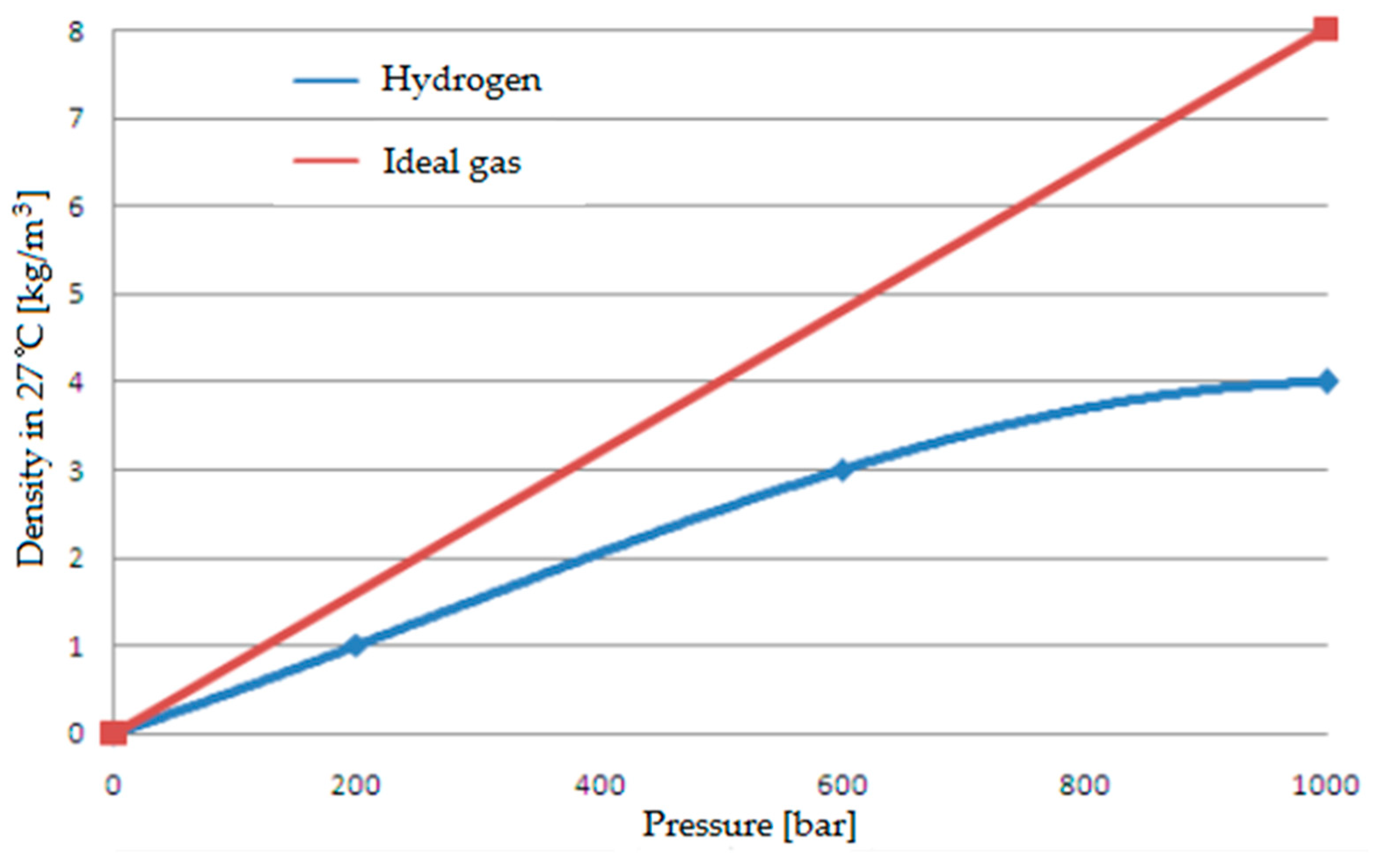
  • Storage difficulties—hydrogen gas requires special storage conditions. Tanks should withstand high pressure, and their material should resist hydrogen permeation and the hydrogen sickness it causes. Appropriate materials and technology must be used to ensure safety and optimum storage conditions. In its liquefied form, hydrogen requires very low storage temperatures and constant cooling due to the orthopnea transformations that occur in hydrogen, which gives off heat in this process. An additional factor in favor of the liquefaction method of stored hydrogen is the possibility of improving its purity with this method and the significantly higher potential for deifying the energy it contains. This is because the process of compressing hydrogen does not proceed as in the case of the compression of an ideal gas—as the pressure under which the compressed hydrogen is stored increases, the increase in its density decreases—thus increasing the amount of energy that must be put into further increasing the density of the compressed hydrogen. It is crucial to know that CNG is compressed under 200 atmospheres—compressed hydrogen is used under a pressure of about 300–700 atmospheres [64,65,66]. Compressing or liquefying hydrogen under such considerable pressures or low temperatures is expensive. The phenomena of the differences between hydrogen and ideal gas compression process can be seen in the graph in Figure 6 below, where hydrogen is compared with ideal gas [58].
  • Lack of infrastructure—the distribution problem, as mentioned earlier, also translates into the lack of a hydrogen distribution network, both on a local and global scale. All investments aimed at the mass transmission of hydrogen over longer distances are still only in the planning stage [67]. The local distribution network is deficient, and hydrogen can currently only be delivered to selected locations [68], often creating only temporary, local refueling stations [69].
  • Difficulty of production—hydrogen in its pure form is not found in natural sources, so it must be produced. Currently, the most common processes for producing hydrogen from hydrocarbon feedstocks involve greenhouse gas emissions and negative environmental impacts. All standard hydrogen production methods also involve the production of other substances (Figure 3). Pure hydrogen must, therefore, be separated from other products. Producing pure hydrogen is expensive but represents a milestone in organizing a zero-carbon economy. Product liquefaction is the most effective method of purifying the produced hydrogen from impurities, which involves cooling the produced gas below 20.4 K [49].
Due to these limitations, hydrogen in hydrogen-bearing forms, such as hydrogen bound to hydrocarbons, alcohols, or ammonia [70], or hydrogen in synthetic fuels, such as methanol or ammonia, are usually used more successfully. These fuels have a higher energy density and are easier to store, transport, and use in ICEs [71]. It is also possible to distribute hydrogen in liquid form (LH2), which is more costly to distribute but has the advantage of fitting more hydrogen mass into a smaller space [72]. This form of hydrogen storage is increasingly used in heavy transport or industrial usage [73,74,75,76,77], but it is still a rare option for commercial hydrogen use. There are ideas to store hydrogen in slush form [78], but it does not give a much higher energy density than others. The best option for hydrogen storage is still metal hydrides [79,80,81], which are still not developed enough for commercial use.
Hydrogen compression and lignification to LH2 fuel are related to the energy costs of bringing it to this state. Both hydrogen and NG must be compressed or compressed and chilled if they are to be stored in liquid form. Energy used for cooling and compressing is the cost of the gaseous fuel distribution. Hydrogen compression, as shown in Figure 6, is more inefficient than classical ideal gas and less effective than NG. Another disadvantage compared to NG is the hydrogen condensation temperature equal to 20 K (in normal pressure) and its triple point at 33 K level [82].
In comparison, NG has a condensation temperature at 111 K level [83] and a methane triple point equal to 90 K [84]. The differences are visible and indicate significantly lower requirements that must be achieved to liquefy methane compared to liquefying hydrogen. The theoretically determined minimum amount of energy needed to cool hydrogen, allowing its liquefaction, was 3.3 kWh, or 3.9 kWh, with the quantum conversion of this hydrogen, which is better described in the following parts of this article. The energy needed to compress hydrogen to a pressure of 350 atmospheres, at which liquefied hydrogen is typically stored, is 1.05 kWh/kg.
In comparison, its compression to 700 atmospheres requires consumption of at least 1.36 kWh/kg. This 1.05 kWh is more than 3% of the energy in H2 counted as a low heating value (LHV) for fuel compressed to 350 bars, more than 4% for 700 bars, and more than 14.7% for liquid hydrogen. Those values are calculated for theoretical minimal energy values. The actual liquefaction energy requirements are much higher and can be within the range of 10–13 kWh per kg of H2, which is 38.6% of its low heating value. With advanced liquefaction technologies such as magnetic hydrogen liquefaction, it was possible to reach the horizon of 7 kWh/kg, which is still more than 20% of hydrogen LHV. Actual, real measured compression energy requirements are at a 3.2 kWh/kg level, which states 9.5% of H2 LHV [85]. Optimistically, it can be said that by introducing hydrogen to the state in which it is stored, it has to waste from 10 to 40% of the energy potential, which can then be recovered during its combustion. In comparison, LNG liquefaction energy cost is from 0.5 [86] to 0.8 [87] kWh/kg, which means around 6% of its LHV. This is a few times lower energy cost than hydrogen, which is a significant advantage compared to these fuels.

2.1.3. Methanol, HVO and E-Fuels

Synthetically produced fuels such as e-fuels [88,89] require hydrogen and carbon for their formation. Carbon can come from spent hydrocarbon substances or from carbon dioxide captured from the air [90]. Both of these methods may represent the future of fuel production for ICEs but are currently expensive and low-volume technologies. Already well-known and widely available fuels such as methanol [91] can also be produced this way. Its production already produces carbon dioxide emissions, and the aim of using green hydrogen is to distribute it further without emissions. Examples of contemporary e-fuels include HDO (hydrodeoxy-generated fuel) [92,93,94] or the aviation fuel UOP (name adopted from the name of the enterprise), which is produced from carbon dioxide recovered from the atmosphere [95].
Among the fuels of interest, however, is HVO (hydrotreated vegetable oil), which allows diesel to be replaced by a low-carbon equivalent [96]. The low carbon footprint of this fuel is due to its lower carbon chemical value, thanks to the enrichment of this fuel by hydrogenation during the hydrotreating process. “HVO100 Renewable Diesel is a premium fossil-free diesel product made of renewable raw materials, which does not release any new carbon dioxide into the atmosphere. The fuel meets the criteria for 2nd generation biodiesel based on waste” [97]. However, there are already fuels whose production reduces the amount of carbon dioxide in the atmosphere during their production, as in the case of the described e-fuels. The legislative aspect of their qualification as zero-emission fuels is not yet certain, and at the moment, the reduction in CO2 emissions during fuel combustion is the primary concern [98,99,100,101].
HVO is a high cetane number fuel, already described in detail in publications [96,97,102,103,104,105,106,107,108]. Several articles have analyzed it to define it as the best high-cetane number fuel for DF CI engines [109,110]. It is a hydrogen-enriched fuel but cannot be considered a direct source for hydrogen storage and further distribution. The same applies to the other fuels mentioned here, as e-fuels or methanol use hydrogen by binding it irreversibly. In those fuels, hydrogen is released in the burning process, unlike ammonia and HCNG, described later, enabling hydrogen to be used unbound once it has been delivered in bound form to its final destination.

2.1.4. Ammonia Used as a Fuel for ICEs

Ammonia is a chemical compound with the formula NH3, which can potentially be used as a fuel in ICE. Unlike hydrogen, ammonia is solid at room temperature, which makes it easier to store and transport.
Concepts for transporting hydrogen in the form of ammonia to use pure hydrogen at the end of the distribution process have existed for a long time. However, only in the last few decades has this idea started to become real. What is essential is that ammonia can easily be converted into hydrogen via the catalysis process [111], which breaks down ammonia into hydrogen and nitrogen. The hydrogen can then be used as fuel in an ICE, similar to pure hydrogen from a tank. It is possible because ammonia, also known as hydrogen nitrate, is a chemical compound of nitrogen and hydrogen atoms. One of the benefits of using ammonia as a hydrogen source is that ammonia can be stored in liquid form, making it easier to transport and store [112]. Ammonia is widely used in the chemical and pharmaceutical industries as a raw material for fertilizers. However, there has been recent interest in ammonia as an alternative fuel for ICEs, and now it is one of the alternative fuels being explored as a possible energy source for them [113].
Ammonia has several characteristics that make it attractive as a fuel, including its high energy content, ability to be stored as a liquid at standard temperature and pressure, and low greenhouse gas emissions during combustion. Nevertheless, this fuel has many disadvantages which are [112,114,115,116]:
  • High chemical reactivity, causing corrosion of steel;
  • Harmful in contact with living organisms;
  • High volatility under normal conditions, posing a danger to humans who inhale ammonia vapor;
  • High freezing point, causing ammonia to solidify when it is used in winter conditions;
  • Higher N2O emission from ICE using ammonia as a fuel [117];
  • Low energy density relative to other liquid motor fuels;
  • increased NOx emissions due to introducing more nitrogen into the combustion chamber [118] which introduces a new way of NOx formation from the ICE point of view due to the emergence of the fuel mechanism of NOx formation [119].
For the use of ammonia as a fuel in ICEs, we must remember one of the main disadvantages: using ammonia as a fuel is a challenge—it is toxic and corrosive so that it can lead to faster engine wear. To solve these problems, unique materials and an engine design that will resist corrosion are required—a problem applies to using hydrogen in its pure form [120]. Direct combustion of ammonia in an ICE requires a unique engine design to withstand these problems. Engines specifically designed to burn ammonia must have materials and finishes that are corrosion-resistant and able to withstand the aggressive components of ammonia. Ammonia has the potential to become one of the alternative fuels for combustion engines, especially in applications where liquid energy storage and transport are required [121].
Another way to use ammonia as a fuel is to produce hydrogen by decomposing NH3 and then using it in ICEs. In this method, ammonia is heated and then decomposed into hydrogen and nitrogen using a particular catalyst, and the hydrogen can then be used to power ICEs. Large companies are already specializing in such technology, such as [122], which, together with [123], is already preparing the world’s first cargo ship using only pure ammonia for propulsion [124]. It is worth remembering that shipping is one of the biggest emitters of GHGs and harmful exhaust components in the transport sector today. In addition to the example cited here, more projects re-advertising the use of green ammonia in marine transport can be found [125,126,127,128,129,130]. All kinds of hydrogen-enriched fuels are essential for the maritime industry [131], one of the biggest CO2 issuers [132]. The vast number of ships and water transport courses worldwide [133] makes last year’s ammonia fuel considerable progress there.
However, some challenges and risks are associated with using ammonia as a fuel for ICEs. This is possible, and this fuel can be successfully used in HCCI/RCCI LTC engines [134]. However, one of the main problems is the toxicity of ammonia and its high pressure in the liquefied state, which requires special safety procedures during production, transport, storage, and refueling. In addition, using ammonia as a fuel requires engine modifications, which may incur additional costs [135].
Ammonia can be produced in large quantities from water and NG or other fossil fuels, which means that it is available in sufficient quantities to replace the hydrocarbon fuels used to date from which it can be produced. However, this avenue is not being considered for reducing greenhouse gas (GHG) emissions because the only technologies of interest are those that produce minimal GHG emissions [136]. It is also crucial that hydrogen from ammonia can be produced “on board” in the vehicle or at the engine directly from ammonia fuel, which is also used by the engine. Hydrogen co-burned with ammonia as a one-fuel mixture gives promising results, improving the performance of the engine fueled in this way. Researchers in [137] extensively described both these phenomena and the concept of simultaneous fueling of the engine, with both fuels, while supplying only ammonia fuel to the engine, which is partially reformed to hydrogen while fueling the engine.
Despite these challenges, research and projects exist to develop CI engines that use ammonia as fuel [138]. For example, Cummins, Wärtsilä, and MAN, a company specializing in the manufacture of ICEs, are working on a technology that will allow CI engines to be fueled with ammonia [139,140,141,142].
The properties of ammonia outlined here prevent it from being easily distributed as a fuel. Its distribution-impeding properties, such as toxicity and corrosive properties, may hinder its widespread use. There is also no distribution network for this fuel, and its production cost is reported in [115] to be higher than that of hydrogen alone, especially since, as such, it is based on previously produced hydrogen. The fuel HCNG, described last, does not have the ammonia fuel disadvantages mentioned here, which is related to its straightforward production and distribution system.

2.1.5. HCNG, H2CNG, Hythane

Hythane (HCNG) is a mixture of hydrogen and compressed NG, the composition of which varies depending on the ratio of hydrogen to NG. HCNG is a fuel created by adding hydrogen to CNG [143]. Mixtures of hydrogen and CNG are called various names. In some countries, the fuel is registered as H2CNG (hydrogen to compressed natural gas) [144] or HCNG (hydrogenated compressed natural gas), or Hytan (Polish name) [145]—and in the American original—Hythane [146]. For this article, mixtures of hydrogen with NG in proportions that do not cause hydrogen sickness will be referred to simply as HCNG. With a hydrogen volumetric content of 50% level [147], HCNG has a much higher hydrogen content than traditional fossil fuels, but this is primarily due to the high hydrogen mass content of the methane itself because methane is still the most significant mass part of this fuel with those proportions [14].
“Hythane” as a reserved fuel in the USA is a mixture of hydrogen and CNG in which the volume ratio of hydrogen to CNG can be within a specific range, as defined by the fuel standard. In the case of ‘Hythane’, understood as a fuel registered in the USA in [148], the hydrogen volumetric or mole content ranges from 4% to 30%. In the case of a fuel that is a mixture of hydrogen and NG not strictly defined by law, the hydrogen content of NG that allows the fuel to be used in existing gas distribution systems is limited at several levels:
  • The correct operation of gas meters in the low-pressure NG distribution system allows a hydrogen content of up to 12% by volume in the NG distribution system [149,150,151];
  • A 20% hydrogen content by volume guarantees the correct operation of valves in the low-pressure NG distribution system [152,153,154,155];
  • Approximately 50% is the limit that is not exceeded at present due to the hydrogen sickness of steel, which does not occur when hydrogen is distributed with NG up to a hydrogen content of 50% by volume in the mixture [147,152,155,156,157].
As can be seen, the restrictions on hydrogen content primarily apply to a low-pressure system, allowing hydrogen to be distributed directly to end users. In the case of gaseous fuel for ICE, it can be distributed via high-pressure pipelines adapted to distribute NG along with hydrogen or via the CNG distribution network, which allows HCNG fuel to be distributed in the same way as CNG. Hydrogen distributed in this way does not require high-pressure tanks of such strength, as it can be distributed at lower pressures [152].
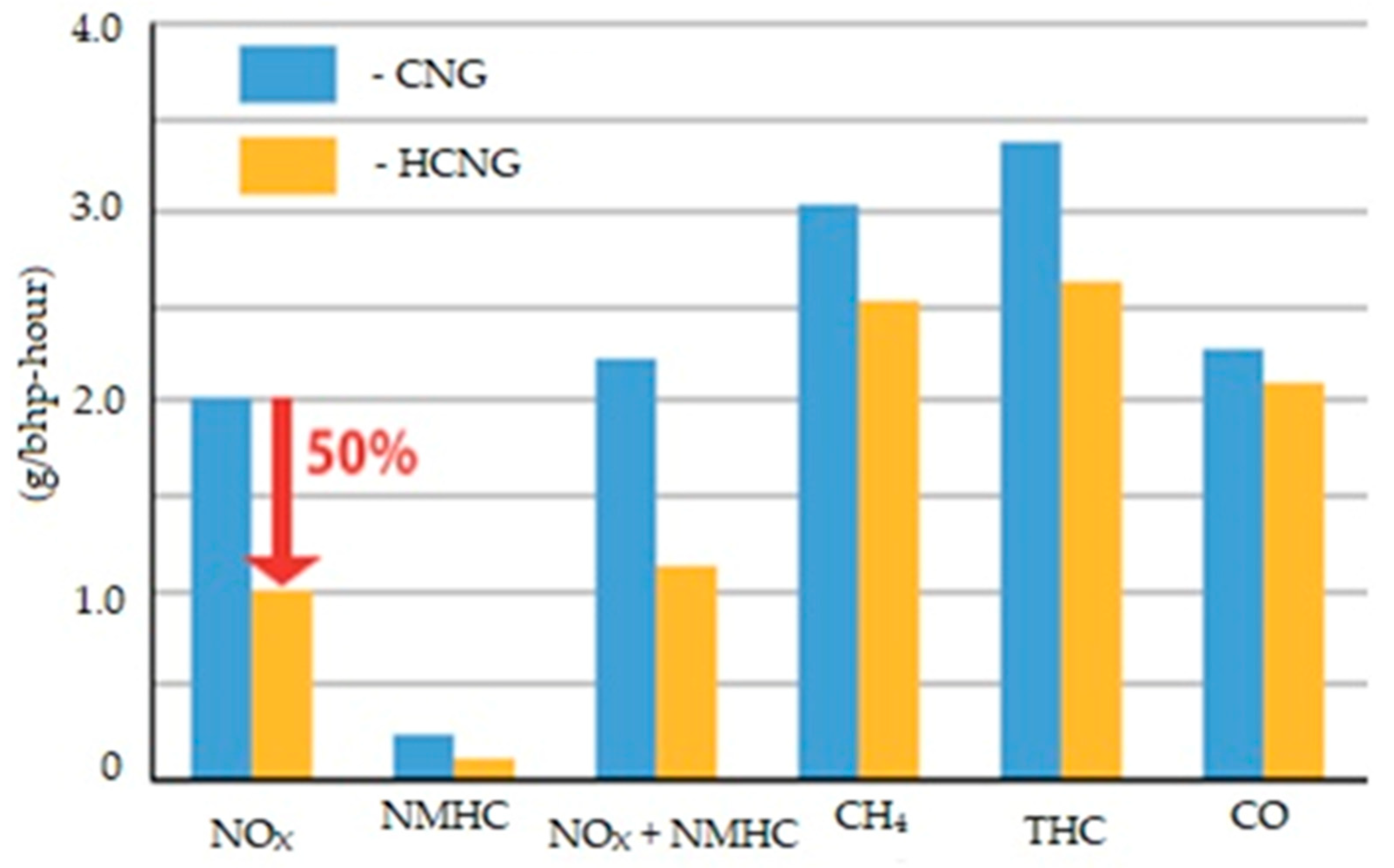
Comparing this fuel with the other mentioned fuels containing an increased amount of hydrogen, HCNG is the only hydrocarbon fuel that has the potential to efficiently distribute and utilize hydrogen in a way that allows for minimal GHG emissions when it is used in an ICE without negative consequences for that engine. The production process for this fuel is extremely simple and not energy expensive, with the energy intensity of the production process being the primary issue in achieving a low carbon, hydrogen-based fuel, even when it is green hydrogen [14]. Using HCNG in the existing CNG distribution infrastructure is not very expensive, and the cost of compressing hydrogen to add it to CNG is only a tiny fraction of the cost that would have to be incurred to distribute pure hydrogen independently.
For this reason, the next section of the article will provide a more accurate explanation of the physical and chemical properties of HCNG, allowing for its effective use in an ICE. Many of them can be found in various sources—including those quoted in the article—however, all the graphs developed in this article are based on our calculations carried out to determine the properties of this fuel based on the components of pure hydrogen and NG most commonly available in the native territory country of the authors of this article, i.e., Poland, where other researchers determine NG parameters as in [158].

3. Results

The results in the article are the developed properties of HCNG fuel based on data collected in a literature review on the fundamental properties of hydrogen and natural gas. Most properties have been visualized using charts in which the functions are represented by two curves representing the extreme (the highest and the lowest) values of the given variable. The Results section consists of smaller subsections in which various properties of hydrogen and methane mixtures will be discussed.

3.1. Basic Properties of HCNG

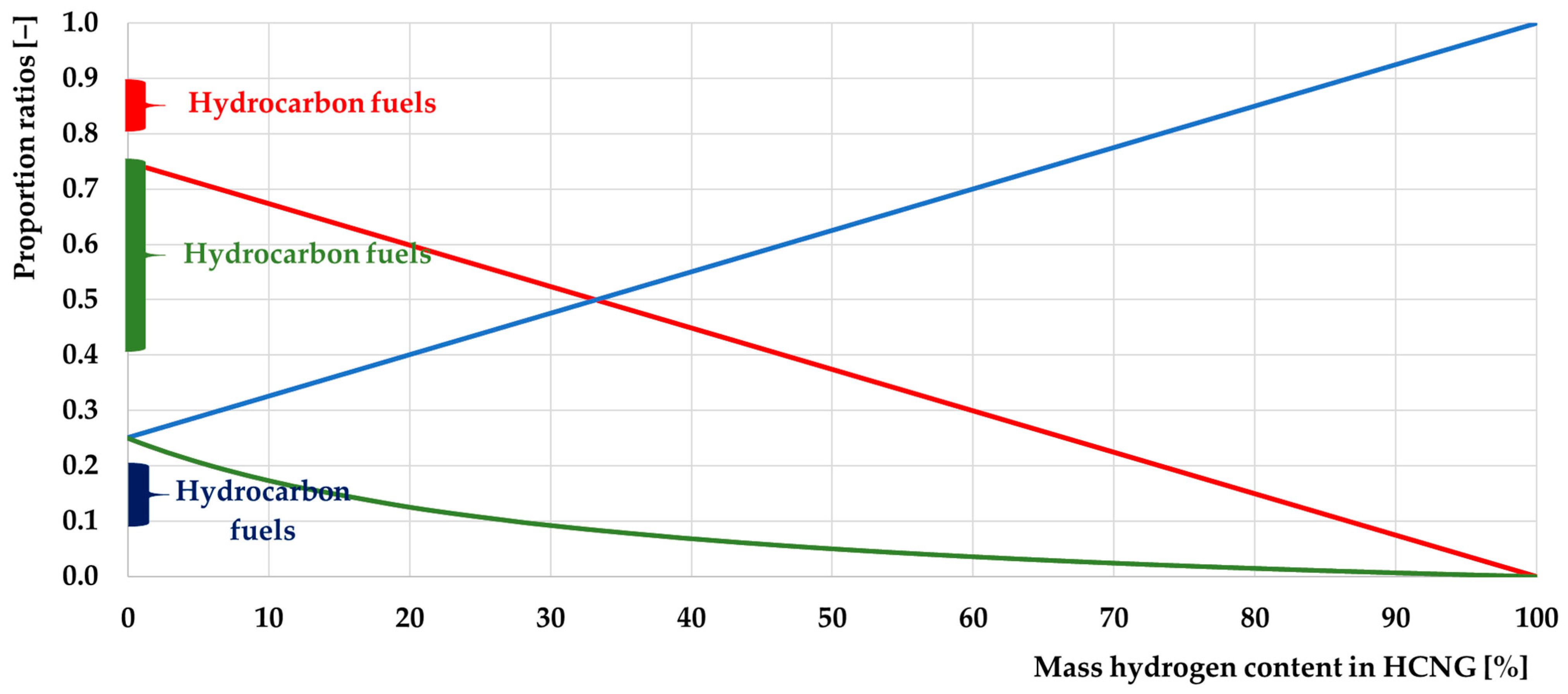
This section of the present article will describe the properties of hydrogen and NG that affect selected HCNG properties relevant to using this fuel in a DF CI engine. The fuel itself is a mixture of hydrogen and NG in a proportion that allows the precise determination of the chemical content of each element in this fuel, as can be seen in the graph in Figure 7 below.
The hydrogen content in the graph in Figure 7 increases proportionally, directly to its content in HCNG, while the carbon content decreases. Based on these data, it is possible to calculate theoretical values of carbon dioxide emissions during the combustion of a given fuel composition. The ratio of hydrogen and carbon atoms in HCNG fuel changes non-linearly.
Due to the great potential of this fuel to distribute green hydrogen in the future, it is also essential to focus on the effect of hydrogen on the properties of this fuel. Although the properties of both gases are essential for this fuel, the properties of H2 itself can be more easily determined than those of NG, whose composition is highly dependent on its source and purification method. This has already been described in detail in an article written by the authors [14]. At the same time, the relevant properties of H2 require further explanation, as its concentration in HCNG can be altered, and its influence on the properties of this fuel can be modified depending on how it affects the operation of combustion engines. The basic properties of each are summarized in Table 2 below, where the key ones allow an understanding of the differences between these gases and their sources and the literature sources.
As can be seen, these fuels share many differences, but more significant are the differences in the data available from different sources. There are many other properties and differences between these fuels, which are easy to find in research articles in familiar, publicly available sources. The extreme values from Table 2 above were used for further calculations, allowing us to determine the range in which the Polish HCNG fuel properties may be. Table 2 will allow for the further analysis of the properties of the HCNG fuel, and the values shown in the table will allow for a better understanding of the characteristics of many HCNG properties.
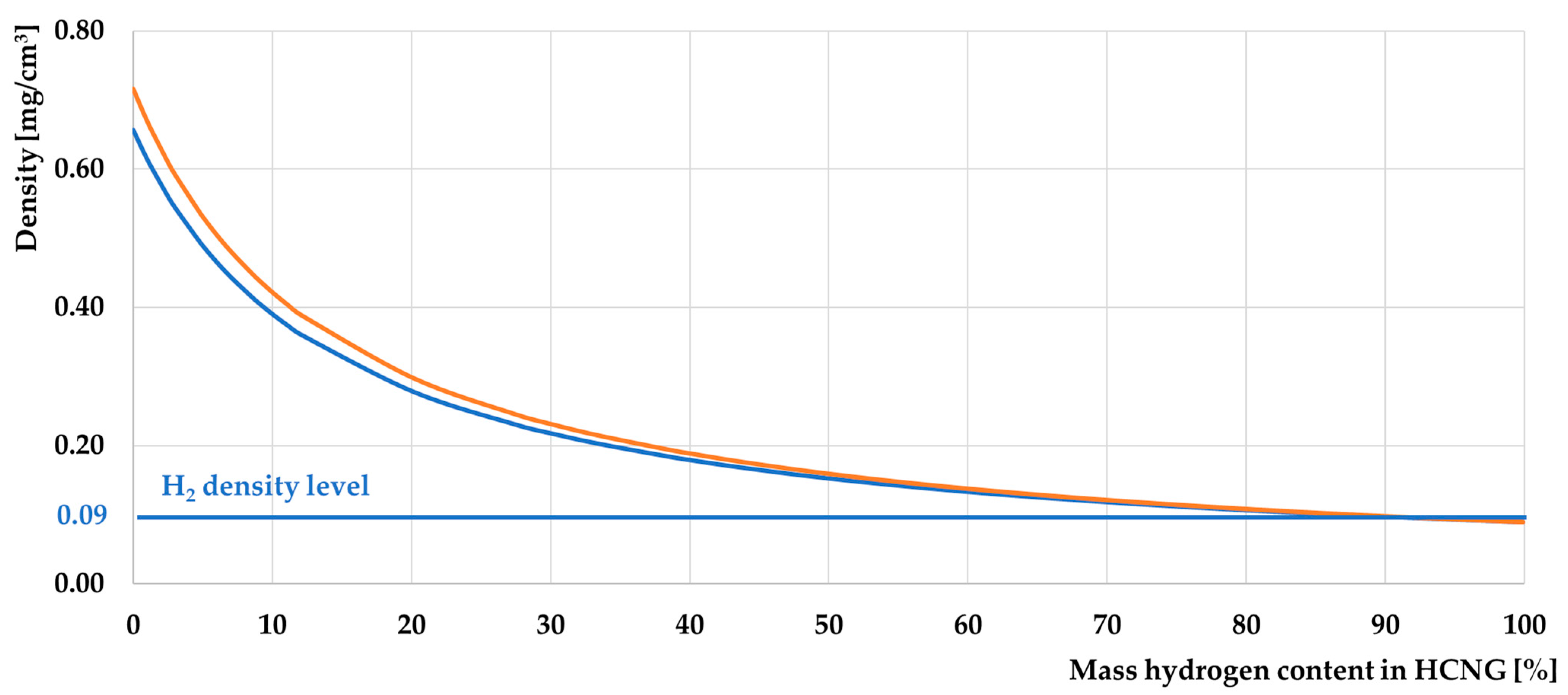
When developing the effect of hydrogen on the properties of HCNG, this significantly impacted the results, as will be seen in many graphs. The most important differences are the calorific value and the densities of both fuels, which influence the energy-type density of both fuels. The effect of hydrogen on HCNG has the most significant impact on the fuel’s density and energy density, as hydrogen, which has an order of magnitude lower density than NG, “dilutes” the fuel energetically as its share increases. The graph in Figure 8 shows the variation in hydrogen density with the hydrogen content of HCNG.
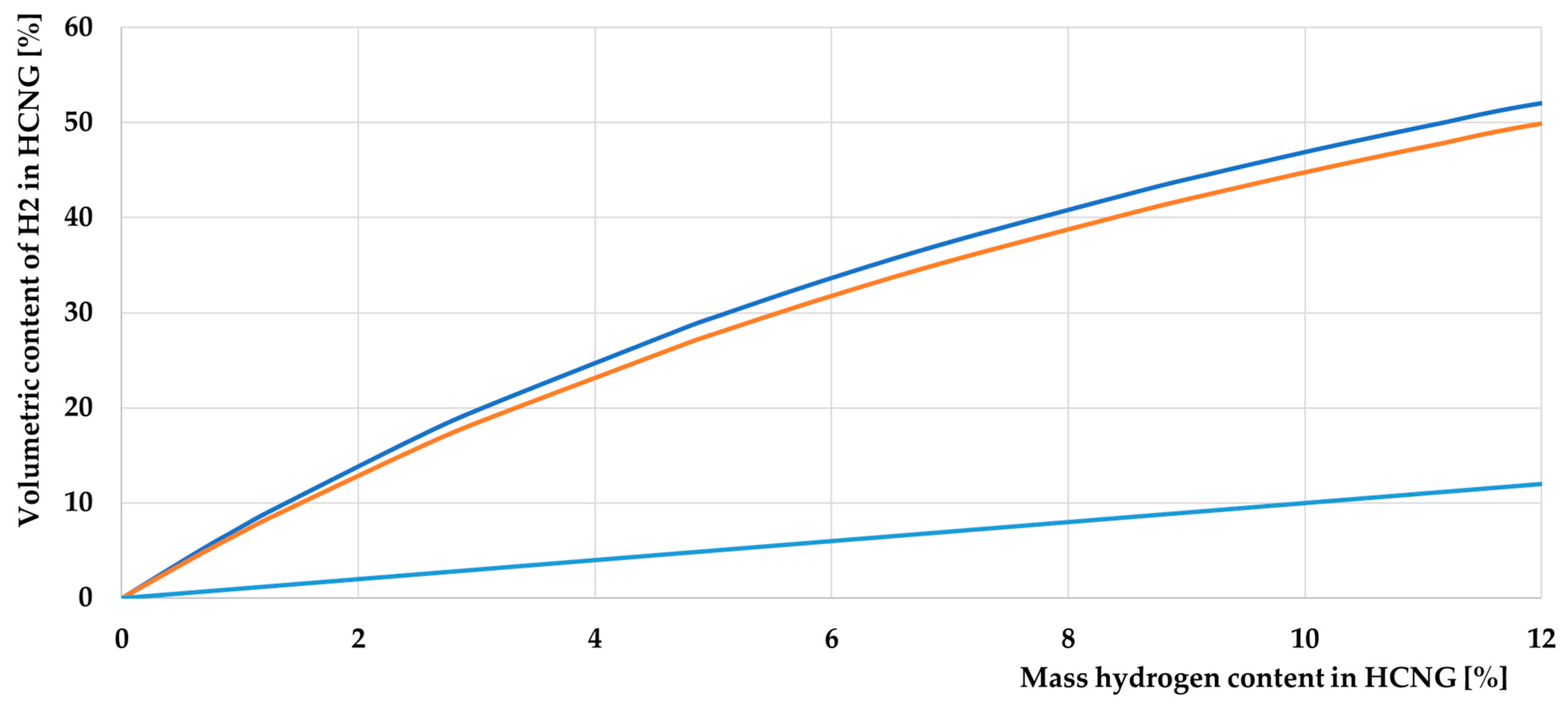
The properties of HCNG are similar to those of pure CNG, but the addition of hydrogen affects several other parameters. Compared to CNG, hythane has a higher calorific value, but the volumetric energy density decreases as the hydrogen content of this fuel increases. To better understand this effect, it is necessary to look at its variation in the extent to which it is currently possible to distribute this fuel via the existing infrastructure responsible for CNG distribution. To look at the function for the hydrogen content range HCNG0—HCNG50, it is first necessary to understand the differences due to different values in the various data sources. The graph in Figure 9 below gives the volumetric hydrogen content as a function of its mass content, which is an essential determinant for calculating the volumetric and mass hydrogen content in HCNG.
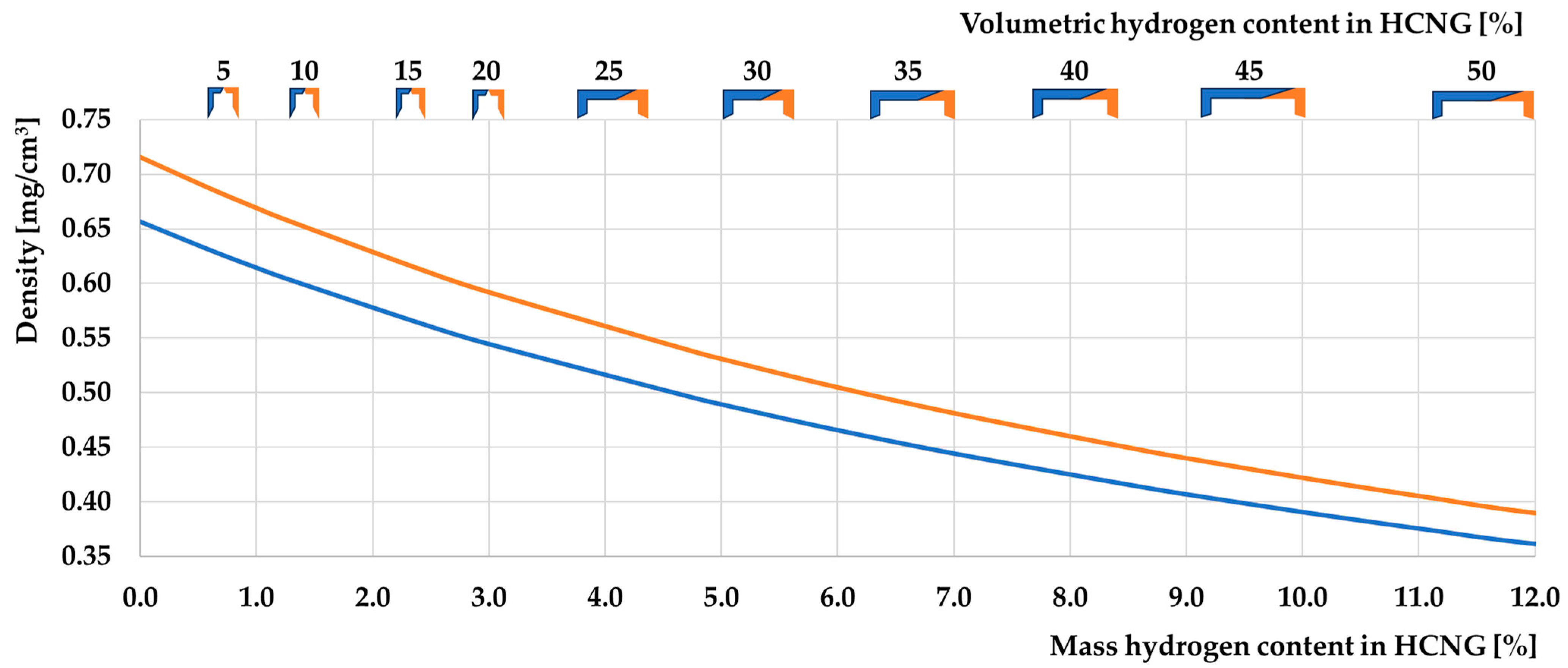
As can be seen, the hydrogen content by volume of about 50%, corresponding to the HCNG50 fuel, corresponds to about 12% of the hydrogen content by mass in HCNG. In this range, the changes associated with the addition of hydrogen are the most intense but will represent both changes in this and the full range of hydrogen content in HCNG, from 0 to 100% of the mass hydrogen content in the fuel. In the case of density, exceptionally, the most significant discrepancies arise from the three sources [161,162,166] describing the NG/methane and hydrogen densities. The differences between the sources are not large but have a very significant effect on the other properties of HCNG, as seen in the following graph. It is good to see those charts in the medium zoom, with a 0–12% hydrogen mass content range like below. The graph in Figure 10 shows the dependence of the HCNG density on the hydrogen content of HCNG in the range of hydrogen mass concentrations from zero to 12, i.e., up to about 50% of the volume of hydrogen content.
The density of HCNG in the range from 0 to 50% hydrogen by volume in HCNG decreases in direct proportion to the hydrogen content of the mixture. In this range, a proportional decrease in density is evident. It is essential to emphasize in the introductory section describing the selected properties of HCNG the influence of the quantum properties of hydrogen on its physical properties. The most important of these is the effect on hydrogen density. In the case of this fuel, its quantum properties significantly impact its use as a fuel. The hydrogen atom comprises one proton and one electron, making it the simplest chemical element. Its physical and chemical properties result from the strong interaction between the proton and electron and the orbital structure of the electrons. Because of this atom’s simple structure, this fuel’s physical properties are influenced by the behavior of the proton and electron of this element [169], which will be described in the following subsection below.

3.1.1. Quantum Hydrogen Fuel Properties, and Why Is There no “HLNG” Fuel?

Due to the problem of the quantum properties of hydrogen described in this sub-section, no technical solutions are currently used to prepare “HLNG” fuel for distribution. The worst problem is the methane melting point temperature, which is higher than the hydrogen evaporation point temperature. This difference makes it impossible to make liquid the blend of these substances at one time and place, and further use of this fuel could be possible only when all of this fuel is heated and evaporated [170]. The indication is the stratification of HCNG during liquefaction and fuel evaporation due to the different liquefaction temperatures of the two components. This would lead to several adverse phenomena, so it should be remembered that hydrogen–methane mixtures can currently only be distributed in compressed form because of methane and hydrogen properties [171,172,173]. In the liquefaction process, LNG is purified to about 99% of methane because other substances have different liquefaction temperatures. Hydrogen needs much more energy to be used in liquid form than methane. In this case, for fuel supply in hythane on ships, it would be possible only to transport both fuels independently or generate hydrogen on board the ship. Such installations will be justified when emission regulations begin to urge shipowners to reduce GHG emissions below the level that can be met by using hythane to fuel marine engines. NG transported on large ships is always stored in liquid form, i.e., as LNG. For various reasons, as described below, mixtures of NG and hydrogen are not stored in this form. In addition to the different condensation temperatures of methane and hydrogen and the density that makes it difficult to mix these fuels in liquid form, the problem is also caused by the straightforward structure of hydrogen atoms, whose quantum properties have an enormous impact on their physicochemical properties.
Molecular hydrogen (H2) exists in two forms with slightly different physical properties—orthohydrogen and para-hydrogen. The form of occurrence depends on the proton spins orientation in the hydrogen atoms. Orthohydrogen molecules have parallel spins, while para-hydrogen molecules have antiparallel spins. In other words, in orthohydrogen, the spins of the protons are directed in the same way, and in para-hydrogen—the opposite is true. The chemical properties of both hydrogen forms are the same but differ significantly in thermodynamic and physical properties. The content of individual hydrogen gas forms strictly depends on the temperature—the closer it is to absolute zero, the higher the content of hydrogen para-hydrogen in such cooled hydrogen. The orthohydrogen to para-hydrogen ratio is already three to one at room temperature.
Table 3 clearly shows the differences in the physical and thermodynamic properties of different forms of hydrogen [3]. It differs significantly in density in various forms—pure para-hydrogen has a density of about 22% greater than that of hydrogen in the surrounding air; the specific heat of para-hydrogen is also several percent higher, while the entropy of para-hydrogen is less by about 9%. The other properties are already similar to each other.
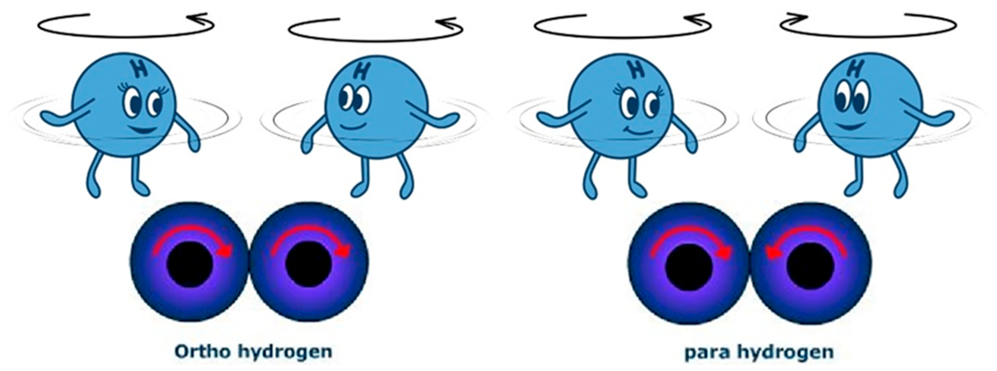
There are possibilities of changing orthohydrogen into hydrogen para-hydrogen with the help of catalysts, such as paramagnetic, or by lowering the temperature of hydrogen [174]. However, these are long-term processes, as a result of which heat is released (at the level of 527 J/g H2). The “instantaneous” condensation of ordinary hydrogen (75% orthohydrogen and 25% para-hydrogen) will result in liquid hydrogen having the exact proportions of both forms of hydrogen as in hydrogen under normal conditions. Only under the influence of long-term hydrogen storage in liquid form will the ortho–para conversion occur spontaneously, up to the achievement of over 99.8% of para-hydrogen content under the achieved equilibrium conditions. In condensing the hydrogen process into a liquid form, the standard procedure is to convert the hydrogen into a stable quantum form of para-hydrogen [85]. Para–ortho conversion is a fundamental phenomenon in storing LH2 to maintain the correct temperature, preventing excessive evaporation [175]. The heat released changes with the temperature of the liquid hydrogen and increases as the temperature of the converting hydrogen decreases. Hence, difficulties in storing hydrogen in liquid form may arise because the heat of hydrogen vaporization (447 J/g H2) at low temperatures is lower than the heat of ortho–vapor transformation and causes evaporation of the condensed hydrogen and liquid losses even in the best-insulated tanks. Various types of catalysts have been used to convert ortho- into para-hydrogen before it is stored [174]. The thermal effects of the ortho–para hydrogen conversion may also have an impact on safety because the rapidity of this exothermic reaction may lead to such a “rapid” increase in temperature that it may lead to an increase in the pressure of the hydrogen gas accumulated in the tank [176]. The heat of this conversion is 1.5 times higher than the heat of the vaporization of hydrogen (703 kJ/mol). The evaporation process can lead to boiling liquid expanding vapor explosion (BLEVE), directly related to ortho–para-hydrogen conversion [177]. Figure 11 below shows the cartoon depiction of the quantum hydrogen phenomenon compared with the schematic representation of hydrogen atoms.
The rotational orientation of interconnected diatomic hydrogen atoms affects their chemical and physical properties. These are important from the point of view of using clean hydrogen as a fuel. This significantly impacts the ability to store hydrogen in liquid form because, in normal conditions, most hydrogen atoms “want to rotate in the same way”, like in the left part of Figure 12, where the spin of both atoms is similar. Intensive cooling of hydrogen causes the spin change to be visible on the right part of Figure 12. The change in spin involves a change in energy, which makes it challenging to keep hydrogen in a cryogenic state because, even in the cryogenic condition, hydrogen atoms gradually change their spin. Figure 12 was created to make the spin idea more understandable and accessible to the reader.
We can use only hydrogen with antiparallel proton spins to increase the energy density from a unit of hydrogen volume. The temperature at which a mixture of the two forms of hydrogen or various types of catalysts induces the conversion can be used to convert orthohydrogen into para-hydrogen. Table 4 shows roughly how the content of para-hydrogen in molecular hydrogen changes with the change in its temperature.
The conversion is not immediate and takes a certain amount of time. However, its pace is sufficient for over 50% of the liquefied hydrogen to evaporate within a dozen or so days of the condensation. Formula (1) [59] is used to determine the content of para-hydrogen “x” in liquid hydrogen after a sufficiently long time “t” at the initial concentration “y”.
x = (y + 0.00855 × t)/(1 + 0.00855 × t)
It can be calculated that it takes almost a thousand hours (over five weeks) to increase the concentration of para-hydrogen to over 90%. If the liquefied hydrogen were consumed quickly, it would not need to be converted to para-hydrogen. However, if the hydrogen fuel were to be stored for several days or weeks, most of the liquefied hydrogen would evaporate due to the conversion, and only the continuous removal of heat from it would keep the fuel liquid. In the case of joint storage of liquefied hydrogen and methane, it would generate additional problems that do not occur in the storage of LNG, and one of the assumptions for the creation of the hythane fuel was the possibility of using standard installations used for NG for its distribution.
To solve the problem related to the conversion of hydrogen after its condensation, special catalysts are used to convert orthohydrogen into hydrogen vapor quickly and at a temperature that does not lead to the condensation of hydrogen molecules. In most cases, the hydrogen molecules are first brought to a suitable temperature and then allowed to contact the catalyst by the hydrogen molecules. Molecules adsorbed on the catalyst surface break away from it as a parahydrate. Catalysts can be oxides of various metals or activated carbon in the form of granules with a diameter of 1 mm. The reaction is carried out during the condensation of hydrogen, i.e., at temperatures below 300 K. If, however, the hydrogen already converted to para-hydrogen had not condensed, it would remain in its form even when brought back to room temperature. The reconversion of hydrogen to a specific ratio occurs only at a temperature of about 1000 K in the presence of a platinum, nickel, or tungsten catalyst. The transformation also improves the parameters desired for the fuel, even for the gaseous form of hydrogen. However, the temperature at which most of the transformations are carried out is closer to the condensation temperature than to room temperature [3].
Installations of this type designed for the preparation of hydrogen to store it together with NG have yet to be commonly and accessibly described in free scientific publications [179].

3.1.2. Characteristics of HCNG Properties Relevant to Its Use as Engine Fuel

Compression ignition (CI-diesel) engines are used in various applications, including cars, trucks, buses, construction and agricultural machinery, shipbuilding, industry and generator sets, or polygeneration. Their ease of adaptation to DF operation allows those engines to be adapted to run on multiple fuels. It enables most industries using ICEs to switch to alternative engine fuels with lower greenhouse gas emissions. CI engines are highly efficient, and much more economical than spark ignition (SI) engines, and their versions operating in DF mode are even more efficient.
In single-fuel CI engines, fuel is injected directly into the combustion chamber, where compression and heating of the fuel–air mixture to a high temperature leads to CI. Using a second fuel—a low-reactive and high-octane number fuel—in a CI engine allows for increased use of the entire space above the piston of this ICE. The combustion starts after the self-ignition of high-reactive, high-cetane fuel—is injected directly into the combustion chamber. The best DF engines are reactivity-controlled compression ignition (RCCI) engines, where efficiency is even higher [180,181,182]. This method of fueling and combustion is accurately described in [183], where the importance of using these types of engines is well explained. It is essential to know that high-methane NG, hydrogen, and ammonia fuels have the same high octane number value at 120–130 [184]. All CI ICEs can be modernized to DF combustion [185]. Those engines are some of the most considerable CO2 emitters in the world [132]. Hydrogen, in addition to fuels, would allow companies and industrial plants that use ICEs to produce energy to reduce GHG emissions. This translates into the company’s reputation and the possibility of receiving subsidies for developing and constructing this type of installation. This is important because HCNG usage in this engine type requires specific fuel properties and values. HCNG and hydrogen can be used successfully in DF engines [186]. Hydrogen and HCNG, with a large amount of this fuel, have one characteristic value at a much higher level than other engine fuels. That value is its calorific value; one of the most important parameters characterizing a fuel is its calorific value. The graph below shows its value as a function of the mass content of hydrogen in HCNG.
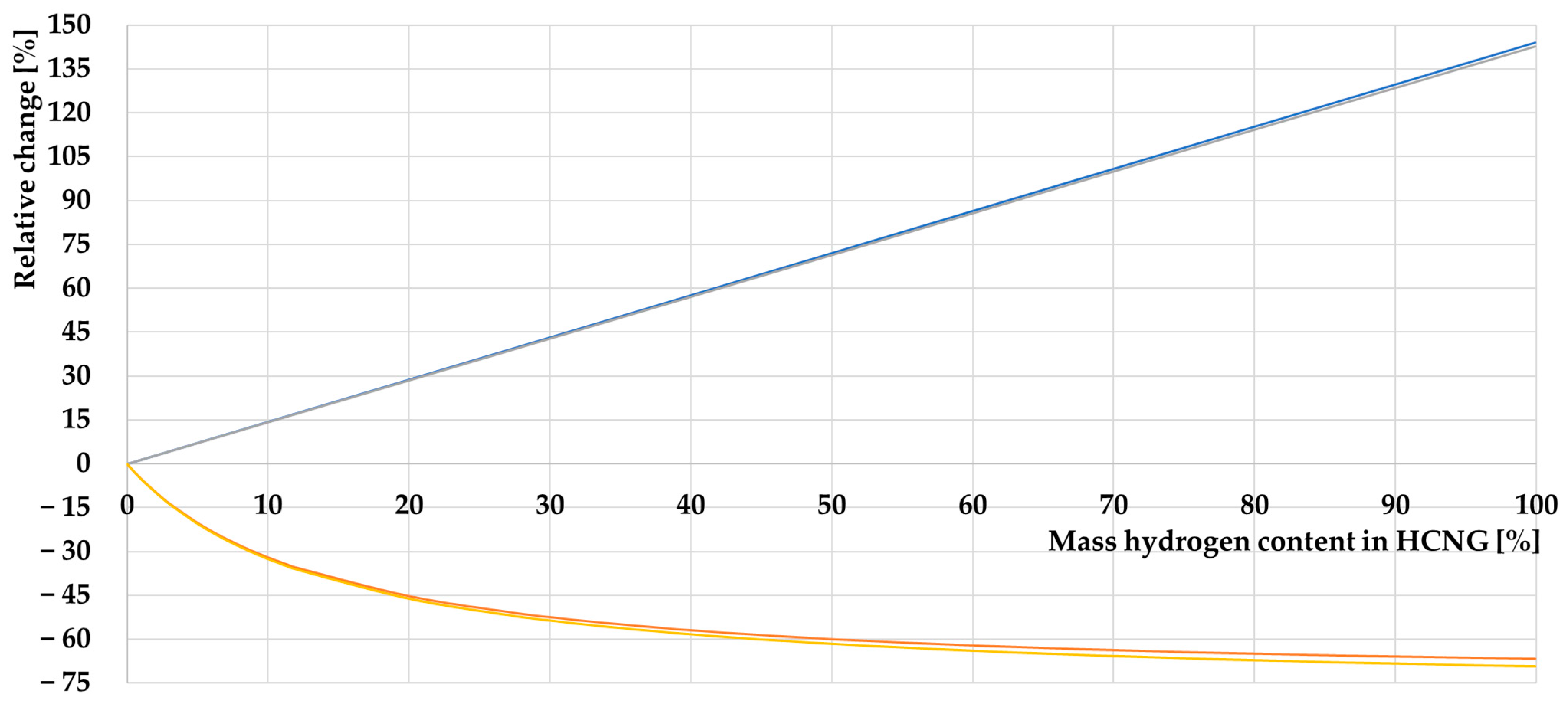
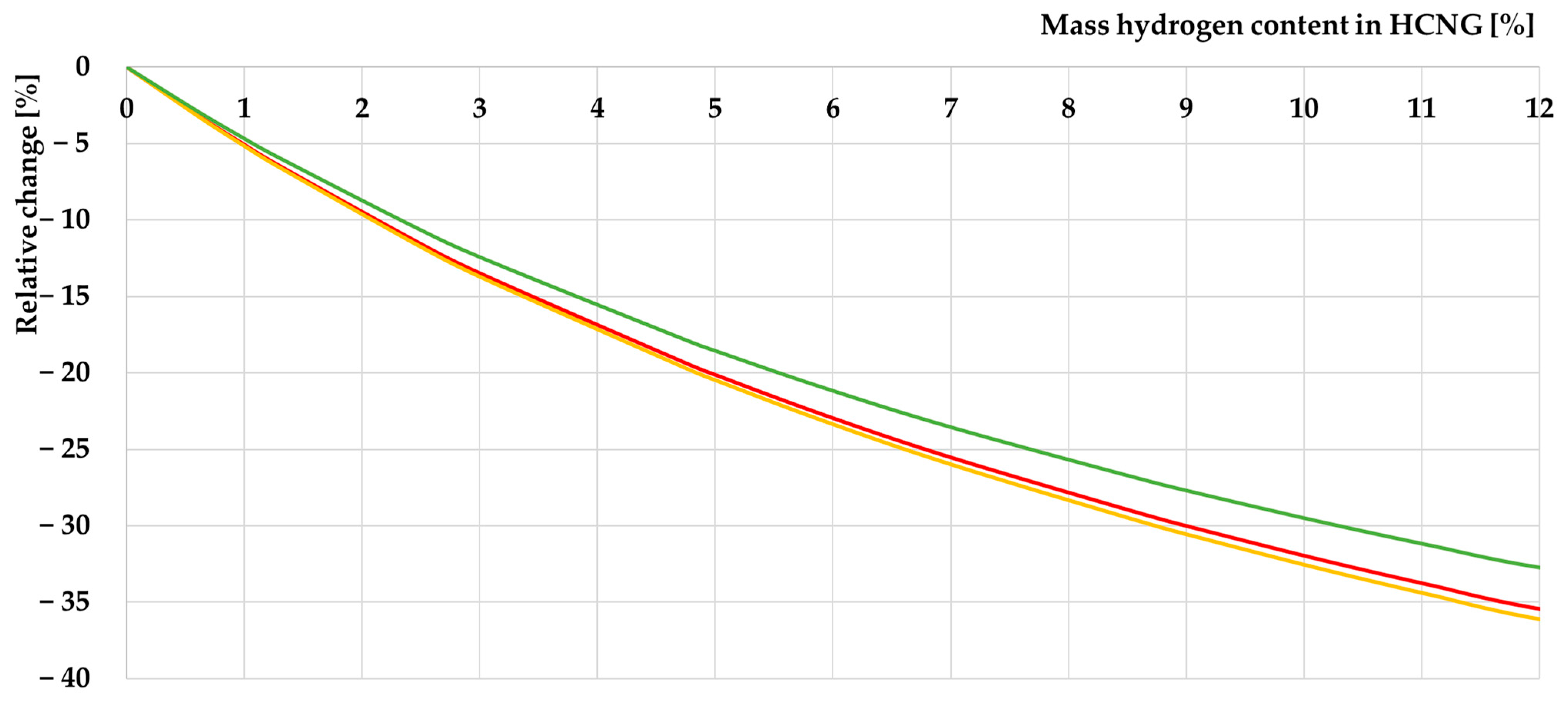
This value characterizes the amount of heat energy obtained from fuel combustion without the energy benefits associated with energy recovery from condensation. In the case of liquid and solid fuels, this value is, under normal conditions, adequate for the suitability of the fuel in question from the point of view of its use in mobile units due to its similar volumetric calorific value [187]. Gaseous fuels pose a problem, as the amount of chemical energy contained per unit volume depends on the conditions under which they are found. The lower curves in Figure 12 represent the volumetric energy density of HCNG, which, in contrast to the calorific value seen in the upper two lines, is not uniformly proportional to the mass content of hydrogen in HCNG. This can be seen more clearly in the following close-up shown in Figure 13:
The graph in Figure 14 shows the volumetric chemical energy density contained in HCNG from HCNG0 to HCNG50. The higher the decrease in energy density, the lower is the hydrogen content of HCNG. Therefore, the most significant effect of adding hydrogen is on the pure CNG to which it is doped. If HCNG is to be distributed via a pressure tank system designed for CNG, it significantly reduces the amount of energy stored in that tank. In the case of vehicles, this translates into a reduction in the range of that vehicle, for, in the case of the use of HCNG in vehicles, the limit to the hydrogen content of HCNG is not only its ability to penetrate and corrode metal components but also its ability to store a certain amount of energy in a fuel tank limitation volume. Figure 14 below shows the values of the relative changes in calorific value and volumetric energy density as a function of the mass content of hydrogen in HCNG.
Changes in volumetric energy density, as seen in the graph in Figure 14, are most intense for hydrogen contents up to 30–40% by mass of hydrogen in HCNG. Above this value, the density practically does not change anymore, while the calorific value increases linearly with the increasing hydrogen content in HCNG. Four functions are presented in the diagram in Figure 15; however, in this case, discrepancies in the source values on which the calculations are based do not cause significant differences between the calculated results, so the functions practically coincide. Due to the significance of the effect of hydrogen content on the volumetric energy density of HCNG, the graph below shows two functions presenting extreme values of calculated volumetric energy densities as a function of hydrogen content in HCNG from HCNG0 to HCNG50.
The changes in volumetric energy density calculated based on the two sources presenting extreme values do not differ significantly from each other, and differences are only apparent at higher hydrogen contents in HCNG. More attention should be paid here to the fact that diluting CNG with hydrogen to the level of fuel HCNG50 already causes a drop in energy density by more than 35%. In such a case, HCNG40 fuel already has 1/3 less energy per unit of its volume than CNG stored under the same conditions. HCNG25 already reduces the energy density of the fuel by 1/5.
It should be borne in mind that in the case of high contamination of a base fuel such as CNG with non-combustible chemical compounds such as nitrogen, the addition of hydrogen will not reduce the energy density of HCNG as intensively as in the case of the almost pure methane [58] seen in the diagrams. The nitrogen content in NG can be up to 21.5% [188], which lowers its calorific value by more than 1/5. An example of the effect of hydrogen on highly nitrogenized NG is shown in the additional curve in Figure 16 to illustrate the reduced effect of hydrogen on lowering the volumetric energy value of HCNG.
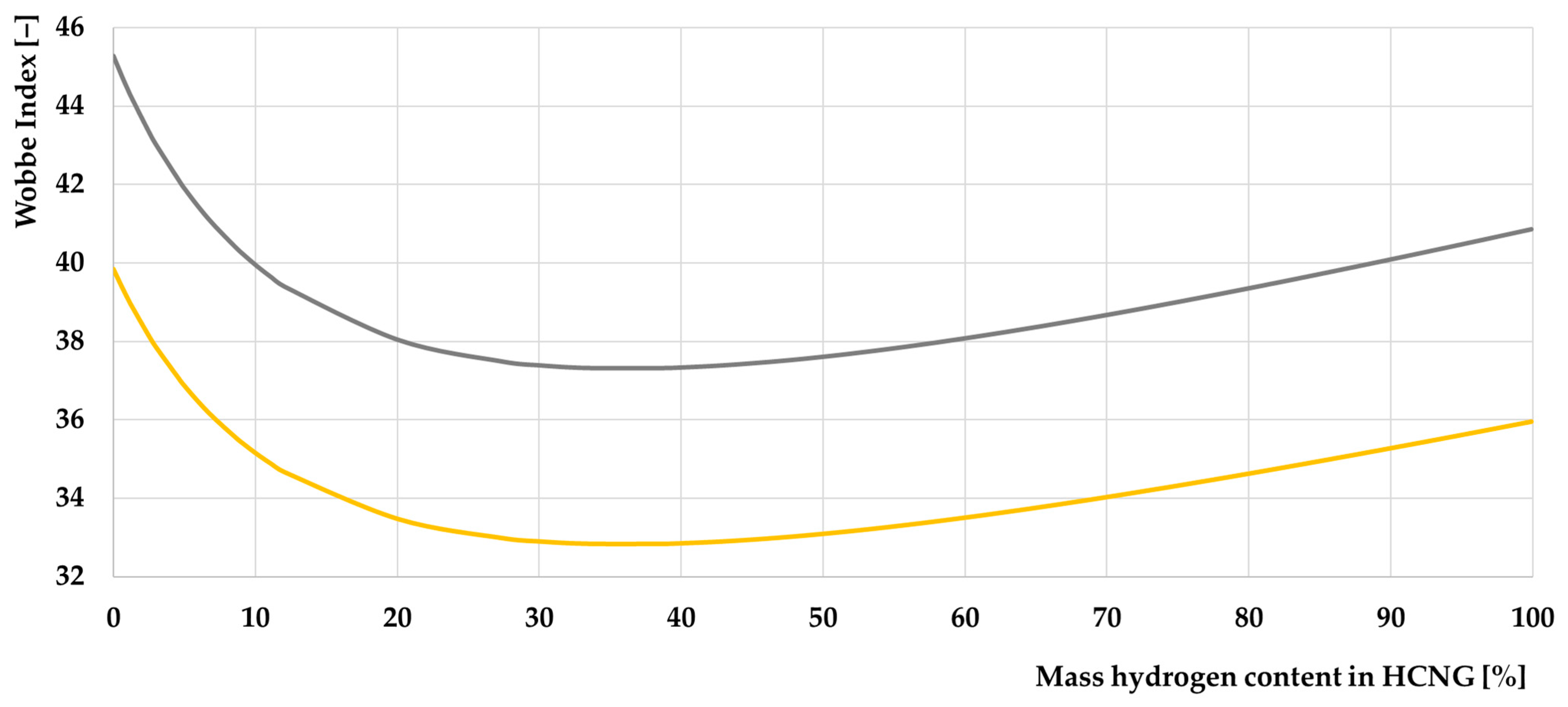
Equally important from the point of view of the user of gaseous fuels is knowledge of the Wobbe index of a given fuel. Its value represents the energy density of a given gaseous fuel to its relative density—relative to the density of air [189]. This value can indicate the interchangeability of fuel gases with different chemical compositions of similarity between NG and a specific propane–air mixture [190,191]. The graph in Figure 16 below shows the variation in the Wobbe index as a function of the hydrogen content of HCNG.
Calculated based on [158,161,162,166,168] and compared with values from many other publications [192,193,194] which have different values, however, often within the specified range, where hydrogen has very similar values in all publications and NG does not. It is essential to know that NG has so many different values in the Wobbe index that those charts could look so different in the case of the used source, where some of them [191,195,196,197,198,199,200,201,202,203,204,205,206,207,208,209] are strongly divergent. It can strongly depend on NG’s propane or butane content [210].
The Wobbe index provides information on the properties of the fuel, allowing it to be used in many areas. Its influence on the performance of an engine running on a given fuel is a matter described in the literature [211], and more emphasis is placed on this parameter when powering RCCI engines, in which gaseous fuels will be the primary source of energy in these fuels [211]. Figure 16 clearly shows the differences in the Wobbe index values depending on the source from which the data for the calculations are drawn [191,192,193,194]. In addition, it is essential to note that further analysis of the literature on the subject shows even more significant differences in the value of this parameter to the NG fuel [191,192,193,194], which further confirms the magnitude of the differences in the composition, and thus the physical properties, of this fuel. On the other hand, the course of the Wobbe index as a function of the hydrogen content in HCNG is consistent, with its value decreasing up to a hydrogen content of about 35% by mass of hydrogen in HCNG and then increasing until pure hydrogen is reached. The maximum enrichment of HCNG in hydrogen is also confirmed in [212]. Figure 17 shows the Wobbe index value for different HCNG fuels from 0 to 50% of volumetric hydrogen content in this fuel (0–12 mass hydrogen content in HCNG).
The decrease in Wobbe index values is relatively uniform at hydrogen contents in HCNG of no more than 50% by volume. Both the upper and lower values change similarly. Increasing the hydrogen content in this concentration range, therefore, worsens the magnesium properties of this fuel.
The properties of hythane can be tailored by changing the ratio of hydrogen to NG. The use of hythane can lead to a reduction in greenhouse gas emissions as well as harmful substances. Hythane is safer than pure hydrogen, as pure hydrogen is highly explosive, while HCNG is less explosive due to its high methane content [155]. Modeling has shown that the explosive properties of hythane are slightly higher than methane’s, and for both these fuels, the explosion pressure is much lower than for hydrogen [213].
The explosive properties of HCNG must be determined based on experimental tests, as the knowledge of values characterizing the individual component fuels—hydrogen and NG—will not allow the values for HCNG at different hydrogen contents to be worked out by calculation, as they do not change arithmetically. Fuel stratification may occur when the fuel mixes with air, so the parameter characterizing methane may become more critical in some areas and hydrogen in others. For this reason, the parameters for both fuels are essential and will be presented here, and HCNG should be regarded as a fuel with explosive potential in the full range between these values if no binding tests are carried out in this field [214].
The explosive limits of hydrogen in air are 18.3% to 59% in volume [164,215,216]. Explosive concentration limits are described [217] as a range from 4% to 75% of the hydrogen content in the air [218]. The extensive hydrogen explosion range, flame wave propagation speed of 3.15 m/s [219] (in another publication, 1.7 m/s [220]), the accumulation of vapors in the upper parts of confined spaces, and a high capacity for diffusion make it necessary to use a multilevel hydrogen detection system (aspiration, ultrasonic, and flame detectors), as well as ventilation systems enabling the removal of vapors from explosive atmospheres [164]. The laminar flame speed should be precise, too, but simple calculations are insufficient to obtain correct results; there are simulation results in other research studies [221,222,223]. This value determines the time of the combustion process in the engine. However, in RCCI/HCCI (homogeneous charge compression ignition) and LTC (low temperature combustion) [224,225] engines this parameter does not affect the combustion process [226]. In DF engines, it is crucial to correctly calculate the heat release ratio, which is described in the following sections.
The explosion limits of NG are related to the high methane content of the fuel. The gas forms flammable and explosive mixtures with air. It is lighter than air and accumulates in the upper part of rooms. Ignition or explosion can be caused, for example, by sparks. The description of the gas states that it can form explosive and flammable mixtures with air. “Vapors are lighter than air and accumulate in the upper parts of the rooms. Ensure effective ventilation. Keep concentrations of hazardous constituents in air below permissible exposure levels and explosive concentrations. Do not use open flames. Do not use sparking devices or tools; ventilation and electrical installations must be by the conditions regarding fire and explosion hazards. Protect against static electricity discharges (earthing, bridging)” [227]. Notably, in Polish standards or data sheets for NG as a fuel, its properties are characterized based on the results obtained from testing pure methane. This gives grounds for a similar treatment of HCNG as an explosive fuel, where extreme values developed based on methane and hydrogen tests will constitute the basis for the specification sheets for this fuel. The most critical conflagration hazardous hydrogen and methane parameters are collected in Table 5 below.
Studies on the explosion hazard of HCNG have been conducted by [235,236]. It is worth referring to experimental research on this topic; mathematical calculations will not translate here into innate phenomena that may occur in the case of HCNG. The values calculated for HCNG are averaged values based on the bulk composition of the mixture. To find out the actual data, it should refer to specific research on this topic, which, as described in the conclusions, is insufficient to determine this type of information with high certainty for various HCNG fuel compositions. Values from Table 5 for HCNG mixtures should be measured or simulated in special programs; those values depend on the mixture homogenization, stratification, flow laminarization, temperature, uniformity of heating, and many others that cannot be simulated by simple calculations, which has limited the authors of this article.
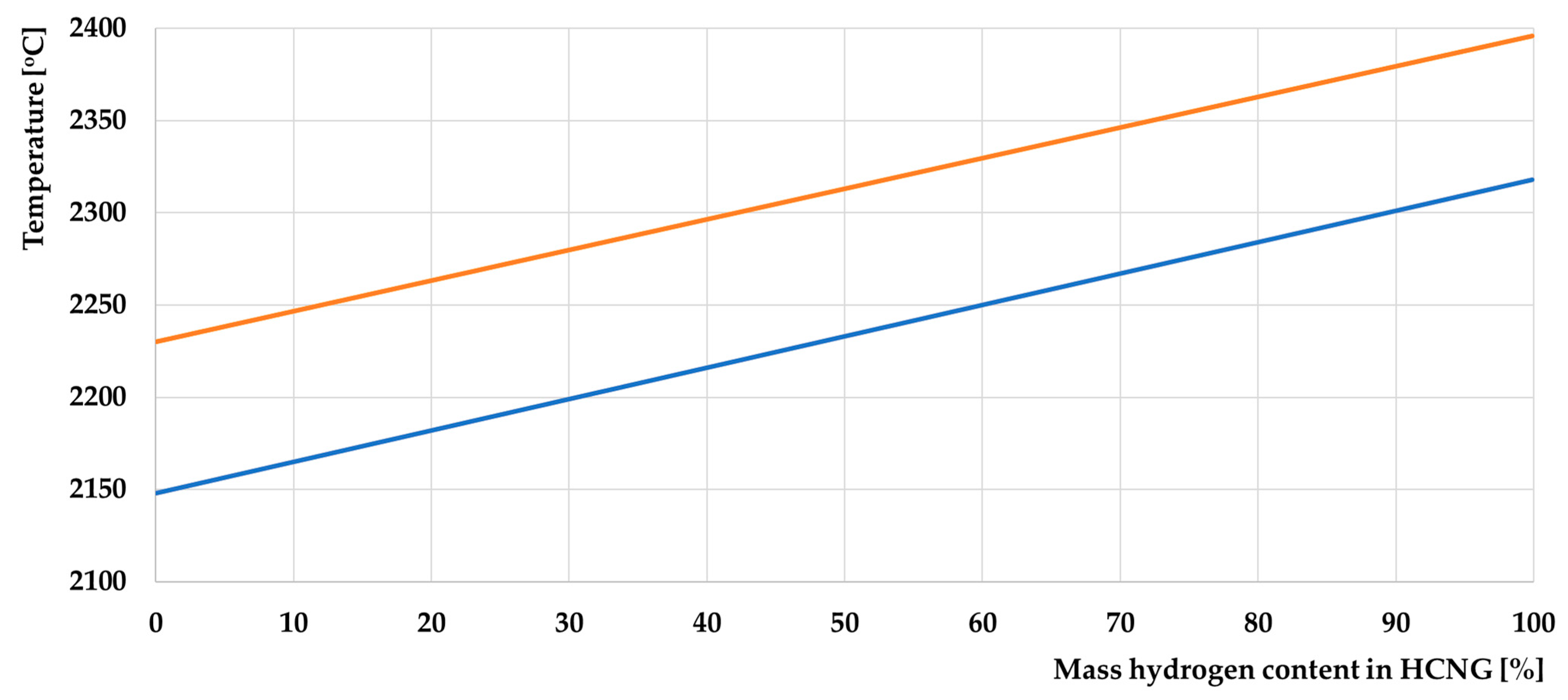
Octane number: HCNG has an octane number close to the LO of pure CNG, which means it can be used in higher compression engines without the risk of ignition ahead of time. One of the challenges of using pure H2 in CI engines is the relatively high combustion temperature of hydrogen, which can produce problems with loss of engine power, as well as increased emissions of nitrogen oxides (NOx). To prevent this, HCNG fuel can be used. Hydrogen has a lower ignition temperature than CNG, so it is easier to ignite the mixture and start the engine at low temperatures with a low ignition energy value, which is also lower for hydrogen and is only 858 K [164]. The combustion temperature is also essential, the theoretical values of which are shown in the following graph in Figure 18.
In Figure 18, there is a uniform, linear increase in combustion flame temperature as the hydrogen content of the fuel increases. However, the differences are not significant, and the value of this temperature is more influenced by the method of determining it (different sources give divergent values) than by the changed hydrogen content of the mixture. It is also worth noting that there is a theoretically calculated temperature, and the actual value in the ICD is usually significantly lower. In addition, it is influenced by the value of the excess air ratio, which is variable in DF engines. Variations in the value of this temperature will, therefore, have little effect on the operation of these engines, as will differences in the values of the minimum auto-ignition temperature of the CNG and hydrogen mixtures [157,164,165].
Several essential parameters for using this fuel in ICEs are not discussed in this article, as it proved difficult to calculate values for the individual hydrogen contents of HCNG fuel, and the relevance of specific parameters relates more to the use of SI engines than CI engines. These include the limiting quenching distance of 0.6 mm for hydrogen (0.64 mm in norm [237]) and 2 mm for CNG [3,238], but it depends on the combustion parameters of the methane–air mixture; the quenching distance for methane or NG could be bigger—2.5 mm for [239], or much more extensive—more than 3 mm for [240,241,242]. The minimum energy required to ignite the air–fuel mixture is 0.02 mJ for the hydrogen–air mixture and 0.29 mJ for the CNG–air mixture [162], or 0.017 mJ and 0.274 mJ [163], so it depends on the data source and research method. In contrast, auto-ignition temperatures ranged from 793 to 858 for hydrogen and 810 to 903 for methane [157,163,164,165] or 537 ℃ for methane and 585 for hydrogen [209]. Another vital piece of information about that kind of mixture is the DDT parameter (deflagration-to-detonation transition), which informs us about the type of combustion that appears in the combustion chamber when a natural gas/hydrogen mixture is burning [243]. This parameter informs us about safety considerations, too. Researchers in [244] said that “Contrary to expectations based on the well-known high reactivity of hydrogen, it turned out that with an increase in, the run-up distance and time of DDT change nonmonotonically,” which proves that without specialized tests or simulations, many parameters determining the hydrogen and methane mixture cannot be determined. In [245], the author shows some parameters depending on whether the engine is fueled by methane or hydrogen. Finding points located “in between” those fuels for HCNG fuel in an algorithmic way may be burdened with too large an error; however, we recommend reading this work and taking into account that for HCNG fuel, these values will be between the values corresponding to the engine operation on methane and hydrogen. A good example is the ignition delay of diesel fuel as a function of the excess air ratio in the atmosphere of a fuel–air mixture. The fuel could be methane, hydrogen, or other low-reactivity fuels [245].
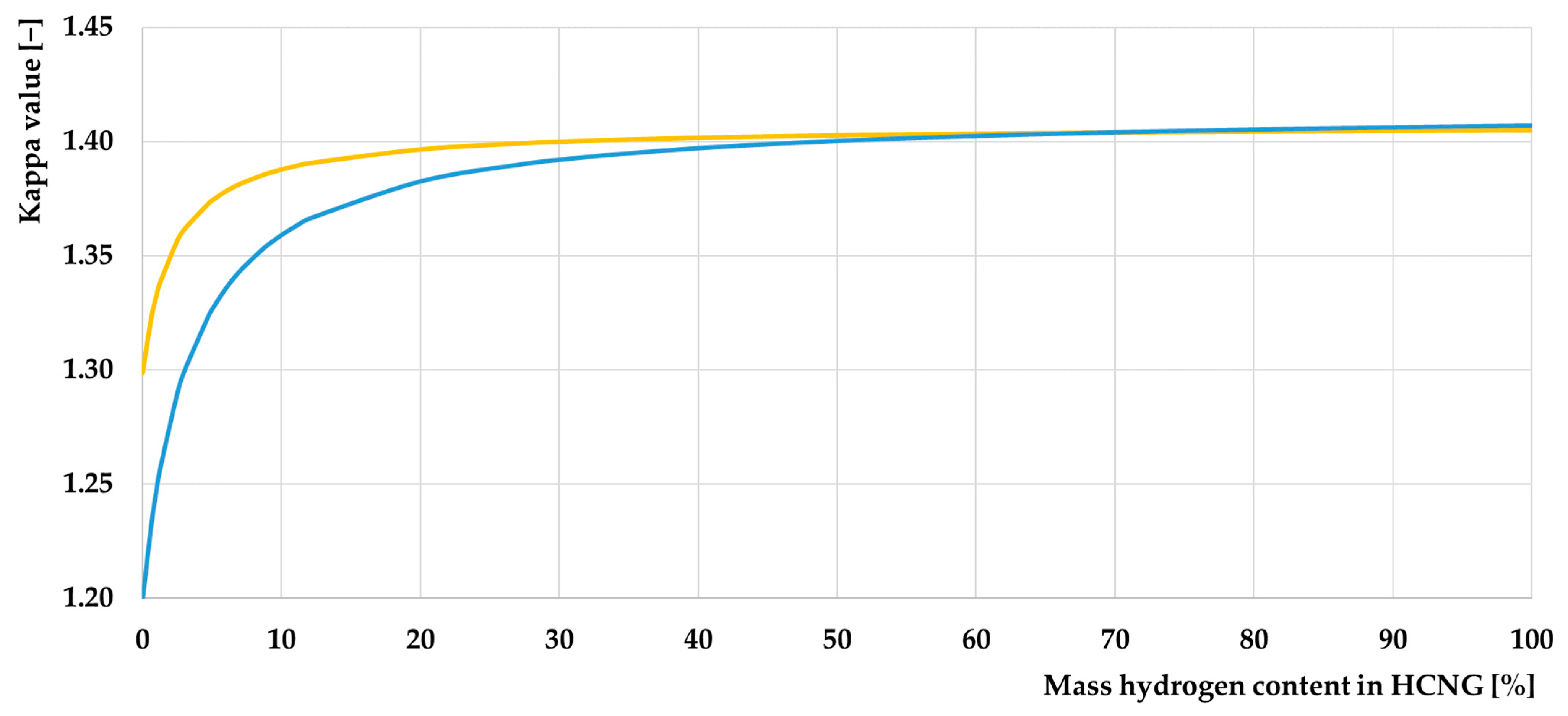
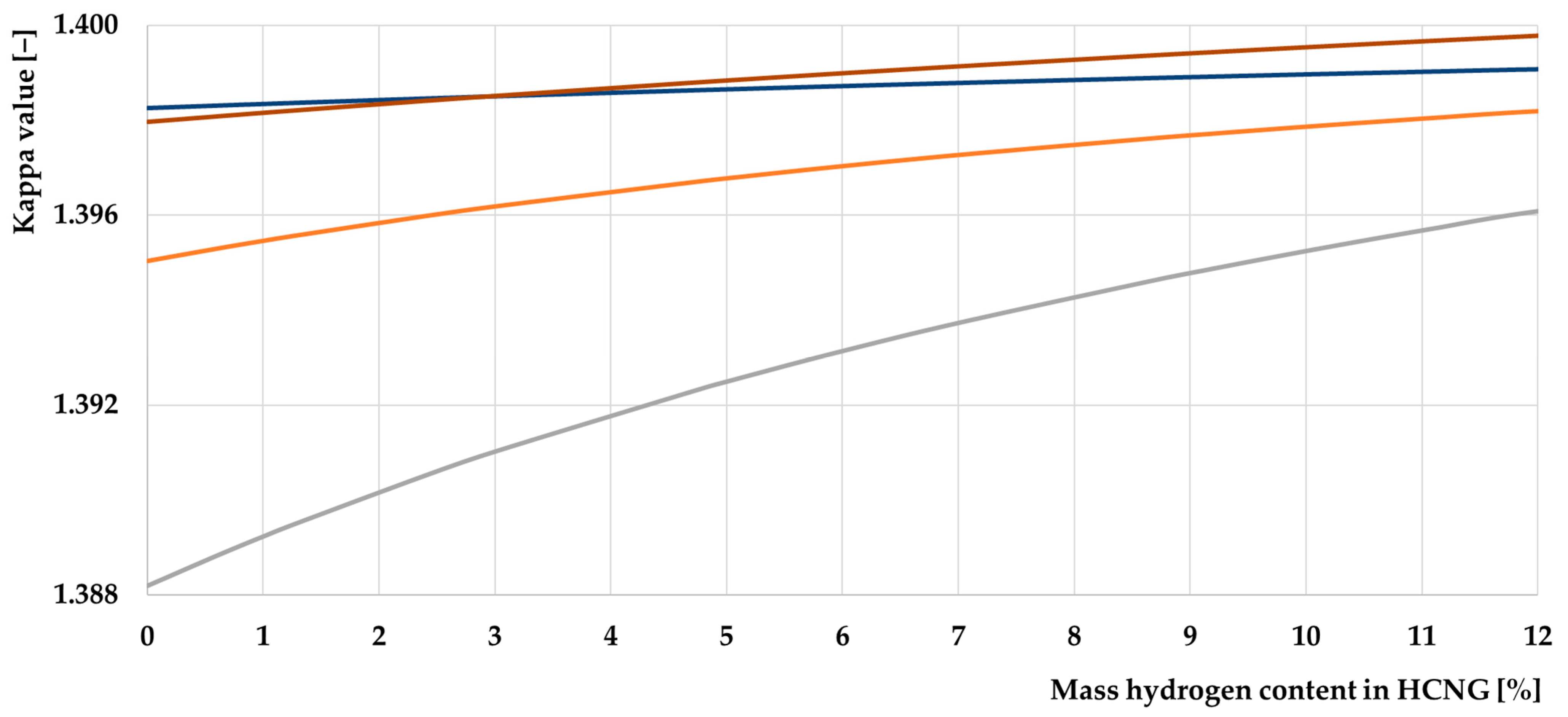
However, important from the point of view of the use of a given fuel in an ICE is the kappa coefficient, also known as the adiabatic exponent, defined as the ratio of the specific heat of a gaseous fuel at constant pressure to the pressure at constant volume [246]. Its value, calculated from changes in the specific heat of the mixture, can be seen in Figure 19.
The calculated values are based on [247,248,249,251,252,253], and all were reported with the original Kappa values of substances [255] and calculated by the chemical formulas from [256]. They agree with the ranges in which these values can be found. Hydrogen, a two-atom gas, mixed with methane, a multi-atom gas, leads to a change in the specific heat of this mixture [257]. A change in the specific heat defined at constant pressure and the specific heat defined at the constant volume of the mixture leads to a change in the adiabatic exponent of that mixture [258]. The kappa value will also depend on the temperature at which the compressed/heated substances are located [259,260,261].
The adiabatic coefficient directly affects the theoretical efficiency of an ICE [262]—both that of a SI engine [263,264] (theoretical efficiency for the Otto cycle) and that of a CI engine (Sabathe cycle) [265,266]. The effect of the fuel fed to the engine on the value of the adiabatic exponent relevant to the compression process will only be significant if the fuel is supplied to the engine indirectly [267], i.e., it begins to form a fuel–air mixture with the air before compression begins in the engine [268,269]. Indirect fuel injection allows for a good air–fuel mixture and allows changing the kappa value before the compression stroke. Hydrogen significantly impacts it, and RCCI engines need a homogeneous mixture of low-reactive fuel and air. Direct injection will not give the fuel enough time to mix with the air [11,270]. However, in the case of direct hydrogen injection, it significantly limits the time of its influence on the metal elements of the intake system. It significantly reduces the potential for hydrogen penetration into the crankcase, primarily during compression stroke. Injection timing and duration must be optimally selected to make the engine run properly with optimal work parameters and emission levels [11,271]. Fuel mixed with air changes the kappa value of the mixture, and the hydrogen content in HCNG is essential enough to make a chart with an X-axis containing this parameter affecting the kappa value of the air–fuel mixture. Figure 20 below shows a graph comparing the exponent values of the adiabatic fuel–air mixture created with HCNG fuel.
As can be seen, the calculation results of the adiabatic exponent for fuel–air mixtures composed of HCNG and air and the value of the HCNG fuel itself differ in the case of the fuel–air mixture [272]. In this case, the kappa value is close to the value corresponding to that for air [248]. This is due to the high air content of this mixture relative to the amount of fuel it contains. As the hydrogen concentration in HCNG increases, the kappa value increases, and this is due to the kappa value of hydrogen being very close to that of air—in contrast to the value for methane being significantly lower. However, the air fuel ratio is extremely important, which varies significantly between sources [238,273,274,275,276,277,278,279,280,281,282,283,284], and Figure 21 below shows several values depending on which source is used.
The values in the diagram shown in Figure 21 strongly depend on the value of the air-fuel ratio adopted. This has the most significant influence on the kappa value. In this case, the effect of the hydrogen content alone helps to illustrate the trend, but only an accurate determination of the AFR will allow this value to be determined.
However, it significantly impacts engine operation if HCNG is introduced indirectly [263] or directly before the engine’s compression stroke. In such a case, we should take a value for pure air compression results for the change in kappa vs. kappa for CNG delivered by the intake manifold. The theoretical efficiency values depending on the compression ratio of the engine have been calculated, collected, analyzed, and are presented in Table 6 below:
The table shows that the differences in the achieved theoretical efficiency are insignificant and amount to about a quarter of a percent for engines compressing a stoichiometric fuel–air mixture. The results are based on one dataset [161,251,252,253,254] and may differ when using other sources. The used kappa values give the most significant difference, but the used AFR makes a more negligible difference than those from [162]. AFR from [161] was used because this value is much more prevalent in research publications, and if another value was found, it was close to this.
The simulations performed differ strongly even for the sources cited in this article for developing the other values calculated here. It should be borne in mind that direct injection systems are developed where the type of fuel used does not affect the value of the adiabatic exponent of the compressed air theoretical efficiency [286]. The effect at the level of 0.25 percent is quite negligible. It may affect SI engines more, as not only is the shift value higher, these engines run on a stoichiometric mixture [287], in contrast to DF CI engines where the mixture composition is rarely close to stoichiometric and the excess air equates the kappa values for the CNG–air mixture with the HCNG–air mixture [245]. It is also worth noting that the coefficients appearing in the Sabathe cycle efficiency formula [288], consistent with values concerning CI efficiency, taken from [284], constant for all compression ratios and selected based on [289], were used to calculate the efficiency of CI engines. These values vary for different compression ratios and are individual for different engines and engine types [290].
An important parameter affecting the values of these coefficients is, among other things, the rate of heat release in the engine [291]. This parameter will be influenced by the hydrogen content of the fuel-air mixture, as the use of hydrogen in an engine—whether as an additive, as an independent fuel, or mixed with CNG, as in the case of HCNG—is always associated with an acceleration of the combustion reaction and an increase in the maximum pressure in the combustion chamber [292] relative to other fuels used in reciprocating engines [293]. This is related to fuel properties such as minimum ignition energy, flash point, specific heat, rate of flame propagation, and quenching distance [294]. The pressure build-up virtually always coincides with the time course of the amount of energy developed, as can be seen from the graphs in Figure 22 which show the energy developed as a function of the angle of rotation of the crankshaft.
Heat release rate (HRR) differs for different fuels [296,297,298]. As we can see in Figure 22, hydrogen boosts the HRR and makes it more prominent, which was described in many sources [299,300,301,302]. The calculation of that parameter makes no sense using simple mathematical methods. However, it can be measured [303,304], and more often, it can be simulated [305,306] or calculated [307,308] in more advanced computer programs [309,310,311]. With HRR increasing, the maximum peak combustion pressure is increasing, too [223,312]. Bigger HRR and combustion pressure can be an advantage or disadvantage because it depends on the type of engine where it is changed [313,314]. The most important thing is to prepare the engine correctly to use fuel like HCNG.
Burning hydrogen is cleaner than burning fossil gases, which means that emissions of certain harmful substances are much lower. Most importantly, burning hydrogen produces neither carbon dioxide nor methane, the primary greenhouse gas that humanity is trying to decrease [161]. The emission of ICEs is particularly combated, and the problem of increased methane emissions is particularly acute with the use of CNG in ICEs. Although this fuel reduces carbon dioxide emissions, its use will unfortunately always be associated with increased methane emissions [315]. Hydrogen, as an additive to CNG, can help reduce both emissions [316]. Changes in methane emissions will not be included in the simulation calculations, as such calculations require a more sophisticated model of the specific engine, as methane emissions are not elementary to the operation of ICEs and are an undesirable phenomenon associated with incomplete combustion of the fuel [315]. Instead, drawing up the carbon dioxide emission diagrams for DF engines shown below was possible.
Carbon dioxide emissions decrease as the hydrogen content of HCNG increases. The graph in Figure 23 shows the theoretical values for 100% efficiency of the use of this fuel. More practical values are shown in the following graph in Figure 24, where carbon dioxide emissions are simulated for real-world ICEs.
DF engines are characterized by the dependence of carbon dioxide emissions on the degree to which high-octane fuel is replaced by a high-octane fuel such as HCNG. A critical limit here is the carbon dioxide emissions of SI engines that burn only HCNG without adding a higher hydrocarbon fuel such as diesel or the HVO used here. The range from 0 to 12 wt.% hydrogen content in HCNG (HCNG0-HCNG50) is essential from the point of view of the possibility of using HCNG in the currently existing transmission infrastructure. They clearly show that even at a replacement level of 75%, carbon dioxide emissions are lower than those from SI engines. Such values can be achieved today with higher generation installations for engines that use CNG as the primary fuel.

3.2. Discrepancies in HCNG Data

The information found on hydrogen and NG presents very different values for the different physical properties of the two fuels. In addition, the formation found in popular scientific sources also presents diverging information. However, while dealing with scientific sources, the discrepancies may be due to the accuracy of the research or different sources; indeed, in the case of popular scientific sources, contradictory information can already be found, which indicates their incorrectness.
This can have severe consequences for people who use such sources and then adapt this knowledge to practical applications. At the end of the article, some examples of problems encountered while obtaining information about this fuel found in popular science sources will be presented.
The negative side of the popularity of alternative fuels such as CNG and HCNG should also be considered, which creates the image commonly portrayed as a fuel only marked by superlatives. In many countries, such as India [28] or China [326], implementing these fuels for everyday use in automotive transport is very intensive.
Mass conversion of diesel engines to run on gaseous fuels such as CNG and HCNG does not reduce the emission of harmful exhaust components to the same extent as presented in the media and popular science [327,328,329,330,331]. Each engine converted into an alternative-fueled engine should be adequately prepared for it. Merely allowing it to work and achieve satisfactory operating parameters is not tantamount to achieving the expected level of emissions comparable to that achieved in a laboratory on another, well-calibrated test engine. In the case of public tenders, the essential criterion determining the implementation of a given solution is the price, which, for the majority of vehicles belonging to the state public sphere, excludes the possibility of conducting thorough emission tests after vehicle conversion. However, much of the information widely available in popular science does not always provide factual information. Popular TV programs in India (where CNG and HCNG vehicles are prevalent), easily accessible on “YouTube” [328,329,331], show much false information. A chart commonly used in popular science environments, available on Wikipedia [330], does not meet the primary mathematical relationships based on the sum and difference of the values presented. This graph is presented below in Figure 25.
Unfortunately, emission tests and research are costly investments [332], which will not be returned to entities investing in this type of solution, and legal conditions will not require the universality of this type of research, among others—due to the limited access to such specialized equipment, allowing them to be carried out. Achieving the low emissions that can be achieved in research engines requires significant interference in the ICE design, preceded by its research and optimization of the design for the combustion of a new fuel type. In both single-fuel CI engines and DF CI engines (and RCCI engines, of course), it is required to adapt the combustion chamber to run on a new type of fuel. In these works [183,332,333], the authors have repeatedly shown that the shape of the combustion chamber in RCCI engines is crucial for forming harmful chemical compounds in exhaust gases. The air–fuel mixture’s degree of swirling changes, making it possible to burn the fuel [334] completely. After installing the gas fueling system, engine operation should be optimized using an engine dynamometer and an exhaust pollution measurement system (which is not always accessible). Reducing carbon dioxide emissions when running on NG or hythane does not always mean reducing greenhouse gas (GHG) emissions. During the start-up of NG engines, in the case of unsuccessful ignition, methane is emitted. In that situation, the emission of CH4 is equal to the CNG/LNG gas fuel consumption. Its emission during unsuccessful attempts to start the engine contributes to the overall CH4 emission of the engine during its life (operation). This gas emitted into the atmosphere is 20 times more dangerous than carbon dioxide [335]. Much relevant data on HCNG combustion are still being researched and developed, but information about differences in emissions for typical fuels, especially those used in DF engines, is prevalent.

4. Discussion

The purpose of this paper was to present the properties of HCNG and the problems associated with obtaining information on this fuel, namely the significant disparity between the physical and chemical properties of the two fuels involved. Using the data found, a range of values was created within which HCNG fuel should fall, making it easier for researchers to use data on this fuel in the future.
However, some of the data were so strongly divergent that the authors decided to list them here, as they are essential to verify in the future to find the actual physical constants describing these fuels:
  • Density of NG used in the European Union (EU);
  • Air hydrogen fuel ratio;
  • Wobbe index;
  • Combustion temperature;
  • Parameters determining the safety of using HCNG;
  • Emission of harmful components in the exhaust gas.
The emissions listed at the end will vary depending on the equipment (engine) in which the fuel was burned. However, in the authors’ opinion, a study should be carried out to determine approximate values of emissions from the combustion of these fuels because “zero-emission” hydrogen will always cause NOX emissions during combustion. In contrast, NG, often characterized as a low-emission fuel for GHG emissions during incomplete combustion, will cause CH4 emissions to have a much higher GWP potential than CO2. However, the authors’ literature analysis shows significant discrepancies or silence on that topic.
An essential point in the authors’ opinion is the necessity of using zero-emission fuels regarding CO2 emissions norms by 2050 within the EU [336]. The lower emission values characterizing HCNG will not replace zero-emission fuel. However, if the technology for using this fuel is developed, it may be possible to use pure hydrogen or ammonia in the same way as HCNG (both of which have a high octane number and can be used in both CI and SI engines) [14]. For this to happen, however, an infrastructure is needed to enable the widespread use of these fuels [63]. The authors believe that HCNG fuel offers the most tremendous potential for decarbonizing industry and the transport and energy sectors.
When it comes to comparing the performance of an ICE and a fuel cell [337], it should be remembered that the high efficiency of hydrogen fuel cells [338] is currently comparable to that of industrial DF engines and gas turbines [319,339]. Fuel cells also have disadvantages that cannot be easily eliminated [340,341,342], which in some applications gives an advantage in favor of using ICE. The world is still considering which of these devices will be better for the use of hydrogen [343]. An increase in this efficiency may result from the development of the engines themselves and the introduction of utility-scale versions of HCCI or RCCI engines, as well as from the start of widespread waste heat recovery of the engine, raising the efficiency of electricity generation by another few percentage points. However, even with the efficiency of ICEs at the level known from currently used motor vehicles, ICEs are considered an indispensable tool for humanity to use the generated hydrogen. If the infrastructure allows the widespread use of clean hydrogen, both these types of power machines can use it with similar success. For the time being, it is more important, in the authors’ opinion, to address the decarbonization of the industry using the current infrastructure. The costs of building infrastructure for a new global hydrogen transmission infrastructure are several times higher than the basis provided in the following references [31,344,345,346,347].
The research in this article, like any research, has its limitations.
  • Firstly, it was impossible to review all the available literature, so the authors may have omitted some essential sources;
  • Secondly, it was not possible to determine in a simple, computational way many parameters that would be important from the point of view of using HCNG in DF ICEs;
  • Some of the parameters should be examined experimentally or numerically in a more advanced way and with greater accuracy than in the existing, widely available literature;
  • Another limitation is the knowledge of the exact chemical composition of natural gas, which is highly variable, and adding its variability to the calculations would lead to a solid dispersion in the results [14].

5. Conclusions

Hydrogen has properties that mean that its use as a fuel requires specific procedures to deliver it efficiently and safely to its point of use. It can exist in the form of many fuels when used as an energy source. Based on this analysis, the authors conclude that HCNG is the fuel with the best properties for using hydrogen as a fuel. Apart from this, the authors have successfully continuously determined many parameters determining the properties of HCNG, which cannot be collected in one place in the generally available literature. Because the article was already defined in the introduction as a study allowing for the answer to two questions, the conclusions will also be divided into two sections to be better related to the introduction and the whole article.
Proving that HCNG is the best low-emission fuel that can be used in DF ICEs can be based on the following conclusions:
  • The NG distribution infrastructure allows the distribution of HCNG without incurring additional significant expansion costs—the costs of modifying it are a fraction of the costs associated with creating a supply infrastructure for other hydrogen fuels;
  • Using HCNG with a hydrogen concentration of no more than 50% of the fuel content in industrial DF engines allows lower CO2 emissions than in SI engines. This will also be the case for smaller CI engines if the degree of substitution achieved in this engine is sufficiently high. Therefore, this fuel fits in very well with current trends in the use of DF engines in industry and transport;
  • Carbon dioxide emissions can be reduced to zero if HCNG contains nearly 100% hydrogen;
  • The decrease in energy density of HCNG with increasing hydrogen content in the fuel can be compensated for by increasing the storage pressure of the fuel.
Proving that the question “What are the values of the key physicochemical properties of natural gas and hydrogen mixtures, from the point of view of using those mixtures in DF ICE as the main fuel, depending on their hydrogen concentration?” has been answered:
  • The non-linear change in the density of HCNG depending on the hydrogen content in the mixture is consistent with the available data on this subject because hydrogen has properties different from those of an ideal gas;
  • The decrease in the Wobbe index is only initially above a particular value; this coefficient starts to increase, which is a good indication of the stability of this fuel. The Wobbe index reaches its minimum value at a certain hydrogen content in the HCNG mixture;
  • The increase in combustion temperature with increasing hydrogen content will not pose a problem for using this fuel in the engine, as these values are not significantly higher than the base values;
  • Adding hydrogen to CNG improves the value of the adiabatic exponent, which affects the efficiency of the ICE. However, its effect cannot be precisely determined using the divergent data from scientific publications. This property has excellent potential for further research on this topic;
  • An analysis of the literature revealed a lack of specific standards for HCNG fuel. In the available literature, a vast discrepancy was found in the data on hydrogen’s physical and chemical properties. Information in the popular science literature also contains discrepancies to mislead the reader into a particular reaction to the information read. These cases, in the authors’ opinion, unambiguously indicate the need for verification and further analysis of the properties of HCNG fuel, defining in which range of values of specified parameters the properties of this fuel should be contained.

Author Contributions

Conceptualization, G.S.; methodology, G.S.; validation, G.S. and M.K.; formal analysis, G.S. and M.K.; investigation, G.S.; resources, G.S.; data curation, G.S. and M.K.; writing—original draft preparation, G.S.; writing—review and editing, G.S. and M.K.; visualization, G.S.; supervision, M.K.; project administration, G.S. and M.K.; funding acquisition, M.K. All authors have read and agreed to the published version of the manuscript.

Funding

This work was financed by the Military University of Technology under research project UGB 711/2024.

Data Availability Statement

The raw data supporting the conclusions of this article will be made available by the authors on request.

Acknowledgments

We thank the MUT Academy for the opportunity to finance this publication with the UGB 711/2024 and our promoter for his patience and support. We would also like to thank the Kotzar family for their help in preparing the graphics for the article. We want to thank our colleagues from IBiRM BOSMAL of Bielsko-Biała (Poland) for showing how we should research the future of the automotive and energy industry. We thank our friends for their help and inspiration for our further research.

Conflicts of Interest

The authors declare no conflicts of interest.

Abbreviations

BLEVEboiling liquid expanding vapor explosion
CIcompression ignition
CH4methane
CNGcompressed natural gas
COcarbon monoxide
CO2carbon dioxide
DFdual-fuel
EUEuropean Union
GHGgreenhouse gas(es)
GWPglobal warming potential
H2hydrogen
H2CNGhydrogen to compressed natural gas
HCCIhomogeneous charge compression ignition
HCNGhydrogen enriched compressed natural gas
HDOhydrodeoxy-generated fuel
HLNGhydrogen-enriched liquefied natural gas
HVOhydrotreated vegetable oil
ICinternal combustion
ICEinternal combustion engine(s)
LNGliquefied natural gas
LPGliquefied petroleum gas
LTClow-temperature combustion
NOXnitrogen oxide
RCCIreactivity-controlled compression ignition
RESrenewable energy sources
SIspark ignition
TSOtransmission system operators
UOPfuel name adopted from the name of the enterprise
USUnited States
WTWwell-to-wheel

References

  1. Collis, J.; Schomäcker, R. Determining the Production and Transport Cost for H2 on a Global Scale. Front. Energy Res. 2022, 10, 909298. [Google Scholar] [CrossRef]
  2. Breeze, P. Chapter 8—Hydrogen Energy Storage. In Power System Energy Storage Technologies; Breeze, P., Ed.; Academic Press: Cambridge, MA, USA, 2018; pp. 69–77. ISBN 978-0-12-812902-9. [Google Scholar]
  3. Surygała, J. Wodór Jako Paliwo; Wydawnictwo WNT: Warsaw, Poland, 2007; ISBN 978-83-204-3457-6. [Google Scholar]
  4. Climstra, J.; Hotakainen, M. Smart Power Generation; Avain: Finland, Helsinki, 2011; ISBN 978-951-692-846-6. [Google Scholar]
  5. Sanchez, A.G.; Rizzato Lede, A.; Bärwaldt, G.; Molina, M. Análisis Regional de La Red Eléctrica de Alemania En Relación Con La Creciente Penetración de Generación Solar Fotovoltaica Distribuida. Rev. Cienc. Tecnol. 2012, 18, 21–27. [Google Scholar]
  6. Kath, C.; Nitka, W.; Serafin, T.; Weron, T.; Zaleski, P.; Weron, R. Balancing Generation from Renewable Energy Sources: Profitability of an Energy Trader. Energies 2020, 13, 205. [Google Scholar] [CrossRef]
  7. Hydrogen Energy Storage. Energy Storage Association. Available online: https://www.fchea.org/hydrogen-as-storage (accessed on 25 March 2023).
  8. Is Hydrogen Internal Combustion a Better Idea than Fuel Cells? Available online: https://www.greencarreports.com/news/1122364_is-hydrogen-internal-combustion-a-better-idea-than-fuel-cells-engineering-explained (accessed on 10 April 2023).
  9. Hydrogen Internal Combustion Engines and Hydrogen Fuel Cells. Available online: https://www.cummins.com/news/2022/01/27/hydrogen-internal-combustion-engines-and-hydrogen-fuel-cells (accessed on 10 April 2023).
  10. Lambert, F. Study Confirms What Common Sense Has Made Clear for Years: Hydrogen Fuel Cells Cannot Catch up to Battery-Electric Vehicles. Available online: https://electrek.co/2022/02/15/study-hydrogen-fuel-cells-cannot-catch-up-battery-electric-vehicles/ (accessed on 10 April 2023).
  11. Lalsangi, S.; Yaliwal, V.; Banapurmath, N.; Soudagar, M.E.M.; Balasubramanian, D.; Sonthalia, A.; Varuvel, E.G.; Wae-Hayee, M. Influence of Hydrogen Injection Timing and Duration on the Combustion and Emission Characteristics of a Diesel Engine Operating on Dual Fuel Mode Using Biodiesel of Dairy Scum Oil and Producer Gas. Int. J. Hydrogen Energy 2023, 48, 21313–21330. [Google Scholar] [CrossRef]
  12. Szamrej, G.; Karczewski, M.; Chojnowski, J. A Review of Technical Solutions for RCCI Engines. Combust. Engines 2022, 189, 36–46. [Google Scholar] [CrossRef]
  13. Karczewski, M.; Szamrej, G.; Chojnowski, J. Experimental Assessment of the Impact of Replacing Diesel Fuel with CNG on the Concentration of Harmful Substances in Exhaust Gases in a Dual Fuel Diesel Engine. Energies 2022, 15, 4563. [Google Scholar] [CrossRef]
  14. Karczewski, M.; Chojnowski, J.; Szamrej, G. A Review of Low-CO2 Emission Fuels for a Dual-Fuel RCCI Engine. Energies 2021, 14, 5067. [Google Scholar] [CrossRef]
  15. Karczewski, M.; Szamrej, G. Experimental Evaluation of the Effect of Replacing Diesel Fuel by CNG on the Emission of Harmful Exhaust Gas Components and Emission Changes in a Dual-Fuel Engine. Energies 2023, 16, 475. [Google Scholar] [CrossRef]
  16. Arcos, J.M.M.; Santos, D.M.F. The Hydrogen Color Spectrum: Techno-Economic Analysis of the Available Technologies for Hydrogen Production. Gases 2023, 3, 25–46. [Google Scholar] [CrossRef]
  17. What Is ‘White Hydrogen’ and Could It Be a Fuel of the Future? Available online: https://www.euronews.com/green/2023/11/05/what-is-white-hydrogen-the-pros-and-cons-of-europes-latest-clean-energy-source (accessed on 1 February 2024).
  18. France’s Bold Quest for “White Hydrogen” Reservoirs—Green Hydrogen News. Available online: https://energynews.biz/frances-bold-quest-for-white-hydrogen-reservoirs/ (accessed on 1 February 2024).
  19. France Uncovers Massive White Hydrogen Deposit|OilPrice.Com. Available online: https://oilprice.com/Energy/Energy-General/France-Uncovers-Massive-White-Hydrogen-Deposit.html (accessed on 1 February 2024).
  20. Pokatina, A.; Hydrogen Europe. Hydrogen Europe. 2023. Available online: https://hydrogeneurope.eu/excitement-grows-about-natural-h2-as-huge-reserves-found-in-france/ (accessed on 12 March 2023).
  21. Cooper, J.; Dubey, L.; Bakkaloglu, S.; Hawkes, A. Hydrogen Emissions from the Hydrogen Value Chain-Emissions Profile and Impact to Global Warming. Sci. Total Environ. 2022, 830, 154624. [Google Scholar] [CrossRef]
  22. Zasady Monitorowania Emisji Gazów Cieplarnianych z Dodatkowych Działalności Włączonych do EU ETS. Available online: https://www.kobize.pl/uploads/materialy/materialy_do_pobrania/opracowania/Zasady_monitorowania_emisji_gazow_cieplarnianych_z_dodatkowych_dzialalnosci_wlaczonych_do_EU_ETS.pdf (accessed on 12 March 2023).
  23. Smol, E.; Jeszke, R.; Sikora, P.; Błachowicz, A. Metodyka Wraz z Przykładowym Obliczeniem “Limitu” Krajowej Emisji Gazów Cieplarnianych dla Polski na Lata 2013–2020; KASHUE-KOBiZE: Warsaw, Poland, 2010. [Google Scholar]
  24. Sand, M.; Skeie, R.B.; Sandstad, M.; Krishnan, S.; Myhre, G.; Bryant, H.; Derwent, R.; Hauglustaine, D.; Paulot, F.; Prather, M.; et al. A Multi-Model Assessment of the Global Warming Potential of Hydrogen. Commun. Earth Environ. 2023, 4, 203. [Google Scholar] [CrossRef]
  25. Parkes, R. Hydrogen Is a More Potent Greenhouse Gas than Previously Reported, New Study Reveals. Available online: https://www.hydrogeninsight.com/analysis/hydrogen-is-a-more-potent-greenhouse-gas-than-previously-reported-new-study-reveals/2-1-1463495 (accessed on 4 February 2024).
  26. Warwick, N.; Griffiths, P.; Keeble, J.; Archibald, A.; Pyle, J. Atmospheric Implications of Increased Hydrogen Use; University of Cambridge and NCAS Keith Shine, University of Reading. April 2022. Available online: https://www.gov.uk/government/publications/atmospheric-implications-of-increased-hydrogen-use (accessed on 21 May 2023).
  27. Erbach, G.; Liselotte, J. BRIEFING Towards climate neutrality; European Parliament; EU Hydrogen Policy Hydrogen as an Energy Carrier for a Climate-Neutral Economy; Climate Action Research and Tracking Service, Members’ Research Service; PE 689.332. April 2021. Available online: https://www.europarl.europa.eu/RegData/etudes/BRIE/2021/689332/EPRS_BRI(2021)689332_EN.pdf (accessed on 21 May 2023).
  28. Mehrzad, K.; Saint-Just, J.; Hulteberg, C.; Corfitz, N. HCNG—A Dead End or a Bridge to the Future? In Proceedings of the 18th World Hydrogen Energy Conference, Germany, Essen, 16–21 May 2010. [Google Scholar]
  29. Green & Blue Hydrogen: Current Levelized Cost of Production & Outlook|GEP Blog. Available online: https://www.gep.com/blog/strategy/Green-and-blue-hydrogen-current-levelized-cost-of-production-and-outlook (accessed on 3 February 2024).
  30. Martínez de León, C.; Ríos, C.; Brey, J.J. Cost of Green Hydrogen: Limitations of Production from a Stand-Alone Photovoltaic System. Int. J. Hydrogen Energy 2023, 48, 11885–11898. [Google Scholar] [CrossRef]
  31. Estimated Investment & Cost|EHB European Hydrogen Backbone. Available online: https://ehb.eu/page/estimated-investment-cost (accessed on 10 April 2023).
  32. Ordóñez, D.F.; Ganzer, C.; Halfdanarson, T.; Garay, A.G.; Patrizio, P.; Bardow, A.; Guillén-Gosálbez, G.; Shah, N.; Dowell, N.M. Quantifying Global Costs of Reliable Green Hydrogen. Energy Adv. 2023, 2, 2042–2054. [Google Scholar] [CrossRef]
  33. Europe to Find out True Price of Renewable Hydrogen—Cipher News. Available online: https://ciphernews.com/articles/europe-to-find-out-true-price-of-renewable-hydrogen/ (accessed on 3 February 2024).
  34. Executive Summary—Global Hydrogen Review 2021—Analysis. Available online: https://www.iea.org/reports/global-hydrogen-review-2021/executive-summary (accessed on 3 February 2024).
  35. Katebah, M.; Al-Rawashdeh, M.; Linke, P. Analysis of Hydrogen Production Costs in Steam-Methane Reforming Considering Integration with Electrolysis and CO2 Capture. Clean. Eng. Technol. 2022, 10, 100552. [Google Scholar] [CrossRef]
  36. Zang, G.; Graham, E.J.; Mallapragada, D. H2 Production through Natural Gas Reforming and Carbon Capture: A Techno-Economic and Life Cycle Analysis Comparison. Int. J. Hydrogen Energy 2024, 49, 1288–1303. [Google Scholar] [CrossRef]
  37. lhancox How Biomass Gasification Can Boost Hydrogen Production. Available online: https://eqtec.com/how-biomass-gasification-can-help-boost-global-green-hydrogen-production/ (accessed on 4 February 2024).
  38. Demusiak, G. Otrzymywanie Paliwa Wodorowego Metodą Reformowania Gazu Ziemnego Dla Ogniw Paliwowych Małej Mocy. Nafta-Gaz 2012, 10, 661–673. [Google Scholar]
  39. Kumar, S.S.; Lim, H. An overview of water electrolysis technologies for green hydrogen production. Energy Reports 2022, 8, 13793–13813. [Google Scholar] [CrossRef]
  40. Zgazowanie Węgla Szansą Dla Górnictwa. Available online: http://www.giph.com.pl/biuletyn-gorniczy/biuletyn-gorniczy-nr-4-6-272-274-kwiecien-maj-czerwiec-2018-r/zgazowanie-wegla-szansa-dla-gornictwa-246/ (accessed on 10 April 2023).
  41. Valverde, M. Hydrogen from Coal. Available online: https://www.coalage.com/features/hydrogen-from-coal/ (accessed on 10 April 2023).
  42. Allen, J. Explainer: How Do We Make Hydrogen from Coal, and Is It Really a Clean Fuel? Available online: http://theconversation.com/explainer-how-do-we-make-hydrogen-from-coal-and-is-it-really-a-clean-fuel-94911 (accessed on 10 April 2023).
  43. What Are the Colours of Hydrogen and What Do They Mean? Available online: https://www.acciona.com.au/updates/stories/what-are-the-colours-of-hydrogen-and-what-do-they-mean/ (accessed on 17 April 2023).
  44. Hydrogen Cost and Sales Prices|H2Valleys. Available online: https://h2v.eu/analysis/statistics/financing/hydrogen-cost-and-sales-prices (accessed on 3 February 2024).
  45. Blue or Green Hydrogen? What Colour Will the Fuel of the Future Be?|Costain. Available online: https://www.costain.com/news/insights/blue-or-green-hydrogen-what-colour-will-the-fuel-of-the-future-be/ (accessed on 17 April 2023).
  46. Upadhyay, G. ⚡ The Reality Behind Green Hydrogen. ReadOn. 2022. Available online: https://readon.substack.com/p/-the-reality-behind-green-energy (accessed on 20 April 2023).
  47. Hydrogen Present and Future. Part 2—Técnicas Reunidas. Available online: https://www.tecnicasreunidas.es/articulo/hydrogen-present-and-future-part-2/ (accessed on 12 April 2023).
  48. AG, E. The Colors of Hydrogen: An Overview. Available online: https://www.ewe.com/en/shaping-the-future/hydrogen/the-colours-of-hydrogen (accessed on 17 April 2023).
  49. The “Colors” of Hydrogen. Available online: https://aeclinic.org/aec-blog/2021/6/24/the-colors-of-hydrogen (accessed on 10 April 2023).
  50. Cheng, W.; Lee, S. How Green Are the National Hydrogen Strategies? Sustainability 2022, 14, 1930. [Google Scholar] [CrossRef]
  51. The Hydrogen Rainbow: More than Blue and Green|WSP. Available online: https://www.wsp.com/en-gb/insights/the-hydrogen-rainbow-more-than-blue-and-green (accessed on 17 April 2023).
  52. Aziz, M.; Wijayanta, A.T.; Nandiyanto, A.B.D. Ammonia as Effective Hydrogen Storage: A Review on Production, Storage and Utilization. Energies 2020, 13, 3062. [Google Scholar] [CrossRef]
  53. Multi-stage Flexible Planning of Regional electricity-HCNG-integrated Energy System Considering Gas Pipeline Retrofit and Expansion—Qiu—2022—IET Renewable Power Generation—Wiley Online Library. Available online: https://ietresearch.onlinelibrary.wiley.com/doi/full/10.1049/rpg2.12586 (accessed on 11 April 2023).
  54. Evanko, J. Chart Industries. 2020. Available online: https://www.chartindustries.com/Products/Hydrogen-Energy (accessed on 20 May 2023).
  55. Hydrogen Production Technologies: From Fossil Fuels toward Renewable Sources. A Mini Review|Energy & Fuels. Available online: https://pubs.acs.org/doi/10.1021/acs.energyfuels.1c02501 (accessed on 11 April 2023).
  56. Hydrogen in Industrial Applications. Available online: https://www.fchea.org/hydrogen-in-industrial-applications (accessed on 11 April 2023).
  57. Cox, R. Waste/By-Product Hydrogen. Available online: https://www.energy.gov/eere/fuelcells/articles/wasteby-product-hydrogen (accessed on 10 April 2023).
  58. Paweł, D.; Marek, I.; Maciej, B.; Wojciech, K. Perspektywa Progresu Wskaźników Ekologicznych Silnika Badawczego Zasilanego Olejem Napędowym Z Domieszką Wodoru. Available online: https://yadda.icm.edu.pl/baztech/element/bwmeta1.element.baztech-d2be508c-5a90-486b-bedb-b938a8d753ce (accessed on 12 April 2023).
  59. Czepirski, L. Magazynowanie wodoru w porowatych materiałach węglowych. Biul. Polskiego Stowarzyszenia Wodoru Ogniw Paliw. 2007, 2, 36–40. [Google Scholar]
  60. Wodorki Metalu Do Magazynowania i Sprężania Wodoru|ATLAS-H2 Project|Results in Brief|FP7|CORDIS|European Commission. Available online: https://cordis.europa.eu/article/id/188584-metal-hydrides-for-hydrogen-storage-and-hydrogen-compression/pl (accessed on 13 April 2023).
  61. Leachman, J. So Just How Dangerous Is Hydrogen Fuel? In HYdrogen Properties for Energy Research (HYPER) Laboratory; Washington State University: Pullman, WA, USA, 2017. [Google Scholar]
  62. Hydrogen—Production and Applications of Hydrogen|Britannica. Available online: https://www.britannica.com/science/hydrogen/Reactivity-of-hydrogen (accessed on 11 April 2023).
  63. Steen, M. 12—Building a Hydrogen Infrastructure in the EU. In Compendium of Hydrogen Energy; Ball, M., Basile, A., Veziroğlu, T.N., Eds.; Woodhead Publishing Series in Energy; Woodhead Publishing: Oxford, UK, 2016; pp. 267–292. ISBN 978-1-78242-364-5. [Google Scholar]
  64. Barthélémy, H. Hydrogen Storage—Industrial Prospectives. Int. J. Hydrogen Energy 2012, 37, 17364–17372. [Google Scholar] [CrossRef]
  65. What Is Hydrogen Storage and How Does It Work? Available online: https://www.twi-global.com/technical-knowledge/faqs/what-is-hydrogen-storage.aspx (accessed on 13 April 2023).
  66. HOW TO STORE HYDROGEN? CIRO Project. Available online: http://ciroproject.com/how-to-store-hydrogen#:~:text=Storage%20of%20hydrogen%20as%20a,to%20bring%20down%20the%20temperature (accessed on 11 April 2023).
  67. Alternative Fuels Data Center: Hydrogen Fueling Infrastructure Development. Available online: https://afdc.energy.gov/fuels/hydrogen_infrastructure.html (accessed on 11 April 2023).
  68. MOBILE HYDROGEN TRANSPORT UNITS—Powertech Labs. Available online: https://powertechlabs.com/mobile-hydrogen-transport-units/ (accessed on 11 April 2023).
  69. ORLEN Will Build the First Hydrogen Refueling Stations in Poland. Hydrogen Central. 2021. Available online: https://www.orlen.pl/en/sustainability/transition-projects/ORLEN-Group-Hydrogen-Strategy-2030/News-about-hydrogen/ORLEN-will-build-the-first-hydrogen-refueling-stations (accessed on 21 April 2023).
  70. Kurmayer, N.J. EU Eyes CO2-Hydrogen Combination to Make Synthetic Fuels. Available online: https://www.euractiv.com/section/energy-environment/news/eu-eyes-co2-hydrogen-combination-to-make-synthetic-fuels/ (accessed on 11 April 2023).
  71. Energies|Free Full-Text|An Overview of Major Synthetic Fuels. Available online: https://www.mdpi.com/1996-1073/16/6/2834 (accessed on 11 April 2023).
  72. Hydrogen Storage. Available online: https://www.energy.gov/eere/fuelcells/hydrogen-storage (accessed on 11 April 2023).
  73. World First for Liquid Hydrogen Transportation. Available online: https://www.lr.org/en/insights/articles/world-first-for-liquid-hydrogen-transportation/ (accessed on 14 April 2023).
  74. SAG Develops First LH2 Cryogenic Tank System for Trucks—Weltmarktführer Bei Aluminium-Tanks|SAG. Available online: https://www.sag.at/en/sag-develops-first-lh2-cryogenic-tank-system-for-trucks/ (accessed on 14 April 2023).
  75. Boehm, M. Hydrogen On-Board Storage Options for Rail Vehicles. In Proceedings of the European Hydrogen Energy Conference 2022, Spain, Madrid, 18–20 May 2022. [Google Scholar]
  76. Ahluwalia, R.K.; Roh, H.-S.; Peng, J.-K.; Papadias, D.; Baird, A.R.; Hecht, E.S.; Ehrhart, B.D.; Muna, A.; Ronevich, J.A.; Houchins, C.; et al. Liquid Hydrogen Storage System for Heavy Duty Trucks: Configuration, Performance, Cost, and Safety. Int. J. Hydrogen Energy 2023, 48, 13308–13323. [Google Scholar] [CrossRef]
  77. Mobilizing Buses and Trains with H2. Available online: https://www.linde-engineering.com/en/about-linde-engineering/success-stories/mobilizing-public-buses-and-trains-with-h2.html (accessed on 14 April 2023).
  78. Ohira, K. 3—Slush Hydrogen Production, Storage, and Transportation. In Compendium of Hydrogen Energy; Gupta, R.B., Basile, A., Veziroğlu, T.N., Eds.; Woodhead Publishing Series in Energy; Woodhead Publishing: Oxford, UK, 2016; pp. 53–90. ISBN 978-1-78242-362-1. [Google Scholar]
  79. Suda, S. Hydrogen–Metal Systems: Applications of Gas–Solid Reactions. In Encyclopedia of Materials: Science and Technology; Buschow, K.H.J., Cahn, R.W., Flemings, M.C., Ilschner, B., Kramer, E.J., Mahajan, S., Veyssière, P., Eds.; Elsevier: Oxford, UK, 2001; pp. 3895–3905. ISBN 978-0-08-043152-9. [Google Scholar]
  80. Kohlmann, H. Metal Hydrides. In Encyclopedia of Physical Science and Technology, 3rd ed.; Meyers, R.A., Ed.; Academic Press: New York, NY, USA, 2003; pp. 441–458. ISBN 978-0-12-227410-7. [Google Scholar]
  81. Metal Hydrides—ScienceDirect. Available online: https://www.sciencedirect.com/science/article/pii/B9780124095472058947 (accessed on 14 April 2023).
  82. Allevi, C.; Collodi, G. 12—Hydrogen Production in IGCC Systems. In Integrated Gasification Combined Cycle (IGCC) Technologies; Wang, T., Stiegel, G., Eds.; Woodhead Publishing: Oxford, UK, 2017; pp. 419–443. ISBN 978-0-08-100167-7. [Google Scholar]
  83. Liquefied Natural Gas (LNG) Energy KnowledgeBase. Available online: https://energyknowledgebase.com/topics/liquefied-natural-gas.asp (accessed on 4 February 2024).
  84. Blanke, W.; Thomas, W. The Temperatures of the Triple Points of Methane and Argon on IPTS-68. Measurement 1983, 1, 105–108. [Google Scholar] [CrossRef]
  85. Monterey, G. Energy Requirements for Hydrogen Gas Compression and Liquefaction as Related to Vehicle Storage Needs; US Department of Energy (DOE): Washington, DC, USA, 2009.
  86. Waqar, M.; Ishaq, H.; Jamil, S.R. Energetically Enhanced Natural Gas Liquefaction Process with CO2 Precooling. Energy Convers. Manag. X 2022, 14, 100200. [Google Scholar] [CrossRef]
  87. Franco, A.; Casarosa, C. Thermodynamic Analysis of Direct Expansion Configurations for Electricity Production by LNG Cold Energy Recovery. Appl. Therm. Eng. 2015, 78, 649–657. [Google Scholar] [CrossRef]
  88. What Are eFuels?—eFuel Alliance. Available online: https://www.efuel-alliance.eu/efuels/what-are-efuels (accessed on 11 April 2023).
  89. Low Carbon Pulse—Edition 34. Available online: https://www.ashurst.com/en/news-and-insights/insights/low-carbon-pulse-edition-34/ (accessed on 17 April 2023).
  90. Direct Air Capture CO2 for Aviation E-Fuels Production Faces Many Obstacles, Finds E4Tech Study—GreenAir News. Available online: https://www.greenairnews.com/?p=1334 (accessed on 11 May 2023).
  91. E-Methanol—The Future Fuel?|Wallenius Sol. Available online: https://wallenius-sol.com/en/enabler-magazine/e-methanol-future-fuel (accessed on 11 April 2023).
  92. Wijayapala, R.; Karunanayake, A.G.; Proctor, D.; Yu, F.; Pittman, C.U.; Mlsna, T.E. Hydrodeoxygenation (HDO) of Bio-Oil Model Compounds with Synthesis Gas Using a Water Gas Shift Catalyst with a Mo/Co/K Catalyst. In Handbook of Climate Change Mitigation and Adaptation; Chen, W.-Y., Suzuki, T., Lackner, M., Eds.; Springer International Publishing: Cham, Switzerland, 2017; pp. 1903–1935. ISBN 978-3-319-14409-2. [Google Scholar]
  93. Kumar, P.; Verma, D.; Sibi, M.G.; Butolia, P.; Maity, S.K. Chapter 4—Hydrodeoxygenation of Triglycerides for the Production of Green Diesel: Role of Heterogeneous Catalysis. In Hydrocarbon Biorefinery; Maity, S.K., Gayen, K., Bhowmick, T.K., Eds.; Elsevier: Amsterdam, The Netherlands, 2022; pp. 97–126. ISBN 978-0-12-823306-1. [Google Scholar]
  94. Hydrodeoxygenation—An Overview|ScienceDirect Topics. Available online: https://www.sciencedirect.com/topics/engineering/hydrodeoxygenation (accessed on 11 April 2023).
  95. Meeting the Future’s Energy Challenges with Green Fuels. Available online: https://uop.honeywell.com/content/uop/en/us/home/industry-solutions/renewable-fuels.html (accessed on 11 April 2023).
  96. What Is HVO100? Available online: https://www.neste.be/en/neste-my-renewable-diesel-be/product-information/what-is-hvo (accessed on 11 April 2023).
  97. HVO—Fossil Free Diesel—90% CO2 Reduction. Biofuel Express. Available online: https://biofuel-express.com/products/hvo100-renewable-diesel/ (accessed on 11 April 2023).
  98. Howey, W. EU Decision on E-Fuels Unblocks Electric-Vehicle Targets. Available online: https://www.eiu.com/n/eu-decision-on-e-fuels-unblocks-electric-vehicle-targets/ (accessed on 13 April 2023).
  99. E-Fuels Could Keep Combustion Engine Cars on the Road in the EU Past Its 2035 Climate Deadline—The Verge. Available online: https://www.theverge.com/2023/3/28/23660005/e-fuels-internal-combustion-engine-car-european-union-2035-climate-deadline (accessed on 13 April 2023).
  100. In Win for Germany, EU Agrees to Exempt e-Fuels from 2035 Ban on New Sales of Combustion-Engine Cars|Euronews. Available online: https://www.euronews.com/my-europe/2023/03/28/in-win-for-germany-eu-agrees-to-exempt-e-fuels-from-2035-ban-on-new-sales-of-combustion-en (accessed on 13 April 2023).
  101. Fit for 55. Available online: https://www.consilium.europa.eu/en/policies/green-deal/fit-for-55-the-eu-plan-for-a-green-transition/ (accessed on 17 April 2023).
  102. SAE MOBILUS. Available online: https://saemobilus.sae.org/content/2008-01-2500/ (accessed on 11 April 2023).
  103. Kuronen, M.; Mikkonen, S.; Aakko, P.; Murtonen, T. Hydrotreated Vegetable Oil as Fuel for Heavy Duty Diesel Engines; SAE International: USA, Warrendale, PA, 2007. [Google Scholar]
  104. Dimitriadis, A.; Natsios, I.; Dimaratos, A.; Katsaounis, D.; Samaras, Z.; Bezergianni, S.; Lehto, K. Evaluation of a Hydrotreated Vegetable Oil (HVO) and Effects on Emissions of a Passenger Car Diesel Engine. Front. Mech. Eng. 2018, 4, 7. [Google Scholar] [CrossRef]
  105. Sugiyama, K.; Goto, I.; Kitano, K.; Mogi, K.; Honkanen, M. Effects of Hydrotreated Vegetable Oil (HVO) as Renewable Diesel Fuel on Combustion and Exhaust Emissions in Diesel Engine. SAE Int. J. Fuels Lubr. 2011, 5, 205–217. [Google Scholar] [CrossRef]
  106. Aatola, H.; Larmi, M.; Sarjovaara, T.; Mikkonen, S. Hydrotreated Vegetable Oil (HVO) as a Renewable Diesel Fuel: Trade-off between NOx, Particulate Emission, and Fuel Consumption of a Heavy Duty Engine. SAE Int. J. Engines 2008, 1, 1251–1262. [Google Scholar] [CrossRef]
  107. No, S.-Y. Application of Hydrotreated Vegetable Oil from Triglyceride Based Biomass to CI Engines—A Review. Fuel 2014, 115, 88–96. [Google Scholar] [CrossRef]
  108. Bioenergy Association. Available online: https://www.liquidbiofuels.org.nz/resource/neste-renewable-diesel-handbook (accessed on 11 April 2023).
  109. Chojnowski, J.; Nogas, P. The Potential of HVO as a Highly Reactive Biofuel in Dual Fuel Systems. Biul. Wojsk. Akad. Tech. 2021, 70, 73–87. [Google Scholar] [CrossRef]
  110. Roque, L.F.A.; da Costa, R.B.R.; de Souza, T.A.Z.; Coronado, C.J.R.; Pinto, G.M.; Cintra, A.J.A.; Raats, O.O.; Oliveira, B.M.; Frez, G.V.; Alves, L.F.R. Experimental Analysis and Life Cycle Assessment of Green Diesel (HVO) in Dual-Fuel Operation with Bioethanol. J. Clean. Prod. 2023, 389, 135989. [Google Scholar] [CrossRef]
  111. Breaking Ammonia: A New Catalyst to Generate Hydrogen from Ammonia at Low Temperatures. Available online: https://www.sciencedaily.com/releases/2021/08/210830140251.htm (accessed on 11 April 2023).
  112. Herbinet, O.; Bartocci, P.; Grinberg Dana, A. On the Use of Ammonia as a Fuel—A Perspective. Fuel Commun. 2022, 11, 100064. [Google Scholar] [CrossRef]
  113. Green Ammonia as Fuel of the Future—Production, Supply Chain, and Usage|Frontiers Research Topic. Available online: https://www.frontiersin.org/research-topics/44458/green-ammonia-as-fuel-of-the-future--production-supply-chain-and-usage (accessed on 11 April 2023).
  114. Butterworth, P. Green Ammonia Fuel Faces Three Big Challenges. Available online: https://sustainability.crugroup.com/article/green-ammonia-fuel-faces-three-big-challenges (accessed on 11 April 2023).
  115. Erdemir, D.; Dincer, I. A Perspective on the Use of Ammonia as a Clean Fuel: Challenges and Solutions. Int. J. Energy Res. 2021, 45, 4827–4834. [Google Scholar] [CrossRef]
  116. Tornatore, C.; Marchitto, L.; Sabia, P.; De Joannon, M. Ammonia as Green Fuel in Internal Combustion Engines: State-of-the-Art and Future Perspectives. Front. Mech. Eng. 2022, 8, 944201. [Google Scholar] [CrossRef]
  117. Yousefi, A.; Guo, H.; Dev, S.; Lafrance, S.; Liko, B. A Study on Split Diesel Injection on Thermal Efficiency and Emissions of an Ammonia/Diesel Dual-Fuel Engine. Fuel 2022, 316, 123412. [Google Scholar] [CrossRef]
  118. Yang, R.; Liu, Z.; Liu, J. The Methodology of Decoupling Fuel and Thermal Nitrogen Oxides in Multi-Dimensional Computational Fluid Dynamics Combustion Simulation of Ammonia-Hydrogen Spark Ignition Engines. Int. J. Hydrogen Energy 2024, 55, 300–318. [Google Scholar] [CrossRef]
  119. Hunicz, J. System Spalania Niskotemperaturowego w Silniku Tłokowym; Wydawnictwo Naukowe PWN: Warsaw, Poland, 2023; ISBN 978-83-01-22962-7. [Google Scholar]
  120. Crolet, J.-L. Detailed Mechanisms of Hydrogen Charging and Hydrogen Stress Cracking of Steel in Liquid Ammonia Storage—I. Reminder of the Past and Specificity of the Corrosive Medium. Matér. Tech. 2019, 107, 401. [Google Scholar] [CrossRef]
  121. Mallouppas, G.; Ioannou, C.; Yfantis, E.A. A Review of the Latest Trends in the Use of Green Ammonia as an Energy Carrier in Maritime Industry. Energies 2022, 15, 1453. [Google Scholar] [CrossRef]
  122. Technology—Amogy. Available online: https://amogy.co/technology/ (accessed on 11 April 2023).
  123. Yara Clean Ammonia|Enabling the Hydrogen Economy|Yara International. Available online: https://www.yara.com/yara-clean-ammonia/ (accessed on 11 April 2023).
  124. Amogy Moving the Maritime Industry Closer to Clean Energy, Amogy Is Building the World’s First Ammonia-Powered, Zero-Emission Ship. Available online: https://www.prnewswire.com/news-releases/moving-the-maritime-industry-closer-to-clean-energy-amogy-is-building-the-worlds-first-ammonia-powered-zero-emission-ship-301762430.html (accessed on 11 April 2023).
  125. How Ammonia Could Help Clean up Global Shipping|MIT Technology Review. Available online: https://www.technologyreview.com/2022/08/31/1058791/ammonia-fuel-clean-up-global-shipping/ (accessed on 11 April 2023).
  126. Speeding Up Clean Ammonia in Shipping. Hydrogen x REVOLVE. Available online: https://hydrogen.revolve.media/2022/case-studies/speeding-up-clean-ammonia-in-shipping/ (accessed on 14 April 2023).
  127. Ammonia Takes Centre Stage as a Clean Marine Fuel. Available online: https://www.rivieramm.com/news-content-hub/news-content-hub/ammonia-takes-centre-stage-as-a-clean-marine-fuel-74978 (accessed on 11 April 2023).
  128. Is Ammonia the Future for Clean Shipping? Available online: https://www.euronews.com/2022/11/07/how-the-shipping-industry-is-betting-on-ammonia-as-part-of-a-cleaner-energy-mix (accessed on 11 April 2023).
  129. Exploration of Environmentally Friendly Marine Power Technology-Ammonia/Diesel Stratified Injection. J. Clean. Prod. 2022, 380, 135014. [CrossRef]
  130. Industry Leaders Join Forces on Ammonia-Fuelled Tanker Project. Available online: https://www.lr.org/en/marine-shipping/maritime-decarbonisation-hub/decarbonising-shipping-the-global-challenge/industry-leaders-join-forces-ammonia-fuelled-tanker-project-misc-berhad-samsung-heavy-industries/ (accessed on 14 April 2023).
  131. IRENA. A Pathway to Decarbonise the Shipping Sector by 2050; International Renewable Energy Agency: Masdar City, United Arab Emirates, 2021. [Google Scholar]
  132. Cars, Planes, Trains: Where Do CO2 Emissions from Transport Come From? Available online: https://ourworldindata.org/co2-emissions-from-transport (accessed on 17 April 2023).
  133. Visualization for World Merchant Fleet Data (2016–2021). infomaritime.eu 2021. Available online: https://www.pinterest.com.au/pin/637400153487754854/ (accessed on 23 April 2023).
  134. Frost, J.; Tall, A.; Sheriff, A.M.; Schönborn, A.; Hellier, P. An Experimental and Modelling Study of Dual Fuel Aqueous Ammonia and Diesel Combustion in a Single Cylinder Compression Ignition Engine. Int. J. Hydrogen Energy 2021, 46, 35495–35510. [Google Scholar] [CrossRef]
  135. The Facts About Ammonia. Available online: https://www.health.ny.gov/environmental/emergency/chemical_terrorism/ammonia_general.htm (accessed on 11 April 2023).
  136. Ammonia Production. Available online: https://encyclopedia.pub/entry/1129 (accessed on 11 April 2023).
  137. Liu, J.; Liu, Z. In-Cylinder Thermochemical Fuel Reforming for High Efficiency in Ammonia Spark-Ignited Engines through Hydrogen Generation from Fuel-Rich Operations. Int. J. Hydrogen Energy 2024, 54, 837–848. [Google Scholar] [CrossRef]
  138. Valera-Medina, A.; Amer-Hatem, F.; Azad, A.K.; Dedoussi, I.C.; de Joannon, M.; Fernandes, R.X.; Glarborg, P.; Hashemi, H.; He, X.; Mashruk, S.; et al. Review on Ammonia as a Potential Fuel: From Synthesis to Economics. Energy Fuels 2021, 35, 6964–7029. [Google Scholar] [CrossRef]
  139. Full-Scale Ammonia Engine Test Announced. Available online: https://www.dieselgasturbine.com/news/full-scale-ammonia-engine-test-announced/7011497.article (accessed on 11 April 2023).
  140. The Case for Two-Stroke Ammonia Engines. Available online: https://www.man-es.com/discover/two-stroke-ammonia-engine (accessed on 11 April 2023).
  141. redactoramexico. Hydrogen Engine—Cummins Unveils Industry-First Fuel-Agnostic Internal Combustion Powertrain Solutions, Helping Fleets Decarbonize with Low-Carbon Fuels; Hydrogen Central: Hydrogen Industry News & Market Intelligence. February 2022. Available online: https://hydrogen-central.com/hydrogen-engine-cummins-industry-first-fuel-agnostic-internal-combustion-powertrain/ (accessed on 1 February 2024).
  142. Ammonia Energy Association. Ammonia-Diesel Dual Fuel. Available online: https://www.ammoniaenergy.org/wp-content/uploads/2019/12/nh3fa-2014-youngmin-woo.pdf (accessed on 22 May 2023).
  143. Nanthagopal, K.; Subbarao, R.; Elango, T.; Baskar, P.; Annamalai, K. Hydrogen enriched compressed natural gas—A futuristic fuel for internal combustion engines. Therm. Sci. 2011, 15, 1145–1154. [Google Scholar] [CrossRef]
  144. Saaidia, R.; Almusallm, H. CFD Analysis of the Effect of H2CNG Blend Nature on In-Cylinder Flow. 2020. Available online: https://www.researchgate.net/publication/344377317_CFD_analysis_of_the_effect_of_H2CNG_blend_nature_on_in-cylinder_flow (accessed on 23 April 2023).
  145. gazeo.pl Silnik Euro 6 zasilany hytanem (HCNG)|cng-lng.pl. Available online: http://cng-lng.pl/motoryzacja/technika/Silnik-Euro-6-zasilany-hytanem-HCNG,artykul,8837.html (accessed on 11 April 2023).
  146. Hora, T.; Agarwal, A. Compressed Natural Gas and Hythane for On-Road Passenger and Commercial Vehicles. In Prospects of Alternative Transportation Fuels; Springer: Singapore, 2018; pp. 79–106. ISBN 978-981-10-7517-9. [Google Scholar]
  147. Melaina, M.W.; Antonia, O.; Penev, M. Blending Hydrogen into Natural Gas Pipeline Networks: A Review of Key Issues; National Renewable Energy Laboratory: USA, Golden, CO, 2013. [Google Scholar]
  148. Foute, S.J.; Kielian, D. Technical Comparison between Hythane, CNG and Gasoline Fueled Vehicles; Office of Scientific & Technical Information Technical Reports; A Project of the Urban Consortium Energy Task Force of Public Technology, Inc.; City and County of Denver; Urban Consortium Energy Task Force. 1996. Available online: https://www.osti.gov/servlets/purl/258149 (accessed on 2 February 2024).
  149. Topolski, K.; Reznicek, E.P.; Erdener, B.C.; San Marchi, C.W.; Ronevich, J.A.; Fring, L.; Simmons, K.; Fernandez, O.J.G.; Hodge, B.-M.; Chung, M. Hydrogen Blending into Natural Gas Pipeline Infrastructure: Review of the State of Technology; National Renewable Energy Laboratory: Golden, CO, USA, 2022. [Google Scholar]
  150. gazeo.pl. GasShow 2022—Konferencja LPG, CNG, LNG|gazeo.pl. Available online: https://gazeo.pl/informacje/wiadomosci/GasShow-2022-konferencja-LPG-CNG-LNG,wiadomosc,10955.html (accessed on 11 April 2023).
  151. PRF, Gás, Tecnologia e Construção. Available online: https://www.prf.pt/ (accessed on 12 April 2023).
  152. Jones, A.D.S.; Yen, K.-H. Hydrogen Use in Natural Gas Pipeline. 2023. Available online: https://www.ul.com/sites/g/files/qbfpbp251/files/2023-02/Hydrogen%20Gas_White%20Paper%202023.pdf (accessed on 23 April 2023).
  153. Mahajan, D.; Tan, K.; Venkatesh, T.; Kileti, P.; Clayton, C.R. Hydrogen Blending in Gas Pipeline Networks—A Review. Energies 2022, 15, 3582. [Google Scholar] [CrossRef]
  154. Welcome to Sewerin. Available online: https://www.sewerin.com/pl/ (accessed on 12 April 2023).
  155. Makaryan, I.A.; Sedov, I.V.; Salgansky, E.A.; Arutyunov, A.V.; Arutyunov, V.S. A Comprehensive Review on the Prospects of Using Hydrogen–Methane Blends: Challenges and Opportunities. Energies 2022, 15, 2265. [Google Scholar] [CrossRef]
  156. Wayback Machine. Available online: https://web.archive.org/web/20140222021809/http://www.statoileconordic.dk/mar/svg01185.nsf/f53d31ce5fbe93fe4125667c0051b703/68398d9262846974c1256ebe004b0a39/$FILE/hydrogen_folder.pdf (accessed on 12 April 2023).
  157. Experimental and Artificial Neural Network (ANN) Study of Hydrogen Enriched Compressed Natural Gas (HCNG) Engine under Various Ignition Timings and Excess Air Ratios|Request PDF. Available online: https://www.researchgate.net/publication/326246154_Experimental_and_artificial_neural_network_ANN_study_of_hydrogen_enriched_compressed_natural_gas_HCNG_engine_under_various_ignition_timings_and_excess_air_ratios (accessed on 12 April 2023).
  158. Jamrozik, A.; Tutak, W.; Grab-Rogaliński, K. An Experimental Study on the Performance and Emission of the Diesel/CNG Dual-Fuel Combustion Mode in a Stationary CI Engine. Energies 2019, 12, 3857. [Google Scholar] [CrossRef]
  159. Hydrocarbon|Definition, Types, & Facts|Britannica. Available online: https://www.britannica.com/science/hydrocarbon (accessed on 11 April 2023).
  160. CRC Handbook of Chemistry and Physics: A Ready-Reference Book of Chemical and Physical Data|WorldCat.Org. Available online: https://www.worldcat.org/title/crc-handbook-of-chemistry-and-physics-a-ready-reference-book-of-chemical-and-physical-data/oclc/930681942 (accessed on 17 April 2023).
  161. Babalola, O.; Sanni, S.; Ibegbu, A.; Aduojo, A.A. Experimental Optimization of Engine Performance of a Dual-Fuel Compression-Ignition Engine Operating on Hydrogen-Compressed Natural Gas and Moringa Biodiesel. Energy Rep. 2021, 7, 607–619. [Google Scholar] [CrossRef]
  162. Lee, S.-W.; Lee, H.-S.; Park, Y.-J.; Cho, Y. Combustion and Emission Characteristics of HCNG in a Constant Volume Chamber. J. Mech. Sci. Technol. 2011, 25, 489–494. [Google Scholar] [CrossRef]
  163. Ewan, B.C.R.; Moodie, K.; Hawksworth, S. Chapter 4—Accident Consequences. In Hydrogen Safety for Energy Applications; Kotchourko, A., Jordan, T., Eds.; Butterworth-Heinemann: Oxford, UK, 2022; pp. 195–261. ISBN 978-0-12-820492-4. [Google Scholar]
  164. Publikacja Informacyjna 11/I Bezpieczne Wykorzystywanie Wodoru Jako Paliwa w Komercyjnych Zastosowaniach Przemysłowych. 2021. Available online: https://www.prs.pl/uploads/p11i_pl.pdf (accessed on 23 April 2023).
  165. Grabner, P.; Wimmer, A.; Gerbig, F.; Krohmer, A. Hydrogen as a Fuel for Internal Combustion Engines—Properties, Problems and Chances: 5th International Colloquium FUELS. In Proceedings of the 5th International Colloquium FUELS, Esslingen, Germany, 12–13 January 2005; pp. 3–13. [Google Scholar]
  166. Methane—Thermophysical Properties. Available online: https://www.engineeringtoolbox.com/methane-d_1420.html (accessed on 12 April 2023).
  167. Basic Hydrogen Properties|Hydrogen Tools. Available online: https://h2tools.org/hyarc/hydrogen-data/basic-hydrogen-properties (accessed on 12 April 2023).
  168. Fossil and Alternative Fuels—Energy Content. Available online: https://www.engineeringtoolbox.com/fossil-fuels-energy-content-d_1298.html (accessed on 12 April 2023).
  169. Leachman, J. Is It Parahydrogen or Para-Hydrogen? In HYdrogen Properties for Energy Research (HYPER) Laboratory; Washington State University: Pullman, WA, USA, 2020. [Google Scholar]
  170. ICSC 0291—METAN. Available online: https://www.ilo.org/dyn/icsc/showcard.display?p_lang=pl&p_card_id=0291&p_version=2 (accessed on 14 April 2023).
  171. LNG w Pigułce. Available online: http://www.gaz-system.pl:8080/pl/terminal-lng/lng-w-pigulce.html (accessed on 14 April 2023).
  172. Gnutek, Z.; Pomorski, M. Korzyści i zagrożenia Wynikające z Dostarczania Gazu Ziemnego w Postaci Skroplonej. Oficyna Wydawnicza Energia [Stowarzyszenie Elektryków Polskich—COSiW]. Energetyka 2008, 10, 664–667. Available online: https://yadda.icm.edu.pl/baztech/element/bwmeta1.element.baztech-article-BPS1-0032-0023 (accessed on 9 January 2024).
  173. Hydrogen—Density and Specific Weight vs. Temperature and Pressure. Available online: https://www.engineeringtoolbox.com/hydrogen-H2-density-specific-weight-temperature-pressure-d_2044.html (accessed on 14 April 2023).
  174. Technologie Kriogeniczne Konspekt Do Wykładu Maciej Chorowski. Produkcja i Zastosowania Helu—PDF Free Download. Available online: https://docplayer.pl/12247762-Technologie-kriogeniczne-konspekt-do-wykladu-maciej-chorowski-produkcja-i-zastosowania-helu.html (accessed on 12 April 2023).
  175. Matveev, K.I.; Leachman, J.W. Modeling of Liquid Hydrogen Tank Cooled with Para-Orthohydrogen Conversion. Hydrogen 2023, 4, 146–153. [Google Scholar] [CrossRef]
  176. Nejat Veziroglu, T.; Sherif, S.A.; Barbir, F. Chapter 7—Hydrogen Energy Solutions. In Environmental Solutions; Agardy, F.J., Nemerow, N.L., Eds.; Academic Press: Burlington, NJ, USA, 2005; pp. 143–180. ISBN 978-0-12-088441-4. [Google Scholar]
  177. Properties of Hydrogen Relevant to Safety, Level IV. Specialist Officer. 2023. Available online: https://hyresponder.eu/wp-content/uploads/2023/05/L2_HyResponder_Level4_2302201.pdf (accessed on 17 April 2023).
  178. Ortho and Para Hydrogen. Available online: https://chem.libretexts.org/Bookshelves/Physical_and_Theoretical_Chemistry_Textbook_Maps/Supplemental_Modules_(Physical_and_Theoretical_Chemistry)/Quantum_Mechanics/11%3A_Molecules/Ortho_and_Para_hydrogen (accessed on 12 April 2023).
  179. Zhang, X.; Karman, T.; Groenenboom, G.C.; van der Avoird, A. Para-Ortho Hydrogen Conversion: Solving a 90-Year Old Mystery. Nat. Sci. 2021, 1, e10002. [Google Scholar] [CrossRef]
  180. ArenaRed. Available online: https://www.arenared.com (accessed on 17 April 2023).
  181. Xia, L.; Willems, R.; de Jager, B.; Willems, F. Constrained Optimization of Fuel Efficiency for RCCI Engines ⁎⁎This Work Is Supported by the Research Programme “Towards a HiEff Engine” through the Netherlands Organisation for Scientific Research under STW Project 14927. IFAC Pap. 2019, 52, 648–653. [Google Scholar] [CrossRef]
  182. Splitter, D.; Wissink, M.; DelVescovo, D.; Reitz, R.D. RCCI Engine Operation Towards 60% Thermal Efficiency; SAE International: Warrendale, PA, USA, 2013. [Google Scholar]
  183. Reitz, R.D.; Duraisamy, G. Review of High Efficiency and Clean Reactivity Controlled Compression Ignition (RCCI) Combustion in Internal Combustion Engines. Prog. Energy Combust. Sci. 2015, 46, 12–71. [Google Scholar] [CrossRef]
  184. Ahlgren, W.L. The Dual-Fuel Strategy: An Energy Transition Plan. Proc. IEEE 2012, 100, 3001–3052. [Google Scholar] [CrossRef]
  185. Performance and Emissions of a Diesel Engine Converted to Dual Diesel-CNG Fuelling|Request PDF. Available online: https://www.researchgate.net/publication/279545131_Performance_and_emissions_of_a_Diesel_engine_converted_to_dual_Diesel-CNG_fuelling (accessed on 17 April 2023).
  186. Vavra, J.; Bortel, I.; Takats, M. A Dual Fuel Hydrogen—Diesel Compression Ignition Engine and Its Potential Application in Road Transport; SAE International: Warrendale, PA, USA, 2019. [Google Scholar]
  187. Falfari, S.; Cazzoli, G.; Mariani, V.; Bianchi, G.M. Hydrogen Application as a Fuel in Internal Combustion Engines. Energies 2023, 16, 2545. [Google Scholar] [CrossRef]
  188. Mariani, A. Hydrogen—Natural Gas (HCNG) Mixtures as Fuels in Internal Combustion Engines; International Workshop of Hydrogen and Fuel Cells: Orlean, France, 2012. [Google Scholar]
  189. Wobbe_index. Available online: https://www.chemeurope.com/en/encyclopedia/Wobbe_index.html (accessed on 12 April 2023).
  190. Significance of Wobbe Index in Gas Turbine Operation and Control. Available online: https://www.linkedin.com/pulse/significance-wobbe-index-gas-turbine-operation-control-magesh-john (accessed on 13 April 2023).
  191. Fuel Gases—Wobbe Index. Available online: https://www.engineeringtoolbox.com/wobbe-index-d_421.html (accessed on 12 April 2023).
  192. Šola, H. Mogući Sadržaj Vodika u Smjesi Prirodnog Plina u Transportnom Sustavu i Izmjene Regulative Vezane uz Vodik. Doctoral Dissertation, University of Zagreb, Zagreb, Croatia, 2022. [Google Scholar]
  193. Wobbe Index—Wikipedia. Available online: https://cs2cs.wiki/wiki/Wobbe_index (accessed on 12 April 2023).
  194. Wiki Wobbe Index|PDF. Available online: https://www.scribd.com/doc/296076790/En-wikipedia-org-Wiki-Wobbe-Index (accessed on 12 April 2023).
  195. Wobbe Index Calorific Value Handout Natural Gas|PDF|Natural Gas|Combustion. Available online: https://www.scribd.com/document/343184100/Wobbe-Index-Calorific-Value-Handout-Natural-Gas (accessed on 13 April 2023).
  196. Zachariah-Wolff, J.; Egyedi, T.; Hemmes, K. From Natural Gas to Hydrogen via the Wobbe Index: The Role of Standardized Gateways in Sustainable Infrastructure Transitions. Int. J. Hydrogen Energy 2007, 32, 1235–1245. [Google Scholar] [CrossRef]
  197. Calorific Value of Natural Gas (MJ/M3 and BTU/SCF). Available online: https://group.met.com/en/media/energy-insight/calorific-value-of-natural-gas (accessed on 13 April 2023).
  198. Gaz Ziemny i Skroplony Gaz Ziemny LNG—Portal Korporacyjny. Available online: https://pgnig.pl/odolanow/produkty/gaz-ziemny-i-skroplony-gaz-ziemny-lng (accessed on 13 April 2023).
  199. Czyżewski, P.; Goraj, R.; Ślefarski, R. The Impact of Hydrogen Addition into Natural Gas on Combustion Characteristics and Operational Parameters of Public Natural Gas Distribution Network. J. Mech. Transp. Eng. 2019, 71, 17–29. [Google Scholar]
  200. Ingo, C.; Tuuf, J.; Björklund-Sänkiaho, M. Impact of Hydrogen on Natural Gas Compositions to Meet Engine Gas Quality Requirements. Energies 2022, 15, 7990. [Google Scholar] [CrossRef]
  201. Wojtowicz, R.; Strugała, A. Possibilities of diversification of natural gas supply to Poland in view of domestic gasquality requirements. Polityka Energ. Energy Policy J. 2011, 14, 297–313. [Google Scholar]
  202. Serrato, D.; Zapata-Mina, J.; Restrepo, Á.; Torres, J. Assessment of Liquefied Natural Gas (LNG) Regasified through Gas Interchangeability in Energy Consumption Sectors. Energy Rep. 2021, 7, 2526–2533. [Google Scholar] [CrossRef]
  203. Levinsky, H.; Gersen, S.; Kiewiet, B. Requirements for Gas Quality and Gas Appliances; DNV-GL; University of Groningen: The Netherlands, Groningen, 2015. [Google Scholar]
  204. Types of Gas and the Corresponding Supply Pressures According to Article 4(1) of Regulation (EU) 2016/426 of the European Parliament and of the Council on Appliances Burning Gaseous Fuels and Repealing Directive 2009/142/EC (This Publication Is Based on Information Received by the Commission from the Member States). Available online: https://eur-lex.europa.eu/legal-content/EN/TXT/PDF/?uri=CELEX:52019XC0121(02)&rid=1 (accessed on 17 April 2023).
  205. Diderich, G.; Scherm, P. Requirements on the Quality of Natural Gas. 2017. Available online: https://www.euromot.eu/wp-content/uploads/2018/02/EUROMOT-Position-Gas-Quality-2017-11-09-.pdf (accessed on 17 April 2023).
  206. European Network of Transmission System Operators for Gas; Ten-Year Network Development Plan; Annex F—Gas Quality Outlook. 2020. Available online: https://tyndp2020.entsog.eu/downloads/#introduction (accessed on 17 April 2023).
  207. Leicher, J.; Carpentier, S. Testing Hydrogen Admixture for Gas Applications. In Proceedings of the THyGA Workshop, No. 1, Online, 6 May 2020; GERG Brussels Office: Brussels, Belgium, 2020. [Google Scholar]
  208. Mitianiec, W. Factors Determing Ignition and Efficient Combustion in Modern Engines Operating on Gaseous Fuels; InTech: Rzeszów, Poland, 2012; ISBN 978-953-51-0856-6. [Google Scholar]
  209. Wiadomości Wstępne. Available online: https://instsani.pl/technik-inzynierii-sanitarnej/vademecum-instalacji-sanitarnych/instalacje-gazowe/wiadomosci-wstepne-2-3-4-5-6-7-8-9-10/ (accessed on 14 April 2023).
  210. Sandfort, V.; Trabold, B.M.; Abdolvand, A.; Bolwien, C.; Russell, P.S.J.; Wöllenstein, J.; Palzer, S. Monitoring the Wobbe Index of Natural Gas Using Fiber-Enhanced Raman Spectroscopy. Sensors 2017, 17, 2714. [Google Scholar] [CrossRef] [PubMed]
  211. Zhou, W.; Xi, H.; Zhou, S.; Shreka, M.; Zhang, Z. Effects of Wobbe Index on the Combustion and Emission Characteristics of a Natural Gas/Diesel RCCI Engine. J. Eng. Gas Turbines Power 2023, 145, 061001. [Google Scholar] [CrossRef]
  212. (PDF) Experimental Assessment of the Combustion Performance of an Oven Burner Operated on Pipeline Natural Gas Mixed with Hydrogen. Available online: https://www.researchgate.net/publication/335642851_Experimental_assessment_of_the_combustion_performance_of_an_oven_burner_operated_on_pipeline_natural_gas_mixed_with_hydrogen/figures?lo=1 (accessed on 12 April 2023).
  213. Middha, P.; Engel, D.; Hansen, O.R. Can the Addition of Hydrogen to Natural Gas Reduce the Explosion Risk? Int. J. Hydrogen Energy 2011, 36, 2628–2636. [Google Scholar] [CrossRef]
  214. Witkowski, A.; Rusin, A.; Majkut, M.; Stolecka, K. Comprehensive Analysis of Hydrogen Compression and Pipeline Transportation from Thermodynamics and Safety Aspects. Energy 2017, 141, 2508–2518. [Google Scholar] [CrossRef]
  215. Hydrogen Explosion—An Overview|ScienceDirect Topics. Available online: https://www.sciencedirect.com/topics/engineering/hydrogen-explosion (accessed on 14 April 2023).
  216. Dagdougui, H.; Sacile, R.; Bersani, C.; Ouammi, A. Chapter 7—Hydrogen Logistics: Safety and Risks Issues. In Hydrogen Infrastructure for Energy Applications; Dagdougui, H., Sacile, R., Bersani, C., Ouammi, A., Eds.; Academic Press: Cambridge, MA, USA, 2018; pp. 127–148. ISBN 978-0-12-812036-1. [Google Scholar]
  217. ICSC 0001—WODÓR. Available online: https://www.ilo.org/dyn/icsc/showcard.display?p_card_id=1&p_version=1&p_lang=pl (accessed on 14 April 2023).
  218. Lanz, W. Hydrogen Properties. Hydrog. Fuel 2001, 47. [Google Scholar]
  219. Sir/Madam, D.; Davazdah Emami, S.; Sulaiman, S.; Kasmani, R.; Hamid, M.; Hassan, C. Effect of Pipe Configurations on Flame Propagation of Hydrocarbons-Air and Hydrogen-Air Mixtures in a Constant Volume. J. Loss Prev. Process Ind. 2015, 39, 141–151. [Google Scholar] [CrossRef]
  220. Guarco, J.; Langstine, B.; Turner, M. Practical Considerations for Firing Hydrogen Versus Natural Gas; Combustion Engineering Association: Sedgefield, UK, 2022. [Google Scholar]
  221. Haghighi, K.; McTaggart-Cowan, G.P. Modelling the Impacts of Hydrogen–Methane Blend Fuels on a Stationary Power Generation Engine. Energies 2023, 16, 2420. [Google Scholar] [CrossRef]
  222. Dong, C.; Zhou, Q.; Zhang, X.; Zhao, Q.; Xu, T.; Hui, S. Experimental Study on the Laminar Flame Speed of Hydrogen/Natural Gas/Air Mixtures. Front. Chem. Eng. China 2010, 4, 417–422. [Google Scholar] [CrossRef]
  223. Zareei, J.; Alvarez, J.R.N.; Albuerne, Y.L.; Gámez, M.R.; Linzan, Á.R.A. A Simulation Study of the Effect of HCNG Fuel and Injector Hole Number along with a Variation of Fuel Injection Pressure in a Gasoline Engine Converted from Port Injection to Direct Injection. Processes 2022, 10, 2389. [Google Scholar] [CrossRef]
  224. Paykani, A.; Kakaee, A.; Rahnama, P.; Reitz, R. Progress and Recent Trends in Reactivity-Controlled Compression Ignition Engines. Int. J. Engine Res. 2015, 17, 481–524. [Google Scholar] [CrossRef]
  225. Motyl, K.; Rychter, T.J. HCCI Engine—A Preliminary Analysis. J. KONES 2003, 10, 217–225. [Google Scholar]
  226. Amirante, R.; Distaso, E.; Tamburrano, P.; Reitz, R.D. Laminar Flame Speed Correlations for Methane, Ethane, Propane and Their Mixtures, and Natural Gas and Gasoline for Spark-Ignition Engine Simulations. Int. J. Engine Res. 2017, 18, 951–970. [Google Scholar] [CrossRef]
  227. Winkier, R. Karta Charakterystyki dla CNG Zgodna z Wzorem Określonym w Rozporządzeniu REACH ze zm. Rozporządzeniem 453/2010. 2014. Available online: https://pgnig.pl/documents/10184/2091995/Gaz_Ziemny_niskie_cisnienie_ver_1_5.pdf/3c951b0d-baf3-4cec-b7b6-91f0fb9c0a44 (accessed on 23 May 2023).
  228. Robinson, C.; Smith, D.B. The Auto-Ignition Temperature of Methane. J. Hazard. Mater. 1984, 8, 199–203. [Google Scholar] [CrossRef]
  229. Alke, A. Minimum Ignition Energies of Natural Gases and Natural Gas/LPG/Air Mixtures Distributed by Public Gas Supply Networks. GWF 2001, 142, 336, 368–373. [Google Scholar]
  230. ISO 10156:2010; Gases and Gas Mixtures: Determination of Fire Potential and Oxidizing Ability for the Selection of Cylinder Valve Outlets. ISO: Geneva, Switzerland. Available online: https://www.iso.org/standard/44817.html (accessed on 3 February 2024).
  231. Wilkes, J.; McBain, M.; Kurz, R.; Goldmeer, J.; Callahan, T.; Wygant, K.; Singh, J.; Geswein, B.; Freund, S. Chapter 10—Power Generation and Mechanical Drivers. In Machinery and Energy Systems for the Hydrogen Economy; Brun, K., Allison, T., Eds.; Elsevier: Amsterdam, The Netherlands, 2022; pp. 425–473. ISBN 978-0-323-90394-3. [Google Scholar]
  232. Arnold, K.; Stewart, M. Chapter 17—Electrical Systems**Reviewed for the 1999 Edition by Dinesh P. Patel of Paragon Engineering Services, Inc. In Surface Production Operations: Design of Gas-Handling Systems and Facilities, 2nd ed.; Arnold, K., Stewart, M., Eds.; Gulf Professional Publishing: Woburn, UK, 1999; pp. 493–552. ISBN 978-0-88415-822-6. [Google Scholar]
  233. National Research Council (US) Committee on Toxicology. METHANE. In Emergency and Continuous Exposure Limits for Selected Airborne Contaminants: Volume 1; National Academies Press: Washington, DC, USA, 1984. [Google Scholar]
  234. PN-EN 60079-20-1:2010; Atmosfery Wybuchowe—Część 20-1: Właściwości Materiałowe Dotyczące Klasyfikacji Gazów i Par—Metody Badań i Dane Tabelaryczne. Wersja Angielska; Polski Komitet Normalizacyjny: Warsaw, Poland. Available online: https://sklep.pkn.pl/pn-en-60079-20-1-2010e.html (accessed on 3 February 2024).
  235. Miao, H.; Lu, L. Flammability Limits of Hydrogen-Enriched Natural Gas. Fuel Energy Abstr. 2011, 36, 6937–6947. [Google Scholar] [CrossRef]
  236. Ma, F.; Mehra, R.K.; Ma, F.; Mehra, R.K. Study of Quasi-Dimensional Combustion Model of Hydrogen-Enriched Compressed Natural Gas (HCNG) Engines; IntechOpen: London, UK, 2016; ISBN 978-953-51-2840-3. [Google Scholar]
  237. ISO/TR 15916:2004; Basic Considerations for the Safety of Hydrogen Systems. ISO: Geneva, Switzerland, 2004. Available online: https://www.iso.org/standard/29145.html (accessed on 14 April 2023).
  238. Hydrogen Use In Internal Combustion Engine: A Review. Available online: https://www.researchgate.net/publication/267711346_HYDROGEN_USE_IN_INTERNAL_COMBUSTION_ENGINE_A_REVIEW/figures?lo=1&utm_source=google&utm_medium=organic (accessed on 14 April 2023).
  239. Mahuthannan, A.M.; Damazo, J.S.; Kwon, E.; Roberts, W.L.; Lacoste, D.A. Effect of Propagation Speed on the Quenching of Methane, Propane and Ethylene Premixed Flames between Parallel Flat Plates. Fuel 2019, 256, 115870. [Google Scholar] [CrossRef]
  240. Guiberti, T.F.; Belhi, M.; Damazo, J.S.; Kwon, E.; Roberts, W.L.; Lacoste, D.A. Quenching Distance of Laminar Methane-Air Flames at Cryogenic Temperatures and Implications for Flame Arrester Design. Appl. Energy Combust. Sci. 2020, 1, 100001. [Google Scholar] [CrossRef]
  241. Palecka, J.; Julien, P.; Goroshin, S.; Bergthorson, J.M.; Frost, D.L.; Higgins, A.J. Quenching Distance of Flames in Hybrid Methane–Aluminum Mixtures. Proc. Combust. Inst. 2015, 35, 2463–2470. [Google Scholar] [CrossRef]
  242. Mahuthannan, A.M.; Lacoste, D.A.; Damazo, J.; Kwon, E.; Roberts, W.L. Flame Quenching Dynamics of High Velocity Flames in Rectangular Cross-Section Channels. In Proceedings of the 55th AIAA Aerospace Sciences Meeting, Grapevine, TX, USA, 9–13 January 2017; American Institute of Aeronautics and Astronautics: Reston, VA, USA, 2017. [Google Scholar]
  243. Liu, D.; Liu, Z.; Xiao, H. Flame Acceleration and Deflagration-to-Detonation Transition in Narrow Channels Filled with Stoichiometric Hydrogen-Air Mixture. Int. J. Hydrogen Energy 2022, 47, 11052–11067. [Google Scholar] [CrossRef]
  244. Shamshin, I.O.; Kazachenko, M.V.; Frolov, S.M.; Basevich, V.Y. Deflagration-to-Detonation Transition in Stochiometric Mixtures of the Binary Methane–Hydrogen Fuel with Air. Int. J. Hydrogen Energy 2021, 46, 34046–34058. [Google Scholar] [CrossRef]
  245. Wójcicki, S. Spalanie; Wydawnictwo Naukowo-Techniczne: Warsaw, Poland, 1969. [Google Scholar]
  246. Kyle, B.G. Chemicaf and Process Thertmodynamics, 3rd ed.; Adaptedby permission of PearsonEducation, Inc.: Upper Saddle River, NJ, USA, 2000. [Google Scholar]
  247. Properties of Various Ideal Gases (at 300 K). Available online: https://www.ohio.edu/mechanical/thermo/property_tables/gas/idealGas.html (accessed on 14 April 2023).
  248. Laibuta, R. Maximizing the Adiabatic Flame Temperature of Biogas Using Hydrogen. Ph.D. Thesis, University of Sheffield, Sheffield, UK, 2014. [Google Scholar]
  249. Skarvelis, G.V. Containerized Compressed Natural Gas Shipping. Ph.D. Thesis, Massachusetts Institute of Technology, Cambridge, MA, USA, 2013. [Google Scholar]
  250. Podstawowe Właściwości Substancji Czystych i Powietrza. Właściwości Osobliwe oraz Ciepło Spalania i Wartość Opałowa. Available online: https://Home.Agh.Edu.Pl/~kepw/Student/Plik/Parametry.Pdf (accessed on 2 February 2024).
  251. Walentynowicz, J. Termodynamika Techniczna i Jej Zastosowania; WAT: Warsaw, Poland, 2009. [Google Scholar]
  252. Abdulagatov, I.M.; Levina, L.N.; Zakaryaev, Z.R.; Mamchenkova, O.N. The Two-Phase Specific Heat at Constant Volume of Propane in the Critical Region. Fluid Ph. Equilibria 1997, 127, 205. [Google Scholar] [CrossRef]
  253. U.S. Department of Commerce National Bureau of Standards Report. Preliminary Report on the Thermodynamic Properties of Selected Light-Element and Some Related Compounds; U.S. Department of Commerce National Bureau of Standards Report: Washington, DC, USA, 1964.
  254. Gases—Ratios of Specific Heat. Available online: https://www.engineeringtoolbox.com/specific-heat-ratio-d_608.html (accessed on 15 April 2023).
  255. Wydział Energetyki i Paliw. Katedra Technologii Paliw Paliwa Stałe, Ciekłe i Gazowe Podstawowe Właściwości Paliw Gazowych. Available online: https://home.agh.edu.pl/~kepw/student/plik/sg_w1.pdf (accessed on 22 May 2023).
  256. Wiśniewski, S. Termodynamika Techniczna; Wydawnictwo WNT: Warsaw, Poland, 2012. [Google Scholar]
  257. Szargut, J. Termodynamika Techniczna. Cz. 1; Wydawnictwo Politechniki Śląskiej: Gliwice, Poland, 1959. [Google Scholar]
  258. Methane Gas—Specific Heat, vs. Temperature. Available online: https://www.engineeringtoolbox.com/methane-d_980.html (accessed on 15 April 2023).
  259. Hydrogen—Specific Heat. Available online: https://www.engineeringtoolbox.com/hydrogen-d_976.html (accessed on 15 April 2023).
  260. Air—Specific Heat, vs. Temperature at Constant Pressure. Available online: https://www.engineeringtoolbox.com/air-specific-heat-capacity-d_705.html (accessed on 16 April 2023).
  261. Sikora, M.; Orliński, P.; Bednarski, M.; Wojs, M.K. Theoretical Analysis of Determining the Thermal Efficiency in Engine with Atkinson Cycle. Zesz. Nauk. Inst. Pojazdów 2019, 1, 43–53. [Google Scholar]
  262. Szybist, J.P.; Busch, S.; McCormick, R.L.; Pihl, J.A.; Splitter, D.A.; Ratcliff, M.A.; Kolodziej, C.P.; Storey, J.M.E.; Moses-DeBusk, M.; Vuilleumier, D.; et al. What Fuel Properties Enable Higher Thermal Efficiency in Spark-Ignited Engines? Prog. Energy Combust. Sci. 2021, 82, 100876. [Google Scholar] [CrossRef]
  263. Paluch, M.; Noga, M.; Lisowska, A. Increasing the Theoretical Efficiency of The Spark-Ignition Engine Cycle by Adding Inert Gas at Part-Load. J. Phys. Conf. Ser. 2021, 1888, 012009. [Google Scholar] [CrossRef]
  264. Heywood, J.B. Internal Combustion Engine Fundamentals; McGraw-Hill, Inc.: New York, NY, USA, 1988. [Google Scholar]
  265. Silniki Tłokowe o Spalaniu Wewnętrznym/Obiegi Teoretyczne/Obieg Diesla—Wikibooks, Biblioteka Wolnych Podręczników. Available online: https://pl.wikibooks.org/wiki/Silniki_t%C5%82okowe_o_spalaniu_wewn%C4%99trznym/Obiegi_teoretyczne/Obieg_Diesla (accessed on 16 April 2023).
  266. Foody, G. Explaining the Unsuitability of the Kappa Coefficient in the Assessment and Comparison of the Accuracy of Thematic Maps Obtained by Image Classification. Remote Sens. Environ. 2020, 239, 111630. [Google Scholar] [CrossRef]
  267. Kuiken, K. Gas- and Dual-Fuel Engines for Ship Propulsion, Power Plants and Cogeneration. Book III: Operation and Maintenance; Target Global Energy Training: Onnen, The Netherlands, 2016. [Google Scholar]
  268. Dziubak, T. Experimental Investigation of Possibilities to Improve Filtration Efficiency of Tangential Inlet Return Cyclones by Modification of Their Design. Energies 2022, 15, 3871. [Google Scholar] [CrossRef]
  269. Saravanan, N.; Nagarajan, G. An Experimental Investigation on Hydrogen Fuel Injection in Intake Port and Manifold with Different EGR Rates. Int. J. Energy Environ. 2010, 1, 221–248. [Google Scholar]
  270. Marikatti, M.; Banapurmath, N.R.; Yaliwal, V.S.; Basavarajappa, Y.H.; Soudagar, M.E.M.; Márquez, F.P.G.; Mujtaba, M.; Fayaz, H.; Naik, B.; Khan, T.M.Y.; et al. Hydrogen Injection in a Dual Fuel Engine Fueled with Low-Pressure Injection of Methyl Ester of Thevetia Peruviana (METP) for Diesel Engine Maintenance Application. Energies 2020, 13, 5663. [Google Scholar] [CrossRef]
  271. Chapter 11: Combustion (Updated 5/31/10). Available online: https://www.ohio.edu/mechanical/thermo/Applied/Chapt.7_11/Chapter11.html (accessed on 16 April 2023).
  272. x-engineer.org Air Fuel Ratio. Available online: https://x-engineer.org/air-fuel-ratio/ (accessed on 28 May 2023).
  273. Mohammed, M.K.; Rahman, M.; Abu Bakar, R. Effects of Air Fuel Ratio on the Performance of Hydrogen Fuel Port Injection Engine. In Proceedings of the EnCon2008 2nd Engineering Conference on Sustainable Engineering Infrastructures Development & Management, Kuching, Malaysia, 18–19 December 2008. [Google Scholar]
  274. AFR Calculator|Air-Fuel Ratio Calculator. Available online: https://www.omnicalculator.com/chemistry/air-fuel-ratio-afr (accessed on 16 April 2023).
  275. Stoichiometric Air Fuel Ratio: Definition, Formula, Calculation, Examples [with Pdf]—Mech Content. 2022. Available online: http://fluid.wme.pwr.wroc.pl/~spalanie/dydaktyka/combustion_MiBM/fund/Stoichiometry.pdf (accessed on 12 April 2023).
  276. Lynch, D.; Smith, W.J. Comparison of AFR Calculation Methods Using Gas Analysis and Mass Flow Measurement. SAE Trans. 1997, 106, 311–321. [Google Scholar]
  277. Introduction to Fuel and Energy. Available online: http://eyrie.shef.ac.uk/eee/cpe630/comfun1.html (accessed on 16 April 2023).
  278. Lhuillier, C.; Brequigny, P.; Contino, F.; Mounaïm-Rousselle, C. Experimental Study on Ammonia/Hydrogen/Air Combustion in Spark Ignition Engine Conditions. Fuel 2020, 269, 117448. [Google Scholar] [CrossRef]
  279. Air Fuel Ratio Study for Mixture of Biogas and Hydrogen on Mild Combustion—ProQuest. Available online: https://www.proquest.com/openview/25f5ad134d8c527ab0bdb4fcda2f0230/1?pq-origsite=gscholar&cbl=2032193 (accessed on 16 April 2023).
  280. Stoichiometric Combustion. Available online: https://www.engineeringtoolbox.com/stoichiometric-combustion-d_399.html (accessed on 16 April 2023).
  281. Air-Fuel_ratio. Available online: https://www.chemeurope.com/en/encyclopedia/Air-fuel_ratio.html (accessed on 16 April 2023).
  282. GEK Wiki/Stoichiometric Combustion Ratios. Available online: http://wiki.gekgasifier.com/w/page/6123822/Stoichiometric%20Combustion%20Ratios (accessed on 16 April 2023).
  283. Air-Fuel Ratio Calculation for a Natural Gas Fuelled Spark Ignition Engine|Request PDF. Available online: https://www.researchgate.net/publication/288424817_Air_-Fuel_Ratio_Calculation_for_a_Natural_Gas_Fuelled_Spark_Ignition_Engine (accessed on 16 April 2023).
  284. Ochwat, S.; Pawlak, K. Konstrukcja Silników Spalinowych, Materiały Do Ćwiczeń Obliczeniowych I Projektowania; WAT wewn. 1678/87; Wydział Wydawniczy WAT: Warsaw, Poland, 1987; Volume I. [Google Scholar]
  285. Falkowski, H.; Hausner, G.; Janiszewski, T.; Jaskuła, A. Układy Wtryskowe Silników Wysokoprężnych. Konstrukcja, Domelowanie, Sterowanie. Teoria Samochodu; Wydawnictwo Komunikacji i Łączności: Warsaw, Poland, 1989. [Google Scholar]
  286. Bernhardt, M.; Dobrzyński, S.; Loth, E. Silniki Samochodowe; Wydawnictwo Komunikacji i Łączności: Warsaw, Poland, 1978. [Google Scholar]
  287. Karim, G.A. Dual-Fuel Diesel Engines; CRC Press: Boca Raton, FL, USA, 2015; ISBN 978-1-4987-0309-3. [Google Scholar]
  288. Wajand, J.A. Silniki o Zapłonie Samoczynnym (Silniki Diesla); czwarte; Wydawnictwo Komunikacji i Łączności: Polska, Warszawa, 1988. [Google Scholar]
  289. Stone, R. Introduction to Internal Combustion Engines, 3rd ed.; Sae Intl, Macmillan Education: London, UK, 1999. [Google Scholar]
  290. Szawłowski, K. Silniki Wysokoprężne Dużej Mocy Okrętowe i Przemysłowe; Drugie Poprawione i Uzupełnione; Wydawnictwo Komunikacji i Łączności: Warsaw, Poland, 1969. [Google Scholar]
  291. Winterbone, D.E.; Turan, A. Chapter 3—Engine Cycles and Their Efficiencies. In Advanced Thermodynamics for Engineers, 2nd ed.; Winterbone, D.E., Turan, A., Eds.; Butterworth-Heinemann: Boston, MA, USA, 2015; pp. 35–59. ISBN 978-0-444-63373-6. [Google Scholar]
  292. Hänggi, S.; Moretto, G.; Albin, T.; Onder, C. The Potential of Heat Release Rate and Cylinder Pressure Feedback Control for Conventional and Premixed Charge Compression Ignition Combustion. Int. J. Engine Res. 2021, 22, 3080–3100. [Google Scholar] [CrossRef]
  293. Calculation of Heat Release in Direct Injection Diesel Engines on JSTOR. Available online: https://www.jstor.org/stable/44743361 (accessed on 16 April 2023).
  294. Brunt, M.F.J.; Rai, H.; Emtage, A.L. The Calculation of Heat Release Energy from Engine Cylinder Pressure Data. SAE Trans. 1998, 107, 1596–1609. [Google Scholar]
  295. Alrazen, H.A.; Ahmad, K.A. HCNG Fueled Spark-Ignition (SI) Engine with Its Effects on Performance and Emissions. Renew. Sustain. Energy Rev. 2018, 82, 324–342. [Google Scholar] [CrossRef]
  296. Ma, Q.; Zhang, Q.; Liang, J.; Yang, C. The Performance and Emissions Characteristics of Diesel/Biodiesel/Alcohol Blends in a Diesel Engine. Energy Rep. 2021, 7, 1016–1024. [Google Scholar] [CrossRef]
  297. Karrthik, R.S.; Venkatachalam, S.; Dinesh, C.; Baskaran, S.; Shanmugaraj; Karthick, P. Cylinder Pressure and Heat Release Rate Analysis for Hydrogen Induction with Injected Biodiesel (Pongamia Pinnata) Operated CI Engine. AIP Conf. Proc. 2019, 2128, 050009. [Google Scholar] [CrossRef]
  298. Lee, B.T. Heat Release Rate Characteristics of Some Combustible Fuel Sources in Nuclear Power Plants; National Bureau of Standards: Gaithersburg, MD, USA, 1985; p. NBSIR 85-3195.
  299. Ranga Dinesh, K.K.J.; Shalaby, H.; Luo, K.H.; van Oijen, J.A.; Thévenin, D. Heat Release Rate Variations in High Hydrogen Content Premixed Syngas Flames at Elevated Pressures: Effect of Equivalence Ratio. Int. J. Hydrogen Energy 2017, 42, 7029–7044. [Google Scholar] [CrossRef]
  300. Li, J.; Huang, H.; Bai, Y.; Li, S.; Kobayashi, N. Combustion and Heat Release Characteristics of Hydrogen/Air Diffusion Flame on a Micro-Jet Array Burner. Int. J. Hydrogen Energy 2018, 43. [Google Scholar] [CrossRef]
  301. Park, C.; Lee, S.; Lim, G.; Choi, Y.; Kim, C. Full Load Performance and Emission Characteristics of Hydrogen-Compressed Natural Gas Engines with Valve Overlap Changes. Fuel 2014, 123, 101–106. [Google Scholar] [CrossRef]
  302. Tang, C.; Zhang, Y.; Huang, Z. Progress in Combustion Investigations of Hydrogen Enriched Hydrocarbons. Renew. Sustain. Energy Rev. 2014, 30, 195–216. [Google Scholar] [CrossRef]
  303. Lyon, R.E. Heat Release Rate Estimation Device for Internal Combustion Engine. Patent WO2012035647A1, 22 March 2012. [Google Scholar]
  304. Shiao, Y.; Moskwa, J.J. Cylinder Pressure and Combustion Heat Release Estimation for SI Engine Diagnostics Using Nonlinear Sliding Observers. IEEE Trans. Contr. Syst. Technol. 1995, 3, 70–78. [Google Scholar] [CrossRef]
  305. Rajkumar, M. Heat Release Analysis and Modeling for a Common-Rail Diesel Engine. Master’s Thesis, University of Tennessee, Knoxville, TN, USA, 2002. [Google Scholar]
  306. Modelling the Rate of Heat Release in Common Rail Diesel Engines: A Soft Computing Approach. Available online: https://www.researchgate.net/publication/290615657_Modelling_the_Rate_of_Heat_Release_in_Common_Rail_Diesel_Engines_a_Soft_Computing_Approach (accessed on 16 April 2023).
  307. Olsen, R.A. Analysis and Simulation of the Rate of Heat Release (ROHR) in Diesel Engines. Master’s Thesis, Institutt for Marin Teknikk, Trondheim, Norway, 2013. [Google Scholar]
  308. Zhang, Y.; Yan, Y.; Yang, R.; Wang, Q.; Zhang, B.; Gan, Q.; Liu, Z.; Fu, J. Study of In-Cylinder Heat Transfer Boundary Conditions for Diesel Engines Under Variable Altitudes Based on the CHT Model. Front. Energy Res. 2022, 10, 828215. [Google Scholar] [CrossRef]
  309. Mauro, S.; Şener, R.; Gül, M.Z.; Lanzafame, R.; Messina, M.; Brusca, S. Internal Combustion Engine Heat Release Calculation Using Single-Zone and CFD 3D Numerical Models. Int. J. Energy Environ. Eng. 2018, 9, 215–226. [Google Scholar] [CrossRef]
  310. Ding, Y.; Stapersma, D.; Grimmelius, H.T. Simulation Techniques for Heat Release Calculation of Diesel Engines. In Proceedings of the 2011 Asia-Pacific Power and Energy Engineering Conference, China, Wuhan, 25–28 March 2011; pp. 1–4. [Google Scholar]
  311. Liu, X.; Yao, C.; Chen, J.; Song, E. Modeling of 0-D Heat Release Rate of Heavy-Duty Diesel Engine Based on Classification Algorithm. Int. J. Engine Res. 2023, 24, 2437–2450. [Google Scholar] [CrossRef]
  312. Anderton, D. Rate of Heat Release in Diesel Engines; Raport NO. DOT-TSC-OST-77-76; Bureau of Transportation Statistics: Washington DC, USA, 1977.
  313. Oishi, Y.; Situmorang, R.S.; Sembiring, R.A.; Kawai, H.; Ambarita, H. Performance, Rate of Heat Release, and Combustion Stability of Dual-Fuel Mode in a Small Diesel Engine. Energy Sci. Eng. 2019, 7, 1333–1351. [Google Scholar] [CrossRef]
  314. Vipavanich, C.; Chuepeng, S.; Skullong, S. Heat Release Analysis and Thermal Efficiency of a Single Cylinder Diesel Dual Fuel Engine with Gasoline Port Injection. Case Stud. Therm. Eng. 2018, 12, 143–148. [Google Scholar] [CrossRef]
  315. Pandey, V.; Badruddin, I.A.; Khan, T.M.Y. Effect of H2 Blends with Compressed Natural Gas on Emissions of SI Engine Having Modified Ignition Timings. Fuel 2022, 321, 123930. [Google Scholar] [CrossRef]
  316. Karagöz, Y.; Sandalcı, T.; Yüksek, L.; Dalkilic, A.; Wongwises, S. Effect of Hydrogen–Diesel Dual-Fuel Usage on Performance, Emissions and Diesel Combustion in Diesel Engines. Adv. Mech. Eng. 2016, 8, 1687814016664458. [Google Scholar] [CrossRef]
  317. ARTFuels. Available online: https://artfuelsforum.eu/ (accessed on 17 April 2023).
  318. Sikora, M.; Orliński, P.; Matej, J. Hydro-Treated Vegetable Oil as a Potential Biofuel for Self-Ignition Engines. Transp. Samoch. Pol. Warszawa 2022, 65, 14–19. [Google Scholar] [CrossRef]
  319. Brake-Specific Fuel Consumption. Wikipedia. 2022. Available online: https://en.wikipedia.org/wiki/Brake-specific_fuel_consumption#:~:text=Brake%2Dspecific%20fuel%20consumption%20(BSFC,divided%20by%20the%20power%20produced (accessed on 22 May 2023).
  320. Natural Gas Engines. Available online: https://dieselnet.com/tech/engine_natural-gas.php (accessed on 17 April 2023).
  321. Solouk, A.; Shahbakhti, M. Energy Optimization and Fuel Economy Investigation of a Series Hybrid Electric Vehicle Integrated with Diesel/RCCI Engines. Energies 2016, 9, 1020. [Google Scholar] [CrossRef]
  322. MAN Energy Solutions SE. MAN B&W Two-Stroke Engine Operating on Ammonia, 1st ed.; MAN Energy Solutions Future in the Making: Munich, Denmark, 2020. [Google Scholar]
  323. LNG Binnenvaart—Breakthrough LNG Deployment in Inland Waterway Transport. Available online: https://lngbinnenvaart.eu/ (accessed on 17 April 2023).
  324. Scania Technical Engine Data. Available online: https://www.scania.com/content/dam/scanianoe/market/master/products-and-services/engines/pdf/specs/power-gen/DC1678A_620-680kW.pdf (accessed on 2 May 2023).
  325. Wartości Opałowe (WO) i Wskaźniki Emisji CO2 (WE) w Roku 2018 Do Raportowania w Ramach Systemu Handlu Uprawnieniami do Emisji za Rok 2021—KOBIZE. Available online: https://www.kobize.pl/pl/article/aktualnosci-2020/id/1783/wartosci-opalowe-wo-i-wskazniki-emisji-co2-we-w-roku-2018-do-raportowania-w-ramach-systemu-handlu-uprawnieniami-do-emisji-za-rok-2021 (accessed on 17 April 2023).
  326. Luo, S.; Ma, F.; Mehra, R.; Huang, Z. Deep Insights of HCNG Engine Research in China. Fuel 2019, 263, 116612. [Google Scholar] [CrossRef]
  327. Pathak, A.; News, I.T. Delhi Transport Minister Inaugurates HCNG Plant and Dispensing Station, to Reduce Pollution by 70%. Available online: https://www.indiatvnews.com/news/india/ashok-gahlot-inaugurates-hcng-plant-and-dispensing-station-hcng-to-reduce-pollution-by-70-per-cent-658548 (accessed on 17 April 2023).
  328. Hydrogen Enriched CNG India’s First HCNG Buses in Delhi, Current Affairs; India, Delhi. Available online: https://www.youtube.com/watch?v=tYDqz599-cM (accessed on 17 April 2023).
  329. RSTV Vishesh—HCNG: Fuel of The Future I.; India, Delhi. Available online: https://www.youtube.com/watch?v=WIA8p056bzE (accessed on 17 April 2023).
  330. HCNG. Wikipedia. 2023. Available online: https://en.wikipedia.org/wiki/HCNG (accessed on 16 April 2023).
  331. In Depth—HCNG: Fuel of the Future. 2018. India, Delhi. Available online: https://www.insightsonindia.com/2018/09/11/rajya-sabha-tv-in-depth-hcng-fuel-of-the-future (accessed on 16 April 2023).
  332. Kokjohn, S.L.; Hanson, R.M.; Splitter, D.A.; Reitz, R.D. Fuel Reactivity Controlled Compression Ignition (RCCI): A Pathway to Controlled High-Efficiency Clean Combustion. Int. J. Engine Res. 2011, 12, 209–226. [Google Scholar] [CrossRef]
  333. DelVescovo, D.A. The Effects of Fuel Stratification and Heat Release Rate Shaping in Reactivity Controlled Compression Ignition (RCCI) Combustion. Ph.D. Thesis, The University of Wisconsin-Madison, Madison, WI, USA, 2016. [Google Scholar]
  334. Dziubak, T.; Karczewski, M. Experimental Studies of the Effect of Air Filter Pressure Drop on the Composition and Emission Changes of a Compression Ignition Internal Combustion Engine. Energies 2022, 15, 4815. [Google Scholar] [CrossRef]
  335. Kuiken, K. Gas- and Dual-Fuel Engines for Ship Propulsion, Power Plants and Cogeneration. Book I: Engine Systems and Environment; Target Global Energy Training: Onnen, The Netherlands, 2016. [Google Scholar]
  336. Searle, S.; Bieker, G.; Baldino, C. Decarbonizing Road Transport by 2050: Zero-Emission Pathways for Passenger Vehicles; International Council on Clean Transportation: Washington, DC, USA, 2021. [Google Scholar]
  337. Fuel Cell Basics. Available online: https://www.fchea.org/fuelcells (accessed on 17 April 2023).
  338. Fuel Cell Benefits—Plug Power. Available online: https://www.plugpower.com/fuel-cell-power/fuel-cell-benefits/ (accessed on 17 April 2023).
  339. Patel, S. GE Unveils New H-Class Gas Turbine—And Already Has a First Order. POWER Magazine, 2 October 2019. [Google Scholar]
  340. What Are the Pros and Cons of Hydrogen Fuel Cells? Available online: https://www.twi-global.com/technical-knowledge/faqs/what-are-the-pros-and-cons-of-hydrogen-fuel-cells.aspx (accessed on 10 April 2023).
  341. Sonal, P. Hydrogen Fuel Cell Technology—Advantages and Disadvantages|Knauf; Knauf Industries Automotive; POWER; News & Technology for the Global Energy Industry. Available online: https://knaufautomotive.com/hydrogen-fuel-cells-technology-advantages-disadvantages-and-applications (accessed on 10 April 2023).
  342. Hydrogen Fuel Cell Advantages and Disadvantages in Material Handling. Available online: https://www.fluxpower.com/blog/hydrogen-fuel-cell-advantages-and-disadvantages-in-material-handling (accessed on 10 April 2023).
  343. Collins, L. Hydrogen v Battery Trucks|UK Launches $240m Competition to Find out Which Is Best for Zero-Emissions Haulage. Available online: https://www.hydrogeninsight.com/transport/hydrogen-v-battery-trucks-uk-launches-240m-competition-to-find-out-which-is-best-for-zero-emissions-haulage/2-1-1335064 (accessed on 10 April 2023).
  344. Hydrogen Pipelines’ CAPEX by Type. 2021. Available online: https://www.statista.com/statistics/1220856/capex-new-retrofitted-h2-pipelines-by-type/ (accessed on 10 April 2023).
  345. DeSantis, D.; James, B.D.; Houchins, C.; Saur, G.; Lyubovsky, M. Cost of Long-Distance Energy Transmission by Different Carriers. iScience 2021, 24, 103495. [Google Scholar] [CrossRef]
  346. Brown, D.; Reddi, K.; Elgowainy, A. The Development of Natural Gas and Hydrogen Pipeline Capital Cost Estimating Equations. Int. J. Hydrogen Energy 2022, 47, 33813–33826. [Google Scholar] [CrossRef]
  347. INGAA Foundation, Inc. North America Midstream Infrastructure through 2035: Capitalizing on Our Energy Abundance; INGAA Foundation, Inc.: Washington, DC, USA, 2014. [Google Scholar]
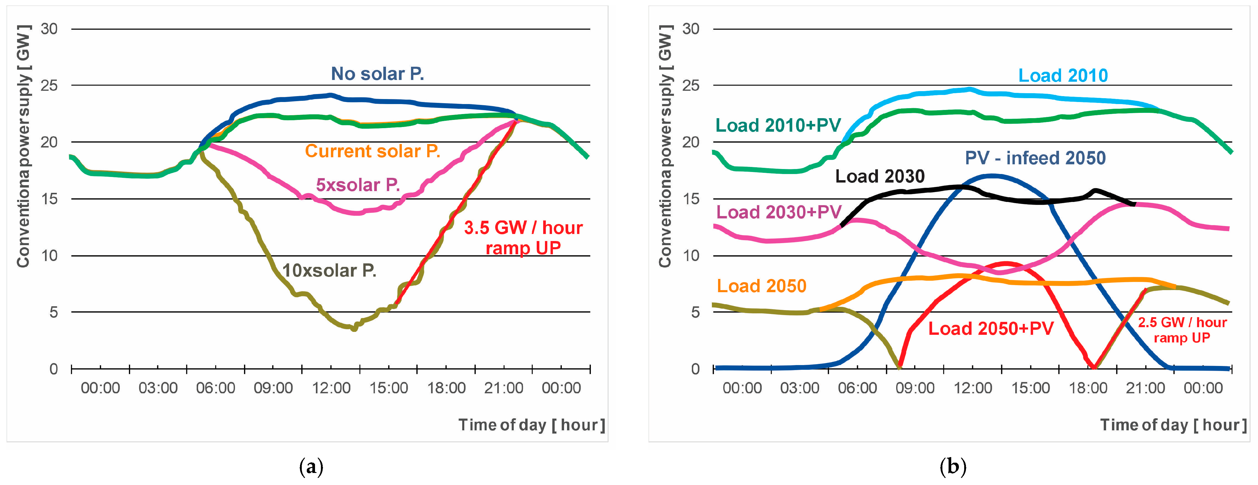
Figure 1. Electrical energy production and production forecasts for German Amprion transmission system operators (TSOs) area, in the coming years, using the example of 19 July 2010, taken from [4], when the electricity produced by photovoltaic installations was already 2 GW, with a total electricity production of 23.4 GW. The graph (a) shows an approximation based on data measured in 2010, while the graph (b) present a simulation from [5] showing the changes expected for 2030 and 2050 and data from 2010. Both graphs contain drawn ramps at the highest increase in power demand in the power grid.
Energies 17 01525 g001
Figure 3. Diagram with hydrogen production methods based on [54].
Energies 17 01525 g003
Figure 4. Hydrogen production natural sources in industrial hydrogen production—chart created by authors, based on [58].
Energies 17 01525 g004
Figure 5. Pictorial representation of hydrogen atoms permeability through the chemical structure of steel and steel hydrogen corrosion phenomena—authors’ own image.
Energies 17 01525 g005
Figure 6. The function of the density of compressed hydrogen and ideal gas with the pressure of this compression [58].
Energies 17 01525 g006
Figure 7. Graph of the mass fraction of elements C (red color) and H (blue color) in HCNG and ratio on numbers of their molecules (green), calculations based on fundamental chemical properties of hydrocarbons [159,160].
Energies 17 01525 g007
Figure 8. Chart of the HCNG density as the function of mass hydrogen content [161,162,166]. The orange line is based on these sources that give a higher value of calculated density, and the blue line is based on sources that give a lower density value.
Energies 17 01525 g008
Figure 9. Volume content of hydrogen in HCNG and mass ratio of hydrogen to methane in HCNG, based on extreme values of NG and hydrogen densities [161,162,166]. The orange line is based on these sources which give a higher value of the volumetric content of H2 in HCNG, and the blue line is based on sources that give a lower value of the volumetric content of H2 in HCNG. The light blue line represents the mass ratio of hydrogen to methane in HCNG.
Energies 17 01525 g009
Figure 10. Chart of density as the function of hydrogen mass content in HCNG0-12 (max ~50% of volumetric hydrogen content in HCNG) [161,162,166]. The orange line is based on these sources that give a higher value of calculated density, and the blue line is based on sources that give a lower density value. The legend at the top corresponds to the volume concentration of hydrogen, thus determining the “x” value for HCNGx fuel, which is based on the values calculated and shown in the previous chart, where the colors of the legend also correspond to the relevant literature sources.
Energies 17 01525 g010
Figure 11. Graphical representation of the quantum spin properties of hydrogen—authors’ graphics prepared, based on [178].
Energies 17 01525 g011
Figure 12. Low (grey) and high (blue) heating values of HCNG fuel and hydrocarbon fuels (red) as the function of hydrogen mass content in HCNG and volumetric heating values (orange [158,162], yellow [158,166]) as the function of mass content in HCNG [158,161,162,166,168].
Energies 17 01525 g012
Figure 13. Low (grey) and high (blue) heating values of HCNG fuel as the function of hydrogen mass content in HCNG [158,161,162,166,168].
Energies 17 01525 g013
Figure 14. Percentage, relative change in the mass heating values for low (grey) and high (blue) heating values, and volumetric heating values (orange [158,162], yellow [158,166]) as the function of mass content in HCNG [158,161,162,166,168].
Energies 17 01525 g014
Figure 15. Percentage change in calorific volumetric values as the function of hydrogen mass content in HCNG0-12 (max ~50% of volumetric hydrogen content in HCNG), where the green line is a pure NG fuel in HCNG [158,161,162,166,168]. The yellow and orange curves are typical Polish NG representation (red), and pure methane is CNG (yellow) [58,162].
Energies 17 01525 g015
Figure 16. High (grey) and low (orange) Wobbe index are the functions of hydrogen mass content in HCNG.
Energies 17 01525 g016
Figure 17. High values (grey) and low values (orange) of the Wobbe index as the function of hydrogen mass content in HCNG0-12 (max ~50% of volumetric hydrogen content in HCNG). They are calculated based on [158,161,162,166,168] in a combination enabling the determination of the extremes of the highest and lowest possible Wobbe index values.
Energies 17 01525 g017
Figure 18. Theoretical combustion flame temperature of HCNG as the function of hydrogen mass content in HCNG. The orange curve is from [164], and the blue curve is from [161].
Energies 17 01525 g018
Figure 19. Kappa value of pure HCNG as the function of hydrogen mass content—blue chart based on [247,248,249,250], yellow chart based on [251,252,253,254].
Energies 17 01525 g019
Figure 20. Four charts represent HCNG mixed with air in stoichiometric proportion as the function of hydrogen mass content in HCNG0-12 (max ~50% of volumetric hydrogen content in HCNG), and two of them are the same as in Figure 19—only for pure HCNG kappa value. The kappa value of pure HCNG is on the blue chart based on [247,248,249,250] and the yellow chart based on [251,252,253,254]. HCNG mixed with air represents a grey chart based on [162,247,248,249,250], an orange chart based on [162,251,252,253,254], a brown chart based on [161,251,252,253,254], and dark blue (invisible on this chart—look at Figure 21) represent HCNG-air value based on [161,247,248,249,250].
Energies 17 01525 g020
Figure 21. Kappa value of HCNG mixed with air in stoichiometric proportion as the function of hydrogen mass content in HCNG0-12 (max ~50% of volumetric hydrogen content in HCNG), where dark blue chart-based AFR value from [161,247,248,249,250], orange from [162,251,252,253,254], grey from [162,247,248,249,250], and brown from [161,251,252,253,254].
Energies 17 01525 g021
Figure 22. Heat release rate (HRR) value as the function of crankshaft angle degrees (CAD) for CNG and different HCNG fuels [295].
Energies 17 01525 g022
Figure 23. Theoretical, CO2 emission is calculated for a 100% efficiency combustion process as the function of hydrogen mass content in HCNG, calculations based on [158] fuel parameters.
Energies 17 01525 g023
Figure 24. The theoretical CO2 emission for different types of engines and fuel replacement level for DF engines is calculated as the function of hydrogen mass content in HCNG—calculations based on [104,158,161,268,317,318,319,320,321,322,323,324,325] sources.
Energies 17 01525 g024
Figure 25. A famous graphic from Wikipedia showing HCNG advantages, [330] shows toxic components of exhaust gas combustion from CNG and hythane gases.
Energies 17 01525 g025
Table 1. WTW CO2 emissions (g/MJ) for HCNG are produced through different routes and with different hydrogen content [28] and hydrogen production costs [29,30,31,32,33,34,35,36].
H2 content[%]100%8%20%25%30%
Electrolysis green electricity66USD 3–6/kg [29,30,32]64626059
CO2 change[%]-−2.4%−6.4%−8.3%−10%
Electrolysis EU-mix electricity66USD 4–6/kg or EUR 12/kg [33]70778084
CO2 change[%]-+6.1%+17%+22%+27%
Reforming natural gas66USD 0.5–2/kg [34,35,36]68727476
CO2 change[%]-+3.5%+9.7%+13%+16%
Table 2. Basic properties of hydrogen and natural gas, with information about the literature sources [28,102,103,104,105,106].
Natural GasHydrogenSource
Hydrogen to carbon ratio4:1-[161]
Energy density [MJ/kg]48–50120[161]
49.15119.9[158]
50.02119.93[58]
Energy density [MJ/dm3]12.63.0[162]
Auto   ignition   temperature   [ K ]903793[163]
813858[161]
810858[157,164,165]
Minimum   ignition   Energy   [ m J ]0.290.02[161]
0.2740.017[163,164]
Minimum   spark   ignition   ( SI )   Energy   [ m J ]0.290.02[162]
Octane rating120+130+[161]
Octane numberRON 120-[162]
Flammability limits [%]5.3–15%4–75%[163]
5.3–14%4–70%[161]
5.3–17%4–70%[164]
Stoichiometric Air/fuel ratio9.4829.53[162]
Stoichiometric   F / A   [ k g f u e l / k g a i r ]0.0580.029[161]
Wobbe   Index ,   M J / N m 3 47.91–53.2840.65–48.23[161]
Flame velocity in the air at NTP [cm/s]37–45265–325[161]
38.5315[164]
Flame temperature [K]21482318[161,163]
22302396[164]
Density   [ g / L ]0.70.07[161]
0.6570.8988[166]
-0.08375[167]
0.6680.084[164]
Density   ( gaseous )   [ k g / m 3 ]0.7160.09[162]
Mainly emissions H C , C O , C O 2 , N O 2 , C H 4 H 2 O , N O x [161]
Energy Density [MJ/Lts]25.32.9 at 350 bars[161]
Molecular   weight   [ k g / k m o l ]16.0432.016[162]
Lower   heating   value   [ M J / k g ]50120[162]
Higher heating value50.02141.86
55.9142.2[168]
Laminar   flame   speed   [ c m / s ]≈42≈230[162]
Lower explosive limit [%]6.318.3[164]
Higher explosive limit [%]13.559[164]
Table 3. Chosen physical and thermodynamic properties of different quantum forms of hydrogen [3].
PropertiesHydrogen
Para-Hydrogen75% of Ortho- + 25% of Para-H2
Density in 0 °C, 103 mol/cm30.05460.0446
Cp in 0 °C, J/(molxK)30.3528.59
Cv in 0 °C, J/(molxK)21.8720.3
Enthalpy in 0 °C, J/mol7656.67749.2
Internal energy in 0 °C, J/mol5384.55477.1
Entropy in 0 °C, J/(molxK)127.77139.59
Thermal conductivity in 0 °C, mW/(cmxK)1.8411.74
Table 4. The content of para-hydrogen in molecular hydrogen depends on its temperature [174].
Temperature [K]20.39304070120200250300
Para-hydrogen in hydrogen in %99.8097.0288.7355.8832.9625.9725.2625.07
Table 5. Physical properties related to fire and explosion hazards with information about explosive properties of natural gas and hydrogen [164,228,229,230,231,232,233,234]. The base source is [164].
Natural GasMethaneHydrogenHCNG50
Lower flammability volumetric limit [%]5.3/4.4 [234]5 [230]4~5
Higher flammability volumetric limit [%]1714.3 [230]75~24
Lower explosive volumetric limit [%]6.35 [233]18.3~7
Higher explosive volumetric limit [%]13.515 [233]59~20
Maximal flame speed [m/s]0.374 [231]0.3853.15/2.933 [231]~0.68
Minimal ignition energy [mJ]0.31 [229]0.2740.017~0.27
Self-ignition temperature [°C]582 [232]537/540 [228]585~583
Table 6. The theoretical efficiency of ICEs as a function of compression ratio (CR) compared with the kappa value of pure air, CNG mixed with air, and HCNG50 mixed with air and the proportional percentage difference between CNG and HCNG theoretical ICE efficiency—“AIR” efficiency is a reference for comparison for SI engine (left side of the table) and CI (right side of the table) [285].
CRAIRCNGHCNGDiff.:CRAIRCNGHCNGDiff.:
651.1%51.0%51.1%−0.31%1672.2%72.0%72.2%−0.25%
754.1%53.9%54.1%−0.30%1773.0%72.8%73.0%−0.25%
856.4%56.3%56.5%−0.29%1873.8%73.6%73.8%−0.24%
958.5%58.3%58.5%−0.28%1974.5%74.3%74.5%−0.24%
1060.2%60.0%60.2%−0.28%2075.2%75.0%75.2%−0.24%
1161.7%61.5%61.7%−0.27%2175.8%75.6%75.8%−0.23%
1263.0%62.8%63.0%−0.27%2276.4%76.2%76.4%−0.23%
1364.1%64.0%64.1%−0.26%2377.0%76.8%77.0%−0.23%
1465.2%65.0%65.2%−0.26%2477.5%77.3%77.5%−0.23%
Average difference:−0.28%Average difference:−0.24%
Disclaimer/Publisher’s Note: The statements, opinions and data contained in all publications are solely those of the individual author(s) and contributor(s) and not of MDPI and/or the editor(s). MDPI and/or the editor(s) disclaim responsibility for any injury to people or property resulting from any ideas, methods, instructions or products referred to in the content.