Review

A Comprehensive Review of the Thermohydraulic Improvement Potentials in Solar Air Heaters through an Energy and Exergy Analysis

by
Ali Hassan
1,
Ali M. Nikbakht
1,
Sabrina Fawzia
1,
Prasad Yarlagadda
2 and
Azharul Karim
1,*
1
School of Mechanical, Medical and Process Engineering, Queensland University of Technology, Brisbane 4000, Australia
2
School of Engineering, University of Southern Queensland, Springfield 4300, Australia
*
Author to whom correspondence should be addressed.
Energies 2024, 17(7), 1526; https://doi.org/10.3390/en17071526
Submission received: 31 December 2023 / Revised: 5 March 2024 / Accepted: 14 March 2024 / Published: 22 March 2024
(This article belongs to the Section A2: Solar Energy and Photovoltaic Systems)

Abstract

:
Supply disruptions, uncertainty, and unprecedented price rises of fossil fuels due to the recent pandemic and war have highlighted the importance of using renewable sources to meet energy demands. Solar air collectors (SACs) are major types of solar energy systems that can be utilized for space and water heating, drying, and thermal energy storage. Although there is sufficient documentation on the thermal analyses of SACs, no comprehensive reviews of the exergetic performance or qualitative insight on heat conversion are available. The primary objective of this article is to provide a comprehensive review on the optimum conditions at which the thermal performance of diverse types of solar air collectors is optimized. The effect of operating parameters such as temperature rise, flow rate, geometric parameters, solar radiation, and the Reynolds number on the thermal performance of SACs in terms of thermal hydraulic performance, energy, and exergy efficiencies has been reviewed adaptively. Beyond the operating parameters, a deep investigation is outlined to monitor fluid dynamics using analytical and computational fluid dynamics (CFDs) methodologies in the technology of SACs. In the third phase, thermodynamic irreversibility due to optical losses, thermal losses between absorber and environment, heat losses due to insulation, edge losses, and entropy generation are reported and discussed, which serve as the fundamental tools for optimization purposes.

1. Introduction

The generation of electricity, transport, refrigeration, and many other applications emit harmful greenhouse gases into the atmosphere. These greenhouse gases cause a rapid negative change in the climate, which results in global warming. Global warming causes polar ice to melt and forest fires to occur, which ultimately affect wildlife and aquatic life throughout the world. Water temperature changes caused by global warming may alter the physiology and metabolism of aquatic life, affecting the abundance, behavior, growth, and migration of fish and other aquatic animals [1]. In 2019–2020, Australia experienced the unprecedented black summer bushfire due to climate change, which not only caused a large volume of loss of wildlife but also caused human life and economic losses [2]. Moreover, recent supply chain disruptions and unprecedented price fluctuations of fossil fuels due to the COVID-19 pandemic and war have created serious nervousness among countries about future energy security. Therefore, the world is accelerating its shift toward renewable and net-zero carbon emission resources. Australia has set a target of achieving net-zero carbon emissions along with China, Japan, and South Korea by the end of the year 2050 [3]. Many countries have already outlined their plans to move to 100% electric cars in the next 10–20 years.
Renewable energy resources, including solar, wind, geothermal, hydropower, and biomass, are perfect replacements for fossil fuels for power generation, with the benefit of emitting almost zero net carbon emissions. Among the alternative resources, solar energy is available in abundance in all countries. The earth receives 174 × 1015 W of radiation [4]. It has been estimated that 1% of solar energy would create more than 10 times the world’s energy demand [5]. Solar energy can be utilized either for direct power generation using photovoltaics or for indirect power generation and heating applications using solar collectors. Enhancing the performance of either system (photovoltaics or solar thermal collectors) has been a challenging issue in the last decade. The use of solar energy in a hybrid solar fuel system can effectively minimize pollutants and increase the efficient utilization of solar energy [6]. The electrical efficiency of photovoltaic–thermal hybrid systems has been improved a lot by applying different heat transfer fluids (nanofluid, thermal oils, and water) and phase-changing materials (PCMs). It has been reported that electrical and thermal energy and exergy efficiencies are enhanced by 23.9%, 17.5%, 13.02%, and 1.78% using nanofluid–PCM combinations, respectively [7,8,9]. The outputs of solar systems, such as the electrical outputs of PVs, can be maximized by applying forecasting techniques and employing artificial intelligence such as the artificial neural network (ANN) [10].
Depending on the heat transfer fluid, solar collectors are classified as solar liquid collectors (SLCs) and solar air collectors (SACs) [11]. SACs are important for low- to medium-temperature (30–80 °C) applications such as space heating, drying applications, and thermal energy storage [12,13]. SACs have more benefits than solar liquid collectors (SLCs) due to the lower manufacturing costs, direct application of heat without the requirements of an additional heat exchanger, and ease of handling [14]. However, SACs suffer from low thermal performance compared to SLCs due to the low heat transfer properties between the absorber plate and air [15]. Attempts have been made to optimize SAC performance using selective coating, different absorber shapes, airflow channel geometry, and varying the inlet temperature and mass flow rate. Close [14] compared three designs of solar air collectors based on the flow channel (over, under, and on the side of the absorber), and their results showed that the absorber with flow over the plate might exhibit better performance. Alta and Bilgili [15] showed that double glass with a fin absorber had better thermal performance than single glass. Stanciu and Stanciu [16] developed a theoretical model for flat-plate SAC for optimum tilt angles at different geographical locations to achieve a higher useful energy gain, which was later verified by Maia, Ferreira, and Hanriot [17].
Research on enhancing the surface area of the absorber is a key focus of research, as thermal performance is mainly dependent on the absorber shape/area. V-groove absorbers, absorbers with fins, absorbers with baffles, absorbers with roughness, jet impingement absorbers, and a combination of these absorbers and wire mesh absorbers are the prime focus of research concerning enhancing performance parameters.
Thermal performance is often based on the first law of thermodynamics, which is usually sufficient for most solar collectors. However, the disadvantage of the first law is that it does not consider the degradation of energy quality, which happens during the conversion of energy from one form to another. Such a deficiency needs to be evaluated in order to overcome the irreversibility generated within the system, which can be explained using the second law of thermodynamics, known as exergy analysis [18]. Exergy represents the maximum available work in a system during a process. It quantifies the potential of a system to work, counting entropy and energy, respectively. Unlike energy, exergy is destroyed during the real process because of irreversibility, showing the inefficiencies in the system [19]. In solar air heaters, exergy analysis is crucial due to their technological variations in terms of the absorber design and operating parameters, because exergy efficiency is an index that does not ignore the boundary conditions and special properties of each process. The exergy in solar air heaters has been explained in detail in Section 3.
Beyond deep insights on the effects of absorber designs and corresponding thermo-physical properties, this review provides, for the first time, an adaptive discussion on the second law of thermodynamics in terms of exergy efficiency, exergy loss, sustainability index, and improvement potential to make a qualitative comparison in the SAH industry. It highlights the significance of exergetic measures for researchers in the field. Moreover, discussions on mathematical formulations on the effects of geometric parameters on collector performance criteria and fluid dynamics are appended for better explanations of the flow behavior within collectors. Although there exist numerous empirical models on the nature of thermal hydraulic parameters in solar collectors, there is no documentation on the dimensionless comparisons within the wide range of designs introduced in the literature.

2. Global Energy Trend

There has been a huge push to increase the share of renewables in energy demand worldwide. Figure 1 shows a comparison of renewable energy generation among different continents. It can be seen that Europe is the pioneer in solar energy generation, followed by Central South America. However, the actual share of renewable energy in relation to the total energy demand for each continent is very small. Europe has only 4.6% renewable energy share in its total energy economy, which is still dominated by the energy generated by oil (31%).
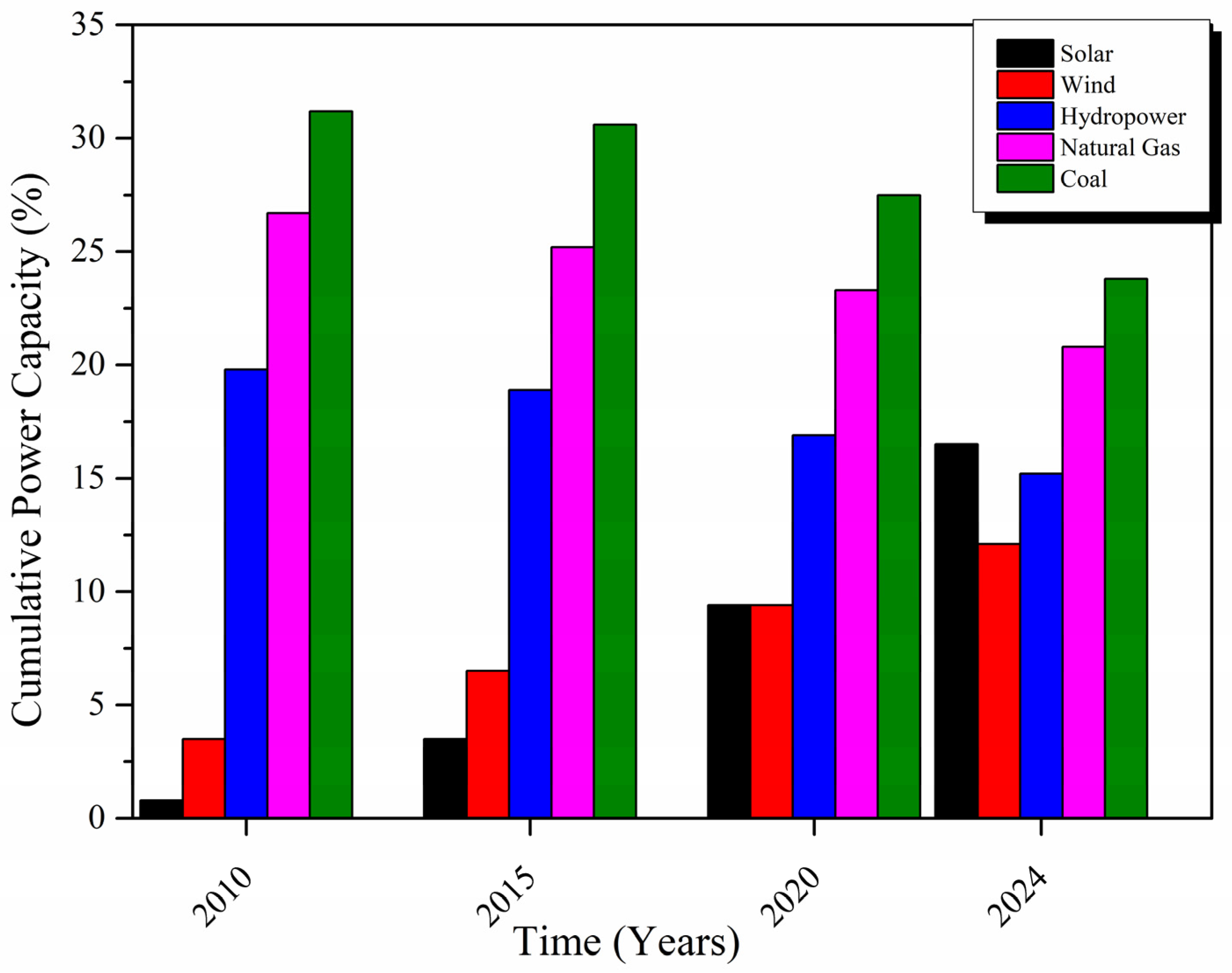
Figure 2 presents the global sources of energy generation over the years. Solar energy has been increasing linearly, gaining interests from local to international energy corporations. The trend not only highlights the growing prioritization and awareness of renewable energy, especially solar energy, but it also signals a positive step toward reducing the dependency on fossil fuels.

3. Classification of Solar Air Collectors

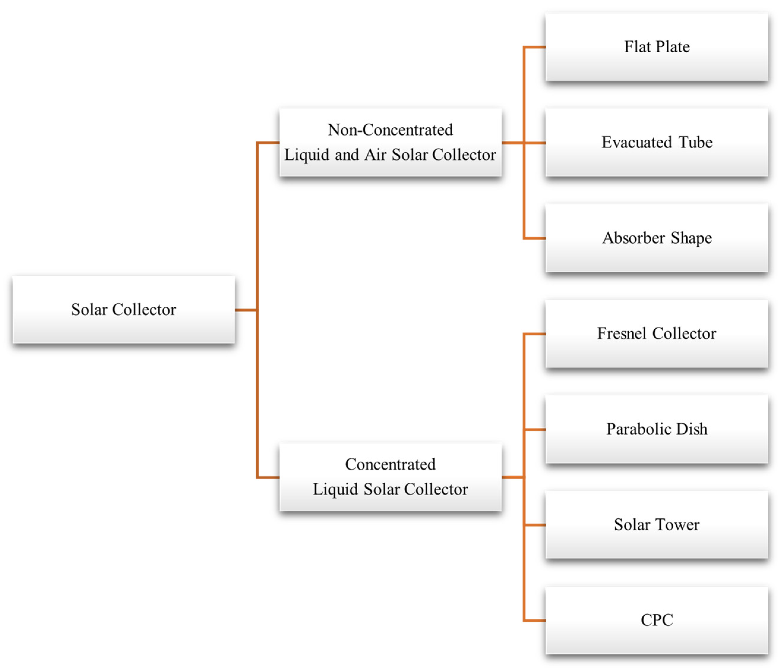
Solar collectors are primarily categorized into two types: concentrated and non-concentrated collectors, as shown in Figure 3. Concentrated solar collectors are outside the scope of this paper. Non-concentrated collectors are further categorized into flat-plate, evacuated tube, and other absorber shapes.
The energy gained by the working fluid can be utilized for water and space heating, drying applications, and thermal energy storage [21]. The net energy absorbed by the working fluid can be improved by determining the optimum value of the operating parameters. Wahab et al. [22] reviewed the parameters that effect the thermal performance of solar collectors as a graphical illustration. Ali et al. [23] adopted a similar approach of evaluating the parametric analyses of different studies to analyze PV performance. A similar approach has been adopted in this review study to evaluate the solar air heater performance based on different parameters. Figure 4 shows the various parameters affecting the thermal performance of the solar air heater. Each of the parameters has been discussed below.

3.1. Effect of Flow Rate

The mass flow rate of air has a significant effect on the thermal efficiency and outlet air temperature of SACs. Generally, the thermal efficiency of SACs is enhanced in increments in the mass flow rate up to an optimum value [24,25,26]. The thermal efficiency of SACs can be calculated using Equation (1).
η = Q u I A c  
Q u is calculated using Equation (2):
Q u = m ˙ C p T o u t T i n
where Q u is the useful heat gain (J/s), I is the solar radiation (W/m2), and A c is the collector area (m2), C p is the specific heat constant (J/kgK) and T o u t and T i n are the outlet and inlet air temperature (K).
Figure 5 represents the effect of the flow rate on the thermal efficiency of solar air collectors. The rate of increments in thermal efficiency is high at lower mass flow rates because the exit temperature of air has a dominant effect as air has a greater chance to absorb heat, causing increments in the air temperature. At higher mass flow rates, the temperature effect of air is mitigated due to the low resident time in the solar air collector; on the other hand, more air is allowed to pass through the collector, which helps to enhance the heat transfer between the absorber and air, resulting in a rise in the thermal efficiency of solar air collectors [27,28,29].
Along with the positive effects of the flow rate on thermal efficiency, it helps to reduce the time constant (the time required for a system to achieve a steady state) at high flow rates, e.g., 300 s, 310 s, and 370 s for 182, 140, and 100 m3/hr, respectively [32].
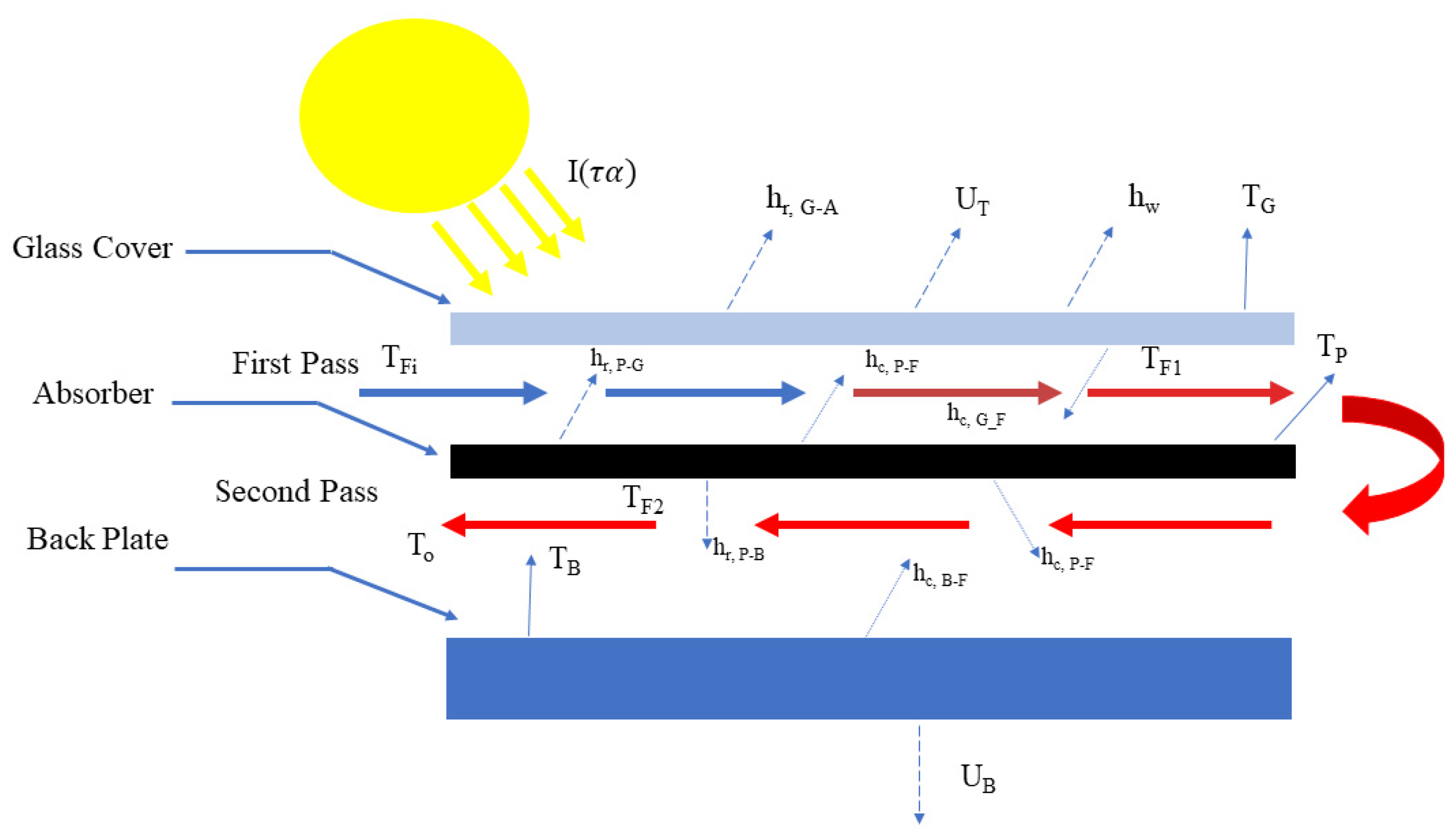
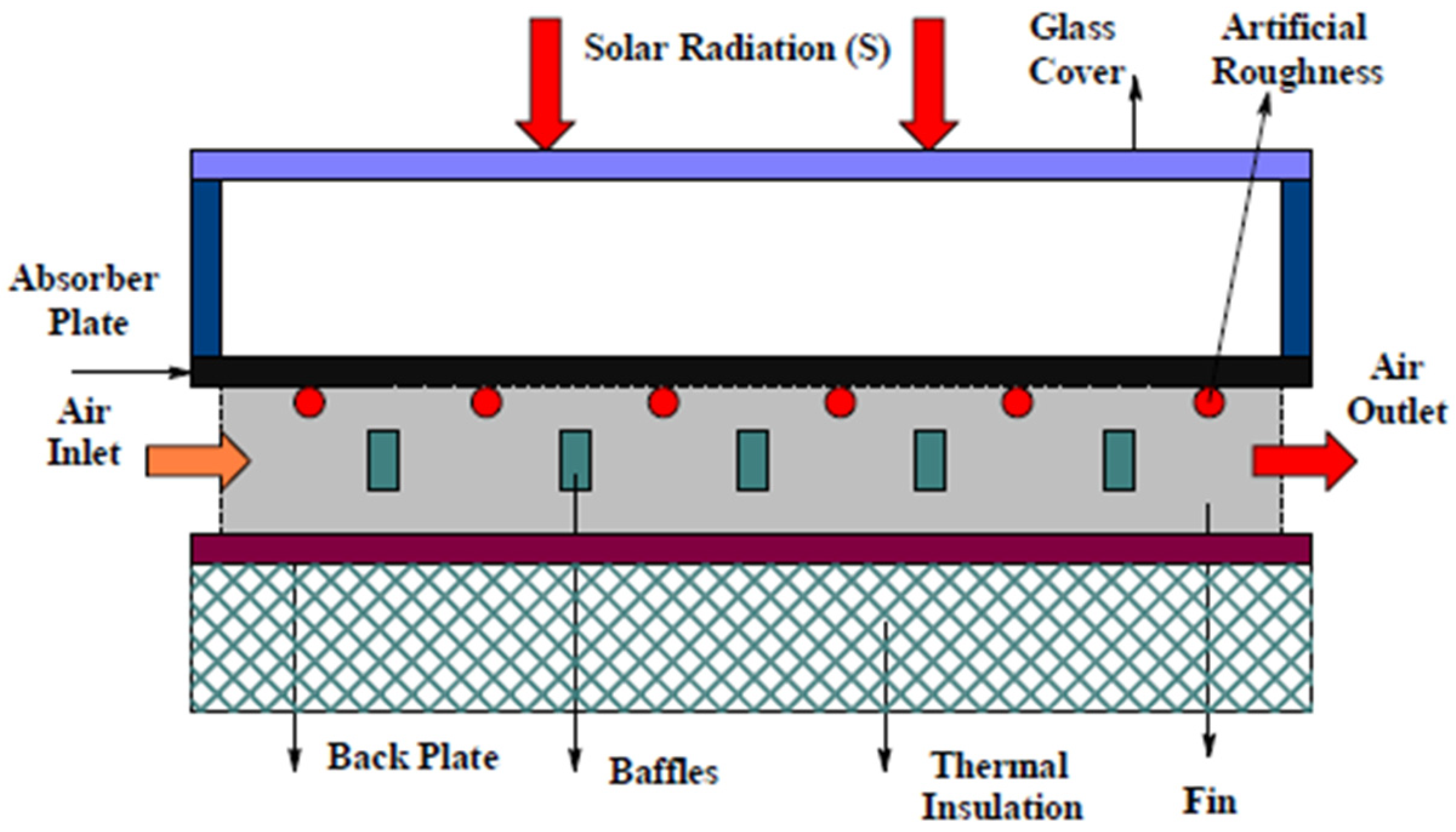
The thermal performance of solar air heaters can be determined by developing a mathematical model. A large number of models have been developed in the literature, depending on the type of collector. Hassan et al. [33] developed and validated a mathematical model for V-groove double-pass solar air heaters. The model was solved in MATLAB. The system was assumed to be a steady state and one-dimensional flow. Energy balance equations for the glass cover, absorber plate, back plate, and air flow were developed based on the heat transfer network, as shown in Figure 6.
α G I + T F 1 T G h c , G F + T p T g h r , P G = U T T P T A
h r , P G T P T G + h c , P F T P T F 1 + h r , P B T P T B + h c , P F T P T F 2 = α P τ G I
Q 1 + h c , G F T F 1 T G = h c , P F T P T F 1
Q 2 + h c , B F T F 2 T B = h c , P F T P T F 2
U B T B T A = h c , B F T F 2 T B + h r , P B T P T B
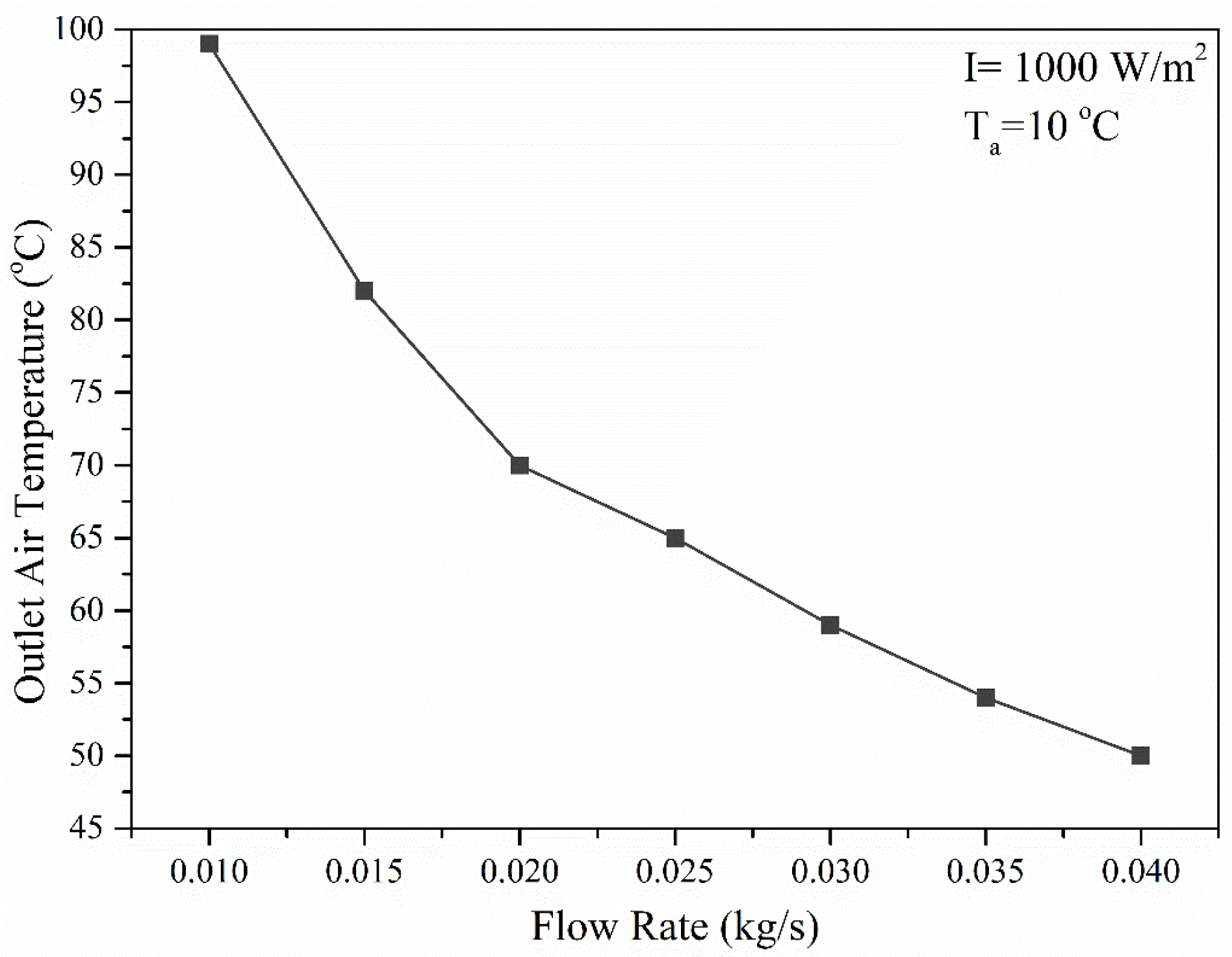
In terms of the outlet air temperature, mass flow has an inverse relationship with the outlet air temperature. Figure 7 presents the effect of the flow rate on the outlet air temperature. The higher the mass flow rate, the lower the outlet air temperature. At low mass flow rates, air has more time to absorb heat, resulting in a higher outlet air temperature. With an increase in the flow rate, the residency time of air decreases, which reduces the outlet air temperature.
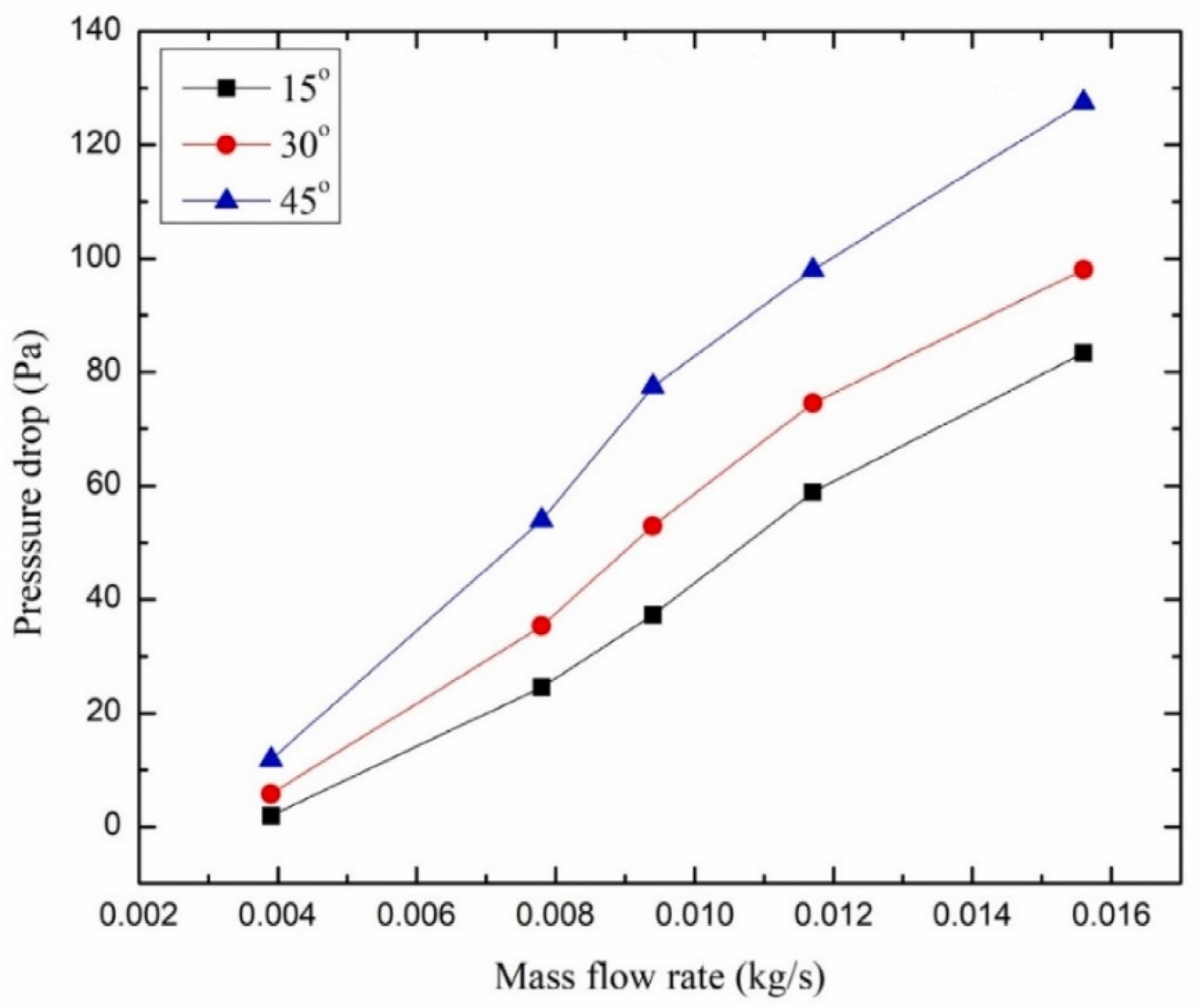
The main drawback of increasing the flow rate is the requirement for increased pumping power. The pressure drop in the collector increases with increments in the mass flow rate. An increase in the mass flow rate allows for more air to pass through the collector along the axial direction, causing the higher pressure to drop with increments in pumping power [25,27,34]. The inclination angle of the solar air collector also affects the pressure drop [35]. Figure 8 represents the effect of the inclination angle and mass flow rate on the pressure drop. The increase in the inclination angle causes the air to overcome the gravitational effect, resulting in an enhanced pressure drop [36].
The thermal hydraulic efficiency, or effective efficiency, is an indication of the thermal efficiency of solar air collectors, including the pumping power required. This is described as follows:
η T H = Q u P f a n A p I  
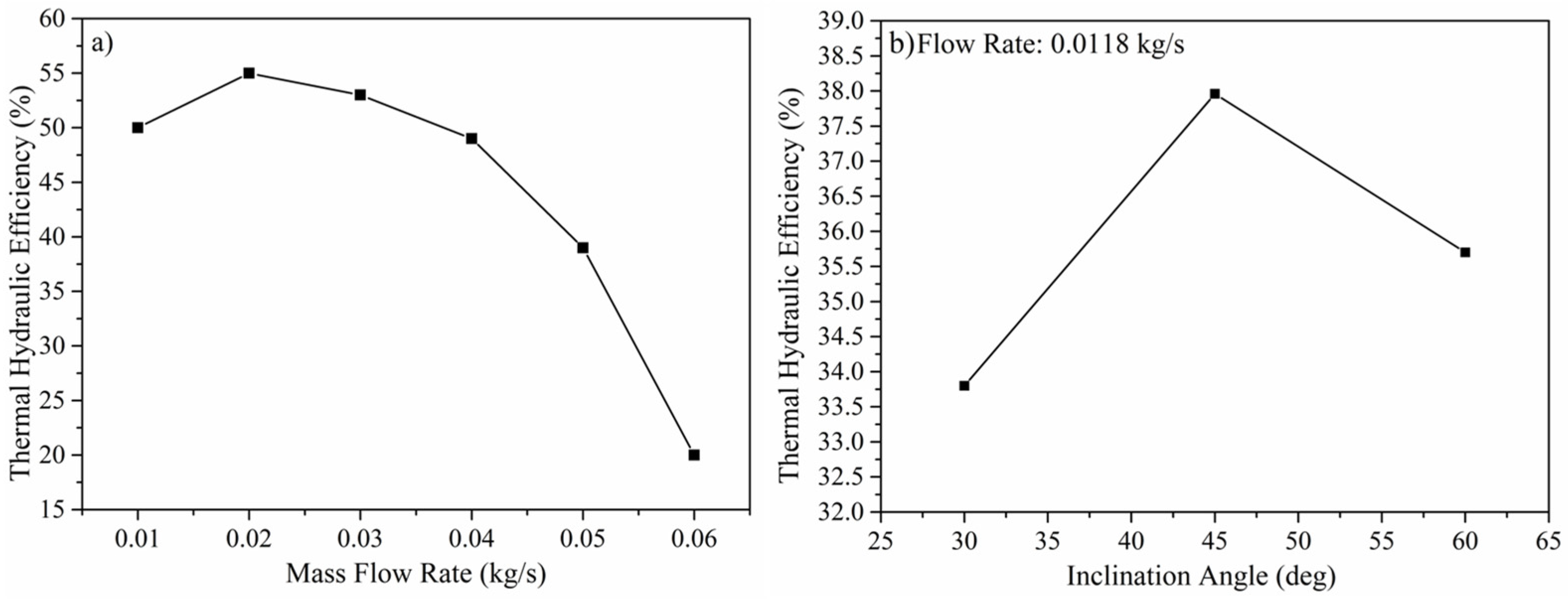
where P f a n represents the power of the fan in Watt. The thermal hydraulic efficiency increases with an increase in the mass flow rate up to an optimum value of the flow rate, as shown in Figure 9. Further increases in the mass flow rate resulted in reduced thermal hydraulic efficiency because increasing the mass flow rate caused an increase in the pumping power of the fan, which reduced the thermal hydraulic efficiency of the system [37]. Another factor that affects the thermal hydraulic efficiency is the inclination angle. Debnath et al. [36] found that thermal hydraulic efficiency started to decrease with increments in the inclination angle above the optimum point.
Pfister, Ralston, and Kim [34] designed a triangular-shaped absorber made from six black aluminum grids. The results showed that conductive and convective heat losses were minimized at higher mass flow rates.

3.2. Effect of Temperature Rise Parameters

The temperature rise parameter is defined as follows:
T R P = T o T a I
The thermal efficiency decreases with increments in the temperature rise parameters [38,39]. Figure 10 represents the temperature rise parameter effect on thermal efficiency [40,41,42,43]. A high temperature rise parameter means either low solar irradiance or high outlet air temperatures. Thermal efficiency is highly dependent on solar radiation. More energy is available to solar air collectors at higher solar radiations, which can later be converted to useful heat by the air passing through the collector, resulting in higher thermal efficiency of the system.
Akpinar et al. [41] used triangular, leaf-shaped, and rectangular obstacles on an absorber plate to compare their thermal performance with a flat-plate collector. Leaf-shaped obstacles outperformed triangular and rectangular obstacles in terms of thermal and exergy efficiency because of the high heat transfer rate between the air and absorber due to a high turbulence effect. It can be seen that the performance of the solar air collector highly depends on the design of the absorber.

3.3. Effect of the Flow Rate and Re Number on Nusselt Number

The Nusselt number is defined as the ratio of convective to conductive heat transfer.
N u = h D h k  
where h , D h , and k are the convective heat transfer coefficient, hydraulic diameter, and thermal conductivity of the fluid. Generally, the Nusselt number is evaluated using the Dittus–Boelter equation, defined as follows:
N u = 0.024 R e 0.8 P r 0.4
where R e is the Reynold number and P r   is the Prandtl number.
The Nusselt number is affected by the flow rate and geometry of the system. Figure 11 shows that the Nusselt number increases with an increasing flow rate and the Reynold number. This is due to the fact that the transition of flow behavior moves from laminar to turbulent, resulting in the dominance of convective heat transfer over conductive heat transfer.

3.4. Effect of Reynold Number on Friction Factor

The friction factor is one of the reasons for increased pumping power in a solar air heater, which can be evaluated using the following equation:
f r = 2 P d D h 4 ρ L d V 2  
where P d is the pressure drop, ρ is the density of air, L d is the length of duct, and V 2 is the velocity of air.
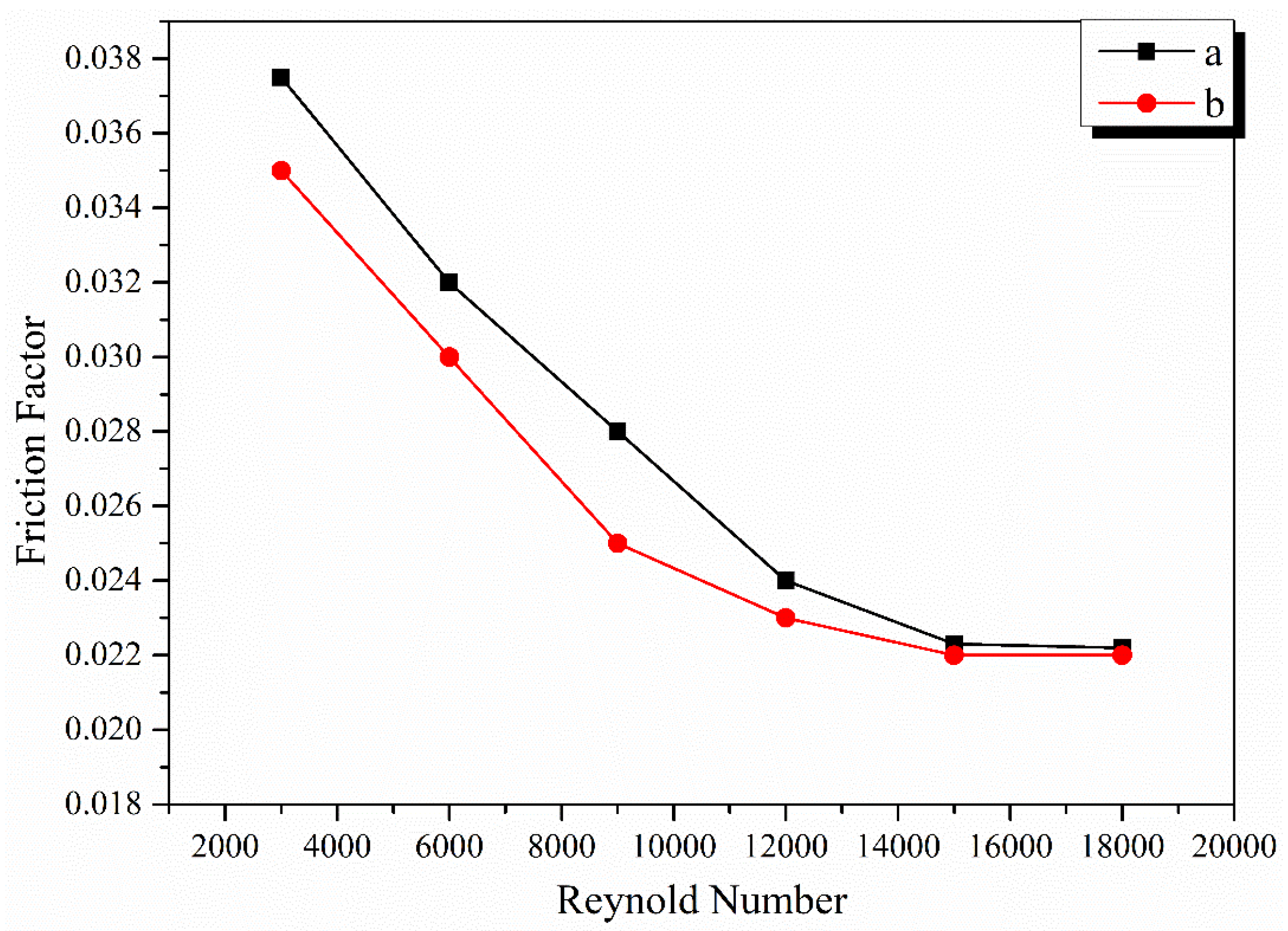
Figure 12 shows that the friction factor decreases with increments in the Reynold number. This is because the flow transition from laminar to turbulent suppresses the laminar sublayer and provides better flow mixing, reducing any sublayer formation with the surface. The Blasius equation is used to evaluate the friction factor in terms of the Reynold number [47]:
f r = 0.079 R e 0.25

3.5. Impact of Geometry/Shape of SACs

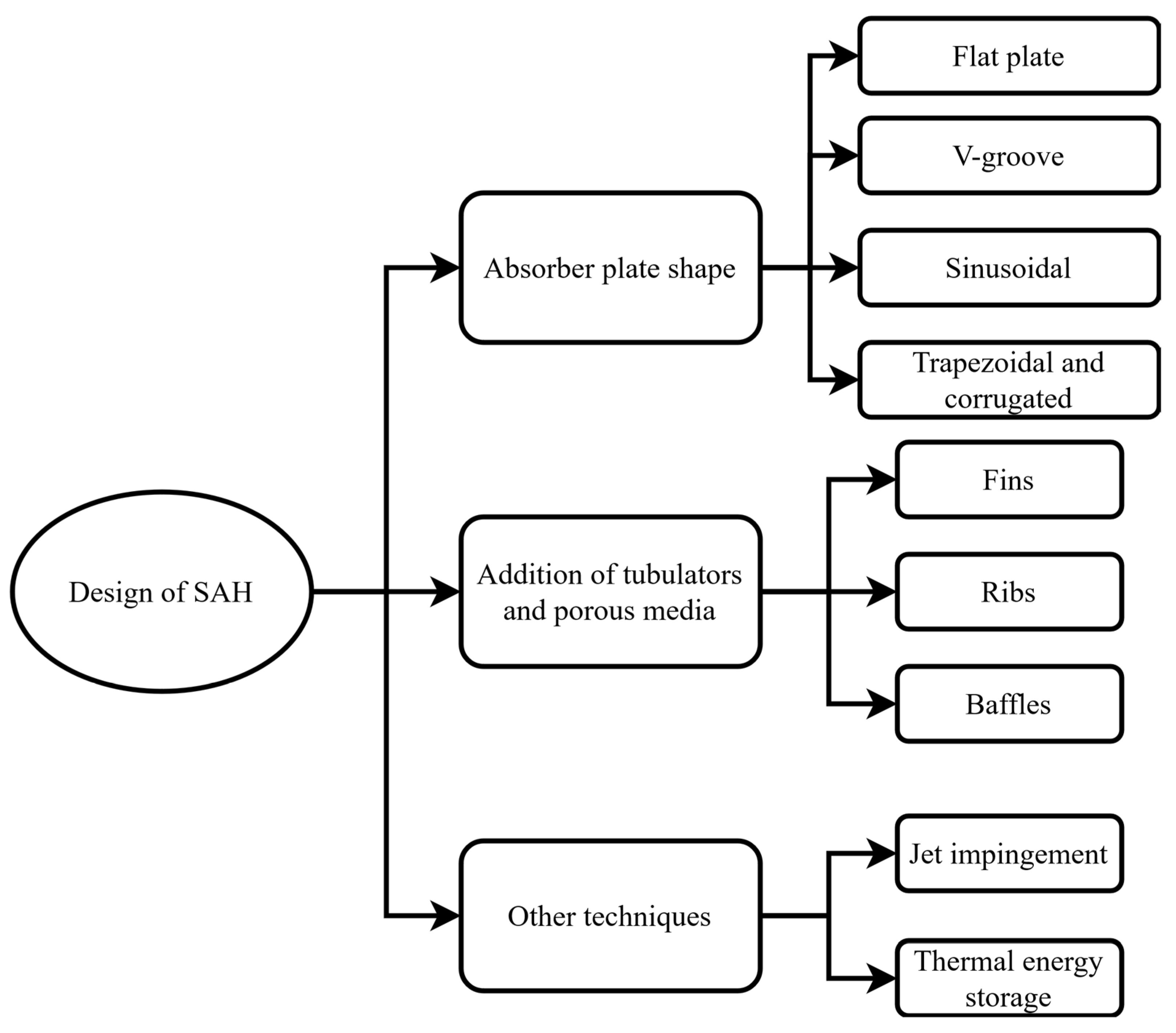
An alternative approach for enhancing the thermal performance is to either elevate the fluid heat transfer properties or enhance the heat transfer area by upgrading the design parameters of the absorber. In the case of air, the former option is not applicable, and therefore the only scenario is to modify the absorber design and geometry. Figure 13 presents different designs of the absorber to enhance the thermal output from the solar air heater.

3.6. Absorber with Fins/Ribs

The addition of fins to the absorber surface provides an advantage for the enhanced heat transfer surface area and reduces the dead zones (where there is no heat transfer) due to the generation of the turbulence effect [50]. The designs of fins/ribs in terms of shape, spacing, height, and pitch are important parameters for optimizing the performance of the solar air heater. The design factors that impact thermal performance are described below.

3.6.1. Fin/Ribs Spacing

Hachemi [51] studied the staggered fin air collector, which generates a fully developed turbulent flow. It was found that the thermal performance increased by reducing the gap between two consecutive rows of fins. The thermal efficiency increased from 38.6% to 75.5% using fins with a fin length of 10 cm, and the space between two consecutive staggered rows was 2.5 cm. Similar results were found by [52,53,54] that the thermal performance was enhanced by decreasing fin spacing. Bahrehmand and Ameri [55] found that tin metal sheet (TMS) with fins had higher energy and exergy efficiency at a low channel depth compared to collector with fins and without TMS. In another study, Mahmood, Aldabbagh, and Egelioglu [27] found that the thermal performance (steel wire mesh integrated with fins SAH) was reduced by increasing the air height because the air velocity decreased with an increase in height, resulting in a reduced heat transfer coefficient. The thermal efficiency and outlet temperature were enhanced by increasing the number of fins [30,56]. Wang and Liu [57] also suggested a smaller air duct height for high thermal performance using S-shaped ribs (illustrated in Figure 14). The results showed that the Nusselt number was enhanced by raising the relative rib gap width up to an optimum value. Increasing the relative rib spacing also had a positive impact on the Nusselt number. The temperature difference and efficiency were raised by enhancing the gap between the ribs and the width of the ribs, respectively.
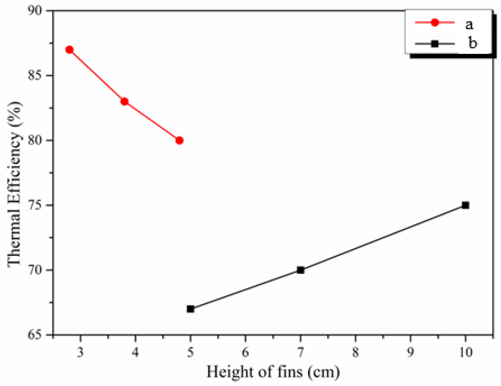
The thermal efficiency and outlet air temperature of the solar collector were raised by enhancing the height of the fins [30,58,59]. The results of these studies are in contradiction with the results from [54,60], which showed that thermal performance was reduced by increasing the fin height, as shown in Figure 15.
Rahmani et al. [61] found an increase of 50% in the Nusselt number by increasing the sinusoidal fin height by 0.5 times the duct height. Similar results were found for wavy fins by Saboohi et al. [62]. In the case of the relative height ratio (e/D), it was found that the Nu number and friction factor were raised by enhancing the relative rib height (e/D) for rectangular ribs, conical ribs, and equilateral triangular ribs, up to an optimum value of e/D [44,45,46]. Alam et al. [44] found 0.0298 to be the optimum e/D value for the Nu number and friction factor. Empirical correlations for the Nu number and friction factor were developed, which showed that the Nu number friction factor was influenced by the geometric parameters (relative rib height e/D and relative pitch ratio p/e), as shown in Equations (14) and (15), for a Reynolds number from 4000 to 16,000.
N u = 2.29 × 10 4 R e 0.984 e D 0.280 p e 4.085 e x p 0.922 ln p e 2
f = 2.19 × 10 4 R e 0.352 e D 5.839 exp 0.739 ln e D 2 p e 1.860 × exp 0.532 ln p e 2
Thermal performance parameters such as the Nusselt number, thermal efficiency, and temperature difference were enhanced by enhancing W/w, the angle of attack, and the twist ratio up to an optimum value of 85, 60°, and 3, respectively [63,64,65]. Also, it was found that non-uniform ribs had better thermal performance than uniform ribs [63]. The optimum geometric values such as relative pitch ratio, relative width, relative height, angle of attack, and twist ratio were found to vary; this was due to the different dimensions assumed for the solar air heaters.

3.6.2. Relative Pitch Ratio

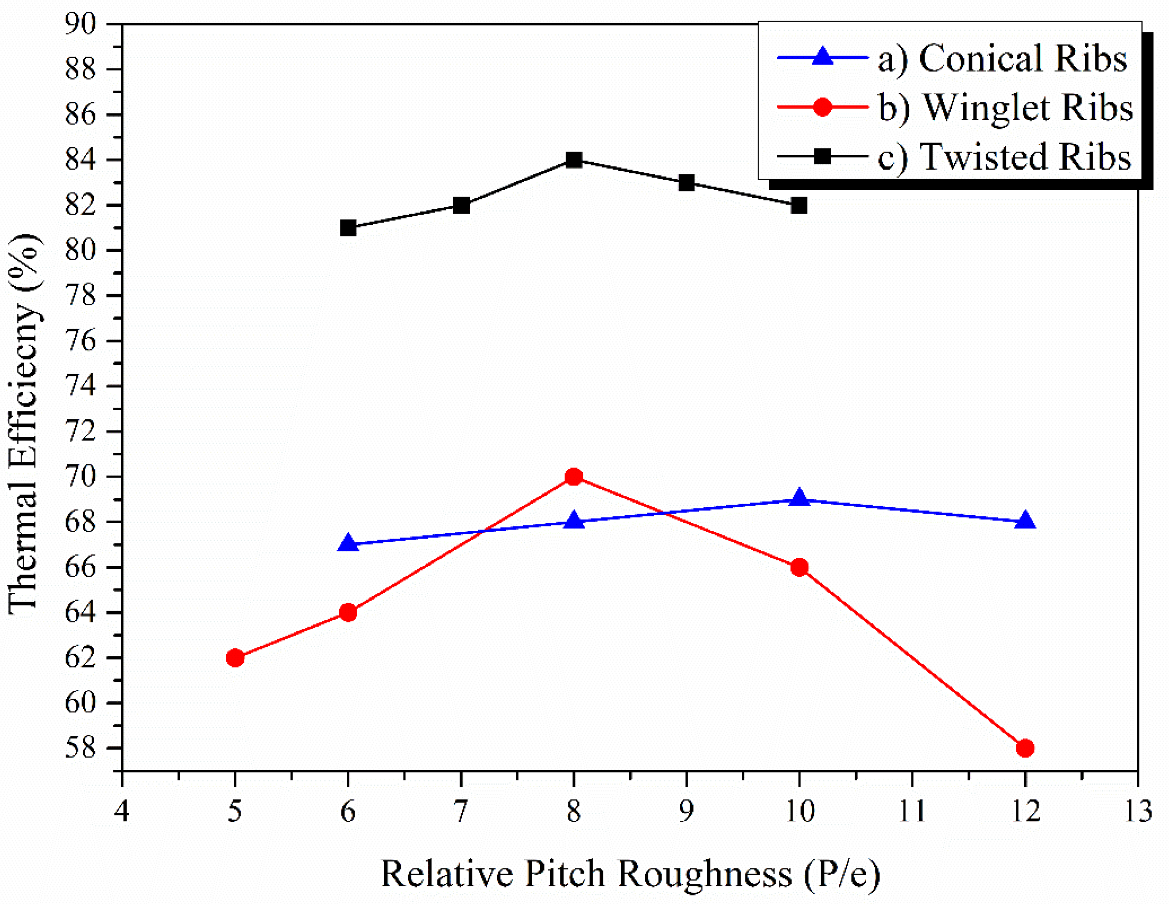
Figure 16 shows a relative pitch roughness (p/e) effect on the thermal efficiency of SACs. p/e had a positive impact on the thermal performance of SACs up to an optimum point because increasing p/e helps enhance the turbulence effect due to robust mixing, which helps reattach free shear layers near the fins/ribs and ultimately increases the heat transfer between the air and the absorber, while increasing the p/e value after the optimum point caused a decrease in the reattachment point per unit length. Because of this, heat transfer is reduced, impacting the thermal efficiency of the system. The optimum value achieved was 8 for winglets and twisted ribs and 10 for conical ribs, respectively. The twisted ribs have higher thermal efficiency compared to conical and winglet ribs. The twisted ribs offer a higher-induced turbulent effect, assisting in a higher heat transfer between the absorber plate and air. Moreover, the twisted design enables the ribs to interact with the air flow at an optimal angle, maximizing the heat transfer rate. The continuous change in the shape of twisted ribs changes the angle of attack of the ribs relative to the airflow, which can be more effective than the fixed angle presented by the winglet and conical shapes.
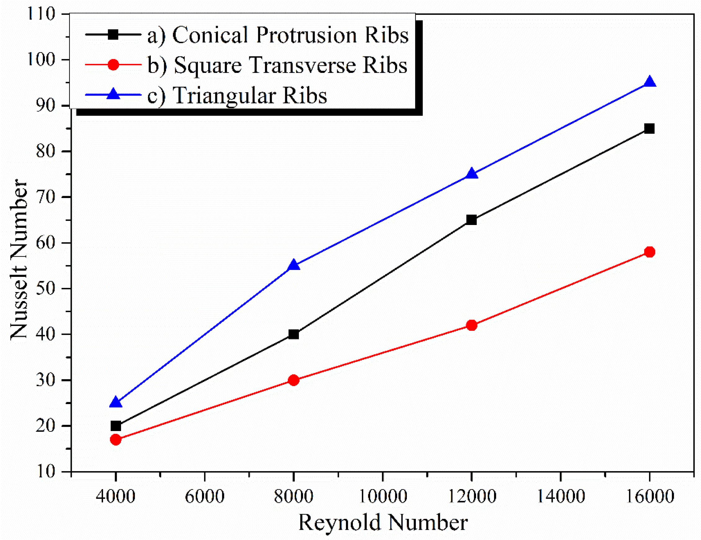
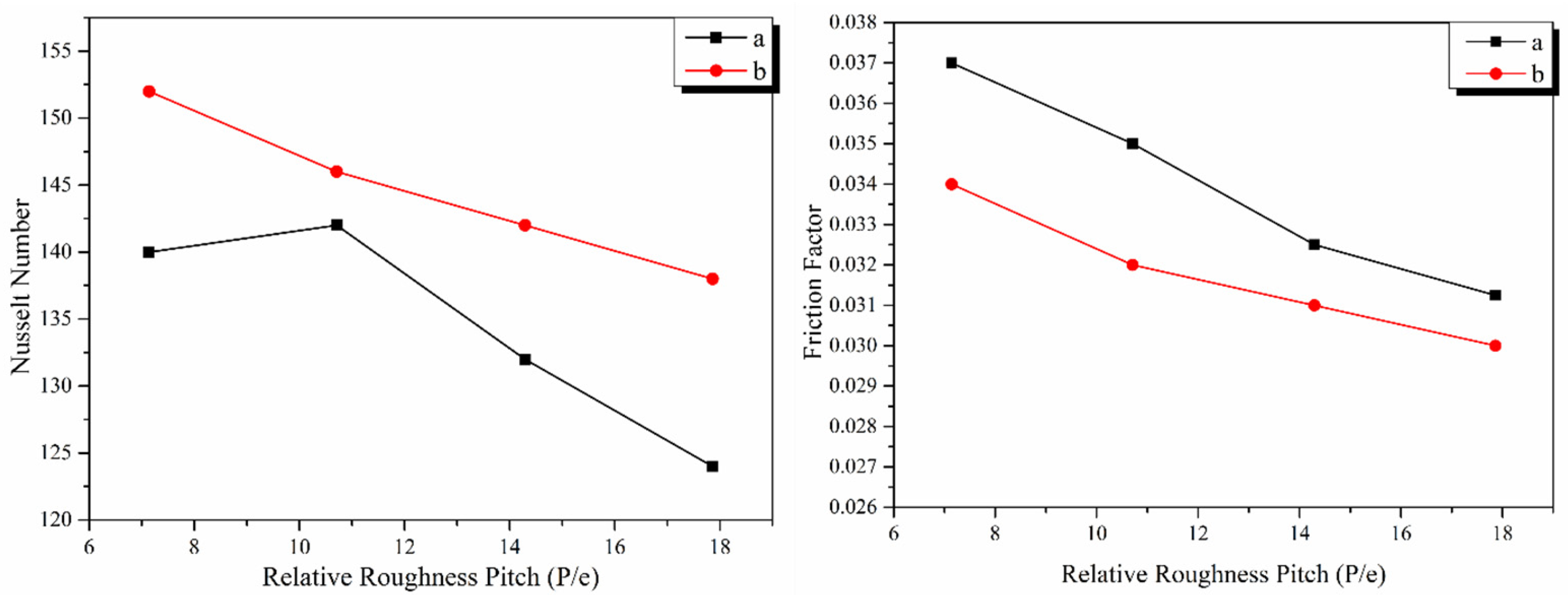
Figure 17 describes the effect of the relative roughness pitch of ribs on the Nusselt number and friction factor. The increase in the relative roughness pitch allows the Nusselt number to increase up to an optimum value. The optimum value of p/e depends on the shape of the ribs/fins. As can be seen from Figure 17, the Nusselt number started to decrease with increments in p/e for square ribs, while in the case of triangular ribs, it first increased and then started to decrease. The reduction in the Nusselt number is due to the reason that the number of fins/ribs decreases with increments in p/e, which causes a reduction in the reattachment point (where air streamline attaches to the absorber wall again) over the absorber plate. For conical ribs and dimple-shaped ribs, the optimum p/e value was 10 for the maximum Nusselt number [44,66]. In the case of the friction factor, obstruction to the air flow reduces by enhancing the p/e, which allows the friction factor to reduce.

3.6.3. Geometry of Fins/Ribs

The geometry of the fins also has an impact on the thermal performance enhancement. Labed and Moummi [29] showed that trapezoidal fins had better thermal performance in double- and single-pass solar air collectors than rectangular fins.
Hosseini et al. [67] concluded that rectangular fins had better thermal performance compared to triangular and elliptical fins. Kumar and Chand [31] numerically found that the thermal efficiency and pressure drop were enhanced by reducing the herringbone fin pitch as the number of fins was increased by reducing the fin pitch. Also, the thermal efficiency was raised by reducing the fin spacing ratio (Fp/2A). It was observed that the mass flow rate should not exceed 0.05 kg/s since the pressure drop dominates the positive effect of increased thermal efficiency at high mass flow rates. Chand and Chand [52] found that the thermal efficiency and outlet air temperature were enhanced by decreasing louvered fin spacing. Effective efficiency was raised up to an optimum mass flow rate. It was also found that the increase in fin height and duct height caused higher pressure drops with a reduced heat removal factor.
Saravanan and Murugan [68] studied the effect of geometric parameters of C-shaped fins on the thermal performance of solar air collectors. The Nusselt number and friction factor correlations were developed based on the results that the heat transfer was enhanced by raising the pitch-to-gap ratio (P/g) and relative height ratio (h/H) (up to an optimum value), respectively. On the other hand, the friction factor was reduced by increasing the pitch-to-gap ratio (P/g) and reducing the relative height ratio (h/H), respectively. The empirical correlation was developed based on the Nu number and friction factor dependency on the relative pitch ratio and height ratio, respectively, as shown in Equations (16)–(19).
Non-perforated fins:
N u n p = 0.009 R e 0.861 P g 1.009 h H 0.482   E r r o r : ± 9.63 %   3000 R e 24000
f n p = 1.126 R e 0.194 P g 0.757 h H 0.593   E r r o r : ± 9.44 %   3000 R e 24000
perforated fins:
N u p = 0.527 R e 0.85 P g 1.009 h H 1.076 h d p 2.484   ± 9.53 %   3000 R e 24000
f n p = 0.21 R e 0.21 P g 0.782 h H 0.502 h d p 1.084   ± 8.73 %   3000 R e 24000
Saravanakumar, Somasundaram, and Matheswaran [69] studied the combined effect of baffle, fins, and artificial roughness on the exergy performance of solar collectors, as shown in Figure 18. It was found that the exergy efficiency increased and exergy destruction decreased by increasing the number of fins and the baffle width and decreasing the length of the baffle, respectively. The optimum values for the baffle length, width, and number of fins were found to be 0.015 m, 0.2 m, and 8, respectively.
Benhamza and Boubekri [70] found L/W = 1.28, D2 = 0.067 m, and N = 49 as the optimum geometric parameters for a solar air heater with fins using the response surface methodology (RSM). It was found that the outlet air temperature increased by raising the aspect ratio (L/W) and reducing the duct height of air (D2), while thermal efficiency was not significantly affected by the aspect ratio and duct height.
The addition of ribs/fins allows heat transfer to be enhanced at the expense of increased pumping power. The use of artificial roughness, fins, and ribs should be achieved in such a way that it provides maximum heat transfer at the expense of the minimum pressure drop or friction factor. It is fulfilled by evaluating the friction factor and heat transfer simultaneously, which is provided by the parameter known as the thermal hydraulic performance parameter (THPP) [71]:
T H P P = N u r N u s f r f s 1 3
where Nur and Nus are the Nusselt numbers for roughened and flat surfaces, respectively. fr and fs are the friction factors for roughened and smooth surfaces. A THPP greater than unity indicates that an absorber with fins/ribs/roughness is potentially beneficial [72]. Table 1 shows the thermal hydraulic performance parameters of different ribs.

3.6.4. Absorber with Baffles

Another option for enhancing the thermal performance of SACs is the use of baffles, which are responsible for creating turbulence effects for high heat transfer rates.

Baffle Width and Height

The heat transfer can be increased by enhancing the turbulence inside the system, which can be achieved by increasing the width of the baffle [69,80]. An increase in the baffle width could enhance the exergy efficiency, while increasing the baffle length could have a negative impact on the exergy efficiency because increasing the length will result in a reduced number of baffles, which will minimize the turbulence effect and poor flow separation [69]. Mousavi et al. [81] found that the Nusselt number increases with an increase in the baffle height up to an optimum point.

Baffle Position

Yeh and Lin [82] suggested using the baffle at the center of the collector to achieve maximum thermal performance, while Bensaci et al. [83] suggested installing the baffle on the whole area of the absorber to achieve maximum thermal performance. Hu and Liu [84] numerically studied the effect of the first baffle’s position on the performance of SACs. It was found that the heat transfer in SACs could be enhanced by reducing the gap between the first baffle and the inlet section up to an optimal distance. The thermal efficiency was increased by 16.90% by reducing the distance to 200 mm between the inlet and the first baffle. Bayrak, Oztop, and Hepbasli [85] showed that baffles arranged in a staggered way had a greater impact on the energy and exergy efficiency than non-staggered baffles because dead zones were reduced with induced turbulence in the staggered arrangement of baffles. It was also found that the thickness of the baffle had an inverse relationship with the energy and exergy efficiency of SACs. Figure 19 shows the rectangular baffle used in [75].

Baffle Shapes

The shape of the baffle is responsible for enhancing the turbulent effect with an increased resident time of air in the collector. Using the V-shaped baffle at a 45° angle achieved a thermal enhancement factor that was 2.6 times higher than that achieved at a transverse baffle at 90° [86]. In another study, a V-shaped baffle arranged in a staggered way provided a thermal enhancement factor 2.75 times higher than a V-shaped baffle pointing downstream [87]. The thermal enhancement factor was enhanced due to an increase in the Nusselt number. The use of a baffle generates the vortex flow throughout the collector channel, which allows better mixing of flow between the core regions and wall, resulting in an enhanced Nusselt number and friction factor [88].
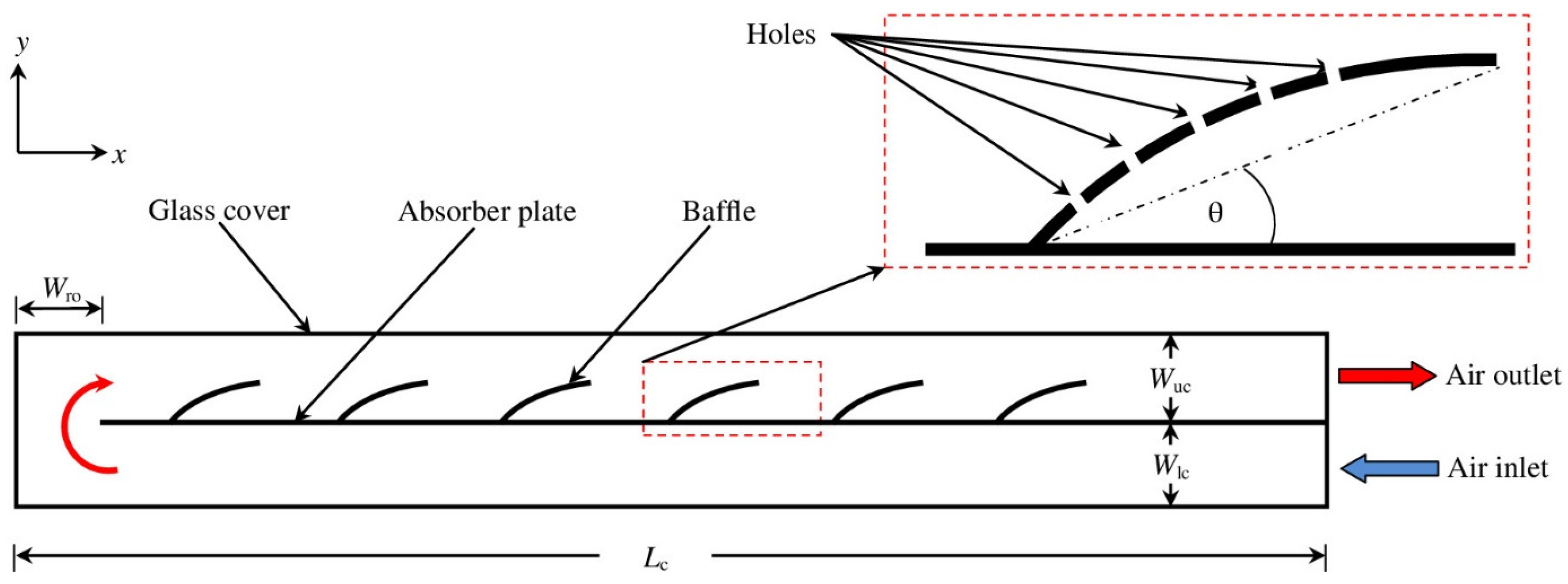
El-Said [89] numerically studied the heat transfer behavior of air in a perforated baffle attached to an absorber plate (shown in Figure 20) at a certain angle using Navier–Stokes and energy equations. It was found that the thermal efficiency and outlet temperature increased and pressure was decreased by enhancing the hole diameter of the baffle, while both parameters reduced by raising the baffle inclination angle to a maximum efficiency of 77%, which was achieved at a 3 mm diameter, 7° angle, and 0.07 kg/s flow rate.
Fiuk and Dutkowski [90] conducted experiments on a flat-plate solar air collector under natural convection using wave-like baffles in two different ways (inline wave-shaped baffles as type I and staggered wave-shaped type II), as shown in Figure 21. It was found that the air temperature, inlet air velocity, and thermal efficiency increased with increments in the solar radiation. A maximum thermal efficiency of 73.8% was achieved using wave-shaped type 1 baffles.
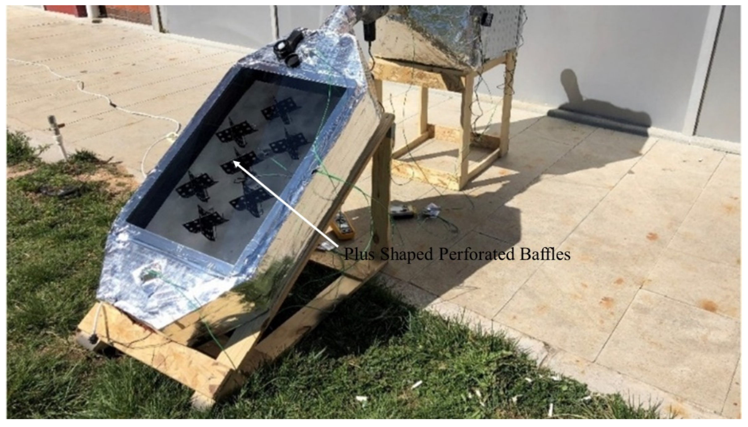
Khanlari and Güler [91] found that high thermal performance was achieved using a parallel pass with plus-shaped baffles on both sides (as shown in Figure 22) of the collector because the residence time of air in the collector increased due to the baffles, which allowed maximum thermal energy extraction from the absorber plate from both sides.
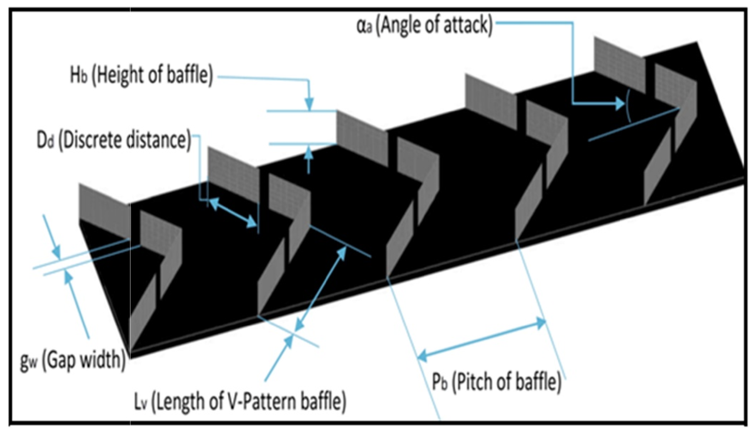
Kumar and Sethi [92] found that the Nu number and friction factor were enhanced by enhancing H b H , P b H , g w H b , α   a n d   D d L v up to an optimum value using a broken V-shaped discretized baffle. A schematic of the discretized V-shaped baffle is illustrated in Figure 23.
Chamoli and Thakur [93] found that the Nu number was enhanced by raising p/e (up to an optimum value of 2.5) and e/H, while the Nu number was reduced with increments in an open area ratio using perforated V-shaped baffles in a solar air collector. Based on these results, a correlation was developed as a function of the Reynold number, relative roughness pitch, relative roughness height, and the open area ratio as follows:
N u = 0.0296 R e 0.7848 P e 0.3007 e H 0.6774 β 0.3571 exp 0.2548 ln P e 2 × exp 0.4406 ln e H 2 exp 0.0863 ln β 2 , 4100 R e 18500
where p/e is the relative roughness pitch, e/H is the relative roughness height, and β is the open area ratio.
It was suggested to keep the baffle hole close to the absorber surface because a hole near the surface creates a jet impinging effect of air to the absorber surface, resulting in an enhanced heat transfer rate. A correlation for the friction factor was also developed based on the results that the friction factor decreases with increases in the Re number, relative to the roughness pitch, open area ratio, and decreases in the relative roughness height, as given in Equation (22).
f = 0.632 R e 0.18 P e 0.16 e H 1.05 β 0.13   , 4100 R e 18500
In a similar study, Bopche and Tandale [94] developed a correlation (given in Equation (23)) for the Nusselt number based on results that showed the Nusselt number to be reduced by raising the relative roughness pitch (p/e) in a U-shaped turbulator, decreasing the Reynold number and relative turbulator height to a hydraulic diameter ratio (e/Dh).
N u = 0.5429 R e 0.7054 p e 0.1592 e D h 0.3619   , 3800 R e 18000
Furthermore, a correlation for the friction factor was also developed based on the results that the friction factor decreases with an increase in the Reynold number and relative roughness pitch, as given in Equation (24).
f = 1.2134 R e 0.2076 p e 0.1592 e D h 0.3285 ,   3800 R e 18000
It was suggested that the sharpness and number of edges of a turbulator helped to enhance the heat transfer rate by shearing the viscous boundary layer compared to ribs with one edge. Karwa and Maheshwari [95] suggested that half-perforated baffles had better thermal hydraulic performance than fully perforated baffles.
From the abovementioned review, the heat transfer enhancement of baffles is strongly proven in solar collectors. Certain modifications in baffle design can provide a jet impinging effect to achieve high thermal performance of the system. The jet impinging of flow into the walls helps to induce high turbulence along with the generation of eddies, but it comes at the price of an increased pumping power due to the high pressure drop. Table 2 summarizes the average Nusselt number and friction factor enhancement using a baffle compared to a flat-plate.

3.6.5. V-Groove/Corrugated/Sinusoidal Absorber

Another possible absorber design is the use of V-grooves or trapezoidal-shaped absorbers, which are lower in cost compared to fins, ribs, and baffles. These absorbers have a larger heat transfer surface area compared to flat-plates.
Sparrow and Lin [106] found that the V-grooved cavity absorbs a greater quantity of direct beam or diffuse radiation than a flat surface of the same absorptivity. Hollands [107] also studied the effect of direct radiation on V-corrugated surfaces and found similar results of enhanced heat absorption by V-corrugated compared to flat-plates. Goldstein Jr and Sparrow [108] and Parker and Lindley [109] showed that the average transfer coefficients for corrugated channels were high compared to flat-plate absorbers for laminar and turbulent flow. Hawlader et al. [110] showed that the efficiency of a solar collector can be improved by about 20–25% using a V-corrugated absorber.
Karim, Perez, and Amin [111] showed that the outlet temperature increased significantly by increasing the inlet air temperature in a V-groove counter flow solar air collector. Desisa and Shekata [112] numerically achieved 62%, 78%, and 90% thermal efficiency for flat-plate, rough-plate, and V-groove solar air collectors.
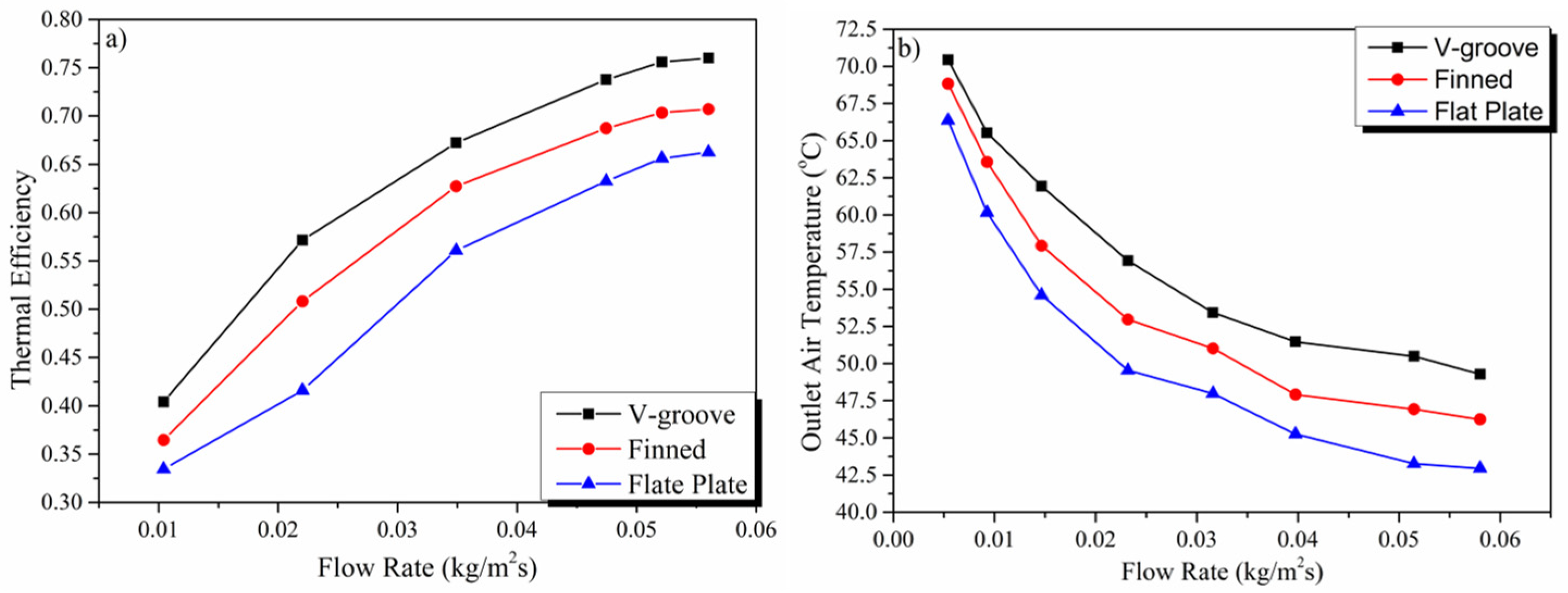
Karim and Hawlader [113,114] compared the thermal efficiency of V-groove, finned, and flat-plate absorbers, as shown in Figure 24. It was found that V-groove double-pass SAHs had higher thermal performance compared to finned and flat-plate SAHs. The V-groove absorber has the benefit of absorbing higher solar radiation due to multiple reflections and the absorption of solar radiation compared to finned and flat-plate absorbers. The thermal efficiency of V-groove double-pass SAHs was 7–12% and 5–9% higher than flat-plate and finned SAHs, respectively [115].
Zulkifle and Alwaeli [116] found that the Fresnel lens outperformed the glass cover in terms of the outlet air temperature and thermal efficiency using a V-groove as the absorber. It was also noted that enhancing the wind velocity and Reynold number caused a reduction in the overall temperature of the collector. Ho and Hsiao [117] found that the performance of SACs was enhanced using a V-groove stainless steel absorber, and the recycling ratio increased from 0.25 to 2. El-Sebaii and Aboul-Enein [37] found that the overall heat losses were reduced using a V-corrugated solar air collector compared to a flat-plate collector because of the large heat transfer area of the V-corrugated absorber, which allows air to extract more heat from the absorber. The thermo-hydraulic efficiency of V-corrugated SACs was 14% greater than that of flat-plates.
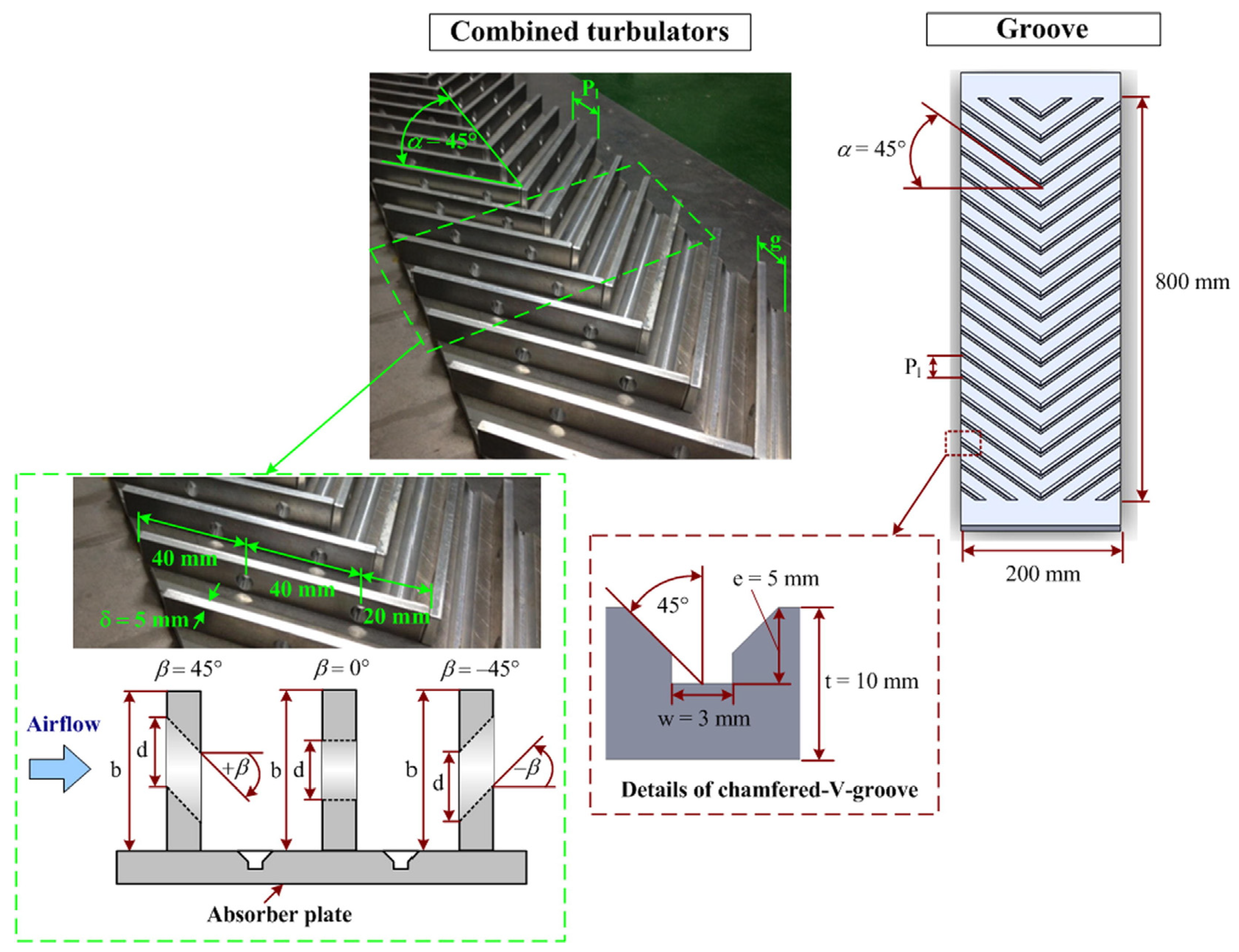
Sudhakar and Cheralathan [118] achieved a maximum heat transfer coefficient and exergy efficiency of 61.6 W/m2K and 3.6% using a V-groove absorber integrated with fins, respectively. Eswaramoorthy [119] found that the high temperatures at the connection were not desirable due to increased stress, which can lead to stress failure. Liu and Lin [120] found that the cross-corrugated absorber was 7.5% better than the V-groove solar air collector. It was suggested that the glass cover and absorbing plate emissivity should be low with a high absorptivity, and also that the length of the collector should be greater than its width to achieve the maximum thermal output. Promvonge and Skullong [121] studied the combined effect of the V-groove and punched V ribs on the performance of SAHs, as shown in Figure 25. The results showed that the Nu number and friction factor were enhanced by reducing the relative rib-to-groove pitch ratio for V-up and V-down punched ribs with V-grooves, and correlations were developed based on these results for the Nusselt number and friction factor given in Equations (25)–(32). The V-up turbulator had better performance than the V-down turbulator due to the generation of jet impinging flow area, which resulted in an enhanced heat transfer. It was suggested to use a downward hole inclination angle to gain an impinging jet on the absorber surface. The empirical correlations are given as follows:
Combined punched V-rib and chamfered V-groove and V-down ( 5300 R e 23000 ) :
N u = 0.238 R e 0.724   P r 0.4 90 + β 0.042 R P 0.23   ; E r r o r   ± 10 %  
f = 1.147 R e 0.052 90 + β 0.068 R p 0.623   ; E r r o r   ± 10 %  
V-groove alone and V-down ( 5300 R e 23000 ) :
N u = 0.274 R e 0.629 P r 0.4 R p 0.516 ;   E r r o r   ± 10 %  
f = 3.809 R e 0.292 R p 1.448   ;   E r r o r   ± 10 %  
Combined punched V-rib and chamfered V-groove and V-up ( 5300 R e 23000 ) :
N u = 0.264 R e 0.72 P r 0.4 90 + β 0.045 R p 0.211 ;   E r r o r   ± 6.7 %
f = 1.302 R e 0.055 90 + β 0.056 R p 0.583 ; E r r o r   ± 8 %  
V-groove alone and-up ( 5300 R e 23000 ) :
N u = 0.252 R e 0.652 P r 0.4 R p 0.467 ;   E r r o r   ± 6.7 %  
f = 3.014 R e 0.248 R p 1.232   ;   E r r o r   ± 8 %  
where R e is the Reynold number, P r   is the Prandtl number, R p is the relative rib/grove pitch ratio, and β is the hole inclination angle.
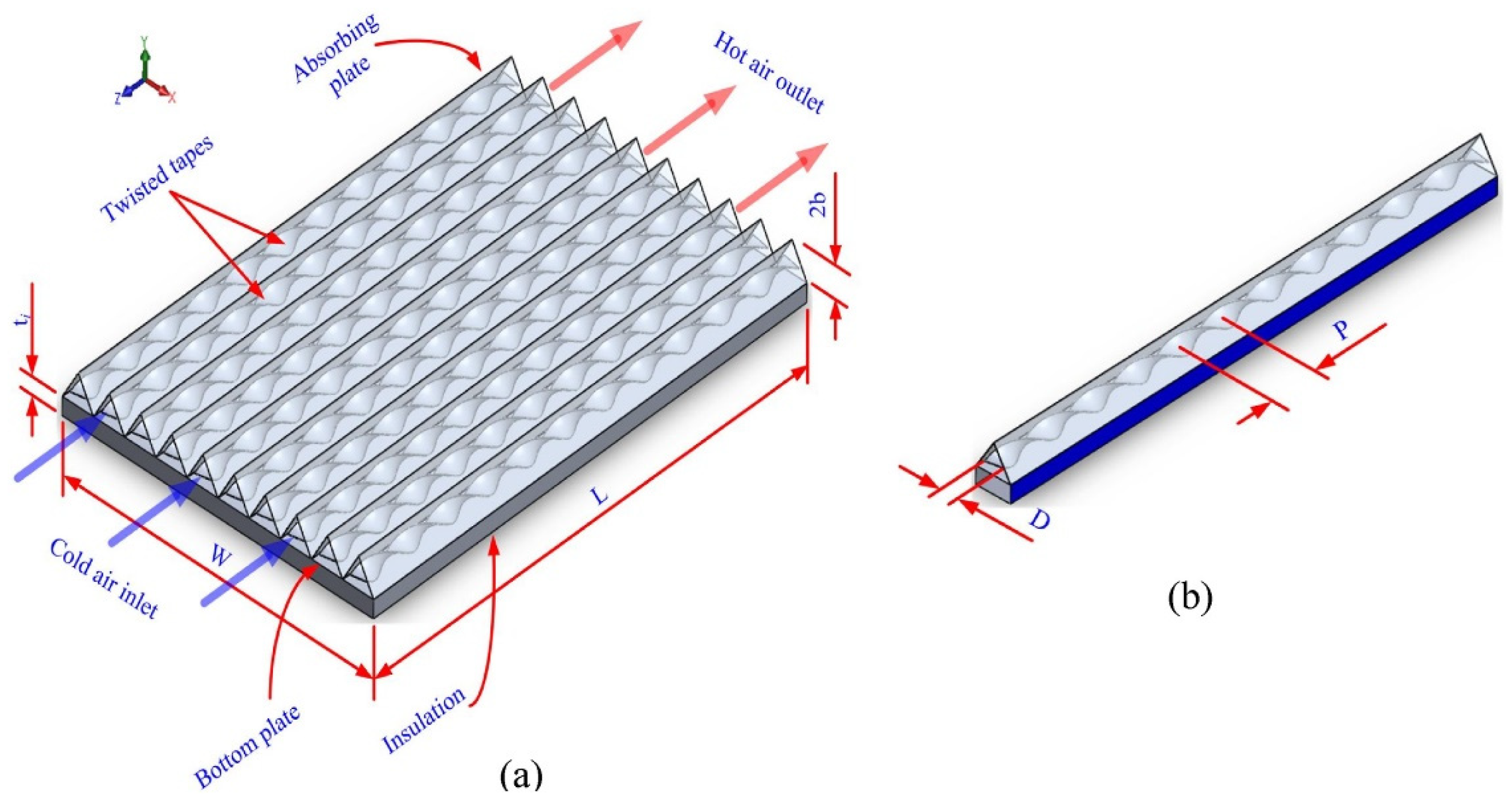
Lakshmi, Layek, and Kumar [122] found that trapezoidal solar air collectors had better thermal performance compared to flat-plate solar air collectors because of the large heat transfer area of the trapezoidal solar air collector. Reddy, Das, and Negi [35] found that cross-corrugated SACs showed much better performance in terms of the environment, energy, and exergy efficiency compared to the reverse trapezoidal absorber because of the enhanced turbulence effect caused by the formation of eddies, which resulted in an enhanced heat transfer rate. Also, it was found that the performance of solar collectors was enhanced by increasing the tilt angle. Salih, Alomar, and Yassien [123] showed that the trapezoidal absorber with packed bed porous media had better performance under a natural convection in terms of the thermal efficiency, outlet air temperature, and useful energy gain compared to a forced convection. It was found that the trapezoidal solar air collector with porous media had superior performance compared to the non-porous trapezoidal solar air collector. Farhan et al. [124] studied the effect of the twisted tape insert (twist ratio Y) on the V-corrugated absorber. It was found that the thermal efficiency and exergy efficiency were enhanced by reducing the twisted tape ratio (Y). The twisted tape ratio is defined as follows:
Y = P D  
where P is the twisted tape pitch for 180 deg rotation and D is the twist tape height. A schematic of V-corrugated with twisted tape is shown in Figure 26.
Hassan et al. [125] showed that perforated corrugated SACs had better thermal performance compared to corrugated and flat-plate SACs due to the induction of turbulence in perforated SACs. In a different study, fins were employed on a V-corrugated absorber and achieved higher thermal efficiency compared to flat-plate and corrugated SACs [126]. Manjunath et al. [127] studied the effect of the wavelength of a sinusoidal absorber on the effective efficiency and pumping power. An increment in the wavelength enhances the effective efficiency because of the reduced obstruction, which allows the pressure drop to be reduced.
Lingayat and Chandramohan [128] found that the thermal hydraulic performance parameter (THPP) increases with increments in the corrugation angle up to an optimum angle. The maximum THPP achieved was 1.83 at θ = 20 ° and a corrugation height of 1 cm.
It can be concluded that V-groove, corrugated, or trapezoidal-shaped absorbers combined with fins or ribs have high thermal performance. Due to the induction of re-circulation, reverse flow (reverse flow refers to the unexpected reversal of air flow direction caused by the disruption in geometry and sudden changes in pressure), and a thin boundary layer in the groove channel, the heat transfer will increase, leading to higher temperature gradients. However, in terms of technology, it suffers from high machining costs; therefore, manufacturing comes as a challenge in commercial applications.

3.6.6. Single- and Multi-Pass Collectors

A more commercialized option to increase the heat transfer rate in SACs is to use multi-pass collectors, which allow air to be exposed for a longer time with the absorber.
Chandra, Singh, and Sodha [129] achieved outlet air temperatures of 90–101 °C using a triple-pass solar air collector. The high complexity and costs for multi-pass solar air collectors restrict their use in commercial applications [130]. A double-pass porous matrix air heater was analyzed by Mohamad [131] and achieved a thermal efficiency of 75% using double-pass porous matrix SAHs.
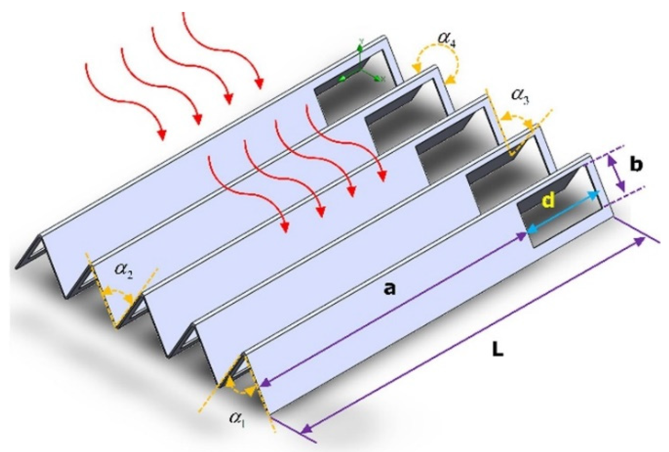
Ramani, Gupta, and Kumar [132] showed that the thermal performance of solar collectors can be enhanced by passing the air between two glasses before flowing over the absorber; this can help preheat the air and reduce heat losses to the surrounding. The thermal performance was enhanced by 35% using a porous medium with double-pass counter flow using two glasses compared to a conventional double-pass collector. Razak and Majid [133] designed four different cross-matrix absorbers (CMAs) to analyze their performance in a single-pass solar air collector, named ladder, parallel, simple, and compact, according to their design configurations. CMAs with a ladder configuration had the highest efficiency (76%), temperature elevation (15.3 °C), thermal capacity (38.7 kJ), and minimum pressure drop (1.33 Pa). Yang and Wang [134] studied the effect of five parameters (thermal resistance, stagnant air height, transmittance of collector, absorber plate emittance, and back plate conductive thermal resistance) on the performance of single-pass solar air collectors. The results showed that the thermal efficiency was most improved by decreasing the thermal resistance using fins. Increasing the stagnant air height and transmittance of the collector had the second most positive impact on thermal efficiency, while no significant effect was noted in the case of other parameters. Tuncer and Sözen [135] used computational fluid dynamics and k ε as the turbulent model for designing quadruple-pass solar air collectors along with a greenhouse dryer and then validated it with experimental results. The maximum instantaneous temperature difference gained was 28.10 °C at 0.008 kg/s, while the maximum instantaneous efficiency gained was 90.30% at 0.010 kg/s. Ho and Chang [136] showed that the thermal performance was increased by lowering the flow rate and enhancing the recycling ratio using double-pass cross-corrugated solar air collectors. MesgarPour, Heydari, and Wongwises [137] numerically optimized the geometric parameters (as shown in Figure 27) of a triangular-shaped absorber of solar air heaters. According to their results, the optimized parameters found were α 1 α 2 = 0.6 , α 3 α 4 = 0.8 , a L = 0.73 , and b d = 0.67 . At the optimized geometric parameter, efficiency not only improved by 14.52%, but the pressure drop also decreased with a decrease in inactive vortices. The efficiency and Nusselt number were increased by increasing the Reynold number up to an optimum value.
Alic, Das, and Akpinar [138] found the Z-type absorber to be the best among three other absorber models (shown in Figure 28) in terms of the outlet temperature and thermal and exergy efficiency because the Z-type had the largest heat transfer area and created a higher turbulence. The highest thermal and exergy efficiencies were found to be 78% and 4.7% for Z-type.
Nowzari, Aldabbagh, and Egelioglu [139] designed two separate quarter-perforated covers with 10D and 20D (D = 3 and 6 cm distance between each hole) for single- and double-pass solar air collectors, respectively. The results showed that there was no significant enhancement in the temperature difference using a perforated cover in the single-pass solar air collector due to the mixing of ambient air with air flowing through the collector, which reduced the overall temperature of air. A total of 54.76% and 51.70% thermal efficiencies were achieved for the 10D perforated cover and normal glazing for double-pass solar air collectors. Fudholi and Ruslan [140] numerically achieved a thermal efficiency of 72% at I = 790 W/m2 and 0.09 kg/s flow rates for double-pass solar air collectors.
Increased pressure drops are predicted when the number of passes increases. Therefore, as a trade-off between the pressure drop and heat transfer, double-pass designs are more feasible and better recognized in the commercial scope.

4. Exergy Analysis

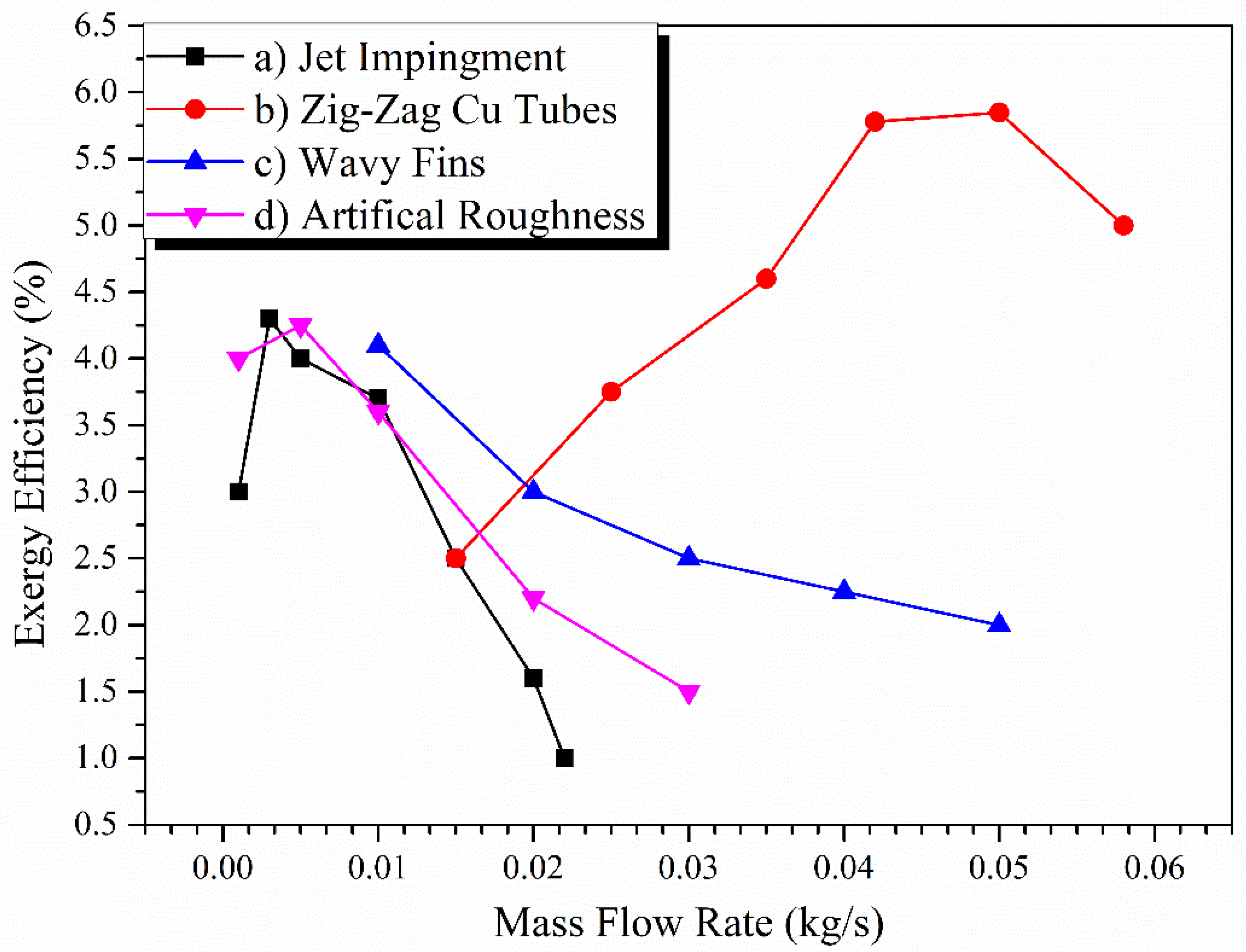
Consideration of the thermal efficiency deduced from the first law of thermodynamics is a conventional as well as vital part of any collector analysis but does not give the perception of available work and irreversibility, which reduce the sustainability of the process [141]. Therefore, an exergetic analysis of the process provides a practical sense of the losses, irreversibility, optimizing potential, and availability of wasted energy streams [142]. Exergy is an indicator of how much useful energy is available to the system that can be directly utilized for certain applications, such as drying. Exergy efficiency is related to exergetic losses and is commonly lower compared to the thermal efficiency due to the entropy generated in the system by heat losses, pressure losses, and frictional losses. The maximum exergy loss occurs at the absorber plate due to sun exergy destruction. It was found that it is almost impossible to avoid the majority of exergy annihilation from the absorber plate [143]. Exergy efficiency is mainly dependent on the mass flow rate, solar radiation, outlet air temperature, temperature rise parameters, and absorber plate temperature. Figure 29 shows the effect of the mass flow rate on the exergy efficiency. The exergy efficiency increases with an increase in the mass flow rate up to an optimum condition. This is because exergy efficiency is more dependent on the outlet air temperature rather than the mass flow rate. The outlet temperature of air is high at low flow rates, which results in higher exergy efficiency. As soon as the flow rate increases, the outlet temperature of the air decreases, resulting in a decrease in exergy efficiency after the optimum point. For the results presented in Figure 29, studies [144,145,146] are numerical investigations, while [147] is an experimental study that showed a different trend. The numerical investigations showed that exergy efficiency starts to decrease at lower flow rates, while experimental investigations demonstrated an inverse trend, as shown in Figure 29.
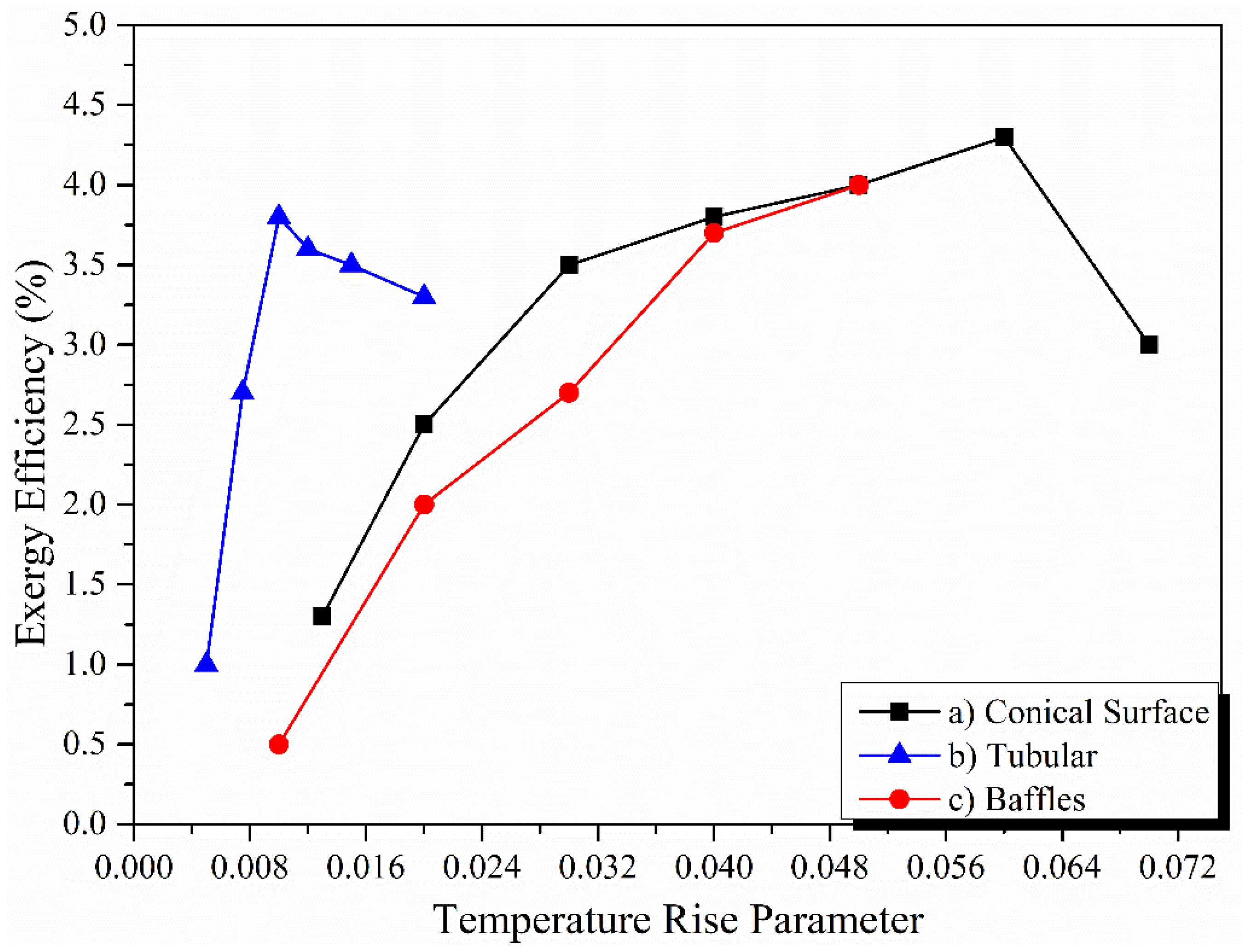
Figure 30 shows the effect of temperature rise parameters on exergy efficiency. Temperature rise parameters are a function of the outlet air temperature. The greater the temperature rise parameter, the greater the outlet air temperature, which results in an increase in exergy efficiency.
Matheswaran, Arjunan, and Somasundaram [144] numerically studied the effect of a single-pass double jet plate on the exergy efficiency of a solar air heater (the schematic is shown in Figure 31). It was found that the exergy efficiency was increased by the increase in the span wise ( X D h ) and stream-wise pitch ratio ( Y D h ) for laminar flow, while it was suggested to use low ( X D h ) and ( Y D h ) ratios.
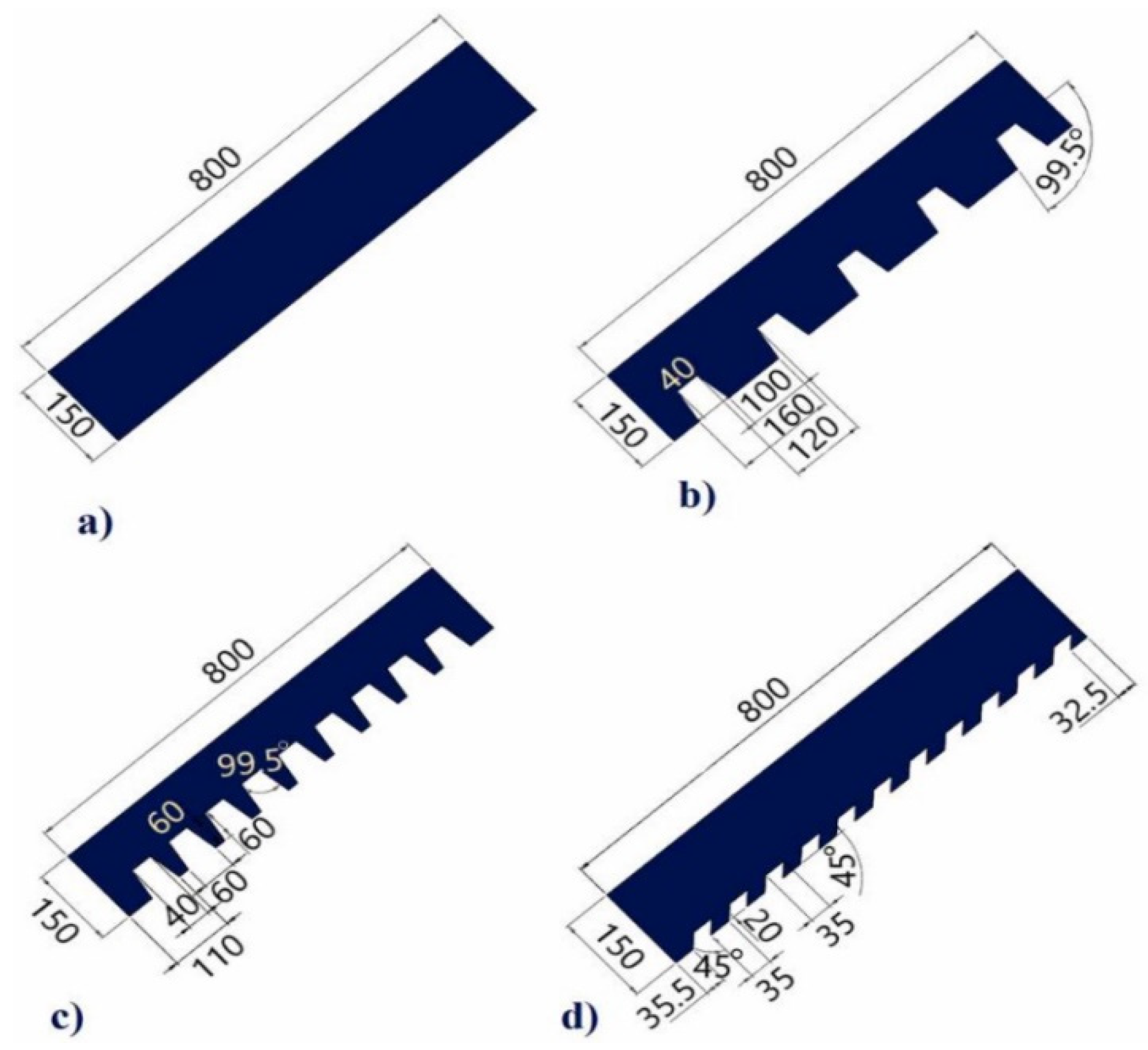
Abuşka [148] extended the surface area and reduced the dead zones in the duct and shading area by applying a conical surface on the absorber plate, which helped enhance exergy efficiency compared to the flat-plate solar air collector. Luan and Phu [151] studied the effect of a baffle angle (0°–180°) on exergy and effective efficiency, as shown in Figure 32. Both efficiencies have a similar trend, showing maximum efficiencies between 60 and 120°, while above 120° and below 60°, both the efficiencies have a declining trend. This is because a baffle angle between 60 and 120° provides higher obstruction to the air flow, helping to create a higher turbulent effect. As soon as the turbulence effect increases, the heat transfer increases.
Gupta and Kaushik [152] studied the effect of the duct height (H), area of collector (G), aspect ratio (AR), and inlet temperature on the performance of a flat-plate solar air collector in terms of the energy and exergy outputs. To achieve a high energy output, high G and AR and a low inlet temperature and duct height were recommended. But in terms of the exergy output, it was recommended to use a high G and H and low AR to achieve a high exergy output.
Kumar, Mahanta, and Kalita [147] found better performance of copper-tube solar air collectors compared to flat-plates in terms of the energy and exergy efficiency. It was noted that the waste energy ratio had an inverse effect on the sustainability index. Debnath, Das, and Randive [153] showed that the exergy destruction was reduced due to a decrease in top radiation and convection losses using double glazing. Also, exergy efficiency was enhanced by raising the mass flow rate and tilt angle. Sahu and Prasad [154] conducted an exergy evaluation using arc-shaped wires on the absorber plate. It was concluded that exergy efficiency was enhanced by raising the relative roughness height (e/D) and reducing the angle of attack. Also, exergy efficiency rose by increasing the Re number and temperature rise parameters up to an optimum point. Acır and Canlı [150] optimized energy and exergy efficiencies of solar air heaters using a grey rational analysis. Correlations for energy and exergy efficiencies were developed (given in Equations (34) and (35)) based on the conclusion that both efficiencies increased with an increase in the Re number and a decrease in increments of the obstacle angle of relief ( α ) and obstacle distance (L), as shown in Figure 33:
η I = 5.209 R e 0.45 L 0.193 α 0.125  
η I I = 10.324 R e 0.4 L 0.342 α 0.151  
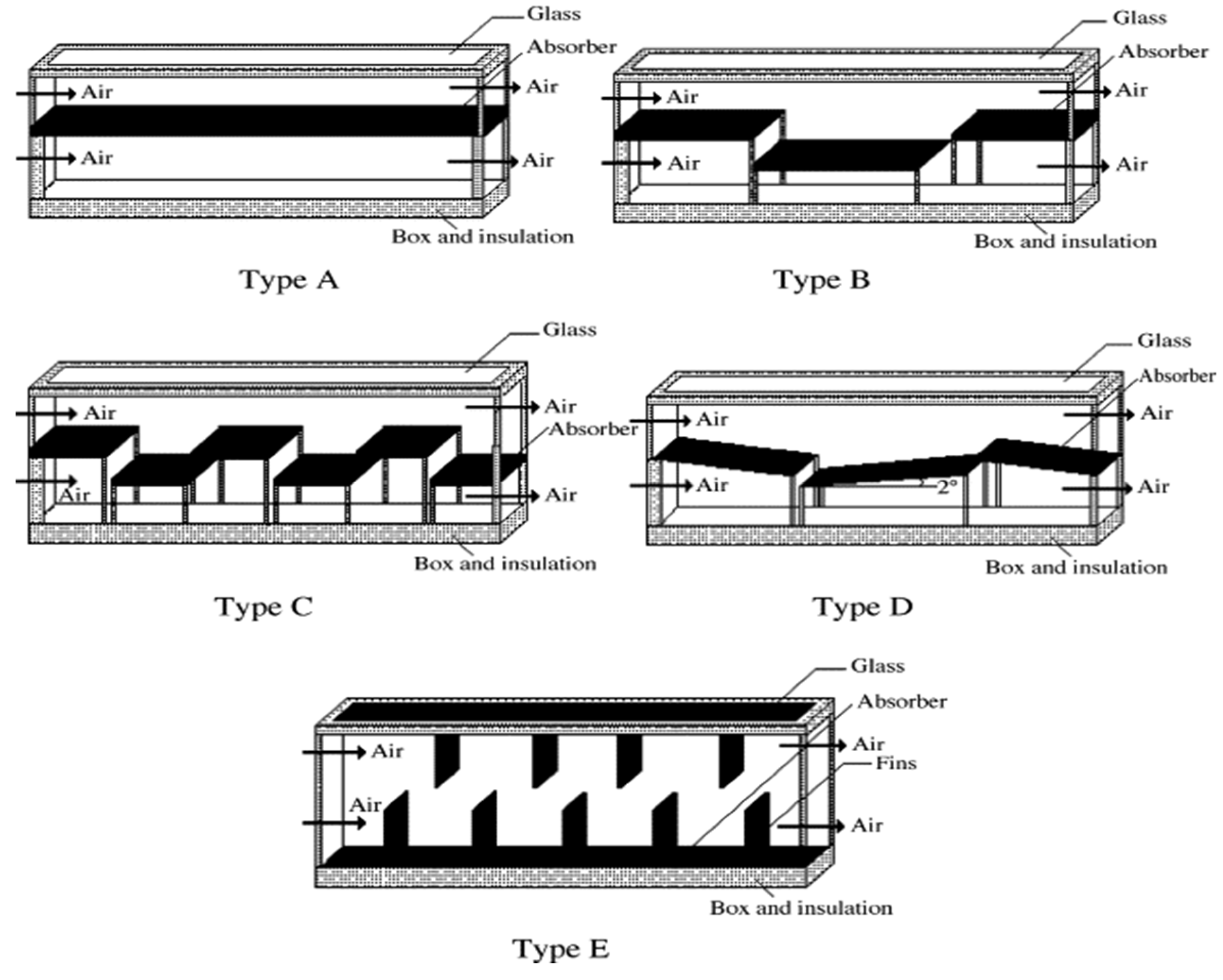
Ucar and Inallı [149] compared the performance of solar air collectors by changing the position of the absorber surface, as shown in Figure 34. From the results, the maximum enhancement in exergy efficiency was achieved by 25%, 30%, 15%, and 10% for absorber types B, C, D, and E compared to the flat-plate absorber.
Aktaş and Sözen [155] investigated the superior performance of multi-pass SACs with perforated fins (MSACPFs) compared to double-pass solar air collectors (DPSACs) in terms exergy efficiency but MSACPFs had a lower COP than DPSACs due to the greater fan power used in MSACPFs. Raam Dheep and Sreekumar [156] studied the effect of the flow rate on the exergy efficiency, sustainability index, and improvement potential. All the mentioned parameters had a positive effect with an increasing flow rate except for the improvement potential. Matheswaran, Arjunan, and Somasundaram [146] improved the yearly exergy and energy gains by 185.6% and 111.7% using a single-pass double-duct jet with artificial roughness (SPDD-AR) (arc-shaped). It was concluded that the SPDD-AR (arc-shaped) had higher performance than SPSD, SPDD-V-shaped baffle, metal grid roughness, combine inline transverse wire, and S-shaped roughness because the SPDD-AR destroys the formation of laminar sublayers, resulting in increasing reattachment points to enhance the heat transfer rate. Velmurugan and Kalaivanan [157] compared the performance of double-pass V-corrugated wire mesh longitudinal fins (type A), double-pass with longitudinal fins (type B), double-pass roughened with longitudinal fins (type C), and flat-plate collectors (type D). The performance observed in terms of energy efficiency, exergy gain, and temperature increment of air was in the following order: type A > type B > type C > type D because type A had a better turbulence effect along with a higher heat transfer area than the other studied configurations.

Entropy Generation and Exergy Destruction

In any thermodynamic process or system, entropy is generated during irreversible processes due to heat losses through thermal resistance, flow resistance, fluid viscosity, joule heating. and diffusion [158]. For solar air collectors, entropy can be evaluated using the following equation [159]:
S g e n = m ˙ C p l n T o u t T i n Q s T s + Q l o s s T a
Here, Q s is the useful heat gain, T s is the sun temperature, and Q l o s s is the total heat loss.
Q l o s s = Q s m ˙ C p T o u t T i n
The entropy generation is usually represented as the entropy generation number.
N s = S g e n T a Q s
The entropy generation or entropy generation number is generally affected by the mass flow rate, Reynold number, design of the system, temperature rise parameter, and solar radiation. The entropy generation number decreases with an increase in the Reynold number as the entropy generation number is directly related to the ratio of entropy generation to heat transfer. With an increase in the Re number, entropy generation increases, but the increase in heat transfer is high compared to entropy generation, which allows the entropy generation number to reduce [160,161].
Another factor affecting the entropy generation number is the temperature rise parameter. Figure 35 shows the effect of the temperature rise parameter (TRP) on the entropy generation number. It sharply decreases with an increase in the TRP up to an optimum point (depending on the absorber design) and then starts to increase sharply [162,163]. This means that outlet air temperature increases with an increment in TRP up to an optimum point; however, above an optimum, the solar intensity starts to decrease, which shows the insufficiencies available to the system and increases the entropy generation of the system.
In the case of finned solar air collectors, entropy generation decreases with increments in the number of fins and height of fins, respectively. The increased fins and height of the fins allow the outlet air temperature to increase, resulting in reduced entropy generation [56].
Priyam, Chand, and Sharma [145] found that exergy destruction was reduced by raising the cross-section aspect ratio and flow length ratio and reducing the fin spacing ratio of wavy finned solar air heaters. The reduction in dimensionless and irreversible losses with increments in the flow rate was also observed by Raam Dheep and Sreekumar [156]. Abo-Elfadl et al. [25] found that exergy destruction due to the heat loss between absorber and environment was reduced by enhancing the flow rate using tubular SAHs. Debnath, Das, and Randive [153] showed that exergy destruction was reduced due to decrements in the top radiation and convection losses using double glazing. Benli [164] found that the corrugated absorber had the maximum Nusselt number and minimum exergy loss, followed by trapeze, reverse corrugated, reverse trapeze, and flat base, respectively.
The summary of the above-discussed literature is mentioned in Table 3. The data presented in Table 3 show that the air mass flow rate is restricted to approximately 0.05 kg/s. The enhanced thermal efficiency above the flow rate of 0.05 kg/s has no benefit due to the increased pressure drop in the system and the low air temperature. Solar air heaters with fins, baffles, and ribs need to consider the optimum geometric parameters, such as height, width, relative pitch ratio, and relative width ratio, in order to avoid oversizing the system and higher losses in terms of pressure drop, pumping power, and friction. The optimized geometric parameters for ribs are different from those for fins and baffles.
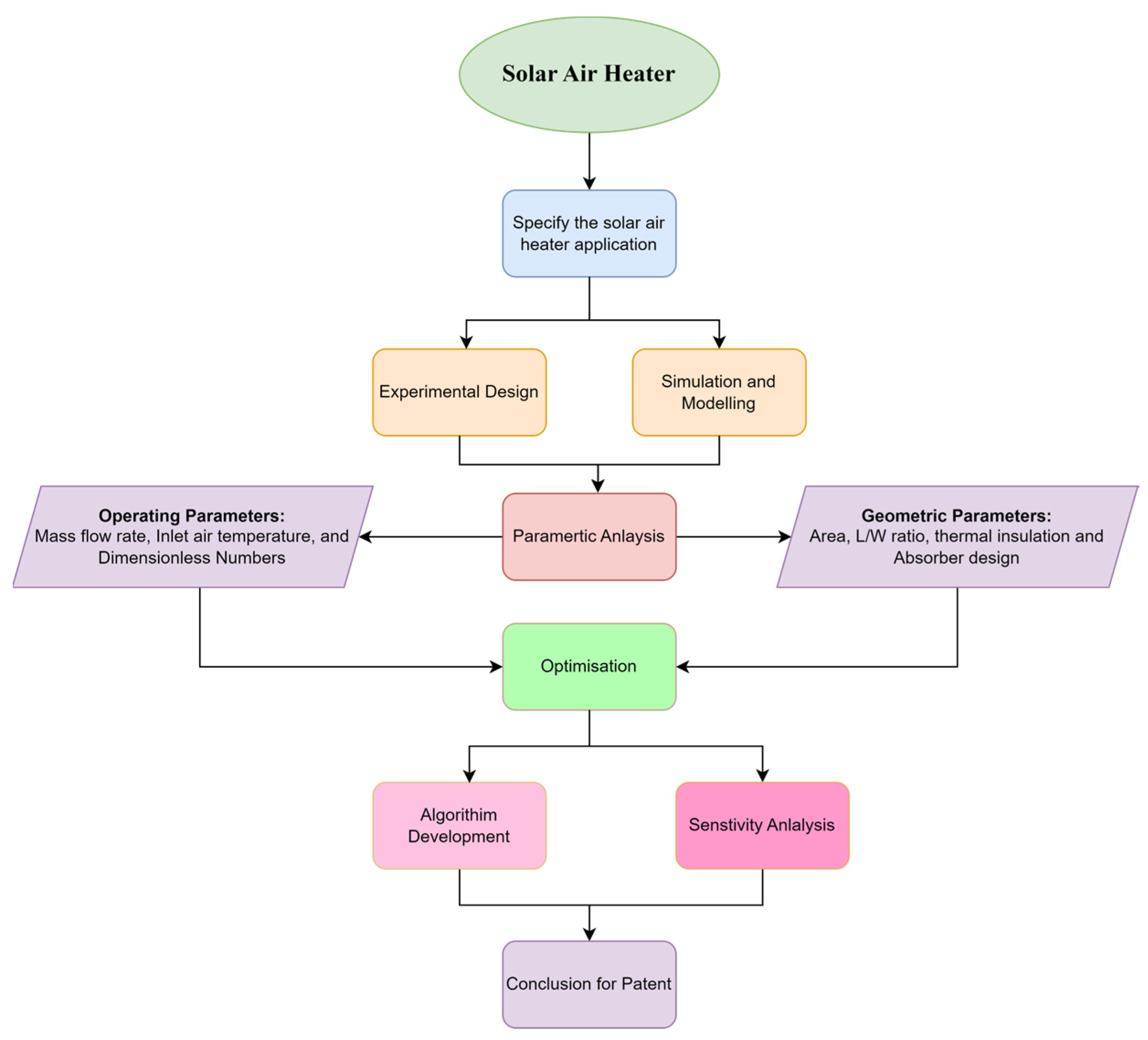
A methodology can be summarized based on the above-discussed literature to achieve a certain patent for a solar air heater. However, the derived methodology will differ from case to case; for example, the indirect solar air dryer methodology will differ compared to the space heating application. A simple methodology for optimizing the solar air heater performance is presented in Figure 36.

5. Outlook of Application of Solar Air Collectors in Industry

The global concern of this century is the rapidly changing climate and increases in the earth’s temperature. The world’s leaders are trying to shift energy sourcing toward renewable energy systems as the primary source of energy. Among various renewable energy systems, solar air collectors are the most common and simple in construction and can be used for various applications.

5.1. Space Heating and Cooling

Space heating and conditions are one of the major applications of solar air collectors for the residential sector. According to an international energy outlook, around 20% of the world’s energy is consumed by the residential sector [172]. Residential energy consumption includes space heating, cooling, water heating, and other thermal applications, such as cooking. Space heating and cooling are essential for the thermal comfort of residents as the productivity and satisfaction of the building’s occupants are highly dependent on thermal comfort [173]. The share of energy consumption for space heating and cooling depending on the climate varies from country to country. From 1990 to 2009, it was estimated that 82% of the stable share of natural gas was used for space heating in residential buildings [174]. Utilizing the solar air heater for space heating applications can provide an alternate solution of avoiding natural gas.
For space cooling, the solar-assisted desiccant cooling system (SADCS) provides an environmentally friendly option of cooling purposes. In SADCS, photovoltaic thermal collectors or solar air heaters are used for regenerating the desiccant by collecting the thermal energy. It is expected that the SADC can mitigate the local peak load [175]. Figure 37 shows the schematic of desiccant cooling systems assisted by solar air heaters. Table 4 has discussed some studies of solar air heater applications in desiccant cooling systems.

5.2. Drying

Another major application of solar air collectors is the drying of agricultural products. Drying involves convective heat transfer to remove excess of water to reduce food waste and enhance the shelf life of a product. The removal of water in drying is evaluated in terms of the moisture content either on a wet or a dry basis. Other important parameters in drying using solar air heaters are the specific energy consumption (SEC), drying temperature, collector efficiency, and dryer efficiency. Table 5 shows a summary of some of the studies on drying different products using different types of solar drying systems.

5.3. Water Desalination Using Humidification–Dehumidification

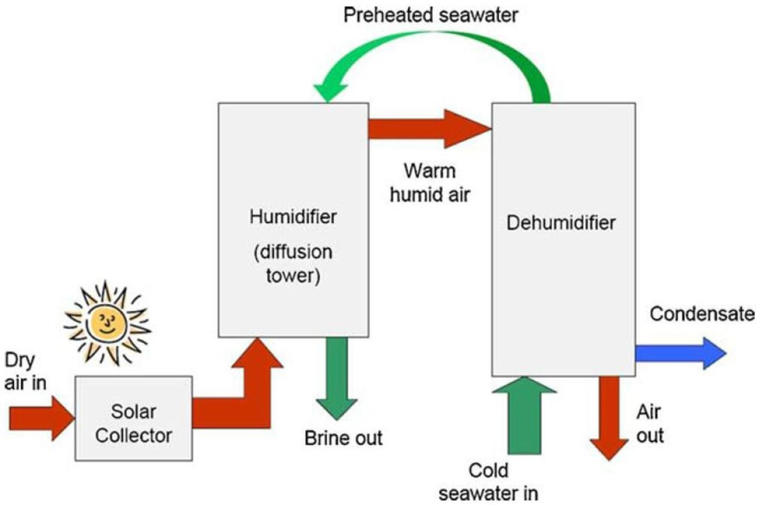
Solar air heaters can also be used for water desalination. This involves the humidification of air inside a humidifier followed by dehumidification in a condenser. The productivity of HDH for water desalination depends on the humidification ability of air. The humidification capacity of air increases with increments in the air temperature, which can be increased using solar air heaters [194]. A schematic of HDH for water desalination is shown in Figure 38.

5.4. Thermal Energy Storage

Due to intermittency and the weather dependency of solar energy, it is essential to integrate solar air heaters with the thermal storage system to provide thermal energy during off-peak solar radiation e.g., night-time. Thermal energy storage used in solar air heaters is either sensible or latent heat storage, as shown in Figure 39.

6. Conclusions

This article presents a comprehensive review of the improvements in thermal performance of solar air collectors made by modifications to the absorber design. Thermal performance can be enhanced by improving the thermal properties of fluids, enhancing the absorption area, and changing the flow regime (laminar to turbulent) in any system. In the case of solar air collectors, the thermal properties of air cannot be changed, but several designs can be modified for the absorber to increase the heat transfer rate. In practice, such absorber designs include employing fins and ribs to the absorber, adding baffles on the absorber surface to the air flow path, changing the shape from flat-plate to V-groove, and using cross-corrugated and trapezoidal. Based on the design of the absorber, the effect of the flow rate, geometric parameters, and Re number on thermal performance of SAC has been reviewed. The following conclusions have been drawn from this study:
  • The thermal efficiency of SasC increases with an increase in the mass flow rate, though the increase rate stops at a higher flow rate due to the increased pumping power demand and decreased outlet temperature with an increase in the flow rate. From the literature review, it is recommended to maintain mass flow rates between 0.01 and 0.05 kg/s to achieve the desired thermal performance. Above 0.05 kg/s, a very small enhancement in thermal efficiency is expected with a low outlet air temperature. By changing the shape/Design of the absorber, thermal efficiency and outlet temperature can be increased from 40% to 90% and 35 to 83 °C, respectively.
  • Conical fins provide higher thermal efficiency at around 83.6% compared to herringbone, longitudinal, and rectangular fins.
  • Exergy efficiency of the system increases with increases in the mass flow rate, within a range of 0.005 to 0.01 kg/s in numerical perditions and between 0.04 and 0.05 kg/s in experimental reports. Numerical studies have shown the optimum mass flow rate for maximum exergy efficiency to be 0.005 to 0.01 kg/s, while experimental results have shown the optimum flow rate to be between 0.04 and 0.05 kg/s for maximum exergy efficiency.
  • Dimensionless exergy loss has a negative trend with the Reynold number. Also, flat-plates have more dimensionless exergy losses, followed by reverse trapezoidal, reverse corrugated, trapeze, and corrugated absorbers.
  • The sustainability index (SI) is a good indicator for the commercial use of solar air collectors. The sustainability index of solar air collectors is found to be around 2% in the literature. SI has a positive trend with the mass flow rate and a negative trend with the dead state temperature. This can be increased by minimizing the exergy losses in the system.
  • The relative pitch roughness has a positive impact on the thermal efficiency of SACs up to an optimum point. Experiments and numerical investigations have slightly different findings on the optimum value of p/e. The optimum value of p/e also depends on the design of the fins, ribs, baffles, and artificial roughness.
  • The optimum values of the span pitch wise ratio, stream-wise pitch ratio, and jet diameter ratio were recommended to be 0.869, 1.739, and 0.065, respectively, to achieve the maximum thermal output in single-pass double jet plates.
  • The thermal hydraulic performance decreases with an increase in the Reynold number due to increments in the pumping power. THP increases with increases in the mass flow rate up to an optimum point.

7. Recommendations and Future Scope

Based on the reviewed literature, the following recommendations and suggestions have been made for the future development of solar air heaters/solar air collectors.
  • As the main drawback of SACs is the low heat transfer rate between air and the absorber, it is essential to implement new techniques to enhance the heat transfer rate. In recent years, the effect of jet impingement has been introduced in the SAC for enhanced heat transfer. More research studies are required to optimize the SAC jet impingement performance with different configurations such as fins, ribs, baffles, and artificial roughness with jet impingement, V-groove with jet impingement, or a combination of all these.
  • A lot of research has been conducted on the thermal performance of solar air collectors in terms of energy efficiency. However, there is not enough literature available for the second law efficiency of solar air collectors for different absorbers, which is a key criterion for implementation in commercial applications. More research is required in exergy efficiency, exergy losses, improvement potential, and its sustainability index.
  • Numerical studies need to be verified with experimental studies. In the case of an exergy analysis, numerical results have significant differences compared to experimental results, as mentioned in the conclusion.
  • Research on using reflectors with SAHs may be conducted, as the efficiency of the system can be improved the using the effective sun tracking system.
  • To minimize the power consumption in cooling systems, it is essential to conduct more research on desiccant cooling systems integrated with solar air heaters. Different types of absorbers should be used to find the optimum and suitable solar air heater for solar-assisted desiccant cooling systems.
  • The productivity of water through water desalination using humidification–dehumidification depends on the humidification ability of air, which in turn depends on its high temperature. More research is required to find an optimum solar air heater with a high temperature output for water desalination.
  • Research on solar air heaters integrated with thermal energy storage is limited. More research may be conducted using different absorbers and various types of thermal energy storage systems.
  • From the literature, flat-plate, corrugated, V-groove, and trapezoidal solar air collectors with single-pass have been used for drying application. To the best of the authors’ knowledge, solar air heaters with fins, baffles, and ribs has not been studied yet for drying applications.
  • The optimization of solar air heaters in different applications can be achieved by integrating machine learning approaches such as ANN. Dakovic et al. [196] discussed the different machine learning techniques to optimize the energy efficiency in the solar air drying field.
  • An economic analysis needs to be performed for each type of solar air collector to determine whether it is economically and environmentally feasible for commercial use or not.

Author Contributions

A.H.: Conceptualization, Methodology, Formal Analysis, Writing—Original Draft Preparation, Reviewing and Editing. A.M.N.: Formal Analysis, Writing—Orignal Draft Preparation, Reviewing and Editing. S.F.: Supervision, Conceptualization, Reviewing and Editing P.Y.: Supervision Conceptualization. A.K.: Conceptualization, Methodology, Reviewing and Editing, Supervision. All authors have read and agreed to the published version of the manuscript.

Funding

This research received no external funding.

Conflicts of Interest

The authors declare no conflict of interest.

Nomenclature

N t i Number of fins in first row k Thermal conductivity of air (W/mK)
l p Louvered pitch (m) L v Length of V-type baffle (m)
l l Louvered length (m) T p m Mean plate temperature (°C)
t Fin thickness (m) T a Ambient temperature (°C)
L Length of collector (m) T s u n Sun temperature (°C)
W Width of collector (m) A Area of collector (m2)
N Number of fins S g e n Entropy generation (W/K)
D 2 Flow duct height (m) I Solar radiation (W/m2)
S f i n Profile distance of the offset strip fin (m)sSecond
D f i n Width of offset strip fin (m) e Turbulator tip height (m)
L f i n Length of offset strip fin (m) D j Jet hole diameter (m)
H b Height of baffle (m) h w Wind heat transfer coefficient (W/m2K)
g w Gap or discrete width (m) P Pitch of the turbulator (m)
θ l Louvered angle Y Span wise pitch
W t i Width of fins (m) σ Stefan–Boltzmann constant
g w H b   Relative gap width P e Relative roughness pitch
H b H Relative baffle height e H Relative roughness height
P b H Relative pitch ratioSPDDJPSingle-pass double-duct jet plate
P b Pitch of baffle (m)SAHSolar air collector
L t Height of fins (m) D h Hydraulic diameter
B Width of air channel (m)HTFHeat transfer fluid
H Depth of air channel (m)SPSDJPSingle-pass single duct jet plate
α Angle of attack
U L Overall heat loss coefficient (W/m2K)
D d L v   Relative baffle gap distance
C p Specific heat constant (J/kgK)
D d Gap or broken distance (m)

References

  1. Prakash, S. Impact of Climate change on Aquatic Ecosystem and its Biodiversity: An overview. Int. J. Biol. Innov. 2021, 3, 312–317. [Google Scholar] [CrossRef]
  2. Abram, N.J.; Henley, B.J.; Gupta, A.S.; Lippmann, T.J.R.; Clarke, H.; Dowdy, A.J.; Sharples, J.J.; Nolan, R.H.; Zhang, T.; Wooster, M.J.; et al. Connections of climate change and variability to large and extreme forest fires in southeast Australia. Commun. Earth Environ. 2021, 2, 8. [Google Scholar] [CrossRef]
  3. Kemp, J.; McCowage, M.; Wang, F. Towards Net Zero: Implications for Australia of Energy Policies in East Asia; RBA Bulletin, 16 September 2021; Academic Press: Cambridge, MA, USA, 2021. [Google Scholar]
  4. Salameh, Z. Chapter 2-Photovoltaic. Renewable Energy System Design; Elsevier BV: Amsterdam, The Netherlands, 2014. [Google Scholar]
  5. Kumar, A.; Saini, R.; Saini, J. A review of thermohydraulic performance of artificially roughened solar air heaters. Renew. Sustain. Energy Rev. 2014, 37, 100–122. [Google Scholar] [CrossRef]
  6. Han, Y.; Sun, Y.; Wu, J. A novel solar-driven waste heat recovery system in solar-fuel hybrid power plants. Energy 2023, 285, 129396. [Google Scholar] [CrossRef]
  7. Wahab, A.; Khan, M.A.Z.; Hassan, A. Impact of graphene nanofluid and phase change material on hybrid photovoltaic thermal system: Exergy analysis. J. Clean. Prod. 2020, 277, 123370. [Google Scholar] [CrossRef]
  8. Hassan, A.; Wahab, A.; Qasim, M.A.; Janjua, M.M.; Ali, M.A.; Ali, H.M.; Jadoon, T.R.; Ali, E.; Raza, A.; Javaid, N. Thermal management and uniform temperature regulation of photovoltaic modules using hybrid phase change materials-nanofluids system. Renew. Energy 2020, 145, 282–293. [Google Scholar] [CrossRef]
  9. Arthur, O.; Karim, M. An investigation into the thermophysical and rheological properties of nanofluids for solar thermal applications. Renew. Sustain. Energy Rev. 2016, 55, 739–755. [Google Scholar] [CrossRef]
  10. Sobri, S.; Koohi-Kamali, S.; Rahim, N.A. Solar photovoltaic generation forecasting methods: A review. Energy Convers. Manag. 2018, 156, 459–497. [Google Scholar] [CrossRef]
  11. Duffie, J.A.; Beckman, W.A. Solar Engineering of Thermal Processes; John Wiley & Sons Inc.: Hoboken, NJ, USA, 1980. [Google Scholar]
  12. Karim, M.A.; Hawlader, M. Mathematical modelling and experimental investigation of tropical fruits drying. Int. J. Heat Mass Transf. 2005, 48, 4914–4925. [Google Scholar] [CrossRef]
  13. Karim, M.A.; Arthur, O.; Yarlagadda, P.K.; Islam, M. Mahiuddin performance investigation of high temperature application of molten solar salt nanofluid in a direct absorption solar collector. Molecules 2019, 24, 285. [Google Scholar] [CrossRef] [PubMed]
  14. Close, D. Solar air heaters for low and moderate temperature applications. Sol. Energy 1963, 7, 117–124. [Google Scholar] [CrossRef]
  15. Alta, D.; Bilgili, E.; Ertekin, C.; Yaldiz, O. Experimental investigation of three different solar air heaters: Energy and exergy analyses. Appl. Energy 2010, 87, 2953–2973. [Google Scholar] [CrossRef]
  16. Stanciu, C.; Stanciu, D. Optimum tilt angle for flat plate collectors all over the World—A declination dependence formula and comparisons of three solar radiation models. Energy Convers. Manag. 2014, 81, 133–143. [Google Scholar] [CrossRef]
  17. Maia, C.B.; Ferreira, A.G.; Hanriot, S.M. Evaluation of a tracking flat-plate solar collector in Brazil. Appl. Therm. Eng. 2014, 73, 953–962. [Google Scholar] [CrossRef]
  18. Kalogirou, S.A.; Karellas, S.; Braimakis, K.; Stanciu, C.; Badescu, V. Exergy analysis of solar thermal collectors and processes. Prog. Energy Combust. Sci. 2016, 56, 106–137. [Google Scholar] [CrossRef]
  19. Moran, M.J.; Shapiro, H.N.; Boettner, D.D.; Bailey, M.B. Fundamentals of Engineering Thermodynamics; John Wiley & Sons Inc.: Hoboken, NJ, USA, 2010. [Google Scholar]
  20. IEA. Renewables 2022; IEA: Paris, France, 2022. Available online: https://www.iea.org/reports/renewables-2022 (accessed on 10 February 2024).
  21. Karim, A.; Burnett, A.; Fawzia, S. Investigation of stratified thermal storage tank performance for heating and cooling applications. Energies 2018, 11, 1049. [Google Scholar] [CrossRef]
  22. Wahab, A.; Hassan, A.; Qasim, M.A.; Ali, H.M.; Babar, H.; Sajid, M.U. Solar energy systems–potential of nanofluids. J. Mol. Liq. 2019, 289, 111049. [Google Scholar] [CrossRef]
  23. Ali, H.M. Recent advancements in PV cooling and efficiency enhancement integrating phase change materials based systems—A comprehensive review. Sol. Energy 2020, 197, 163–198. [Google Scholar] [CrossRef]
  24. Sun, C.; Liu, Y.; Duan, C.; Zheng, Y.; Chang, H.; Shu, S. A mathematical model to investigate on the thermal performance of a flat plate solar air collector and its experimental verification. Energy Convers. Manag. 2016, 115, 43–51. [Google Scholar] [CrossRef]
  25. Abo-Elfadl, S.; Yousef, M.S.; Hassan, H. Energy, exergy, and enviroeconomic assessment of double and single pass solar air heaters having a new design absorber. Process. Saf. Environ. Prot. 2021, 149, 451–464. [Google Scholar] [CrossRef]
  26. Ho, C.-D.; Chang, H.; Hong, Z.-S.; Huang, C.-C.; Chen, Y.-H. Increasing the Device Performance of Recycling Double-Pass W-Ribs Solar Air Heaters. Energies 2020, 13, 2133. [Google Scholar] [CrossRef]
  27. Mahmood, A.; Aldabbagh, L.; Egelioglu, F. Investigation of single and double pass solar air heater with transverse fins and a package wire mesh layer. Energy Convers. Manag. 2015, 89, 599–607. [Google Scholar] [CrossRef]
  28. Chabane, F.; Moummi, N.; Benramache, S.; Bensahal, D.; Belahssen, O. collector efficiency by single pass of solar air heaters with and without using fins. Eng. J. 2013, 17, 43–55. [Google Scholar] [CrossRef]
  29. Labed, A.; Moummi, N.; Benchabane, A.; Aoues, K.; Moummi, A. Performance investigation of single- and double-pass solar air heaters through the use of various fin geometries. Int. J. Sustain. Energy 2012, 31, 423–434. [Google Scholar] [CrossRef]
  30. Fudholi, A.H.M.A.D.; Ruslan, M.H.; Haw, S.; Mat, M.; Othman, A.; Zaharim, K.S.; Sopian, K. Mathematical model of double-pass solar air collector with longitudinal fins. In Proceedings of the 9th WSEAS International Conference on Heat and Mass Transfer (HMT’12), Cambridge, MA, USA, 26–28 January 2012; pp. 114–120. [Google Scholar]
  31. Kumar, R.; Chand, P. Performance enhancement of solar air heater using herringbone corrugated fins. Energy 2017, 127, 271–279. [Google Scholar] [CrossRef]
  32. Yang, M.; Yang, X.; Li, X.; Wang, Z.; Wang, P. Design and optimization of a solar air heater with offset strip fin absorber plate. Appl. Energy 2013, 113, 1349–1362. [Google Scholar] [CrossRef]
  33. Hassan, A.; Nikbahkt, A.M.; Welsh, Z.; Yarlagadda, P.; Fawzia, S.; Karim, A. Experimental and thermodynamic analysis of solar air dryer equipped with V-groove double pass collector: Techno-economic and exergetic measures. Energy Convers. Manag. X 2022, 16, 100296. [Google Scholar] [CrossRef]
  34. Pfister, H.; Ralston, T.; Kim, S.W. A novel gridded solar air heater and an investigation of its conversion efficiency. Sol. Energy 2016, 136, 560–570. [Google Scholar] [CrossRef]
  35. Reddy, J.; Das, B.; Jagadish; Negi, S. Energy, exergy, and environmental (3E) analyses of reverse and cross-corrugated trapezoidal solar air collectors: An experimental study. J. Build. Eng. 2021, 41, 102434. [Google Scholar] [CrossRef]
  36. Debnath, S.; Das, B.; Randive, P.; Pandey, K. Performance analysis of solar air collector in the climatic condition of North Eastern India. Energy 2018, 165, 281–298. [Google Scholar] [CrossRef]
  37. El-Sebaii, A.; Aboul-Enein, S.; Ramadan, M.; Shalaby, S.; Moharram, B. Investigation of thermal performance of-double pass-flat and v-corrugated plate solar air heaters. Energy 2011, 36, 1076–1086. [Google Scholar] [CrossRef]
  38. Priyam, A.; Chand, P. Thermal and thermohydraulic performance of wavy finned absorber solar air heater. Sol. Energy 2016, 130, 250–259. [Google Scholar] [CrossRef]
  39. Bhushan, B.; Singh, R. Thermal and thermohydraulic performance of roughened solar air heater having protruded absorber plate. Sol. Energy 2012, 86, 3388–3396. [Google Scholar] [CrossRef]
  40. Deng, J.; Yang, X.; Yang, M.; Wang, Z. Experimental study of a single-pass flat plate solar air collector with severe dust deposition on the transparent glass cover. Energy Procedia 2015, 70, 32–40. [Google Scholar] [CrossRef]
  41. Akpinar, E.K.; Koçyiğit, F. Energy and exergy analysis of a new flat-plate solar air heater having different obstacles on absorber plates. Appl. Energy 2010, 87, 3438–3450. [Google Scholar] [CrossRef]
  42. Chabane, F.; Hatraf, N.; Moummi, N. Experimental study of heat transfer coefficient with rectangular baffle fin of solar air heater. Front. Energy 2014, 8, 160–172. [Google Scholar] [CrossRef]
  43. Vaziri, R.; Ilkan, M.; Egelioglu, F. Experimental performance of perforated glazed solar air heaters and unglazed transpired solar air heater. Sol. Energy 2015, 119, 251–260. [Google Scholar] [CrossRef]
  44. Alam, T.; Kim, M.-H. Heat transfer enhancement in solar air heater duct with conical protrusion roughness ribs. Appl. Therm. Eng. 2017, 126, 458–469. [Google Scholar] [CrossRef]
  45. Yadav, A.S.; Bhagoria, J. A numerical investigation of square sectioned transverse rib roughened solar air heater. Int. J. Therm. Sci. 2014, 79, 111–131. [Google Scholar] [CrossRef]
  46. Yadav, A.S.; Bhagoria, J. A CFD based thermo-hydraulic performance analysis of an artificially roughened solar air heater having equilateral triangular sectioned rib roughness on the absorber plate. Int. J. Heat Mass Transf. 2014, 70, 1016–1039. [Google Scholar] [CrossRef]
  47. Kumar, A.; Layek, A. Nusselt number and friction factor correlation of solar air heater having winglet type vortex generator over absorber plate. Sol. Energy 2020, 205, 334–348. [Google Scholar] [CrossRef]
  48. Bekele, A.; Mishra, M.; Dutta, S. Effects of delta-shaped obstacles on the thermal performance of solar air heater. Adv. Mech. Eng. 2011, 3, 103502. [Google Scholar] [CrossRef]
  49. Prajapati, S.; Naik, N.; Chandramohan, V.P. Numerical solution of solar air heater with triangular corrugations for indirect solar dryer: Influence of pitch and an optimized pitch of corrugation for enhanced performance. Sol. Energy 2022, 243, 1–12. [Google Scholar] [CrossRef]
  50. Moummi, N.; Youcef-Ali, S.; Moummi, A.; Desmons, J.Y. Energy analysis of a solar air collector with rows of fins. Renew. Energy 2004, 29, 2053–2064. [Google Scholar] [CrossRef]
  51. Hachemi, A. Thermal performance enhancement of solar air heaters, by a fan-blown absorber plate with rectangular fins. Int. J. Energy Res. 1995, 19, 567–577. [Google Scholar] [CrossRef]
  52. Chand, S.; Chand, P. Performance evaluation of solar air heater equipped with louvered fins. Int. J. Heat Technol. 2018, 36, 741–751. [Google Scholar] [CrossRef]
  53. Priyam, A.; Chand, P. Thermal performance of wavy finned absorber solar air heater. Int. J. Heat Technol. 2018, 36, 1393–1403. [Google Scholar] [CrossRef]
  54. Rai, S.; Chand, P.; Sharma, S. Evaluation of thermo hydraulic effect on offset finned absorber solar air heater. Renew. Energy 2018, 125, 39–54. [Google Scholar] [CrossRef]
  55. Bahrehmand, D.; Ameri, M. Energy and exergy analysis of different solar air collector systems with natural convection. Renew. Energy 2015, 74, 357–368. [Google Scholar] [CrossRef]
  56. Naphon, P. On the performance and entropy generation of the double-pass solar air heater with longitudinal fins. Renew. Energy 2005, 30, 1345–1357. [Google Scholar] [CrossRef]
  57. Wang, D.; Liu, J.; Liu, Y.; Wang, Y.; Li, B.; Liu, J. Evaluation of the performance of an improved solar air heater with “S” shaped ribs with gap. Sol. Energy 2020, 195, 89–101. [Google Scholar] [CrossRef]
  58. Kabeel, A.; Hamed, M.H.; Omara, Z.; Kandeal, A. Influence of fin height on the performance of a glazed and bladed entrance single-pass solar air heater. Sol. Energy 2018, 162, 410–419. [Google Scholar] [CrossRef]
  59. Priyam, A.; Chand, P. Effect of wavelength and amplitude on the performance of wavy finned absorber solar air heater. Renew. Energy 2018, 119, 690–702. [Google Scholar] [CrossRef]
  60. Rai, S.; Chand, P.; Sharma, S. An analytical investigations on thermal and thermohydraulic performance of offset finned absorber solar air heater. Sol. Energy 2017, 153, 25–40. [Google Scholar] [CrossRef]
  61. Rahmani, E.; Moradi, T.; Fattahi, A.; Delpisheh, M.; Karimi, N.; Ommi, F.; Saboohi, Z. Numerical simulation of a solar air heater equipped with wavy and raccoon-shaped fins: The effect of fins’ height. Sustain. Energy Technol. Assess. 2021, 45, 101227. [Google Scholar] [CrossRef]
  62. Saboohi, Z.; Ommi, F.; Rahmani, E.; Moradi, T.; Fattahi, A.; Delpisheh, M.; Karimi, N. The effect of sinusoidal fins’ amplitude on the thermo-hydraulic performance of a solar air heater. Chem. Eng. Commun. 2022, 210, 773–787. [Google Scholar] [CrossRef]
  63. Singh, I.; Singh, S.; Vardhan, S. Heat transfer and fluid flow characteristics of solar air heater duct with non-uniform ribs. J. Mech. Sci. Technol. 2021, 35, 343–350. [Google Scholar] [CrossRef]
  64. Kumar, A.; Layek, A. Evaluation of the performance analysis of an improved solar air heater with Winglet shaped ribs. Exp. Heat Transf. 2020, 35, 239–257. [Google Scholar] [CrossRef]
  65. Kumar, A.; Layek, A. Energetic and exergetic performance evaluation of solar air heater with twisted rib roughness on absorber plate. J. Clean. Prod. 2019, 232, 617–628. [Google Scholar] [CrossRef]
  66. Saini, R.; Verma, J. Heat transfer and friction factor correlations for a duct having dimple-shape artificial roughness for solar air heaters. Energy 2008, 33, 1277–1287. [Google Scholar] [CrossRef]
  67. Hosseini, S.S.; Ramiar, A.; Ranjbar, A.A. Numerical investigation of natural convection solar air heater with different fins shape. Renew. Energy 2018, 117, 488–500. [Google Scholar] [CrossRef]
  68. Saravanan, A.; Murugan, M.; Reddy, M.S.; Ranjit, P.; Elumalai, P.; Kumar, P.; Sree, S.R. Thermo-hydraulic performance of a solar air heater with staggered C-shape finned absorber plate. Int. J. Therm. Sci. 2021, 168, 107068. [Google Scholar] [CrossRef]
  69. Saravanakumar, P.; Somasundaram, D.; Matheswaran, M. Exergetic investigation and optimization of arc shaped rib roughened solar air heater integrated with fins and baffles. Appl. Therm. Eng. 2020, 175, 115316. [Google Scholar] [CrossRef]
  70. Benhamza, A.; Boubekri, A.; Atia, A.; El Ferouali, H.; Hadibi, T.; Arıcı, M.; Abdenouri, N. Multi-objective design optimization of solar air heater for food drying based on energy, exergy and improvement potential. Renew. Energy 2021, 169, 1190–1209. [Google Scholar] [CrossRef]
  71. Webb, R.; Eckert, E.; Goldstein, R. Heat transfer and friction in tubes with repeated-rib roughness. Int. J. Heat Mass Transf. 1971, 14, 601–617. [Google Scholar] [CrossRef]
  72. Patel, S.S.; Lanjewar, A. Performance study of solar air heater duct with gap in V-rib with symmetrical gap and staggered ribs. Heat Mass Transf. 2019, 55, 2517–2532. [Google Scholar] [CrossRef]
  73. Deo, N.S.; Chander, S.; Saini, J. Performance analysis of solar air heater duct roughened with multigap V-down ribs combined with staggered ribs. Renew. Energy 2016, 91, 484–500. [Google Scholar] [CrossRef]
  74. Yadav, A.S.; Bhagoria, J. A CFD (computational fluid dynamics) based heat transfer and fluid flow analysis of a solar air heater provided with circular transverse wire rib roughness on the absorber plate. Energy 2013, 55, 1127–1142. [Google Scholar] [CrossRef]
  75. Prasad, B.; Saini, J. Effect of artificial roughness on heat transfer and friction factor in a solar air heater. Sol. Energy 1988, 41, 555–560. [Google Scholar] [CrossRef]
  76. Kumar, R.; Kumar, A.; Goel, V. A parametric analysis of rectangular rib roughened triangular duct solar air heater using computational fluid dynamics. Sol. Energy 2017, 157, 1095–1107. [Google Scholar] [CrossRef]
  77. Kumar, R.; Kumar, A.; Goel, V. Performance improvement and development of correlation for friction factor and heat transfer using computational fluid dynamics for ribbed triangular duct solar air heater. Renew. Energy 2018, 131, 788–799. [Google Scholar] [CrossRef]
  78. Jain, S.K.; Das Agrawal, G.; Misra, R.; Verma, P.; Rathore, S.; Jamuwa, D.K. Performance investigation of a triangular solar air heater duct having broken inclined roughness using computational fluid dynamics. J. Sol. Energy Eng. 2019, 141, 061008. [Google Scholar] [CrossRef]
  79. Nidhul, K.; Kumar, S.; Yadav, A.K.; Anish, S. Enhanced thermo-hydraulic performance in a V-ribbed triangular duct solar air heater: CFD and exergy analysis. Energy 2020, 200, 117448. [Google Scholar] [CrossRef]
  80. Kumar, A.; Kim, M.-H. Thermal hydraulic performance in a solar air heater channel with multi V-type perforated baffles. Energies 2016, 9, 564. [Google Scholar] [CrossRef]
  81. Mousavi, S.; Hooman, K. Heat and fluid flow in entrance region of a channel with staggered baffles. Energy Convers. Manag. 2006, 47, 2011–2019. [Google Scholar] [CrossRef]
  82. Yeh, H.-M.; Lin, T.-T. Efficiency improvement of flat-plate solar air heaters. Energy 1996, 21, 435–443. [Google Scholar] [CrossRef]
  83. Bensaci, C.-E.; Moummi, A.; de la Flor, F.J.S.; Jara, E.A.R.; Rincon-Casado, A.; Ruiz-Pardo, A. Numerical and experimental study of the heat transfer and hydraulic performance of solar air heaters with different baffle positions. Renew. Energy 2020, 155, 1231–1244. [Google Scholar] [CrossRef]
  84. Hu, J.; Liu, K.; Guo, M.; Zhang, G.; Chu, Z.; Wang, M. Performance improvement of baffle-type solar air collector based on first chamber narrowing. Renew. Energy 2019, 135, 701–710. [Google Scholar] [CrossRef]
  85. Bayrak, F.; Oztop, H.F.; Hepbasli, A. Energy and exergy analyses of porous baffles inserted solar air heaters for building applications. Energy Build. 2013, 57, 338–345. [Google Scholar] [CrossRef]
  86. Promvonge, P.; Sripattanapipat, S.; Kwankaomeng, S. Laminar periodic flow and heat transfer in square channel with 45° inline baffles on two opposite walls. Int. J. Therm. Sci. 2010, 49, 963–975. [Google Scholar] [CrossRef]
  87. Promvonge, P.; Kwankaomeng, S. Periodic laminar flow and heat transfer in a channel with 45° staggered V-baffles. Int. Commun. Heat Mass Transf. 2010, 37, 841–849. [Google Scholar] [CrossRef]
  88. Promvonge, P.; Sripattanapipat, S.; Tamna, S.; Kwankaomeng, S.; Thianpong, C. Numerical investigation of laminar heat transfer in a square channel with 45° inclined baffles. Int. Commun. Heat Mass Transf. 2010, 37, 170–177. [Google Scholar] [CrossRef]
  89. El-Said, E.M. Numerical investigations of fluid flow and heat transfer characteristics in solar air collector with curved perforated baffles. Eng. Rep. 2020, 2, e12142. [Google Scholar] [CrossRef]
  90. Fiuk, J.J.; Dutkowski, K. Experimental investigations on thermal efficiency of a prototype passive solar air collector with wavelike baffles. Sol. Energy 2019, 188, 495–506. [Google Scholar] [CrossRef]
  91. Khanlari, A.; Güler, H.; Tuncer, A.D.; Şirin, C.; Bilge, Y.C.; Yılmaz, Y.; Güngör, A. Experimental and numerical study of the effect of integrating plus-shaped perforated baffles to solar air collector in drying application. Renew. Energy 2020, 145, 1677–1692. [Google Scholar] [CrossRef]
  92. Kumar, R.; Sethi, M.; Chauhan, R.; Kumar, A. Experimental study of enhancement of heat transfer and pressure drop in a solar air channel with discretized broken V-pattern baffle. Renew. Energy 2017, 101, 856–872. [Google Scholar] [CrossRef]
  93. Chamoli, S.; Thakur, N. Correlations for solar air heater duct with V-shaped perforated baffles as roughness elements on absorber plate. Int. J. Sustain. Energy 2016, 35, 1–20. [Google Scholar] [CrossRef]
  94. Bopche, S.B.; Tandale, M.S. Experimental investigations on heat transfer and frictional characteristics of a turbulator roughened solar air heater duct. Int. J. Heat Mass Transf. 2009, 52, 2834–2848. [Google Scholar] [CrossRef]
  95. Karwa, R.; Maheshwari, B. Heat transfer and friction in an asymmetrically heated rectangular duct with half and fully perforated baffles at different pitches. Int. Commun. Heat Mass Transf. 2009, 36, 264–268. [Google Scholar] [CrossRef]
  96. Won, S.Y.; Burgess, N.K.; Peddicord, S.; Ligrani, P.M. Spatially resolved surface heat transfer for parallel rib turbulators with 45 deg orientations including test surface conduction analysis. J. Heat Transf. 2004, 126, 193–201. [Google Scholar] [CrossRef]
  97. Promvonge, P.; Jedsadaratanachai, W.; Kwankaomeng, S. Numerical study of laminar flow and heat transfer in square channel with 30° inline angled baffle turbulators. Appl. Therm. Eng. 2010, 30, 1292–1303. [Google Scholar] [CrossRef]
  98. Khanoknaiyakarn, C.; Kwankaomeng, S.; Promvonge, P. Thermal performance enhancement in solar air heater channel with periodically V-shaped baffles. In Proceedings of the 2011 International Conference & Utility Exhibition on Power and Energy Systems: Issues and Prospects for Asia (ICUE), Pattaya, Thailand, 28–30 September 2011. [Google Scholar]
  99. Shin, S.; Kwak, J.S. Effect of hole shape on the heat transfer in a rectangular duct with perforated blockage walls. J. Mech. Sci. Technol. 2008, 22, 1945–1951. [Google Scholar] [CrossRef]
  100. Gawande, V.B.; Dhoble, A.S.; Zodpe, D.B. CFD Analysis to study effect of circular vortex generator placed in inlet section to investigate heat transfer aspects of solar air heater. Sci. World J. 2014, 2014, 567257. [Google Scholar] [CrossRef] [PubMed]
  101. Alam, T.; Saini, R.P.; Saini, J.S. Experimental investigation of thermohydraulic performance of a rectangular solar air heater duct equipped with V-shaped perforated blocks. Adv. Mech. Eng. 2014, 6, 948313. [Google Scholar] [CrossRef]
  102. Tamna, S.; Skullong, S.; Thianpong, C.; Promvonge, P. Heat transfer behaviors in a solar air heater channel with multiple V-baffle vortex generators. Sol. Energy 2014, 110, 720–735. [Google Scholar] [CrossRef]
  103. Jedsadaratanachai, W.; Boonloi, A. Effects of blockage ratio and pitch ratio on thermal performance in a square channel with 30° double V-baffles. Case Stud. Therm. Eng. 2014, 4, 118–128. [Google Scholar] [CrossRef]
  104. Yadav, A.S.; Samant, T.S.; Varshney, L. A CFD based analysis of solar air heater having V-shaped perforated blocks on absorber plate. Int. Res. J. Eng. Tech. 2015, 2, 822–829. [Google Scholar]
  105. Garg, A.; Dhingra, S.; Singh, G. CFD analysis of laminar heat transfer in a channel provided with baffles: Comparative study between two models of baffles: Diamond-shaped baffles of different angle and rectangle. Int. J. Enhanc. Res. Sci. Technol. Eng. 2014, 3. [Google Scholar]
  106. Sparrow, E.; Lin, S. Absorption of thermal radiation in a V-groove cavity. Int. J. Heat Mass Transf. 1962, 5, 1111–1115. [Google Scholar] [CrossRef]
  107. Hollands, K. Directional selectivity, emittance, and absorptance properties of vee corrugated specular surfaces. Sol. Energy 1963, 7, 108–116. [Google Scholar] [CrossRef]
  108. Goldstein, L., Jr.; Sparrow, E. Experiments on the transfer characteristics of a corrugated fin and tube heat exchanger configuration. J. Heat Transfer. 1976, 98, 26–34. [Google Scholar] [CrossRef]
  109. Parker, B.; Lindley, M.; Colliver, D.; Murphy, W. Thermal performance of three solar air heaters. Sol. Energy 1993, 51, 467–479. [Google Scholar] [CrossRef]
  110. Hawlader, M.N.; Ho, J.C.A.; Karim, M.A.; Keat, W.M. Performance Evaluation of Solar Air Collectors for Drying Purposes. In Proceedings of the Second ASEAN Renewable Energy Conference, Phuket, Thailand, 5–9 November 1997. [Google Scholar]
  111. Karim, M.; Perez, E.; Amin, Z. Mathematical modelling of counter flow v-grove solar air collector. Renew. Energy 2014, 67, 192–201. [Google Scholar] [CrossRef]
  112. Desisa, D.G.; Shekata, G.D. Performance Analysis of Flat-Plate and V-groove Solar Air Heater Through CFD Simulation. Int. J. Renew. Energy Dev. 2020, 9, 369–381. [Google Scholar] [CrossRef]
  113. Karim, M.; Hawlader, M. Development of solar air collectors for drying applications. Energy Convers. Manag. 2004, 45, 329–344. [Google Scholar] [CrossRef]
  114. Karim, M.; Hawlader, M. Performance investigation of flat plate, v-corrugated and finned air collectors. Energy 2006, 31, 452–470. [Google Scholar] [CrossRef]
  115. Karim, M.A.; Hawlader, M. Performance evaluation of a v-groove solar air collector for drying applications. Appl. Therm. Eng. 2006, 26, 121–130. [Google Scholar] [CrossRef]
  116. Zulkifle, I.; Alwaeli, A.H.; Ruslan, M.H.; Ibarahim, Z.; Othman, M.Y.H.; Sopian, K. Numerical investigation of V-groove air-collector performance with changing cover in Bangi, Malaysia. Case Stud. Therm. Eng. 2018, 12, 587–599. [Google Scholar] [CrossRef]
  117. Ho, C.-D.; Hsiao, C.-F.; Chang, H.; Tien, Y.-E.; Hong, Z.-S. Efficiency of recycling double-pass V-corrugated solar air collectors. Energies 2017, 10, 875. [Google Scholar] [CrossRef]
  118. Sudhakar, P.; Cheralathan, M. Thermal performance enhancement of solar air collector using a novel V-groove absorber plate with pin-fins for drying agricultural products: An experimental study. J. Therm. Anal. Calorim. 2019, 140, 2397–2408. [Google Scholar] [CrossRef]
  119. Eswaramoorthy, M. A Comparative experimental study on flat and V groove receiver plates of a solar air heater for drying applications. Energy Sources Part A Recover. Util. Environ. Eff. 2015, 37, 68–75. [Google Scholar] [CrossRef]
  120. Liu, T.; Lin, W.; Gao, W.; Xia, C. A Comparative study of the thermal performances of cross-corrugated and v-groove solar air collectors. Int. J. Green Energy 2007, 4, 427–451. [Google Scholar] [CrossRef]
  121. Promvonge, P.; Skullong, S. Heat transfer in solar receiver heat exchanger with combined punched-V-ribs and chamfer-V-grooves. Int. J. Heat Mass Transf. 2019, 143, 118486. [Google Scholar] [CrossRef]
  122. Lakshmi, D.; Layek, A.; Kumar, P.M. Performance analysis of trapezoidal corrugated solar air heater with sensible heat storage material. Energy Procedia 2017, 109, 463–470. [Google Scholar] [CrossRef]
  123. Salih, M.M.M.; Alomar, O.R.; Yassien, H.N.S. Impacts of adding porous media on performance of double-pass solar air heater under natural and forced air circulation processes. Int. J. Mech. Sci. 2021, 210, 106738. [Google Scholar] [CrossRef]
  124. Farhan, A.A.; M.Ali, A.I.; Ahmed, H.E. Energetic and exergetic efficiency analysis of a v-corrugated solar air heater integrated with twisted tape inserts. Renew. Energy 2021, 169, 1373–1385. [Google Scholar] [CrossRef]
  125. Hassan, H.; Yousef, M.S.; Abo-Elfadl, S. Energy, exergy, economic and environmental assessment of double pass V-corrugated-perforated finned solar air heater at different air mass ratios. Sustain. Energy Technol. Assess. 2021, 43, 100936. [Google Scholar] [CrossRef]
  126. Pathak, P.K.; Chandra, P.; Raj, G. Comparative analysis of modified and convectional dual purpose solar collector: Energy and exergy analysis. Energy Sources Part A Recover. Util. Environ. Eff. 2019, 1–17. [Google Scholar] [CrossRef]
  127. Manjunath, M.; Karanth, K.V.; Sharma, N.Y. Numerical investigation on heat transfer enhancement of solar air heater using sinusoidal corrugations on absorber plate. Int. J. Mech. Sci. 2018, 138, 219–228. [Google Scholar] [CrossRef]
  128. Lingayat, A.; Chandramohan, V. Numerical investigation on solar air collector and its practical application in the indirect solar dryer for banana chips drying with energy and exergy analysis. Therm. Sci. Eng. Prog. 2021, 26, 101077. [Google Scholar] [CrossRef]
  129. Chandra, R.; Singh, N.; Sodha, M. Thermal performance of a triple-pass solar air collector. Energy Convers. Manag. 1990, 30, 41–48. [Google Scholar] [CrossRef]
  130. Prakash, J.; Garg, H.; Verma, R. Study of the thermal performance of a multiple pass solar collector. Energy Convers. Manag. 1992, 33, 965–970. [Google Scholar] [CrossRef]
  131. Mohamad, A. High efficiency solar air heater. Sol. Energy 1997, 60, 71–76. [Google Scholar] [CrossRef]
  132. Ramani, B.; Gupta, A.; Kumar, R. Performance of a double pass solar air collector. Sol. Energy 2010, 84, 1929–1937. [Google Scholar] [CrossRef]
  133. Razak, A.; Majid, Z.; Basrawi, F.; Sharol, A.; Ruslan, M.; Sopian, K. A performance and technoeconomic study of different geometrical designs of compact single-pass cross-matrix solar air collector with square-tube absorbers. Sol. Energy 2019, 178, 314–330. [Google Scholar] [CrossRef]
  134. Yang, M.; Wang, P.; Yang, X.; Shan, M. Experimental analysis on thermal performance of a solar air collector with a single pass. Build. Environ. 2012, 56, 361–369. [Google Scholar] [CrossRef]
  135. Tuncer, A.D.; Sözen, A.; Khanlari, A.; Amini, A.; Şirin, C. Thermal performance analysis of a quadruple-pass solar air collector assisted pilot-scale greenhouse dryer. Sol. Energy 2020, 203, 304–316. [Google Scholar] [CrossRef]
  136. Ho, C.-D.; Chang, H.; Hsiao, C.-F.; Huang, C.-C. Device performance improvement of recycling double-pass cross-corrugated solar air collectors. Energies 2018, 11, 338. [Google Scholar] [CrossRef]
  137. MesgarPour, M.; Heydari, A.; Wongwises, S. Geometry optimization of double pass solar air heater with helical flow path. Sol. Energy 2021, 213, 67–80. [Google Scholar] [CrossRef]
  138. Alic, E.; Das, M.; Akpinar, E.K. Design, manufacturing, numerical analysis and environmental effects of single-pass forced convection solar air collector. J. Clean. Prod. 2021, 311, 127518. [Google Scholar] [CrossRef]
  139. Nowzari, R.; Aldabbagh, L.; Egelioglu, F. Single and double pass solar air heaters with partially perforated cover and packed mesh. Energy 2014, 73, 694–702. [Google Scholar] [CrossRef]
  140. Fudholi, A.; Rusla, M.H.; Haw, L.C.; Fauzi, M.; Othman, M.Y.; Zaharim, A.; Sopian, K.B. Mathematical model of double-pass solar air collector. Sol. Energy Res. Inst. 2014, 2, 79–83. [Google Scholar]
  141. Dinçer, İ.; Zamfirescu, C. Drying Phenomena: Theory and Applications; John Wiley & Sons Inc.: Hoboken, NJ, USA, 2016. [Google Scholar]
  142. Bejan, A. Advanced Engineering Thermodynamics, 3rd ed.; John Wiley & Sons Inc.: Hoboken, NJ, USA, 2006. [Google Scholar]
  143. Mortazavi, A.; Ameri, M. Conventional and advanced exergy analysis of solar flat plate air collectors. Energy 2018, 142, 277–288. [Google Scholar] [CrossRef]
  144. Matheswaran, M.; Arjunan, T.; Somasundaram, D. Analytical investigation of solar air heater with jet impingement using energy and exergy analysis. Sol. Energy 2018, 161, 25–37. [Google Scholar] [CrossRef]
  145. Priyam, A.; Chand, P.; Sharma, S.P. Energy and exergy analysis of wavy finned absorber solar air heater. Int. Energy J. 2016, 16, 119–130. [Google Scholar]
  146. Matheswaran, M.M.; Arjunan, T.V.; Somasundaram, D. Energetic, exergetic and enviro-economic analysis of parallel pass jet plate solar air heater with artificial roughness. J. Therm. Anal. Calorim. 2019, 136, 5–19. [Google Scholar] [CrossRef]
  147. Kumar, D.; Mahanta, P.; Kalita, P. Performance analysis of a solar air heater modified with zig-zag shaped copper tubes using energy-exergy methodology. Sustain. Energy Technol. Assess. 2021, 46, 101222. [Google Scholar] [CrossRef]
  148. Abuşka, M. Energy and exergy analysis of solar air heater having new design absorber plate with conical surface. Appl. Therm. Eng. 2018, 131, 115–124. [Google Scholar] [CrossRef]
  149. Ucar, A.; Inallı, M. Thermal and exergy analysis of solar air collectors with passive augmentation techniques. Int. Commun. Heat Mass Transf. 2006, 33, 1281–1290. [Google Scholar] [CrossRef]
  150. Acır, A.; Canlı, M.E.; Ata, I.; Çakıroğlu, R. Parametric optimization of energy and exergy analyses of a novel solar air heater with grey relational analysis. Appl. Therm. Eng. 2017, 122, 330–338. [Google Scholar] [CrossRef]
  151. Luan, N.T.; Phu, N.M. Thermohydraulic correlations and exergy analysis of a solar air heater duct with inclined baffles. Case Stud. Therm. Eng. 2020, 21, 100672. [Google Scholar] [CrossRef]
  152. Gupta, M.; Kaushik, S. Exergetic performance evaluation and parametric studies of solar air heater. Energy 2008, 33, 1691–1702. [Google Scholar] [CrossRef]
  153. Debnath, S.; Das, B.; Randive, P. Energy and exergy analysis of plain and corrugated solar air collector: Effect of seasonal variation. Int. J. Ambient. Energy 2020, 43, 2796–2807. [Google Scholar] [CrossRef]
  154. Sahu, M.K.; Prasad, R.K. Exergy based performance evaluation of solar air heater with arc-shaped wire roughened absorber plate. Renew. Energy 2016, 96, 233–243. [Google Scholar] [CrossRef]
  155. Aktaş, M.; Sözen, A.; Tuncer, A.D.; Arslan, E.; Koşan, M.; Çürük, O. Energy-exergy analysis of a novel multi-pass solar air collector with perforated fins. Int. J. Renew. Energy Dev. 2019, 8, 47–55. [Google Scholar] [CrossRef]
  156. Dheep, G.R.; Sreekumar, A. Experimental studies on energy and exergy analysis of a single-pass parallel flow solar air heater. J. Sol. Energy Eng. 2020, 142, 011003. [Google Scholar] [CrossRef]
  157. Velmurugan, P.; Kalaivanan, R. Energy and exergy analysis in double-pass solar air heater. Sadhana 2016, 41, 369–376. [Google Scholar] [CrossRef]
  158. Sahoo, A.; Nandkeolyar, R. Entropy generation and dissipative heat transfer analysis of mixed convective hydromagnetic flow of a Casson nanofluid with thermal radiation and Hall current. Sci. Rep. 2021, 11, 3926. [Google Scholar] [CrossRef]
  159. Bejan, A. Entropy generation minimization: The new thermodynamics of finite-size devices and finite-time processes. J. Appl. Phys. 1996, 79, 1191–1218. [Google Scholar] [CrossRef]
  160. Chu, S.; Liu, L. Entropy generation analysis of two-dimensional high-temperature confined jet. Int. J. Therm. Sci. 2009, 48, 998–1006. [Google Scholar] [CrossRef]
  161. Phu, N.M.; Van Hap, N. Performance evaluation of a solar air heater roughened with conic-curve profile ribs based on efficiencies and entropy generation. Arab. J. Sci. Eng. 2020, 45, 9023–9035. [Google Scholar] [CrossRef]
  162. Sahu, M.K.; Prasad, R.K. Second law optimization and parametric study of a solar air heater having artificially roughened absorber plate. Arch. Thermodyn. 2019, 40, 107–135. [Google Scholar] [CrossRef]
  163. Layek, A.; Saini, J.; Solanki, S. Second law optimization of a solar air heater having chamfered rib–groove roughness on absorber plate. Renew. Energy 2007, 32, 1967–1980. [Google Scholar] [CrossRef]
  164. Benli, H. Experimentally derived efficiency and exergy analysis of a new solar air heater having different surface shapes. Renew. Energy 2013, 50, 58–67. [Google Scholar] [CrossRef]
  165. Daliran, A.; Ajabshirchi, Y. Theoretical and experimental research on effect of fins attachment on operating parameters and thermal efficiency of solar air collector. Inf. Process. Agric. 2018, 5, 411–421. [Google Scholar] [CrossRef]
  166. Biçer, A.; Devecioğlu, A.G.; Oruç, V.; Tuncer, Z. Experimental investigation of a solar air heater with copper wool on the absorber plate. Int. J. Green Energy 2020, 17, 979–989. [Google Scholar] [CrossRef]
  167. Kalaiarasi, G.; Velraj, R.; Swami, M.V. Experimental energy and exergy analysis of a flat plate solar air heater with a new design of integrated sensible heat storage. Energy 2016, 111, 609–619. [Google Scholar] [CrossRef]
  168. Chabane, F.; Moummi, N.; Benramache, S. Experimental study of heat transfer and thermal performance with longitudinal fins of solar air heater. J. Adv. Res. 2014, 5, 183–192. [Google Scholar] [CrossRef]
  169. Tuncer, A.D.; Khanlari, A.; Sözen, A.; Gürbüz, E.Y.; Şirin, C.; Gungor, A. Energy-exergy and enviro-economic survey of solar air heaters with various air channel modifications. Renew. Energy 2020, 160, 67–85. [Google Scholar] [CrossRef]
  170. Yilmaz, A.; Er, A. Thermal analysis of solar air collectors designed in different types with different flow rates using aluminum cans. Energy Sources Part A Recover. Util. Environ. Eff. 2022, 44, 5545–5561. [Google Scholar] [CrossRef]
  171. Darici, S.; Kilic, A. Comparative study on the performances of solar air collectors with trapezoidal corrugated and flat absorber plates. Heat Mass Transf. 2020, 56, 1833–1843. [Google Scholar] [CrossRef]
  172. Choudhury, P.K.; Baruah, D.C. Solar air heater for residential space heating. Energy Ecol. Environ. 2017, 2, 387–403. [Google Scholar] [CrossRef]
  173. Ismail, A.; Jusoh, N.; Makhtar, N.; Daraham, M.; Parimun, M.; Husin, M. Assessment of environmental factors and thermal comfort at Automotive Paint Shop. J. Appl. Sci. 2010, 10, 1300–1306. [Google Scholar] [CrossRef]
  174. Bianco, V.; Scarpa, F.; Tagliafico, L.A. Estimation of primary energy savings by using heat pumps for heating purposes in the residential sector. Appl. Therm. Eng. 2017, 114, 938–947. [Google Scholar] [CrossRef]
  175. Fan, W.; Kokogiannakis, G.; Ma, Z. Integrative modelling and optimisation of a desiccant cooling system coupled with a photovoltaic thermal-solar air heater. Sol. Energy 2019, 193, 929–947. [Google Scholar] [CrossRef]
  176. Kabeel, A.; Abdelgaied, M. Solar energy assisted desiccant air conditioning system with PCM as a thermal storage medium. Renew. Energy 2018, 122, 632–642. [Google Scholar] [CrossRef]
  177. Farooq, A.S.; Badar, A.W.; Sajid, M.B.; Fatima, M.; Zahra, A.; Siddiqui, M.S. Dynamic simulation and parametric analysis of solar assisted desiccant cooling system with three configuration schemes. Sol. Energy 2020, 197, 22–37. [Google Scholar] [CrossRef]
  178. Hussain, S.; Kalendar, A.; Rafique, M.Z.; Oosthuizen, P. Numerical investigations of solar-assisted hybrid desiccant evaporative cooling system for hot and humid climate. Adv. Mech. Eng. 2020, 12, 1687814020934999. [Google Scholar] [CrossRef]
  179. Li, H.; Dai, Y.; Li, Y.; La, D.; Wang, R. Experimental investigation on a one-rotor two-stage desiccant cooling/heating system driven by solar air collectors. Appl. Therm. Eng. 2011, 31, 3677–3683. [Google Scholar] [CrossRef]
  180. Eicker, U.; Schneider, D.; Schumacher, J.; Ge, T.; Dai, Y. Operational experiences with solar air collector driven desiccant cooling systems. Appl. Energy 2010, 87, 3735–3747. [Google Scholar] [CrossRef]
  181. Ahmad, A.; Prakash, O.; Kumar, A. Drying kinetics and economic analysis of bitter gourd flakes drying inside hybrid greenhouse dryer. Environ. Sci. Pollut. Res. 2021, 30, 72026–72040. [Google Scholar] [CrossRef]
  182. Vijayan, S.; Arjunan, T.; Kumar, A. Mathematical modeling and performance analysis of thin layer drying of bitter gourd in sensible storage based indirect solar dryer. Innov. Food Sci. Emerg. Technol. 2016, 36, 59–67. [Google Scholar] [CrossRef]
  183. Fudholi, A.; Sopian, K.; Yazdi, M.H.; Ruslan, M.H.; Gabbasa, M.; Kazem, H.A. Performance analysis of solar drying system for red chili. Sol. Energy 2014, 99, 47–54. [Google Scholar] [CrossRef]
  184. Hegde, V.N.; Hosur, V.S.; Rathod, S.K.; Harsoor, P.A.; Narayana, K.B. Design, fabrication and performance evaluation of solar dryer for banana. Energy, Sustain. Soc. 2015, 5, 23. [Google Scholar] [CrossRef]
  185. Mugi, V.R.; Chandramohan, V. Energy, exergy and economic analysis of an indirect type solar dryer using green chilli: A comparative assessment of forced and natural convection. Therm. Sci. Eng. Prog. 2021, 24, 100950. [Google Scholar] [CrossRef]
  186. Rabha, D.; Muthukumar, P.; Somayaji, C. Energy and exergy analyses of the solar drying processes of ghost chilli pepper and ginger. Renew. Energy 2017, 105, 764–773. [Google Scholar] [CrossRef]
  187. Khanlari, A.; Tuncer, A.D.; Sözen, A.; Şirin, C.; Gungor, A. Energetic, environmental and economic analysis of drying municipal sewage sludge with a modified sustainable solar drying system. Sol. Energy 2020, 208, 787–799. [Google Scholar] [CrossRef]
  188. Kishk, S.S.; ElGamal, R.A.; ElMasry, G.M. Effectiveness of recyclable aluminum cans in fabricating an efficient solar collector for drying agricultural products. Renew. Energy 2019, 133, 307–316. [Google Scholar] [CrossRef]
  189. Téllez, M.C.; Figueroa, I.P.; Téllez, B.C.; Vidaña, E.C.L.; Ortiz, A.L. Solar drying of Stevia (Rebaudiana Bertoni) leaves using direct and indirect technologies. Sol. Energy 2018, 159, 898–907. [Google Scholar] [CrossRef]
  190. Simo-Tagne, M.; Etala, H.D.T.; Tagne, A.T.; Ndukwu, M.C.; El Marouani, M. Energy, environmental and economic analyses of an indirect cocoa bean solar dryer: A comparison between natural and forced convections. Renew. Energy 2022, 187, 1154–1172. [Google Scholar] [CrossRef]
  191. Sethi, C.K.; Acharya, S.K.; Ghanem, S.R.; Behera, A.; Patnaik, P.P. Exergy, energy and economic analysis of a V-groove assist rotating tray type solar cabinet dryer for drying potato chips. J. Stored Prod. Res. 2021, 93, 101861. [Google Scholar] [CrossRef]
  192. Mugi, V.R.; Chandramohan, V. Comparison of drying kinetics, thermal and performance parameters during drying guava slices in natural and forced convection indirect solar dryers. Sol. Energy 2022, 234, 319–329. [Google Scholar] [CrossRef]
  193. Gilago, M.C.; Chandramohan, V. Performance evaluation of natural and forced convection indirect type solar dryers during drying ivy gourd: An experimental study. Renew. Energy 2022, 182, 934–945. [Google Scholar] [CrossRef]
  194. Kabeel, A.E.; Hamed, M.H.; Omara, Z.M.; Kandeal, A.W. Solar air heaters: Design configurations, improvement methods and applications–A detailed review. Renew. Sustain. Energy Rev. 2017, 70, 1189–1206. [Google Scholar] [CrossRef]
  195. Kasaeian, A.; Babaei, S.; Jahanpanah, M.; Sarrafha, H.; Alsagri, A.S.; Ghaffarian, S.; Yan, W.-M. Solar humidification-dehumidification desalination systems: A critical review. Energy Convers. Manag. 2019, 201, 112129. [Google Scholar] [CrossRef]
  196. Đaković, D.; Kljajić, M.; Milivojević, N.; Doder, Đ.; Anđelković, A.S. Review of Energy-Related Machine Learning Applications in Drying Processes. Energies 2023, 17, 224. [Google Scholar] [CrossRef]
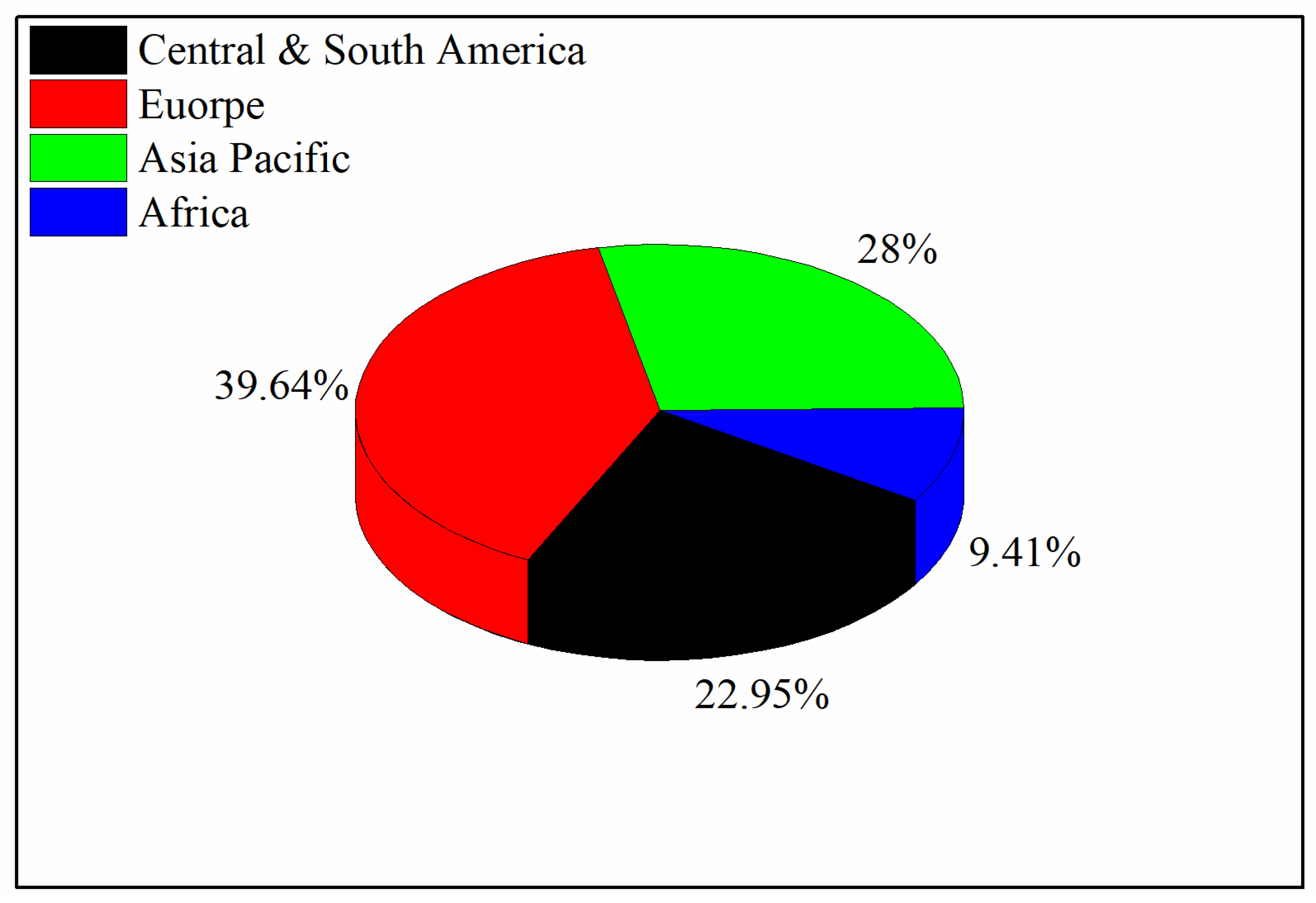
Figure 1. A comparison of the renewable energy generation of different continents [20].
Energies 17 01526 g001
Figure 2. Global power capacity generation for the last 15 years [20].
Energies 17 01526 g002
Figure 3. Types of solar collectors.
Energies 17 01526 g003
Figure 4. Flow chart of the operating parameters affecting various thermal performance parameters.
Energies 17 01526 g004
Figure 5. Effect of flow rate on thermal efficiency: (a) [30]; (b) [31]; (c) [29].
Energies 17 01526 g005
Figure 6. Heat transfer network for the V-groove double-pass solar air heater [33].
Energies 17 01526 g006
Figure 7. Effect of the flow rate on the outlet air temperature [24].
Energies 17 01526 g007
Figure 8. Effect of the mass flow rate on the pressure drop [35]—reproduced with permission from [35], Elsvier, 2021.
Energies 17 01526 g008
Figure 9. Thermal hydraulic efficiency variation with (a) mass flow rate [37]; (b) inclination angle [36].
Energies 17 01526 g009
Figure 10. Effect of the temperature rise parameter on thermal efficiency: (a) [40]; (b) [41]; (c) [42]; (d) [43].
Energies 17 01526 g010
Figure 11. Effect of the Reynold number and flow rate on the Nusselt number: (a) [44]; (b) [45]; (c) [46].
Energies 17 01526 g011
Figure 12. Effect of the Reynold number on friction factor: (a) Delta-shaped baffles [48]; (b) corrugated absorbers [49].
Energies 17 01526 g012
Figure 13. Current absorber geometry/shape used to enhance the thermal performance of SACs.
Energies 17 01526 g013
Figure 14. S-shaped rib arrangement on the collector plate fin/rib height.
Energies 17 01526 g014
Figure 15. Effect of the fin height on the thermal performance of solar air heaters (a) [54], (b) [30].
Energies 17 01526 g015
Figure 16. Effect of relative roughness pitch on the thermal efficiency reported in the literature: (a) [44]; (b) [64]; (c) [65].
Energies 17 01526 g016
Figure 17. Effect of relative roughness pitch on Nusselt number and friction factor: (a) square transverse ribs [45]; (b) triangular ribs [46].
Energies 17 01526 g017
Figure 18. Schematic of absorber with fins and baffle [69] (reproduced with permission from [69], Elsevier, 2020).
Energies 17 01526 g018
Figure 19. Solar air collector with rectangular baffles and flat-plate.
Energies 17 01526 g019
Figure 20. Schematic of perforated baffles installed on the absorber plate.
Energies 17 01526 g020
Figure 21. (a) Flat-plate SAC. (b) Wave-shaped type 1. (c) Wave-shaped type.
Energies 17 01526 g021
Figure 22. Solar air collector with plus-shaped baffles.
Energies 17 01526 g022
Figure 23. Schematic of discrete V-shaped baffles.
Energies 17 01526 g023
Figure 24. (a) Thermal efficiency and (b) outlet air temperature comparison of different absorbers with respect to the flow rate [113].
Energies 17 01526 g024
Figure 25. Schematic of V-groove punched V-rib SAHs.
Energies 17 01526 g025
Figure 26. (a) V-corrugated with twisted tape insert. (b) Twisted tape schematic.
Energies 17 01526 g026
Figure 27. Geometric parameters of triangular-shaped absorbers [137].
Energies 17 01526 g027
Figure 28. (a) Flat-plate, (b) DAS Model, (c) DAS-Rev, and (d) Z-Type [138] (reproduced with permission from [138], Elsevier, 2021).
Energies 17 01526 g028
Figure 29. Effect of flow rate on exergy efficiency: (a) [144]; (b) [147]; (c) [145]; (d) [146].
Energies 17 01526 g029
Figure 30. Effect of temperature rise parameter on exergy efficiency: (a) [148]; (b) [149]; (c) [150].
Energies 17 01526 g030
Figure 31. (a) Schematic of SPDDJP solar air heater. (b) SPSDJP solar air heater. (c) Absorber plate. (d) Jet plate [130].
Energies 17 01526 g031
Figure 32. Effect of the baffle angle on effective and exergy efficiency [151].
Energies 17 01526 g032
Figure 33. Schematic of turbulator Acır, Canlı [150] (reproduced with permission from [150], Elsevier, 2017).
Energies 17 01526 g033
Figure 34. Different absorber positions [149] (reproduced with permission from [149], Elsevier, 2006).
Energies 17 01526 g034
Figure 35. Effect of the temperature rise parameter on the entropy generation number (a) [162], (b) [163].
Energies 17 01526 g035
Figure 36. General methodology for optimizing the solar air heater patent.
Energies 17 01526 g036
Figure 37. Desiccant cooling system assisted by solar air heater [175] (reproduced with permission from [175], Elsevier, 2019).
Energies 17 01526 g037
Figure 38. Schematic of HDH for water desalination [195]—reproduced with permission from [195], Elsevier, 2019.
Energies 17 01526 g038
Figure 39. Types of thermal energy storage.
Energies 17 01526 g039
Table 1. Thermal hydraulic performance parameter for different ribs.
Ref.Ribs DesignTHPP
[72]V-rib1.46
[73]V-down ribs1.44
[74]Transverse wire ribs1.65
[75]Circular wire ribs1.66
[76]Transverse square rib1.89
[77]Transverse rectangular ribs1.44
[78]Discrete square rib1.98
[79]V-rib2.01
Table 2. Average Nusselt number and friction factor for several types of baffles compared to flat-plate collectors.
Ref.Baffle ShapeOperating Parameters RangeRemarks Compared to Flat Channel
[96]Angled R e = 9000 76,000
e D = 0.078 0.086
P e = 10 14
α = 45 ° 60 °
Nuave = 3.16 and fave = 3.56 greater than the flat-plate
[97]Angled R e = 200 1000
e H = 0.2 0.5
L 1 H = 1 2
α = 30 °
Nuave = 3.45 and fave = 3.67 greater than the flat-plate
[98]V-shaped R e = 5000 25,000
e H = 0.2 0.4
P e = 3 8
Nuave = 4.05 and fave = 4.32 greater than the flat-plate
[95]Perforated R e = 2700 11,150
e D = 0.495
β = 26 46.8 %
P e = 7.21 28.84
Nuave = 3.87 and fave = 4.12 greater than the flat-plate
[99]Transverse perforated R e = 20,000 40,000
e D = 1
W c H = 7.5
Nuave = 3.98 and fave = 4.2 greater than the flat-plate
[100]Transverse R e = 3800 18,000
e D = 0.03
P e = 10 25
Nuave = 3.45 and fave = 3.67 greater than the flat-plate
[48]Delta β = 45 °
α = 20 °
e H = 0.5
Nuave = 3.67 and fave = 3.89 greater than the flat-plate
[93]V-Shape perforated R e = 3800 19,000
e H = 0.285 0.6
P e = 2 7
α = 60 °
Nuave = 4.78 and fave = 5.12 greater than the flat-plate
[101]V-perforated-shaped block R e = 2000 20,000
e H = 0.4 1.0
P e = 4 12
α = 60 °
Nuave = 4.98 and fave = 5.09 greater than the flat-plate
[102]Multi-V-shaped R e = 4000 21,000
e H = 0.25
P e = 5 12
α = 45 °
Nuave = 6.28 and fave = 6.55 greater than the flat-plate
[103]V-Shaped R e = 100 1200
e H = 0.05 0.25
L 1 H = 1 2
A = 30 °
Nuave = 4.11 and fave = 4.39 greater than the flat-plate
[104]V-down perforated e H = 0.4 1.0
R e = 2000 20,000
P e = 4 12
β = 5 25 %
Nuave = 4.62 and fave = 4.84 greater than the flat-plate
[105]Diamond-shaped e H = 0.5 1.0
φ = 5 ° 35 °
R e = 100 600
Nuave = 3.45 and fave = 3.59 greater than the flat-plate
Table 3. Summary of the reviewed literature.
Ref.MethodAbsorberOperating ParametersThermal EfficiencyExergy EfficiencyOutlet Air Temperature
°C
Pressure Drop
[24]NumericalAluminum0.010–0.050 kg/s55% at I = 1000 W/m2K Tin = 10 °C and 0.050 kg/s Tout = 99 at I = 1000 W/m2 Tin = 10 °C and 0.010 kg/s
[25]ExperimentalTubular aluminum0.025–0.075 kg/s86% at 0.075 kg/s2.57% at 0.025 kg/s T = 28 °C at 0.025 kg/s295 Pa at 0.075 kg/s,
[27]Experimental16 steel wire mesh painted black0.011–0.032 kg/s65.8% at 3 cm height and 0.032 kg/s T = 45.3 K at 0.011 kg/s66 Pa at 3 cm height, and 0.032 kg/s
[34]ExperimentalTriangular-shaped0.026–0.095 kg/s80% at 0.06 kg/s 70 at 0.026104 Pa at 0.095 kg/s
[41]Experimentalstainless steel with black chrome (obstacles) and black-painted cooper plate0.0052 and 0.0074 kg/s82% at 0.0074 kg/s for leaf-shaped obstacles0.44% at 0.0074 kg/s T = 55.2 °C at 0.0052 kg/s for leaf-shaped baffles
[44]NumericalConical ribsRe = 4000–16,00069.8% at e/D = 0.044 and p/e = 10
[30]NumericalLongitudinal fins0.02–0.12 kg/s73% at N = 20 and H = 10 cm and 0.12 kg/s 70 at 0.02 kg/s, N = 20, and H = 10 cm
[64]ExperimentalWinglets ribs0.004–0.039 kg/s69%
[65]ExperimentalTwisted ribs0.001–0.013 m2K/W 84 %   at   p / e = 8 ,   α = 60 ° , and y/e = 3 0.8   at   p / e = 8 ,   α = 60 ° , and y/e = 3
[69]NumericalArc-shaped ribs0.01–0.08 kg/s 5.2% at 0.012 kg/s T = 60 °C at 0.01 kg/s
[89]NumericalPerforated baffle0.03–0.07 kg/s77% at 3 mm diameter, 7° angle, and 0.07 kg/s flow rate. 48 °C15.05 N/m2
[90]ExperimentalAluminum wave-shaped baffles10–50 m3/h73.8% at I = 756 W/m2 T = 69 °C
[91]Numerical and ExperimentalCopper plate with plus-shaped baffles0.009 to 0.011 kg/s84.30% T = 25 °C
[124]NumericalV-corrugated with twisted tapesRe = 3000–21,00074.42% at Re = 12,000; Y = 110% at Re = 300085 at Y = 1, N = 14, and Re = 3000750 Pa at Y = 1, N = 14 and Re = 20,000
[125]ExperimentalPerforated V-corrugated 71.85% maximum daily average0.975% maximum daily average T = 10   ° C
[165]Numerical and experimentalRectangular fins0.033 kg/s51% at 0.033 kg/s 75 °C at 0.033 kg/s
[166]ExperimentalCopper wool0.034–0.044 kg/s83% at 0.044 kg/s 60 °C at 0.035 kg/s26 Pa at 0.044 kg/s
[167]ExperimentalCopper tube with fins0.018 and 0.026 kg/s59.02% at 0.026 kg/s37.53% at 0.026 kg/s82.43 °C at 0.026 kg/s
[168]ExperimentalGalvanized iron sheet coated with longitudinal fins0.012–0.016 kg/s51.50% at 0.016 kg/s and number of fins = 5 68.10 °C at 0.016 kg/s and number of fins = 5
[169]Numerical and ExperimentalV-corrugated with triple pass0.011–0.015 kg/s76.39 at 0.015 kg/s18.95% 0.015 kg/s T = 25   ° C   at 0.011 kg/s
[170]ExperimentalAluminum cans arranged in series and parallel connections3–6.5 m/s79% for series connection at 6.5 m/s T = 68   ° C at 3 m/s for parallel SAC
[171]ExperimentalTrapezoidal0.02–0.044 kg/s74% at 0.044 kg/s 65 °C at 0.033 kg/s
[33]Numerical and ExperimentalV-groove double-pass0.021–0.061 kg/s88.50% at 0.061 kg/s5.18 average exergy efficiency at 0.041 kg/s84.95 °C at 0.021 kg/s
Table 4. Use of solar air collectors in desiccant cooling systems.
Ref.SystemResultsStudy
[175]PVT-SAHMaximum COP achieved was 19.8%.Numerical
[176]SAH with PCMA total of 75.82% electrical energy was saved using solar energy with PCM compared to an electric heater for desiccant cooling applications.Numerical
[177]PV/TPrimary energy saved by 90% using the PV/T system in desiccant cooling systems.Numerical (TRANSYS)
[178]PV/TCOP achieved was 0.85 by integrating PV/T into the conventional desiccant cooling system.TRANSYS
[179]SAHA total of 0.95 maximum COP was achieved for cooling purposes.Experimental
[180]SAHA total of 50% efficiency was achieved during the full regeneration mode.Numerical
Table 5. Summary of different dried products using solar air heaters.
Ref.ProductCollector TypeMass
(kg)
Temperature (°C)Time
(hr.)
η c o l
(%)
η d r y e r
(%)
SEC
kWh/kg
Moisture Variation
[128]BananaCorrugated single-pass441–731064.4055.30 3.566 to 0.2604 dry basis
[33]Pink lady AppleV-groove double-pass140–85.4788.5 3.01 kWh/kg82–15.85% wet basis
[181]Bitter gourdSingle-pass 642.27 7.8% final M.C
[182]Bitter gourdcorrugated with sensible storage440–51722.219.44.44 kWh/kg925 to 9% wet basis
[183]Red chiliDouble-pass with fins4032–673328135.26 kWh/kg80% to 10% wet basis
[184]BananaFlat-plate1.533.5–45.51638.35.8 Final 3.1% wet basis
[185]Green chiliSingle-pass trapezoidal0.832–721853.848.91.532 kWh/kg0.714 kg water removed
[186]Ghost chili pepper 937–574222.954.0518.72 kWh/kg85.50 to 9.7% wet basis
[187]Sewage Sludge 452.25–2.7560 14 kWh/kg
[188]TomatoAluminum cans absorber 5030 h70 19 to less than 1 d.b
[189]Stevia leavesFlat-plate 585.83 83.40–8.71%
[190]Cocoa beanSingle-pass Flat-plate8.9345032Above 30%9–1415 kWh/kg0.08 kg/kg db
[191]Potato chipsV-groove1.04605 h. 40 min 1.567 kWh/kg72 to 12%
[192]GuavaSingle-pass corrugated0.8731465.376.841.675 kWh/kg0.4574 kg/kg d.b
[193]Ivy gourdSingle-pass corrugated0.8661694.517.455.96 kWh/kg15 to 0.036 kg/kg d.b
Disclaimer/Publisher’s Note: The statements, opinions and data contained in all publications are solely those of the individual author(s) and contributor(s) and not of MDPI and/or the editor(s). MDPI and/or the editor(s) disclaim responsibility for any injury to people or property resulting from any ideas, methods, instructions or products referred to in the content.