Article

Characterization of the Macroscopic Impact of Diverse Microscale Transport Mechanisms of Gas in Micro-Nano Pores and Fractures

1
CNOOC Research Institute, Beijing 100028, China
2
School of Energy Resources, China University of Geosciences, Beijing 100083, China
*
Author to whom correspondence should be addressed.
Energies 2024, 17(5), 1145; https://doi.org/10.3390/en17051145
Submission received: 15 January 2024 / Revised: 22 February 2024 / Accepted: 25 February 2024 / Published: 28 February 2024

Abstract

:
The objective of this study is to construct a refined microscopic transport model that elucidates the transport mechanisms of gas flow within micro-nano pores and fractures. The collective impact of various microscopic transport mechanisms was explained through the apparent permeability model, specifically related to gases such as methane and carbon dioxide, within the shale matrix. The apparent permeability models, taking into account microscopic transport mechanisms such as slippage flow, Knudsen diffusion, transition flow, and surface diffusion, were established individually. Subsequently, the influencing factors on apparent permeability were analyzed. The results demonstrate that the apparent permeability of the shale reservoir matrix is significantly influenced by pore pressure, temperature, pore size, and total organic carbon (TOC). As pressure decreases, the apparent permeability of Knudsen diffusion and surface diffusion increases, while the apparent permeability of slippage flow decreases. In addition, the apparent permeability of the reservoir matrix initially decreases and then increases. With increasing temperature, the apparent permeability of slippage flow, Knudsen diffusion, and surface diffusion all increase, as does the apparent permeability of the reservoir matrix. As pore size increases, the apparent permeability of surface diffusion and Knudsen diffusion decreases, while the apparent permeability of slippage flow and the reservoir matrix increases. Furthermore, an increase in TOC leads to no change in the apparent permeability of slippage flow and Knudsen diffusion, but an increase in the apparent permeability of surface diffusion and the reservoir matrix. The model presented in this paper enhances the multi-scale characterization of gas microflow mechanisms in shale and establishes the macroscopic application of these micro-mechanisms. Moreover, this study provides a theoretical foundation for the implementation of carbon capture, utilization, and storage (CCUS) in shale gas production.

1. Introduction

The shale reservoir matrix predominantly comprises micro-nano scale pores and fractures, wherein gas manifests unique transport mechanisms relative to those observed in larger-scale pores and fractures. Consequently, the advancement of micro-transport models for gases, particularly methane and carbon dioxide, assumes paramount importance in characterizing the macroscopic influences of multiple micro-transport mechanisms. Furthermore, this endeavor can lay a solid theoretical groundwork for the successful integration of carbon capture, utilization, and storage techniques within the realm of shale gas production.
At present, predecessors have considered multi-microscopic transport mechanisms, including bulk phase gas transport (slippage effect, Knudsen diffusion, and viscous flow), surface diffusion, real gas, adsorption layer, rarefied gas, and stress sensitivity [1,2,3], to establish the microscopic transport model of shale gas. Moreover, from a macroscopic application perspective, the apparent permeability is used to characterize the microscopic transport mechanism of gas. Thereafter, a multi-scale characterization model is established [4,5], which realizes the unity of the micro-mechanism and macro model.
Previous literature has laid the foundation for the establishment of multi-scale characterization models by clarifying the multiple micro-transport mechanisms of gas in micro-nano pores and fractures of shale matrix. For the micro-transport mechanism of bulk gas, Wu et al. proposed that the flow patterns in the shale matrix include continuous flow, slippage flow, and transitional flow [6]. Zhang pointed out that throughout the entire shale gas production cycle, all flow patterns, such as continuous flow, slippage flow, transition flow, and Knudsen diffusion, can occur in the nano pores of shale, and the transport mechanisms within different pore sizes are different [2]. Among them, continuous flow can be characterized by Darcy’s law, which is widely used in conventional oil and gas reservoirs. The influence of the slippage effect can be characterized by modified permeability for slippage flow, and the modified coefficient of permeability can be obtained by fitting experimental data [7]. Knudsen diffusion is driven by pressure difference [8], which can be characterized by modifying the bulk gas permeability. Moreover, the microscopic transport mechanism of the adsorbed phase is characterized by surface diffusion [1]. The study of Sheng et al. showed that the concentration gradient was the driving force of surface diffusion, which can use the Langmuir equation and Fick’s law to establish a surface diffusion model [9]. Zhang et al. pointed out that adsorbed gas molecules migrated under the action of the adsorption potential field, which can be characterized by combining the Maxwell–Stefan method with chemical potential [2]. In addition, Yin et al. proposed that the adsorption layer reduces the space for bulk gas transport; therefore, the influence of adsorption on gas transport in micro-nano pores is significant [10]. Previous studies considered the influence of adsorption layers by modifying permeability [1]. The research of Li et al. showed that the stress sensitivity effect is the main influencing factor of matrix apparent permeability, which controls the apparent permeability of shale matrix decrease with the increase in the permeability stress sensitivity coefficient [11]. Wu et al. proposed that the real gas effect has a significant impact on gas transport in shale reservoirs with high temperatures and pressures [12]. At present, the equation of state is employed to characterize the real gas effect in micro-transport models. The study of Wu and Chen illustrated that the real gas effect improves the gas transport ability in shale, which impact increases with increasing pressure, decreasing temperature, and decreasing pore size [1].
Based on the multiple microscopic transport mechanisms of gas, previous literature has considered different effects to establish the multi-scale mathematical representation model, which was employed to study the macro effect of multiple microscopic transport mechanisms. Ertekin et al. proposed a method to describe dynamic slip during gas transport by providing a slip factor related to pressure and composition, in which the viscous flow and Fick diffusion are considered [13]. Based on this, Clarkson et al. further employed gas desorption and established a flow model [14]. Besides, Javadpour proposed an apparent permeability formula, which characterizes Knudsen diffusion based on the interaction between gas molecules and their pore walls. This method improved the Darcy formula and described gas flow in mudstone micropores, which also illustrated that the smaller the pore size and the lower the pressure and temperature conditions, the more significant the impact of Knudsen diffusion on gas transport [15]. Considering slippage flow and Knudsen diffusion, Swami and Settari further established a numerical model for adsorbed gas and dissolved gas in micro-nano pores. The results indicated that changes in the matrix’s apparent permeability should be considered in reservoir simulation [16]. Moreover, Sheng et al. established a transient capillary flow model by considering the mechanisms of intrapore diffusion, surface diffusion, viscous slippage flow, and gas desorption. Its result shows that the influence of surface diffusion increases with the decrease in pore size [9]. Li et al. established the apparent permeability model of gas by considering viscous flow, Knudsen diffusion, and surface diffusion. Their study pointed out that under the conditions of low pressure and high pressure, the influence of various factors on the apparent permeability showed different change laws [17]. Tian et al. considered slippage flow, bulk diffusion, and Knudsen diffusion by a weighted method, which is employed to study the contribution rate of each micro-transport mechanism to the total flow rate [18]. Huang et al. studied the contribution of surface diffusion, slippage flow, Knudsen diffusion, and viscous flow to the total gas flow in nano pores of shale by comprehensively considering the pore size and pressure, pore wall roughness, pore mechanics reaction, adsorption-induced expansion reaction, and influence of the adsorption layer [19]. Considering surface diffusion, effective stress, and gas adsorption, Song et al. established a gas transport model by weighted continuous flow and Knudsen diffusion to characterize the evolution mechanism of dynamic apparent permeability of the shale reservoir [20].
In summary, the previously proposed multi-scale characterization model for gas micro-transport takes into account the microscale effects and reservoir characteristics in a more comprehensive manner. However, given the diverse array of micro-transport mechanisms for gas, there is a need to enhance the gas transport model within the micro-nano pores of the shale matrix by considering factors such as temperature, pore structure, and material composition. In light of this, our study presents a novel approach that incorporates the temperature effect and the heterogeneity of micro-nano pores in the shale matrix. By integrating various phenomena including bulk phase gas transport (continuous flow, slippage flow, transition flow, and Knudsen diffusion), adsorption layer effect, surface diffusion effect, real gas effect, and stress sensitivity effect, we establish a multi-scale characterization model for gas micro-transport mechanisms in shale matrix micro-nano pores. This model not only serves as a theoretical foundation but also paves the way for the practical application of gas micro-transport mechanisms on a macroscopic scale.
The main work of this study is as follows: First, clarify the multiple microscopic transport mechanism of gas in micro-nano pores and fractures. The apparent permeability is used to realize the multi-scale characterization of the microscopic transport mechanism. The microscopic transport model of gas in micro-nano pores and fractures of the shale matrix is established. Secondly, the accuracy of the model is verified by experimental data. Finally, based on the microscopic transport model of gas proposed in this paper, the influencing factors of the macro effect of multiple microscopic transport mechanisms of gas are quantitatively analyzed.

2. Mechanism and Model

2.1. Transport Mechanism of Gas

2.1.1. Bulk Gas

Due to the size of micro-nano pores and fractures being small, the flow pattern of bulk gas in it is different from the Darcy flow. In this paper, the Knudsen number is used as the criterion for judging the flow pattern of bulk gas in the micro-nano pores and fractures. Thereafter, the correction function corrected slippage flow is weighted with Knudsen diffusion to establish a double slippage model, which can be used to characterize the continuous flow, slippage flow, transition flow, and Knudsen diffusion of methane and carbon dioxide.

Flow Pattern

The Knudsen number (Kn) is the basis for determining the flow pattern of the gas. The Kn can be calculated by Equation (1). When Kn ≤ 0.001, the flow of gas in porous media is continuous, which can be characterized by Darcy’s law. When 0.001 ˂ Kn ≤ 0.1, the slippage flow appears. Although viscous flow still dominates, the slippage effect should be characterized by the correction of Darcy’s formula by slippage theory. When 0.1 ˂ Kn ≤ 10, it is the transition flow, which is when the probability of the collision between fluid–fluid molecules is equivalent to the collision between fluid–wall molecules. At this stage, the continuous flow assumption is not valid. When Kn > 10, since the average free path of molecules is larger than the pore size, the collision between fluid molecules and the wall is dominant. Therefore, this flow stage is Knudsen diffusion.
K n = λ L
where Kn is the Knudsen number, dimensionless; λ is the average free path of the molecule, m; L is the characteristic length, which is equal to the pore diameter, m.
Considering the real gas effect, the average free path of molecules in Formula (1) can be calculated by Formula (2) [21].
λ = μ P π Z R T 2 M
where μ is the gas viscosity, Pa·s; P is the pressure, Pa; M is the relative molecular mass, kg/mol; Z is the gas compressibility factor, dimensionless; R is the gas constant, m3·Pa/(K·mol); and T is the temperature, K.

Continuous Flow

Continuous flow can be described by Darcy’s formula, which can be characterized as the following:
J c o n t i n u o u s = ρ K μ P
where Jcontinuous is the mass flux, kg/(m2·s); ρ is the gas density, kg/m3; and K is the permeability, 1015 mD.

Slippage Flow

For the slippage flow, the assumption of the continuous medium fails and the rarefied gas effect becomes apparent. Therefore, the fluid velocity at the boundary is no longer zero, which results in the slippage effect, also known as the Klinkenberg effect. In this paper, based on the Beskok–Karniadakis model, the correction function related to the Knudsen number is employed to correct the continuous flow formula. By correcting Darcy’s formula, the slippage flow in micropores and fractures is described. The correction equation can be expressed by Equation (4) as the following:
K s l i p = K o f K n
For the circular flow section of the micropore and the rectangular flow section of the microfracture, the f(Kn) correction functions are shown in Formulas (5) and (6), respectively. The characteristic lengths are pore diameter and fracture width.
f K n = 1 + 2 α K n 1 + 8 K n 1 2 b K n
f K n = 1 + α K n 1 + 6 K n 1 b K n
where α is the rarefaction coefficient, dimensionless; b is the empirical slippage coefficient; and b = −1 represents that the slippage flow is related to the flow channel and is independent of the gas type, dimensionless.
α = 128 3 π 2 1 4 b arctan 4 K n 0.4
Darcy’s formula can be written as the following:
v = K μ d P d x
Substituting Equations (4) and (5) into Equation (8), the flow rate of slippage flow in the micropore can be expressed as Equation (9) as the following:
v s l i p = K o μ 1 + 2 α K n 1 + 8 K n 1 2 b K n d P d x
For the micropore,
v = 1 8 r 2 μ d P d x
Therefore, K o = r 2 8 , and the Equation (9) can be written as the following:
v s l i p = r 2 8 μ 1 + 2 α K n 1 + 8 K n 1 2 b K n d P d x
Similarly, substituting Equations (4) and (6) into Equation (8), the flow rate of slippage flow in the microfracture can be expressed as Equation (12), as the following:
v s l i p = K o μ 1 + α K n 1 + 6 K n 1 b K n d P d x
For the microfracture,
v = 1 12 h 2 μ d P d x
Therefore, K o = h 2 12 , and the Equation (12) can be written as the following:
v s l i p = h 2 12 μ 1 + α K n 1 + 6 K n 1 b K n d P d x
In summary, the mass flux of micropores can be expressed by Equation (15). The mass flux of microfractures can be expressed by Equation (16).
J s l i p = ρ K o μ ϕ τ 1 + 2 α K n 1 + 8 K n 1 2 b K n d P d x = r 2 8 μ ϕ τ P M Z R T 1 + 2 α K n 1 + 8 K n 1 2 b K n d P d x
J s l i p = ρ K o μ ϕ τ 1 + α K n 1 + 6 K n 1 b K n d P d x = h 2 12 μ ϕ τ P M Z R T 1 + α K n 1 + 6 K n 1 b K n d P d x
where Jslip is the slippage flux, kg/(m2·s); ϕ is porosity, dimensionless; and τ is tortuosity, dimensionless.

Knudsen Diffusion

For Knudsen diffusion, the average free path of gas molecules is much larger than the pore size. The collision of gas–wall molecules is dominant and the collision of gas–gas molecules can be ignored. Therefore, Knudsen diffusion has a constant diffusion coefficient, which can neglect viscosity effects [22]. Knudsen diffusion can be characterized by Equation (17).
q ρ ϕ A M = D k Δ P R T L
where q is the flow rate, m3/s; A is the overcurrent area, m2; and Dk is the Knudsen diffusion coefficient, m2/s.
The Knudsen diffusion coefficient can be expressed by Equation (18).
D k = d 3 8 R T π M
where d is the pore diameter, m.
Considering the average velocity of real gas molecules, u ¯ = 8 Z R T π M , thus, the Knudsen diffusion coefficient can be expressed by Equation (19).
D k = d 3 8 Z R T π M
Substitute Equation (19) into Equation (17), and the mass flux of the Knudsen diffusion can be obtained.
J K n u d s e n = q A ρ = M D k R T d P d x = d 3 8 Z M π R T d P d x = 2 3 r 8 Z M π R T d P d x
where JKnudsen is the Knudsen diffusion mass flux of the real gas, kg/(m2·s).
In the condition of the relatively rough pore wall, the Knudsen diffusion is slowed down due to the longer time that the gas stays near the pore wall. Therefore, the influence of pore wall roughness on Knudsen diffusion needs to be considered [19]. The geometric shape of pores in porous media is complex, and pores are connected to each other [23,24,25]. Moreover, the actual path of gas transmission is longer than the direct path (tortuosity), and the ratio of porosity and tortuosity should be used to correct the Knudsen diffusion coefficient [26]. Therefore, the mass flux of Knudsen diffusion can be written as:
J K n u d s e n = d 3 ϕ τ δ D f 2 8 Z M π R T d P d x = 2 3 r ϕ τ δ D f 2 8 Z M π R T d P d x
where δ is the ratio of molecular diameter to local pore diameter, dimensionless; and Df is the fractal dimension of pore wall, dimensionless.

Transition Flow

Transition flow is the transition flow state between slippage flow and Knudsen diffusion. This paper combined slippage flow with Knudsen diffusion by weight coefficients to characterize the transition flow, as shown in Equation (22).
J T r a n s = ω K n u d s e n J K n u d s e n + ω S l i p J S l i p
where ωKnudsen is the Knudsen diffusion weight coefficient, dimensionless; ωSlip is the weight coefficient of slippage flow, dimensionless; and JTrans is the mass flux of the real gas transition flow, kg/(m2·s).
Previous scholars have proposed multiple weight coefficient formulas through derivation or fitting [8,27,28]. This study uses the corrected model from Shi et al. [28] to calculate the weight coefficients.
ω s l i p = 1 1 + K n / K n 0.5 n 1
ω K n u d s e n = 1 ω s l i p
where Kn0.5 is a constant, taken as 1.03; and n is a constant, taken as 3.689.

2.1.2. Adsorption Gas

The adsorbed state is one of the important occurrence states of gas in micro-nano pores of the shale matrix. When gas is adsorbed on the pore wall, the gas molecules in the adsorption layer migrate under the action of the adsorption potential field, which is surface diffusion [19]. In this paper, the Maxwell–Stefan method is used to characterize surface diffusion. This method assumes that the driving force of surface diffusion is the chemical potential gradient, and its surface diffusion flux can be written as the following:
J s u r f a c e = L m C s ψ
The parameters in Equation (25) can be calculated by the following equations:
L m = D s R T
ψ = ψ o + R T ln P
C s = 4 M θ π d m 3 N A
where Jsurface is the surface diffusion mass flux, kg/(m2·s); Lm is the gas flow fluidity, mol·s/kg; Cs is the concentration of adsorbed gas, kg/m3; ψ is chemical potential, J/mol; Ds is the surface diffusion coefficient, m2/s; dm is the diameter of the gas molecule, m; and NA is the Avogadro constant, mol−1.
Substitute Equations (26)–(28) into Equation (25), and the surface diffusion flux can be obtained and expressed as Equation (29).
J s u r f a c e = D s C s c P d P d x
The surface diffusion coefficient in Equation (29) can be calculated by Equation (30). The parameters can be calculated by Equations (31)–(33), respectively.
D s = D s o 1 θ + κ 2 θ 2 θ + H 1 κ 1 κ κ 2 θ 2 1 θ + κ 2 θ 2
D s o = 8.29 × 10 7 T 0.5 exp Δ H 0.8 R T
H 1 κ = 0 , 1 , κ 1 0 κ < 1
κ = κ b κ m
where H(1 − κ) is the Heaviside function, dimensionless; κ is the blocking coefficient of gas molecules on the pore wall, dimensionless; κb is the blocking velocity coefficient of gas molecules on the pore wall, m/s; κm is the forward velocity coefficient of gas molecules on the pore wall, m/s; Dso is the surface diffusion coefficient with gas coverage of “0”, m2/s; and ΔH is the isothermal adsorption heat of surface coverage rate θ = 0, J/mol.

2.2. Changing Mechanism of Reservoir

During the development of shale reservoirs, there is stress sensitivity, matrix shrinkage effects, and adsorption layer, which make the size of matrix pores change with pressure [19].

2.2.1. Stress Sensitive Effect

Shale reservoir has strong stress sensitivity. With the decrease in reservoir pressure, the effective stress of the formation gradually increases. Its macro performance is the reduction of matrix permeability and porosity. This research employed exponential formulas to describe the stress sensitivity of permeability and porosity [29].
K = K o exp 3 c p P P o
ϕ = ϕ o exp c p P P o
where Ko is the initial absolute permeability, mD; Po is the initial pressure, Pa; cp is the pore compression coefficient, Pa−1; and ϕo is the initial porosity, dimensionless.
The relationship between porosity, permeability, tortuosity, and pore radius is obtained from Carman–Kozeny formula, which can be expressed as Equation (36).
r = 2 2 τ K ϕ
Substitute Equations (34) and (35) into Equation (36), and Equation (37) can be calculated, which is used to characterize the relationship between reservoir pressure and pore radius.
r = r o exp 2 c p P P o
where ro is the initial pore throat radius, m.

2.2.2. Matrix Shrinkage Effect

As the pressure of the shale reservoir decreases, the gas in the matrix pores will undergo desorption and be released. The matrix contracts due to the pressure decrease in the pore. Therefore, the volume of microfractures is increasing, which results in the apparent permeability of the matrix increasing. Moreover, previous studies show that matrix shrinkage has a significant impact on reservoir permeability [30,31]. This paper uses the formula proposed by Wang et al. to characterize the matrix shrinkage effect [32].
ω s w e l l i n g = K K o = 1 3 ϕ o ε L P L P P o P + P L P o + P L 3
where ωswelling is the matrix shrinkage coefficient, dimensionless; ɛL is Langmuir strain, dimensionless; and PL is the Langmuir pressure, Pa.

2.2.3. Effect of Adsorption Layer

Due to the adsorption gas in the shale matrix occupying the pore space, the effective pore size for bulk gas transport is reduced. As the pressure of shale reservoirs decreases, gas gradually desorbs, and the effective pore size for gas transmission increases [33]. Therefore, the transport of gas in matrix pores is affected by gas adsorption and desorption. This paper considers the thickness of one methane molecule as the maximum adsorption layer thickness. The ratio of adsorption to maximum adsorption is set as the coverage, to approximately calculate the pore size of shale matrix under the influence of the adsorption layer. For micropores and microfractures, the effective pore size and fracture width are expressed as Equation (41) and Equation (42), respectively.
θ = N N L
r a d = d m θ
r e = r d m θ
h e = h 2 d m θ
where θ is the coverage of adsorbed gas, dimensionless; N is the adsorption amount, mmol/g; NL is the maximum adsorption amount, mmol/g; rad is the thickness of the adsorption layer, m; dm is the diameter of methane molecules, m; re is the effective radius of the pore, m; and he is the effective width of the fracture, m.

2.3. Transport Model of Gas

This article employed the apparent permeability model to characterize the mass flux model with multiple transmission mechanisms. The relationship between permeability and mass flux can be expressed in Equation (43).
K = J μ Z R T M P d P d x
For slippage flow, the apparent permeability model in the micropore can be obtained from Equations (15) and (43). The apparent permeability model in the microfracture can be obtained from Equations (16) and (43). Therefore, the apparent permeability models of micropore and microfracture are expressed as Equation (44) and Equation (45), respectively.
K s l i p = r 2 8 ϕ τ 1 + 2 α K n 1 + 8 K n 1 2 b K n
K s l i p = h 2 12 ϕ τ 1 + α K n 1 + 6 K n 1 b K n
For Knudsen diffusion, the apparent permeability model obtained from Equations (20) and (43) is expressed as follows:
K K n u d s e n = d 3 ϕ τ δ D f 2 μ P 8 Z R T π M
For surface diffusion, according to Equations (29) and (43), the apparent permeability model of surface diffusion is written in Equation (47) as the following:
K s u r f a c e = D s C s c P ϕ τ μ Z R T P M
Based on the above models, apparent permeability models for micropores and microfractures in shale reservoirs are established, respectively. For organic micropores, the transport of bulk gas and adsorption gas is considered, and apparent permeability is expressed by Equation (48). In inorganic micropores, bulk gas transport is considered only. Thus, its apparent permeability is expressed as Equation (49).
K p o r e o r g a n i c = ω s l i p K s l i p + ω K n u d s e n K K n u d s e n + K s u r f a c e = ω s l i p r 2 8 ϕ τ 1 + 2 α K n 1 + 8 K n 1 2 b K n + ω K n u d s e n 2 3 r ϕ τ δ D f 2 μ P 8 Z R T π M + D s C s c P ϕ τ μ ρ g
K p o r e i n o r g a n i c = ω s l i p K s l i p + ω K n u d s e n K K n u d s e n = ω s l i p r 2 8 ϕ τ 1 + 2 α K n 1 + 8 K n 1 2 b K n + ω K n u d s e n 2 3 r ϕ τ δ D f 2 μ P 8 Z R T π M
For microfractures, the transport of bulk gas and adsorption gas is considered to set up the apparent permeability model in organic microfractures. This can be taken to be represented by Equation (50). However, in inorganic microfractures, bulk gas transport is considered, and the apparent permeability model is expressed in Equation (51).
K f r a c t u r e o r g a n i c = ω s l i p K s l i p + ω K n u d s e n K K n u d s e n = ω s l i p h 2 12 ϕ τ 1 + α K n 1 + 6 K n 1 b K n + ω K n u d s e n 2 3 h ϕ τ δ D f 2 μ P 8 Z R T π M + D s C s c P ϕ τ μ ρ g
K f r a c t u r e i n o r g a n i c = ω s l i p K s l i p + ω K n u d s e n K K n u d s e n = ω s l i p h 2 12 ϕ τ 1 + α K n 1 + 6 K n 1 b K n + ω K n u d s e n 2 3 h ϕ τ δ D f 2 μ P 8 Z R T π M
This paper takes the proportion of micropores and microfractures in the organic and inorganic matter to the total volume of pores and fractures as the weight coefficient. Meanwhile, considering the matrix shrinkage effect, the apparent permeability model of the shale reservoir matrix is established.
K a p p = γ α K p o r e o r g a n i c + 1 α K p o r e i n o r g a n i c + 1 γ β K f r a c t u r e o r g a n i c + 1 β K f r a c t u r e i n o r g a n i c ω s w e l l i n g
where α is the proportion of organic matter pore volume to total pore volume, dimensionless; β is the proportion of organic matter fracture volume to total fracture volume, dimensionless; and γ is the proportion of pore volume to total pore volume, dimensionless.

3. Model Validation

To verify the accuracy of the apparent permeability model of the shale matrix established in this paper, experimental data from Shi et al. [34] were used to validate the model. The fitting parameters used for validation are shown in Table 1, and the other basic parameters are shown in Table 2.
As the results show in Figure 1, the variation pattern of matrix apparent permeability with pressure described by this model is consistent with the experimental results. Therefore, the shale matrix apparent permeability model established in this paper based on the multiple microscopic transmission mechanisms can be used to characterize the multiple transmission mechanisms of shale gas. Moreover, the change rule of reservoir matrix permeability can be studied by this model, which has practicability.

4. Analysis and Discussion

4.1. Influence for Knudsen Number

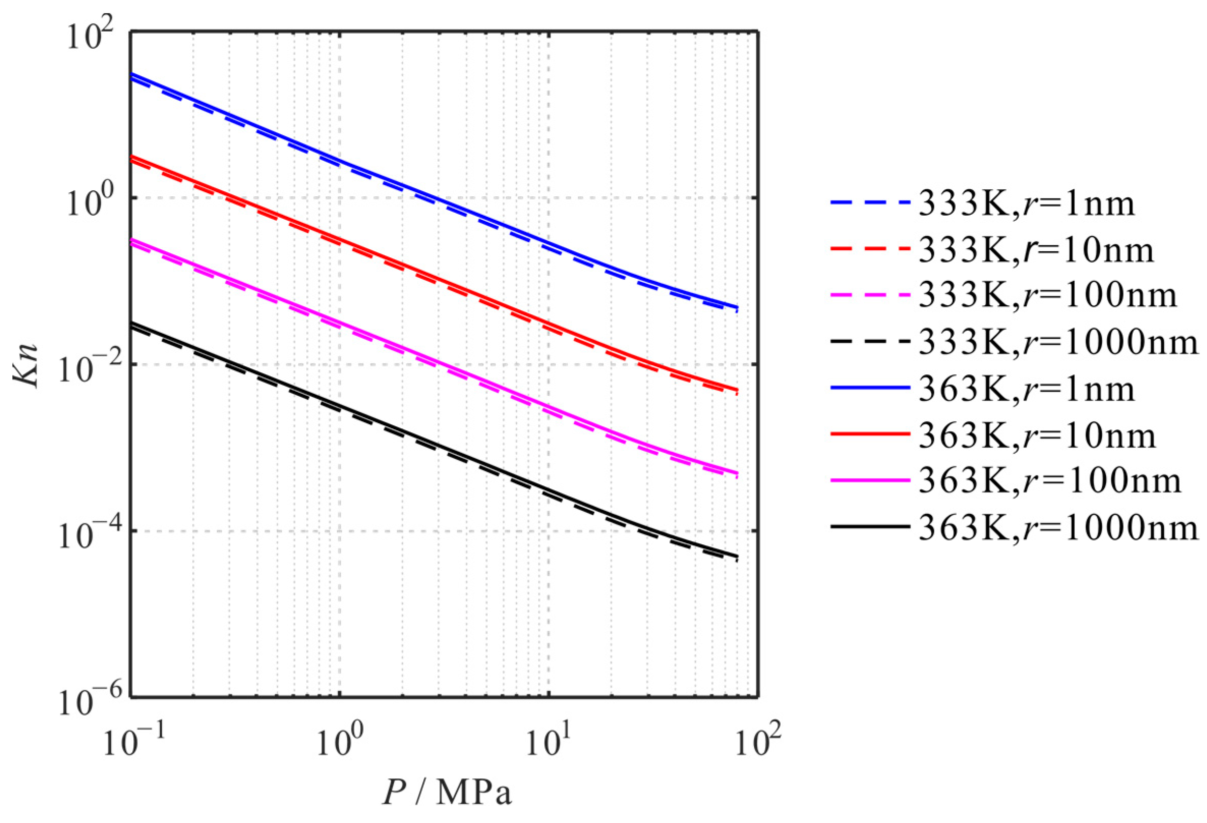
According to the general conditions of shale gas reservoirs, the pressure and pore size distribution ranges are 1~50 MPa and 2~1000 nm, respectively [1]. This paper calculates the Knudsen numbers with pore sizes of 1 nm, 10 nm, 100 nm, and 1000 nm at temperatures of 333 K and 363 K, with pressures of 0.1 MPa to 80 MPa, respectively, as shown in Figure 2. It can be seen that during the development of the shale gas reservoir, the flow pattern of shale gas can include all the flow patterns from Knudsen diffusion to continuous flow. Moreover, as the aperture increases, the Knudsen number decreases. As the pressure increases, the Knudsen number decreases. As the temperature increases, the Knudsen number increases (see Figure 2).
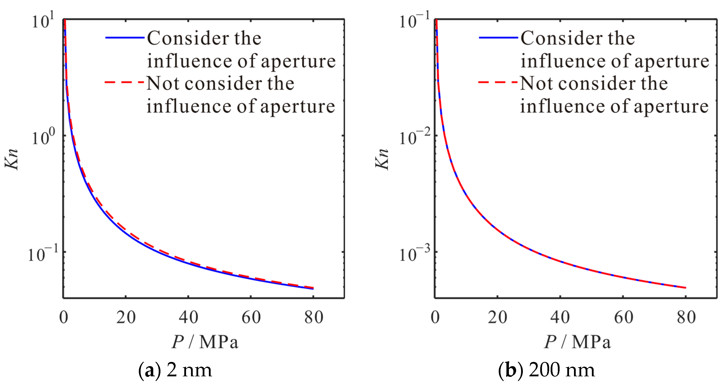
Considering the real gas effect in the micro-nano pores of the shale, the influence of micro-nano pores on the physical properties of methane is characterized by the compressibility factor in Equation (2). As shown in Figure 3, considering the compressibility factor, the Knudsen number decreases. In small apertures, the decrease in the Knudsen number is more pronounced.

4.2. Influence of Pressure

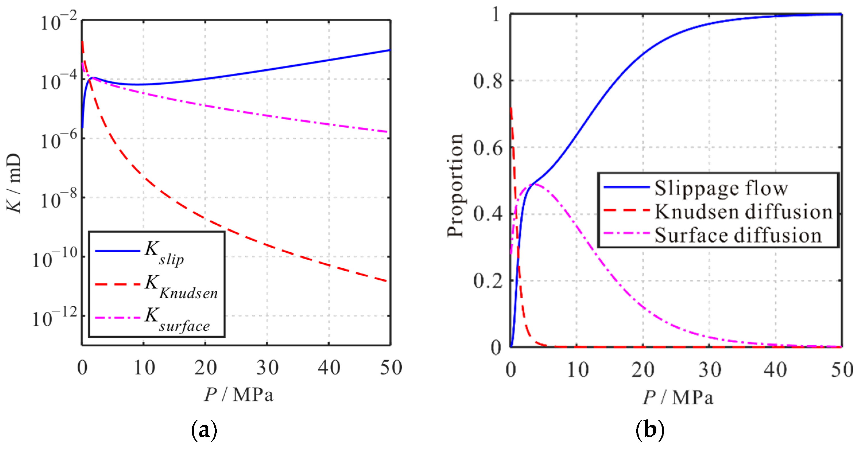
Under the same conditions, using pressure as a variable, the micro-transport mechanisms and the changes in matrix apparent permeability are studied. As shown in Figure 4a, with pressure decreasing from 50 MPa to 0 MPa, the apparent permeability of the surface diffusion and the Knudsen diffusion increases by two and eight orders of magnitude, respectively. However, the apparent permeability of slippage flow decreases by two orders of magnitude. Thereafter, the contributions of the three transport mechanisms to the apparent permeability of the shale matrix are analyzed (see Figure 4b). As the pressure decreases from 50 MPa to 0 MPa, the contribution proportion of slippage flow decreases from 1 to 0. The contribution proportion of Knudsen diffusion increases from 0 to 0.72. The contribution proportion of surface diffusion increases first and then decreases, with the largest contribution proportion at 3.6 MPa, 0.49. Moreover, when the pressure is low, the changing of the contribution proportion for the three transport mechanisms to the apparent permeability can be seen more significantly. It can be seen that pressure changes have a significant impact on the values and contribution proportions of the apparent permeability of the three transmission mechanisms.
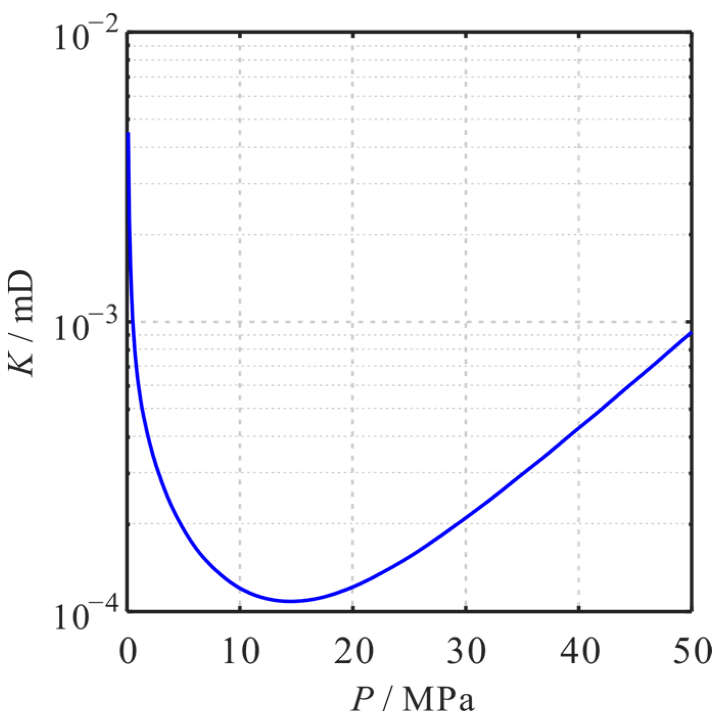
As shown in Figure 5, as pressure decreases, the apparent permeability of the matrix shows a trend of first decreasing and then increasing. Its value varies from 9.2 × 10⁻⁴ mD at the initial 50 MPa, reduced to 1.1 × 10⁻⁴ mD at 14.5 MPa. Then, values rise to 4.5 × 10⁻³ mD at 0 MPa. Based on the relationship between the transport mechanism, the apparent permeability, and pressure, it can be concluded that as pressure decreases, the apparent permeability of the matrix decreases, since the apparent permeability of the slippage flow decreases. With the further decrease in pressure, the apparent permeability of the shale matrix increases due to the increase in apparent permeability contributed by Knudsen diffusion and surface diffusion.

4.3. Influence of Temperature

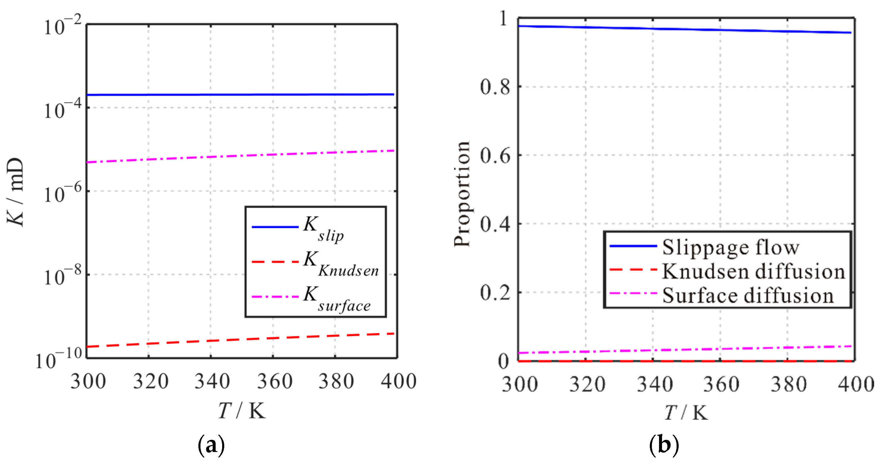
Under the same conditions, using temperature as a variable, the micro-transport mechanisms and the changes in matrix apparent permeability are studied. As shown in Figure 6a, with the temperature increase from 300 K to 400 K, the apparent permeability of the slippage flow, surface diffusion, and the Knudsen diffusion increase by 2.49%, 106.92%, and 89.78%, respectively. Thereafter, the contributions of the three transport mechanisms to the apparent permeability of the shale matrix are analyzed (see Figure 6b). As the temperature increases from 300 K to 400 K, the contribution proportion of slippage flow decreases from 0.98 to 0.96. The contribution proportion of surface diffusion increases from 0.02 to 0.04. The contribution proportion of Knudsen diffusion is small, although it increases. It can be seen that temperature changes have a significant impact on the values of the apparent permeability of the three transmission mechanisms. The impact on the contribution proportions of the apparent permeability is small.
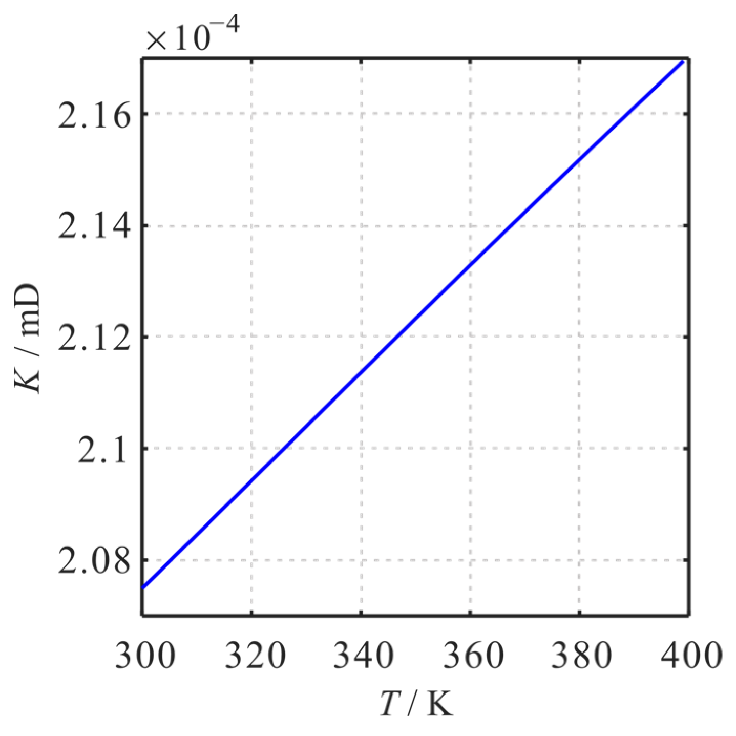
As shown in Figure 7, as temperature increases, the apparent permeability of the matrix increases. Its value varies from 2.075 × 10⁻⁴ mD at the initial 300 K, raised to 2.170 × 10⁻⁴ mD at 400 K. Based on the relationship between the transport mechanism, the apparent permeability, and temperature, it can be concluded that as temperature increases, the apparent permeability of the matrix increases. It is because the apparent permeability of slippage flow, Knudsen diffusion, and surface diffusion all increase.

4.4. Influence of Pore Size

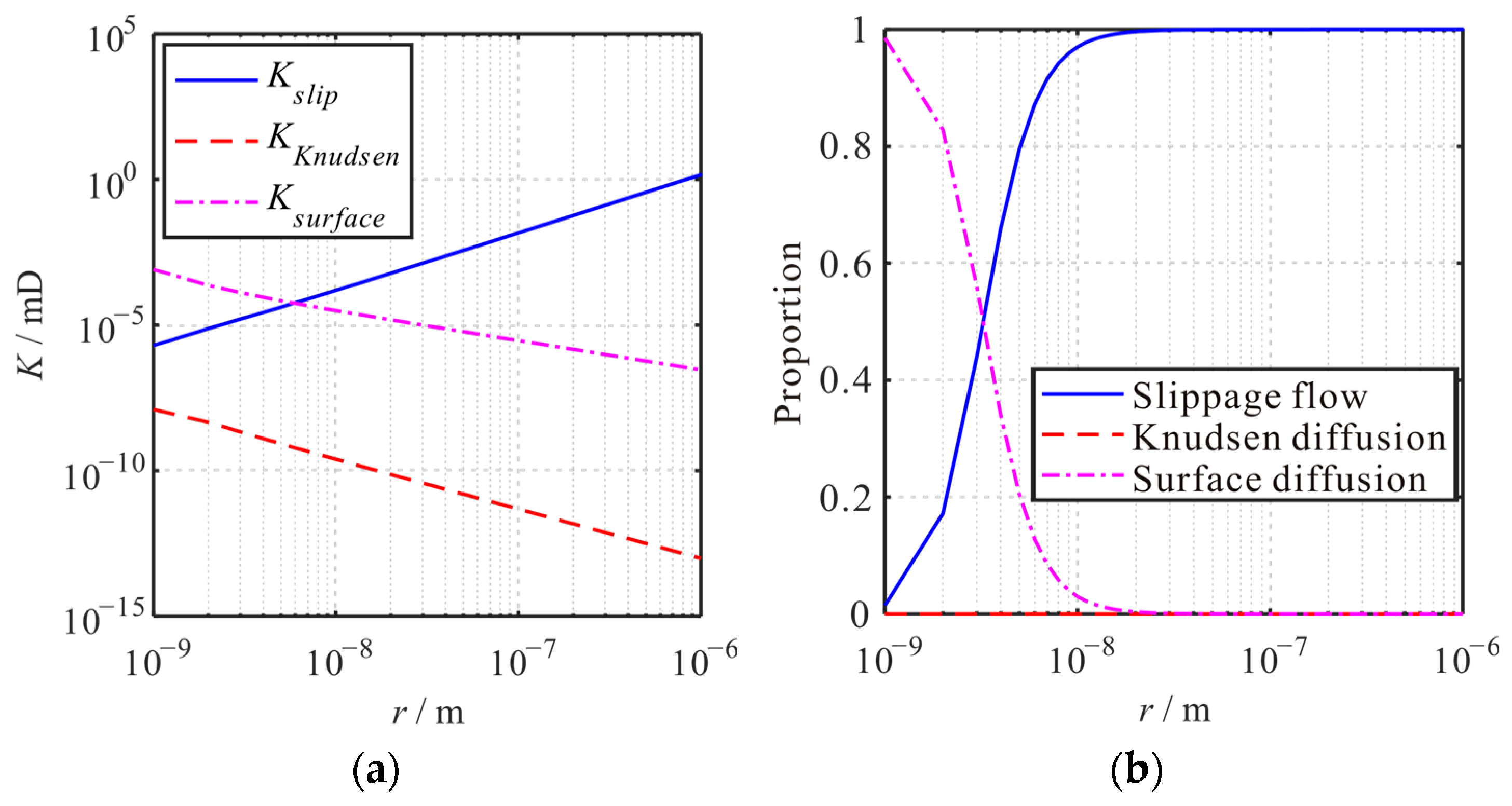
Under the same conditions, using pore size as a variable, the micro-transport mechanisms and the changes in matrix apparent permeability are studied. As shown in Figure 8a, with pore size increasing from 1 × 10⁻⁹ m to 1 × 10⁻⁶ m, the apparent permeability of the surface diffusion and the Knudsen diffusion decreases by three and six orders of magnitude, respectively. However, the apparent permeability of slippage flow increases by six orders of magnitude. Thereafter, the contributions of the three transport mechanisms to the apparent permeability of the shale matrix are analyzed (see Figure 8b). As the pore size increases from 1 × 10⁻⁹ m to 1 × 10⁻⁶ m, the contribution proportion of slippage flow increases from 0.015 to 1. The contribution proportion of surface diffusion decreases from 0.985 to 0. The contribution proportion of Knudsen diffusion increases first and then decreases, although it is small. It can be seen that pore size changes have a significant impact on the values and contribution proportions of the apparent permeability of the three transmission mechanisms.
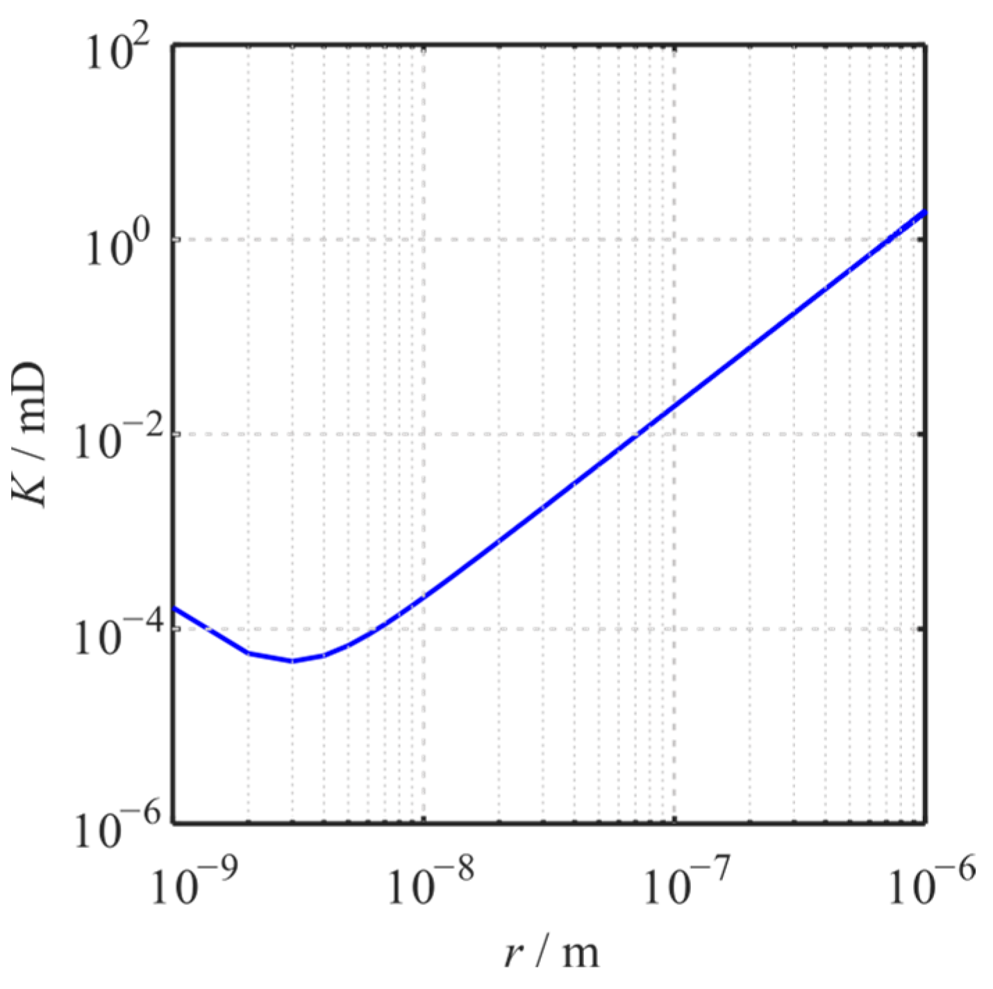
As shown in Figure 9, as pore size increases, the apparent permeability of the matrix shows a trend of first decreasing and then increasing. Its value varies from 1.66 × 10⁻⁴ mD at the initial 1 × 10⁻⁹ m, reduced to 1.90 × 10⁻⁴ mD at 1 × 10⁻⁶ m. Based on the relationship between the transport mechanism, the apparent permeability, and pore size, it can be concluded that as pore size increases from 1 nm to 3 nm, the apparent permeability of the matrix decreases, since the apparent permeability of the surface diffusion decreases. With the further increase in pore size, the apparent permeability of the shale matrix increases due to the increase in apparent permeability contributed by slippage flow.

4.5. Influence of Tortuosity

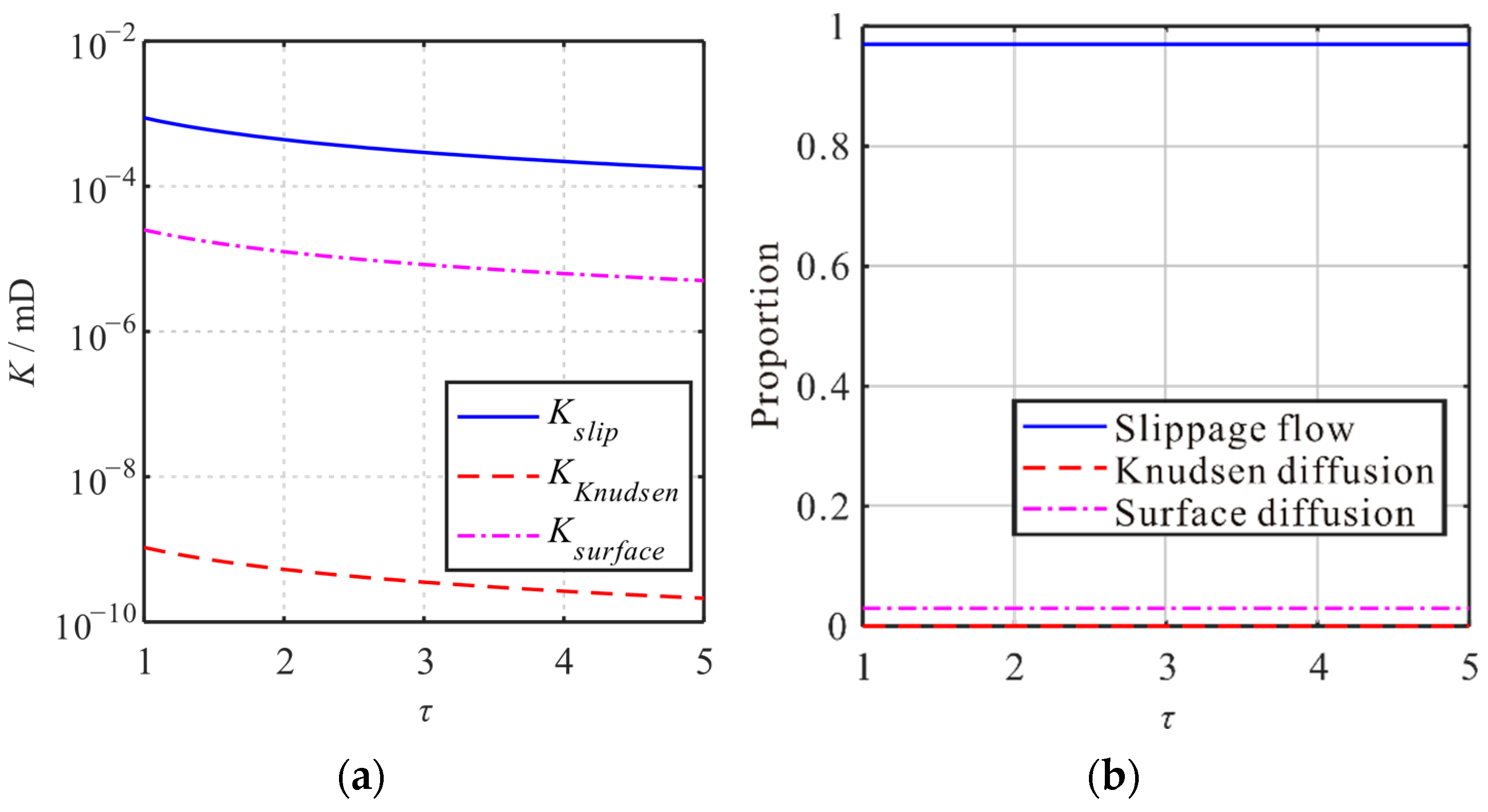
Under the same conditions, using tortuosity as a variable, the micro-transport mechanisms and the changes in matrix apparent permeability are studied. As shown in Figure 10a, with tortuosity increasing from one to five, the apparent permeability of the slippage flow, surface diffusion, and Knudsen diffusion decrease by 80%, respectively. Thereafter, the contributions of the three transport mechanisms to the apparent permeability of the shale matrix are analyzed (see Figure 10b). As the tortuosity increases from one to five, the contribution proportions of slippage flow, surface diffusion, and Knudsen diffusion are maintained at 0.97, 0.03, and 0, respectively. It can be seen that tortuosity changes have a significant impact on the values of the apparent permeability of the three transmission mechanisms. However, the tortuosity change has no impact on the contribution proportions of the three transmission mechanisms.
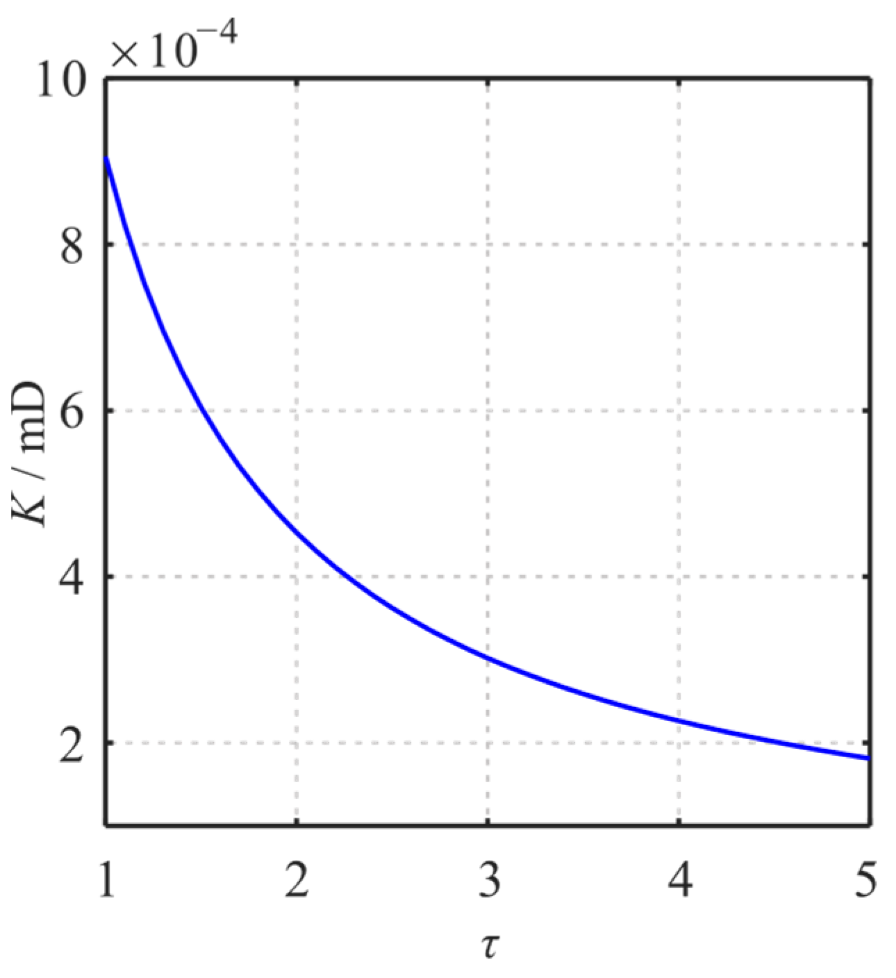
As shown in Figure 11, as tortuosity increases, the apparent permeability of the matrix shows a trend of increasing. Its value varies from 9.06 × 10⁻⁴ mD at the initial τ = 1, reduced to 1.81 × 10⁻⁴ mD at τ = 5. Based on the relationship between the transport mechanism, the apparent permeability, and tortuosity, it can be concluded that as tortuosity increases, the apparent permeability of the matrix decreases, since the apparent permeability of the slippage flow, surface diffusion, and Knudsen diffusion all decrease. Moreover, the contribution proportion of three micro-transport mechanisms to the apparent permeability is invariant.

4.6. Influence of Total Organic Carbon (TOC)

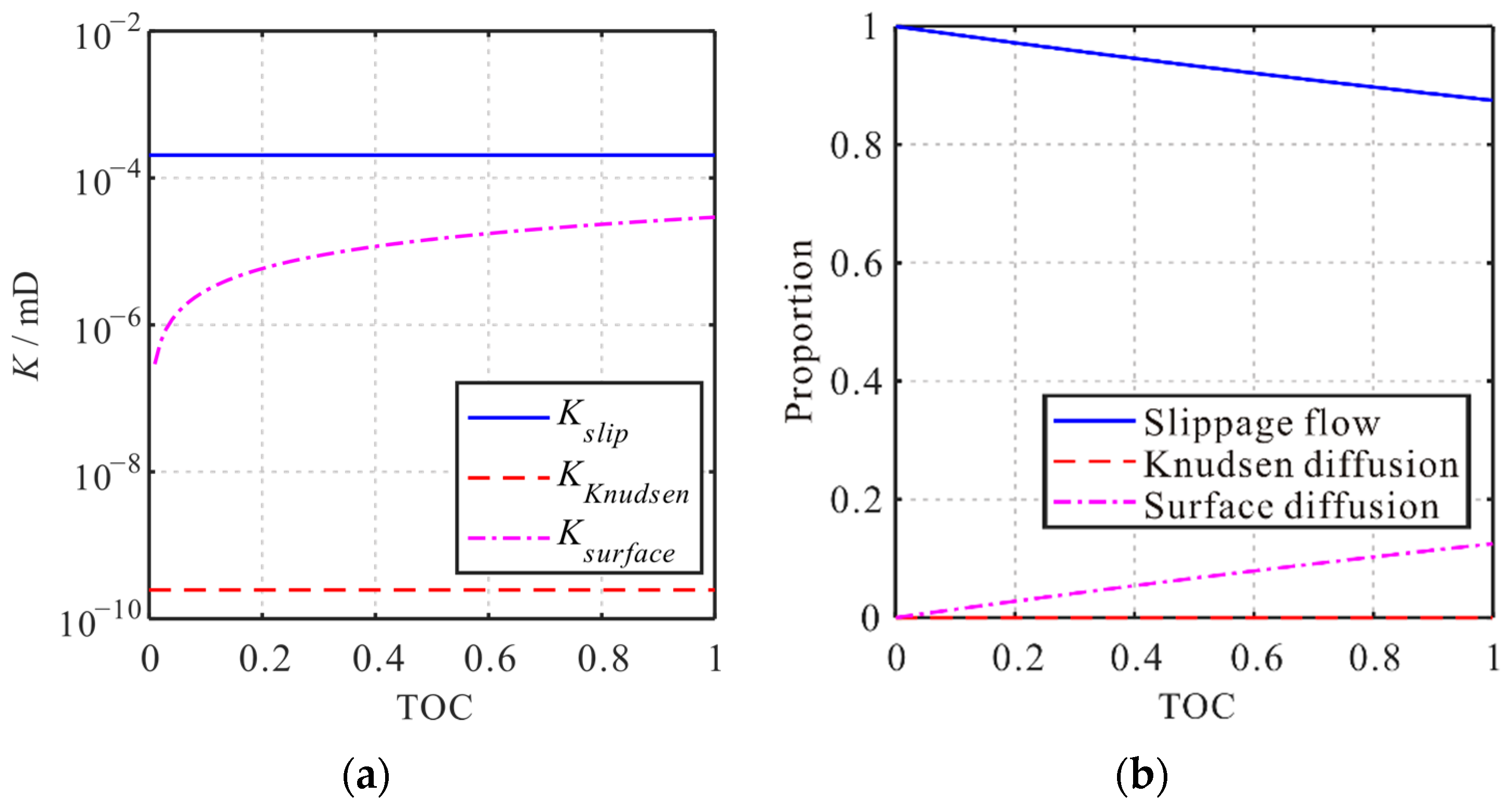
Under the same conditions, using TOC as a variable, the micro-transport mechanisms and the changes in matrix apparent permeability are studied. As shown in Figure 12a, with TOC increasing from zero to one, the apparent permeability of the slippage flow and the Knudsen diffusion is unchanged. The apparent permeability of the surface diffusion is increasing. Thereafter, the contributions of the three transport mechanisms to the apparent permeability of the shale matrix are analyzed (see Figure 12b). As the TOC increases from zero to one, the contribution proportions of slippage flow are reduced from 1 to 0.875. The contribution proportions of surface diffusion increased from 0 to 0.125. However, as the TOC increases, the contribution proportions of the Knudsen diffusion decrease gradually, which are always small.
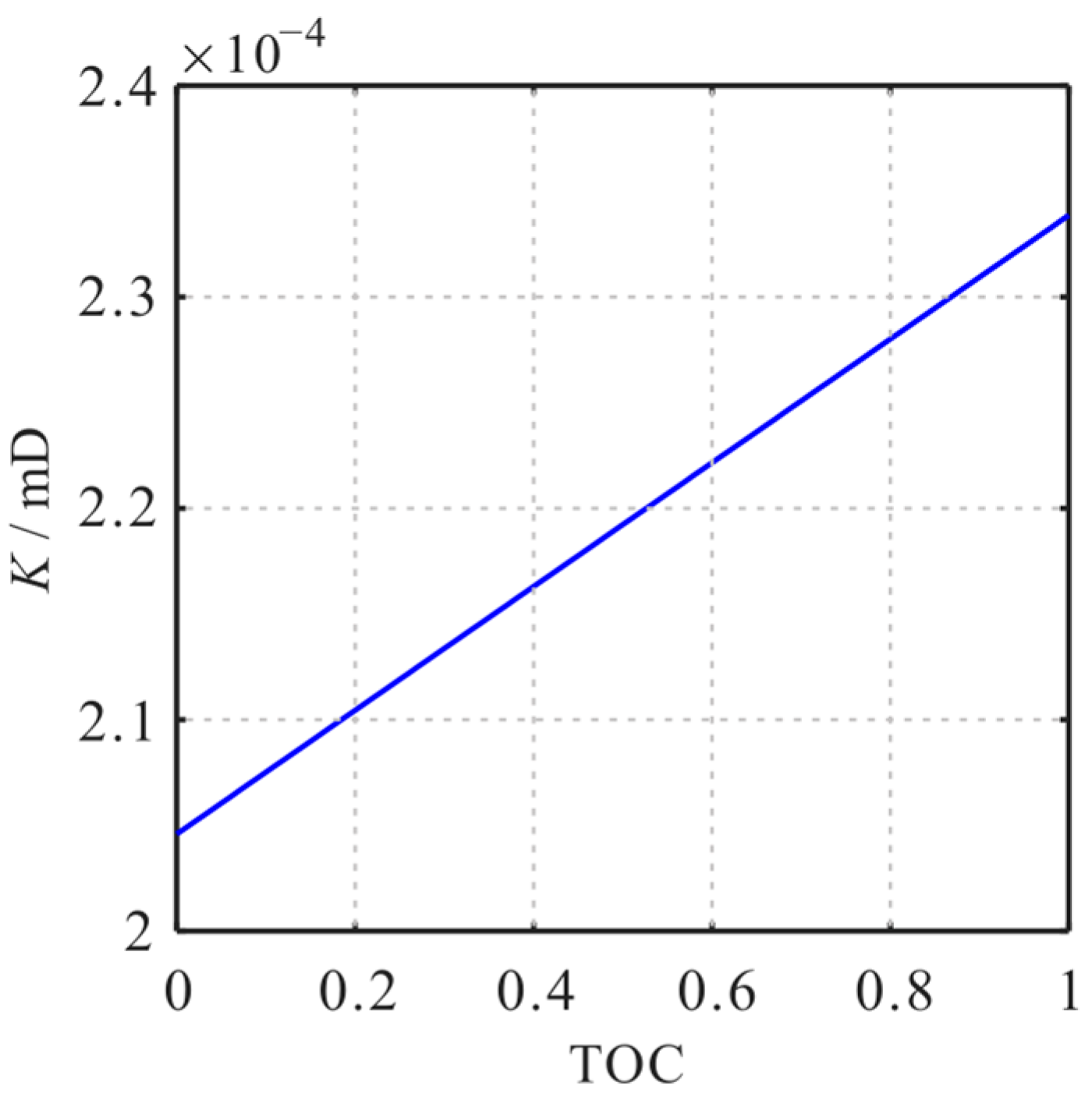
As shown in Figure 13, as TOC increases, the apparent permeability of the matrix increases. Its value varies from 2.05 × 10⁻⁴ mD at the TOC = 0, raised to 2.34 × 10⁻⁴ mD at the TOC = 1. Based on the relationship between the transport mechanism, the apparent permeability, and TOC, it can be concluded that as TOC increases, the apparent permeability of the matrix increases. It is because the apparent permeability of surface diffusion increases.

4.7. Combined Influence

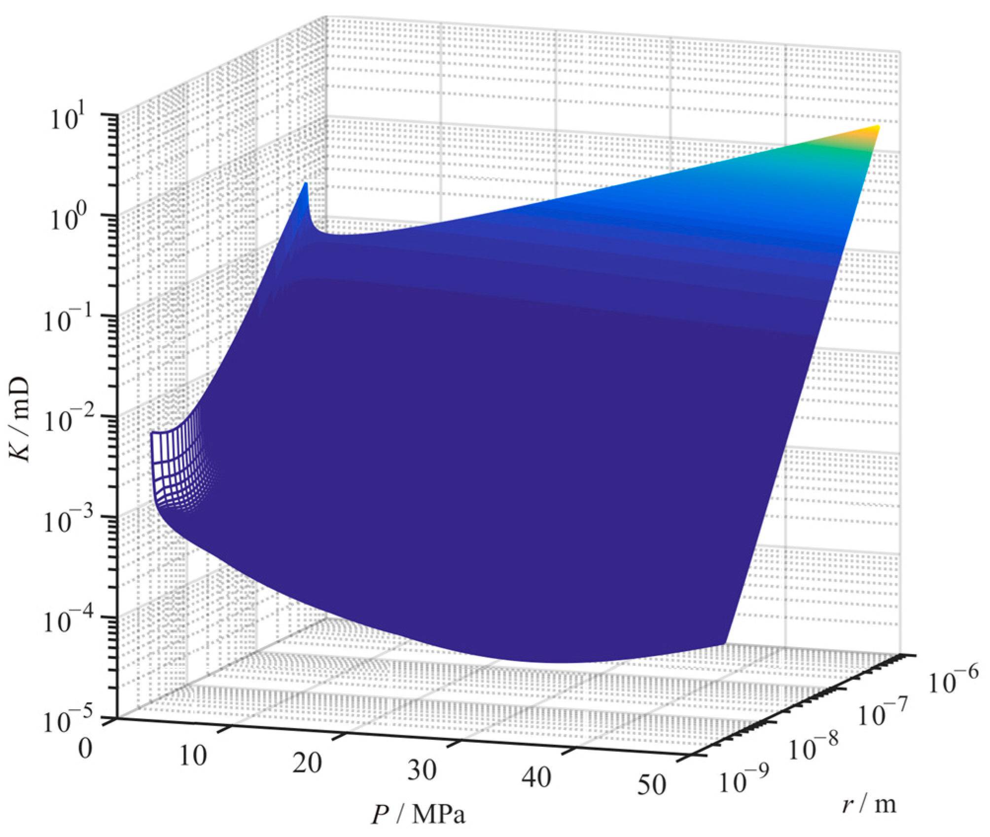
Considering the actual situation of the comprehensive action of multiple factors in the development of shale gas, the microscopic transport mechanism, the variation law of matrix apparent permeability in different pore sizes under different temperatures, and pressure conditions are analyzed.
As Figure 14 shows, the larger the pore size, the larger the apparent permeability of the shale matrix under the condition of constant temperature. With the decrease in pressure, the apparent permeability of the shale matrix with different pore sizes decreases first and then increases. With the increase in temperature, the apparent permeability of the matrix increases, and its variation amplitude increases with the decrease in pore size and pressure (see Figure 15).
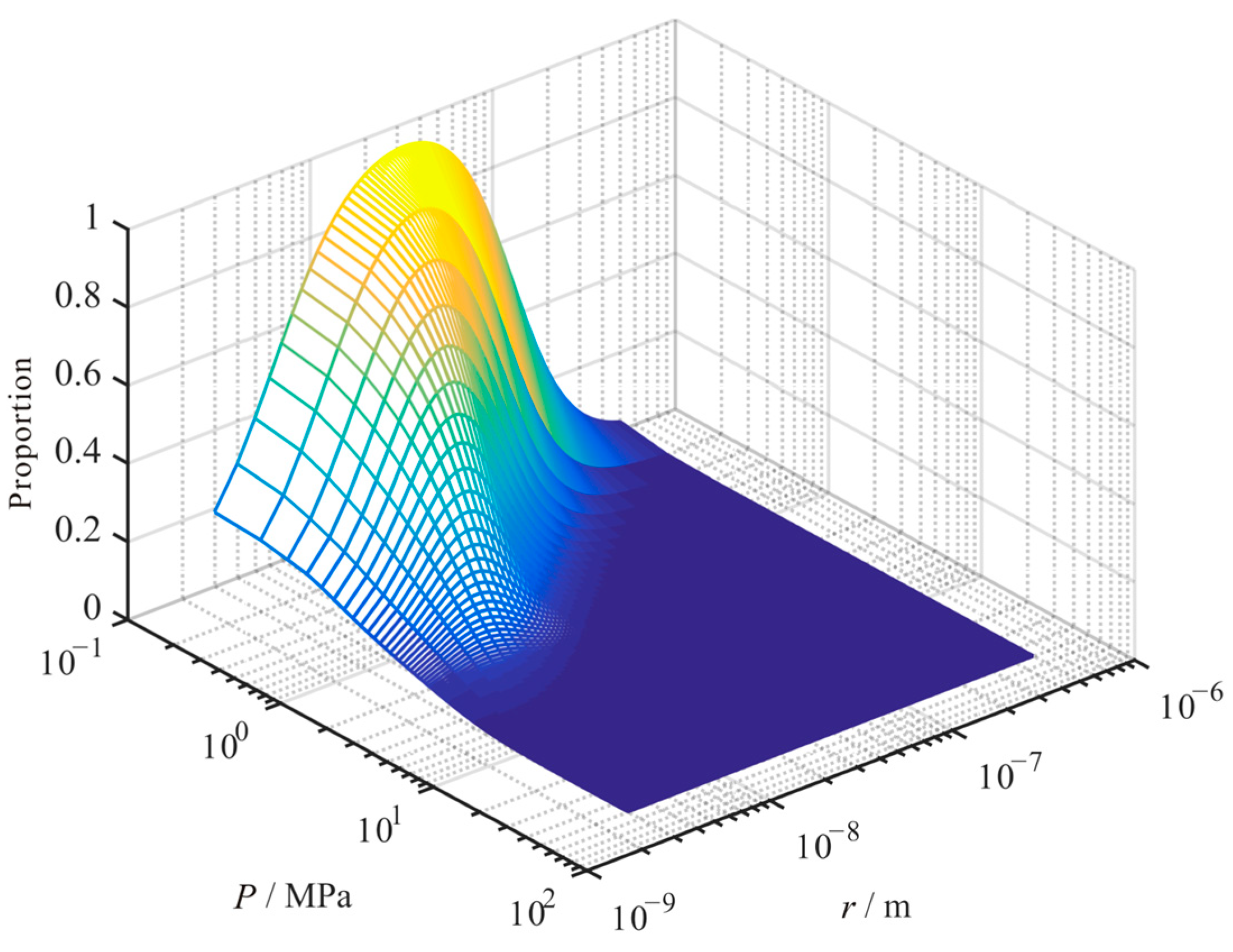
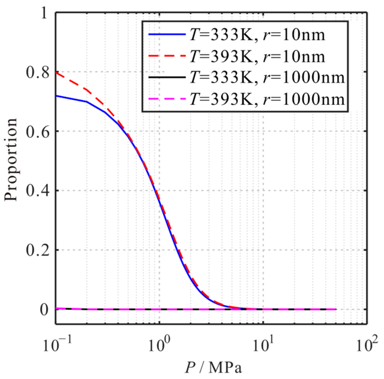
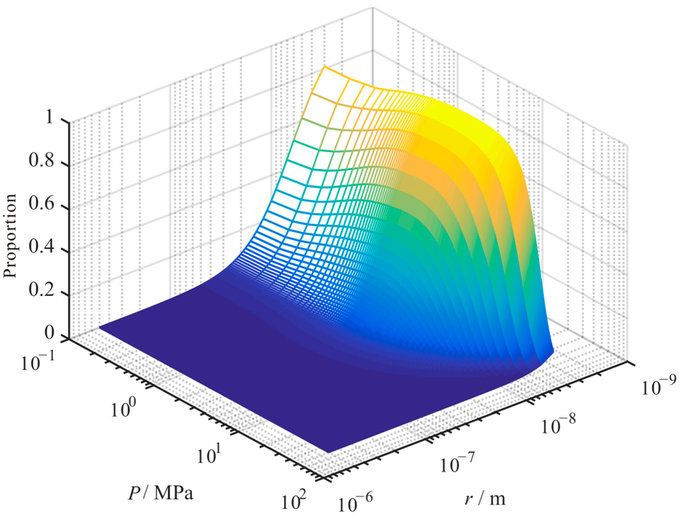
The contribution ratio of each transport mechanism to the matrix’s apparent permeability is further analyzed. Under the condition of constant temperature, the contribution ratio of Knudsen diffusion to the matrix’s apparent permeability increased with the decrease in pressure. Moreover, its contribution ratio increased first and then decreased with the increase in pore size (see Figure 16). As Figure 17 shows, the contribution proportion of Knudsen diffusion to the apparent permeability increases with the increase in temperature, which variation decreases with the increase in pore size and pressure.
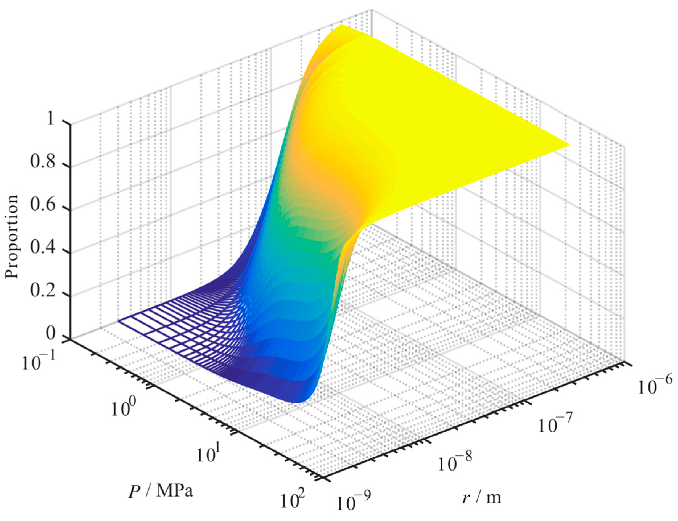
Under the condition of constant temperature, the contribution ratio of slippage flow to the matrix’s apparent permeability decreased with the decrease in pressure. Moreover, its contribution ratio increased with the increase in pore size (see Figure 18). As Figure 19 shows, the contribution proportion of slippage flow to the apparent permeability decreases with the increase in temperature, which variation decreases with the increase in pore size.
Under the condition of constant temperature, the contribution ratio of surface diffusion to the matrix’s apparent permeability increased first and then decreased with the increase in pressure. Moreover, its contribution ratio decreased with the increase in pore size (see Figure 20). As Figure 21 shows, the contribution proportion of surface diffusion to the apparent permeability increases with the increase in temperature, which variation decreases with the increase in pore size.

5. Conclusions

This paper considers the changes in reservoir properties, which established a micro-transport mechanism and matrix apparent permeability model for gas in micro-nano pores and fractures of the shale matrix. The macroscopic effects under the combined action of multiple micro-transport mechanisms were studied. The conclusions are as follows:
(1)
Considering the slippage flow, Knudsen diffusion, transition flow, surface diffusion, and reservoir changing mechanism, the apparent permeability model of the shale reservoir matrix is verified by the experimental data. This model can accurately fit the changes in reservoir matrix permeability in the process of shale gas development.
(2)
The calculation of the Knudsen number should consider the impact of changes in reservoir and gas properties. Considering these influences, the Knudsen number decreases. Moreover, this decrease in the Knudsen number is more obvious under the conditions of low pressure and small pore size.
(3)
The apparent permeability of the shale reservoir matrix is significantly influenced by pressure, temperature, pore size, and TOC. As the pressure or pore size decreases, the apparent permeability decreases first and then increases. With the increase in temperature or TOC, the apparent permeability increases. With the increase in tortuosity, the apparent permeability of the reservoir matrix decreases.
(4)
The contribution proportion of the three transport mechanisms to the apparent permeability of the shale matrix is significantly influenced by pressure, temperature, pore size, and TOC. With the decrease in pressure, the proportion of slippage flow decreases, and the proportion of Knudsen diffusion increases. Moreover, the proportion of surface diffusion increases first and then decreases. With the increase in temperature, the proportion of Knudsen diffusion and surface diffusion increases, and the proportion of slippage flow decreases. With the increase in pore size, the proportion of slippage flow increases, and the proportion of surface diffusion decreases. The proportion of Knudsen diffusion increases first and then decreases. With the increase in TOC, the proportion of slippage flow decreases, and the proportion of surface diffusion increases. Moreover, the proportion of Knudsen diffusion decreases.

Author Contributions

Y.D.: developed the methodology, coded the program, and wrote the main manuscript. L.S.: discussed the methodology and conceived the work. F.L.: supervised the whole calculation. Q.Z.: discussed the model performance. C.L.: discussed the methodology. G.C.: discussed the methodology, and reviewed the manuscript. Q.C.: provided the data. S.Y.: reviewed the manuscript. J.W.: reviewed the manuscript. All authors have read and agreed to the published version of the manuscript.

Funding

This research was funded by Postdoctoral Fund Project of CNOOC Research Institute Co., Ltd., grant number 2020-KFZL-015.

Data Availability Statement

The data presented in this study are available on request from the corresponding author.

Acknowledgments

We thank all editors and anonymous reviewers for their comments and suggestions.

Conflicts of Interest

The authors declare no conflict of interest.

References

  1. Wu, K.; Chen, Z. Review of gas transport in nanopores in shale gas reservoir. Sci. Bull. 2016, 1, 91–127. [Google Scholar]
  2. Zhang, Q.; Liang, F.; Pang, Z.; Jiang, S.; Zhou, S.; Zhang, J. Lower threshold of pore-throat diameter for the shale gas reservoir: Experimental and molecular simulation study. J. Pet. Sci. Eng. 2019, 173, 1037–1046. [Google Scholar] [CrossRef]
  3. Wang, G.; Jiang, Z.; Tang, X.; He, S.; Wang, Y.; Chang, J. Critical conditions and capabilities of shale gas diffusion and seepage types in the Longmaxi Format. Acta Geol. Sin. 2023, 97, 210–220. [Google Scholar]
  4. Yang, X.; Zhou, W.; Liu, X.; Yan, Y. A multiscale approach for simulation of shale gas transport in organic nanopores. Energy 2020, 210, 118547. [Google Scholar] [CrossRef]
  5. Zeng, J.; Liu, J.; Guo, J. Characterization of gas transport in shale: A multi-mechanism permeability modeling approach. Chem. Eng. J. 2022, 438, 135604. [Google Scholar] [CrossRef]
  6. Wu, K.; Li, X.; Chen, Z. Micro-scale effects of gas transport in organic nanopores of shale gas reservoirs. Nat. Gas Ind. 2016, 36, 51–64. [Google Scholar]
  7. Florence, F.A.; Rushing, J.; Newsham, K.E.; Blasingame, T.A. Improved permeability prediction relations for low permeability sands. In Proceedings of the Rocky Mountain Oil & Gas Technology Symposium, Denver, CO, USA, 16–18 April 2007. [Google Scholar]
  8. Cipolla, C.; Lolon, E.; Mayerhofer, M. Reservoir Modeling and Production Evaluation in Shale-Gas Reservoirs. In Proceedings of the International Petroleum Technology Conference, Doha, Qatar, 7–9 December 2009. [Google Scholar] [CrossRef]
  9. Sheng, M.; Li, G.; Huang, W.; Tian, S. Shale gas transient flow model with effects of surface diffusion. Acta Pet. Sin. 2014, 35, 347–352. [Google Scholar]
  10. Yin, Y.; Qu, Z.; Zhang, J. An analytical model for shale gas transport in kerogen nanopores coupled with real gas effect and surface diffusion. Fuel 2017, 210, 569–577. [Google Scholar] [CrossRef]
  11. Li, X.; Liu, S.; Li, J.; Tan, X. Apparent gas permeability model of shale matrix coupling stress sensitivity and water saturation. Nat. Gas Geosci. 2021, 223, 861–870. [Google Scholar]
  12. Wu, K.; Li, X.; Chen, Z. Real gas transport through nanopores of shale gas reservoir. Sci. Sin. Technol. 2016, 46, 68–78. [Google Scholar] [CrossRef]
  13. Ertekin, T.; King, G.A.; Schwerer, F.C. Dynamic gas slippage: A unique dual-mechanism approach to the flow of gas in tight formations. SPE Form. Eval. 1986, 1, 43–52. [Google Scholar] [CrossRef]
  14. Clarkson, C.R.; Nobakht, M.; Kaviani, D.; Ertekin, T. Production analysis of tight-gas and shale-gas reservoirs using the dynamic-slippage concept. SPE J. 2012, 17, 230–242. [Google Scholar] [CrossRef]
  15. Javadpour, F. Nanopores and apparent permeability of gas flow in mudrocks (shales and siltstone). J. Can. Pet. Technol. 2009, 48, 16–21. [Google Scholar] [CrossRef]
  16. Swami, V.; Settari, A. A Pore Scale Gas Flow Model for Shale Gas Reservoir. In Proceedings of the American Unconventional Resources Conference, Pittsburgh, PA, USA, 5–7 June 2012. [Google Scholar]
  17. Li, D.; Zhang, Y.; Sun, X.; Zhao, F.; Cui, X.; Qiao, W.; Su, Y. A new model for assessing apparent permeability of shale gas at real gas condition considering surface diffusion. J. China Univ. Pet. (Ed. Nat. Sci.) 2018, 42, 82–90. [Google Scholar]
  18. Tian, S.; Wang, T.; Li, G.; Sheng, M.; Liu, Q.; Zhang, S. An analytical model for shale gas transport in circular tube pores. Int. J. Heat Mass Transf. 2018, 127, 321–328. [Google Scholar] [CrossRef]
  19. Huang, T.; Tan, W.; Zhuang, Q.; Wang, G.; Yin, T. Coupling model for nanopore gas transport in shale reservoir. J. Southwest Pet. Univ. (Sci. Technol. Ed.) 2019, 41, 118–126. [Google Scholar]
  20. Song, H.; Li, B.; Chen, S.; Li, J.; Gao, Z. Evolution mechanism of dynamic apparent permeability of shale reservoirs. J. China Univ. Min. Technol. 2022, 248, 873–885. [Google Scholar]
  21. Villazon, G.; Sigal, R.F.; Civan, F.; Devegowda, D. Parametric Investigation of Shale Gas Production Considering Nano-Scale Pore Size Distribution. In Proceedings of the SPE Annual Technical Conference and Exhibition, Denver, CO, USA, 30 October–2 November 2011. [Google Scholar]
  22. Roy, S.; Raju, R.; Chuang, H.F.; Cruden, B.A.; Meyyappan, M. Modeling gas flow through microchannels and nanopores. J. Appl. Phys. 2003, 93, 4870–4879. [Google Scholar] [CrossRef]
  23. Zheng, D.; Ozbayoglu, E.; Miska, S.; Zhang, J. Experimental Study of Anisotropic Strength Properties of Shale. In Proceedings of the 57th U.S. Rock Mechanics/Geomechanics Symposium, Atlanta, GA, USA, 25–28 June 2023. [Google Scholar]
  24. Zheng, D.; Ozbayoglu, E.; Miska, S.; Zhang, J. Combined Experimental and Well Log Study of Anisotropic Strength of Shale. In Proceedings of the SPE Annual Technical Conference and Exhibition, San Antonio, TX, USA, 16–18 October 2023. [Google Scholar]
  25. Liu, J.; Bai, X.; Elsworth, D. Evolution of pore systems in low-maturity oil shales during thermal upgrading—Quantified by dynamic SEM and machine learning. Pet. Sci. 2024, in press. [Google Scholar] [CrossRef]
  26. Javadpour, F.; Fisher, D.; Unsworth, M. Nanoscale gas flow in shale gas sediments. J. Can. Pet. Technol. 2007, 46, 55–61. [Google Scholar] [CrossRef]
  27. Wu, K.; Chen, Z.; Li, X.; Guo, C.; Wei, M. A model for multiple transport mechanisms through nanopores of shale gas reservoirs with real gas effect-adsorption-mechanic coupling. Int. J. Heat Mass Transf. 2016, 93, 408–426. [Google Scholar] [CrossRef]
  28. Shi, J.; Lei, Z.; Li, Y.; Wei, Y.; Tao, W. Diffusion and flow mechanisms of shale gas through matrix pores and gas production forecasting. In Proceedings of the SPE Unconventional Reservoir Conference, Calgary, AB, Canada, 5–7 November 2013. [Google Scholar]
  29. Raghavan, R.; Chin, L.Y. Productivity changes in reservoirs with stress-dependent permeability. SPE Reserv. Eval. Eng. 2004, 7, 308–315. [Google Scholar] [CrossRef]
  30. Fu, X.; Li, D.; Qin, Y.; Jiang, B.; Wang, W.; Li, G. Experimental Research of Influence of Coal Matrix Shrinkage on Permeability. J. China Univ. Min. Technol. 2002, 31, 129–131. [Google Scholar]
  31. Cao, C.; Li, T.; Zhang, L.; Gao, C.; Wang, H. Shale gas dual porosity-dual permeability model with matrix shrinking. Nat. Gas Geosci. 2015, 26, 2381–2387. [Google Scholar]
  32. Wang, S.; Elsworth, D.; Liu, J. A mechanistic model for permeability evolution in fractured sorbing media. J. Geophys. Res. 2012, 117, 6205–6221. [Google Scholar] [CrossRef]
  33. Dong, Y.; Zhao, Q.; Lu, C.; Lu, C.; Gan, Y.; Chen, G. High-pressure isothermal adsorption model for supercritical methane in shale. In Proceedings of the 2022 International Field Exploration and Development Conference, IFEDC, Xi’an, China, 16–18 November 2022; Springer Science and Business Media Deutschland GmbH: Singapore, 2022. [Google Scholar]
  34. Shi, R.; Liu, J.; Derek, E. Mechanistic Analysis of Shale Permeability Evolution Data. In Proceedings of the Unconventional Resources Technology Conference, Denver, CO, USA, 22–24 July 2019. [Google Scholar]
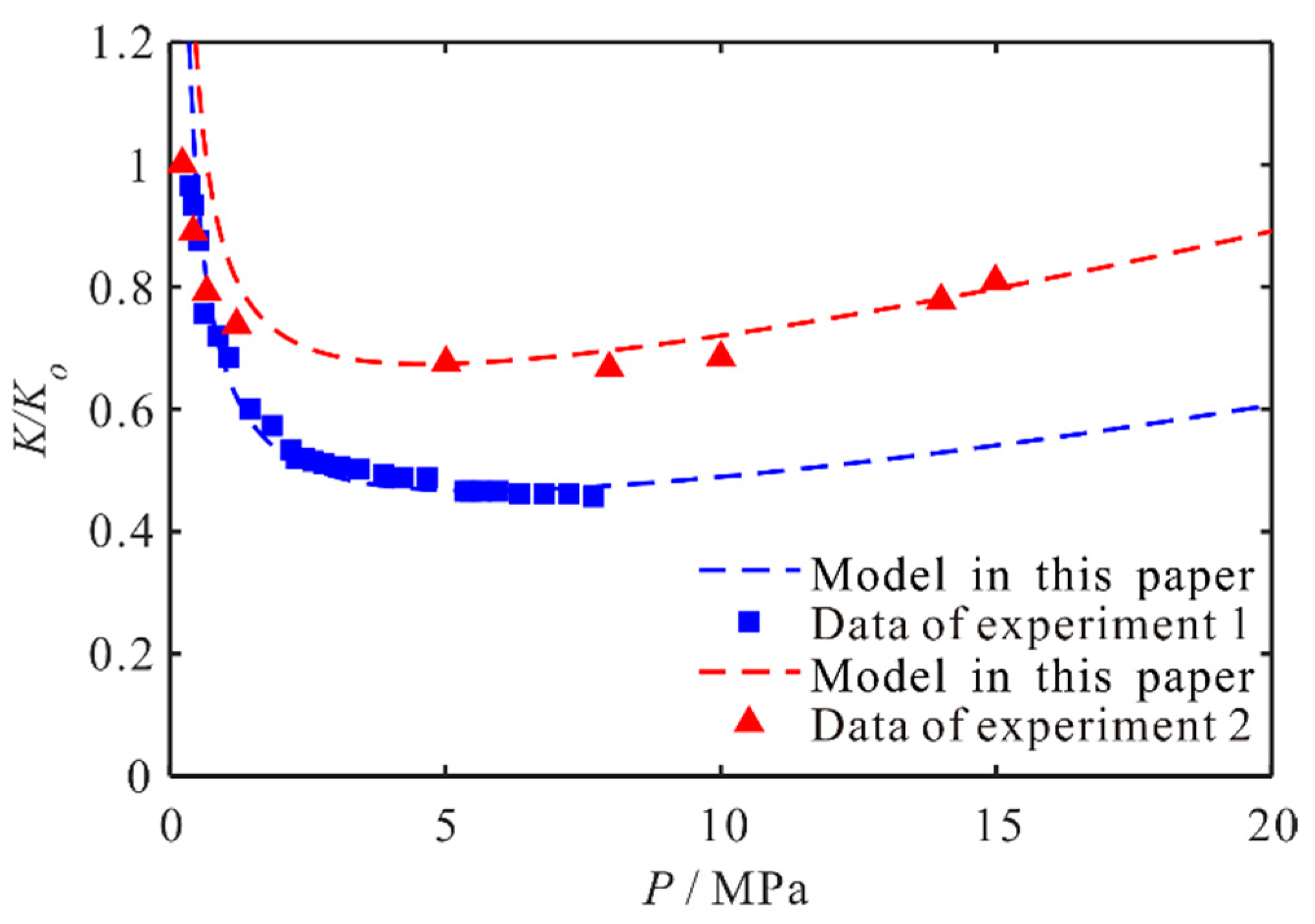
Figure 1. Comparison of permeability between experimental data and the model presented in this paper.
Energies 17 01145 g001
Figure 2. Relationship between Knudsen number and pressure, temperature, and pore size.
Energies 17 01145 g002
Figure 3. Distribution range of Knudsen number for different pore sizes and pressures.
Energies 17 01145 g003
Figure 4. The influence of various transport mechanisms on the apparent permeability of shale matrix with changes in pressure. (a) The apparent permeability. (b) The contributions for the apparent permeability.
Energies 17 01145 g004
Figure 5. The variation trend of apparent permeability of shale matrix with pressure.
Energies 17 01145 g005
Figure 6. The influence of various transport mechanisms on the apparent permeability of shale matrix with changes in temperature. (a) The apparent permeability. (b) The contributions for the apparent permeability.
Energies 17 01145 g006
Figure 7. The variation trend of apparent permeability of shale matrix with temperature.
Energies 17 01145 g007
Figure 8. The influence of various transport mechanisms on the apparent permeability of shale matrix with changes in the pore size. (a) The apparent permeability. (b) The contributions for the apparent permeability.
Energies 17 01145 g008
Figure 9. The variation trend of apparent permeability of shale matrix with pore size.
Energies 17 01145 g009
Figure 10. The influence of various transport mechanisms on the apparent permeability of shale matrix with changes in the tortuosity. (a) The apparent permeability. (b) The contributions for the apparent permeability.
Energies 17 01145 g010
Figure 11. The variation trend of apparent permeability of shale matrix with the tortuosity.
Energies 17 01145 g011
Figure 12. The influence of various transport mechanisms on the apparent permeability of shale matrix with changes in the TOC. (a) The apparent permeability. (b) The contributions for the apparent permeability.
Energies 17 01145 g012
Figure 13. The variation trend of apparent permeability of shale matrix with the TOC.
Energies 17 01145 g013
Figure 14. The relationship of the apparent permeability of shale matrix, pore size, and pressure.
Energies 17 01145 g014
Figure 15. The relationship of the apparent permeability of shale matrix, pore size, and pressure under different temperature conditions.
Energies 17 01145 g015
Figure 16. The various relationships for the contribution proportion of the Knudsen diffusion to the matrix apparent permeability with pore size and pressure.
Energies 17 01145 g016
Figure 17. The various relationships for the contribution proportion of the Knudsen diffusion to the matrix apparent permeability with pore size and pressure, under different temperature conditions.
Energies 17 01145 g017
Figure 18. The various relationships for the contribution proportion of the slippage flow to the matrix apparent permeability with pore size and pressure.
Energies 17 01145 g018
Figure 19. The various relationships for the contribution proportion of the slippage flow to the matrix apparent permeability with pore size and pressure under different temperature conditions.
Energies 17 01145 g019
Figure 20. The various relationships for the contribution proportion of the surface diffusion to the matrix apparent permeability with pore size and pressure.
Energies 17 01145 g020
Figure 21. The various relationships for the contribution proportion of the surface diffusion to the matrix apparent permeability with pore size and pressure, under different temperature conditions.
Energies 17 01145 g021
Table 1. The fitting parameters of the apparent permeability model.
Fitting Parameters (Experiment 1)ValuesFitting Parameters (Experiment 2)Values
Initial pressure Po (MPa)40Initial pressure Po (MPa)25
Porosity ϕ (f)0.015Porosity ϕ (f)0.05
Rock compressibility factor Cp (MPa−1)0.013Rock compressibility factor Cp (MPa−1)0.012
Table 2. Calculation parameters for the bulk gas transport model.
ParametersValuesParametersValues
Temperature T (K)300Fluid viscosity μ (mPa·s)0.0175
Porosity ϕ (f)0.05Molecular molar mass M (kg/mol)0.028
Tortuosity τ (f)4.3The ratio of molecular diameter to local pore diameter σ (f)0.5
Fracture width h (nm)50Fractal dimension of pore wall Df (f)2.5
Disclaimer/Publisher’s Note: The statements, opinions and data contained in all publications are solely those of the individual author(s) and contributor(s) and not of MDPI and/or the editor(s). MDPI and/or the editor(s) disclaim responsibility for any injury to people or property resulting from any ideas, methods, instructions or products referred to in the content.