
Feasibility and Performance Analysis of Cylinder Deactivation for a Heavy-Duty Compressed Natural Gas Engine

 ,
,  ,
,  , and
, and 
Highlights
- A cylinder deactivation strategy, typically employed in automotive applications, has been implemented in a heavy-duty CNG engine, showing significant fuel economy benefits in specific conditions of the entire workplan.
- Cylinder deactivation increases exhaust gas temperatures, improving three-way Catalyst conversion efficiency.
- Lower fuel consumption and reduced emissions indicate the potential for broader adoption in heavy-duty engines keeping the same performance.
- Improved catalyst activity due to higher exhaust temperatures could reduce the amount of PGM, promoting cost-effective emissions management.
Abstract

1. Introduction
- Higher efficiency: the benefit is higher for larger engines because they work at lower loads, and for low engine speed and low gears due to higher throttling at low gears [10].
- Improved combustion and lower cylinder-wall heat losses [12].
- Mixed lubrication and increased engine oil consumption: the former is caused by higher temperature and pressure on the bearings. In this case, the use of special coatings and a precise minimum lubricant film thickness can solve the problem. This kind of lubrication can lead to significant power losses [15]. The latter is caused by lower in-cylinder pressure during the intake stroke and lower temperature of the piston rings in the deactivated cylinders. The increased introduction of oil due to more frequent movements of the top ring can also cause higher exhaust smoke. In these cases, solutions can be reducing the ring grooves clearances or ring gap dimensions [6,16]. In addition, uneven and increased wear can arise due to the reduced lubricant film thickness and pressure peaks inside the cylinder [6,14].
- Compressor surge line: deactivating some cylinders can result in a movement of the surge line to the right, with a consequent greater sensitivity to the pulsations frequency [18].
- Higher temperature on components: especially in the upper section of the cylinders liners and the lower part of the exhaust valves [19].
- Increased gas leakage: these losses are however overcome by the CDA benefits [6].
- Exhaust gas: this leads to higher temperatures which, in turn, cause greater crankshaft irregularities, higher friction, and work loss due to the blow-by. Thus, the deactivation must be maintained for at least 10 cycles to achieve a stabilisation of the pressure and the fuel consumption benefit. However, the cylinders cool down more slowly, so they are reactivated more easily [20].
- Fresh air: it gives lower pressures and irregularities on the crankshaft but has issues when reactivating the cylinder due to the loss of tumble or swirl. Introducing fresh charge could also cause unnecessary enrichment caused by the oxygen sensor detecting fresh air [6].
- Empty cylinder: avoiding opening the intake valves after the exhaust gases are expelled, the cylinder remains in an almost vacuum state. This can lead to very important benefits, but has the considerable drawback of oil suction into the combustion chamber [6].
2. Model and Experimental Campaign
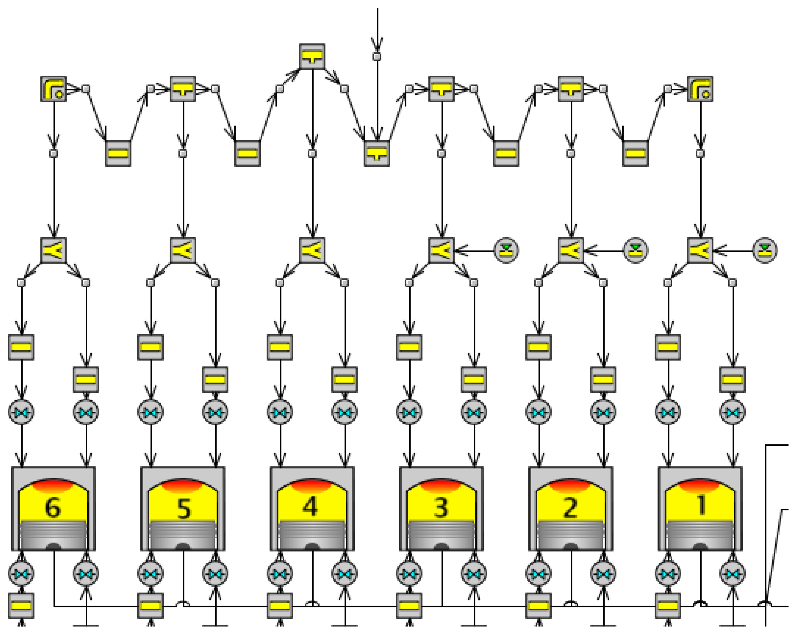
2.1. Engine Model Description
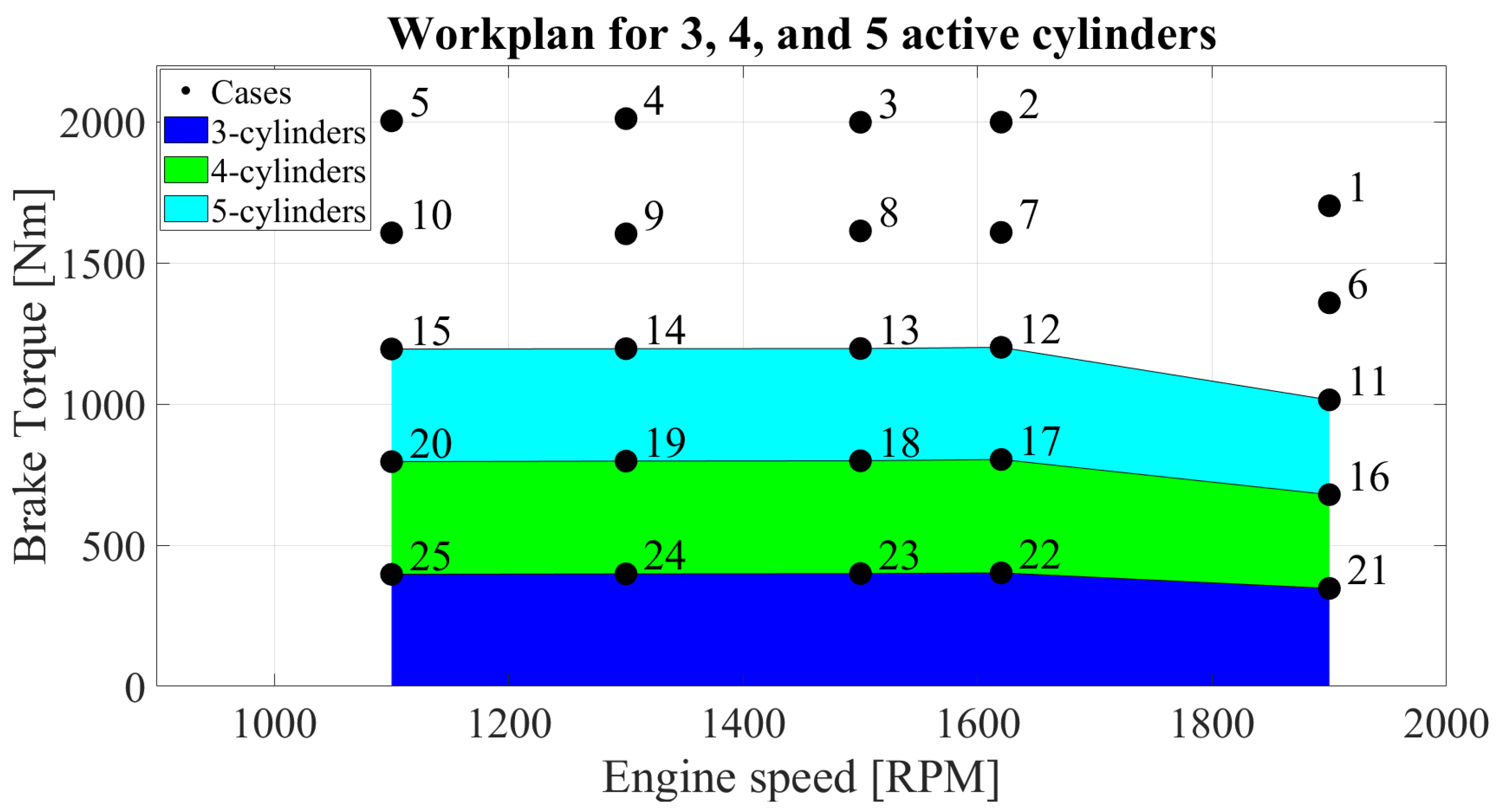
2.2. Steady-State Model Feasibility Study
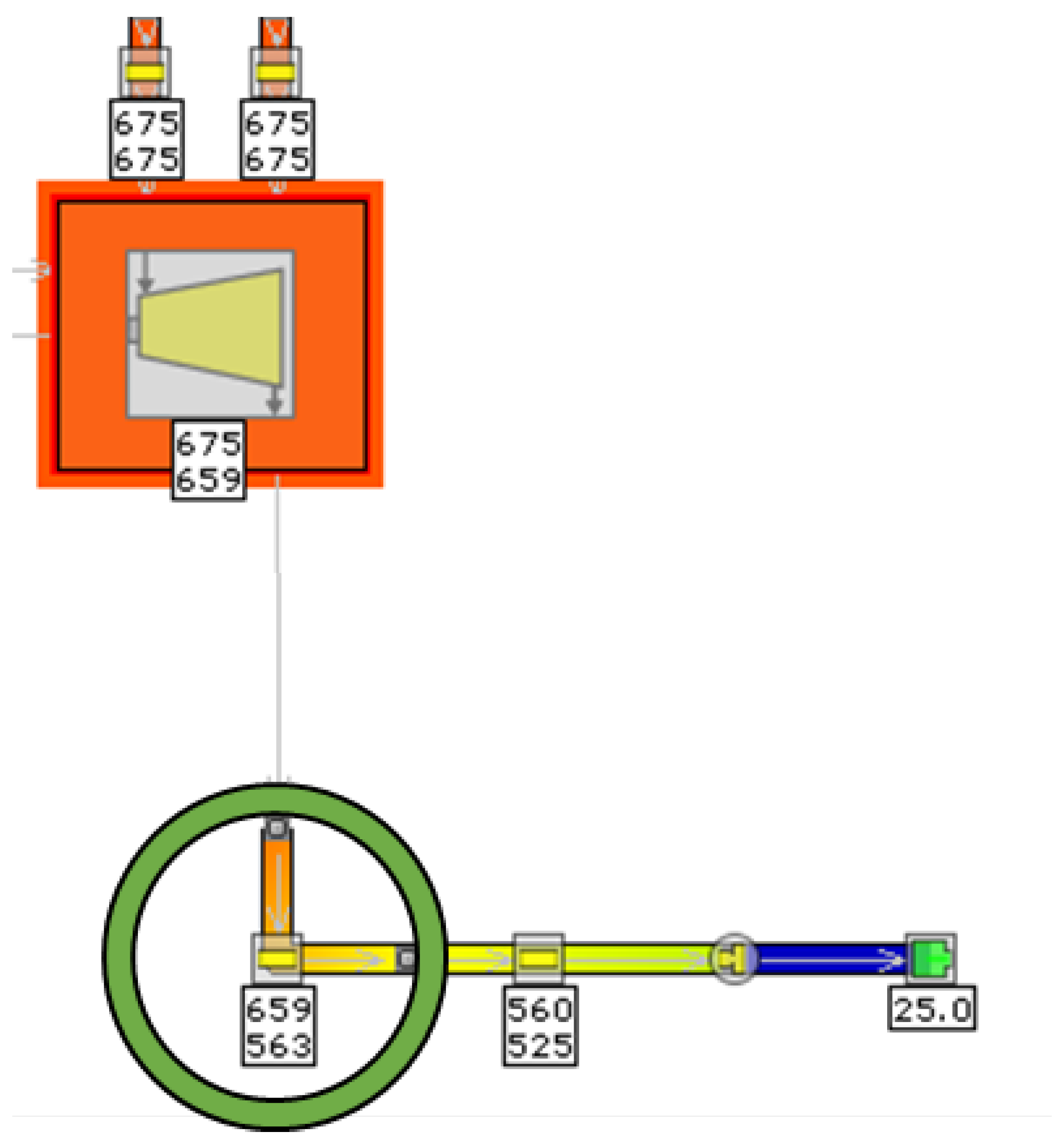
2.3. Cylinder Deactivation by Exhaust Gas Recirculation
3. Transient Analysis
Transient Analysis Results
4. Conclusions
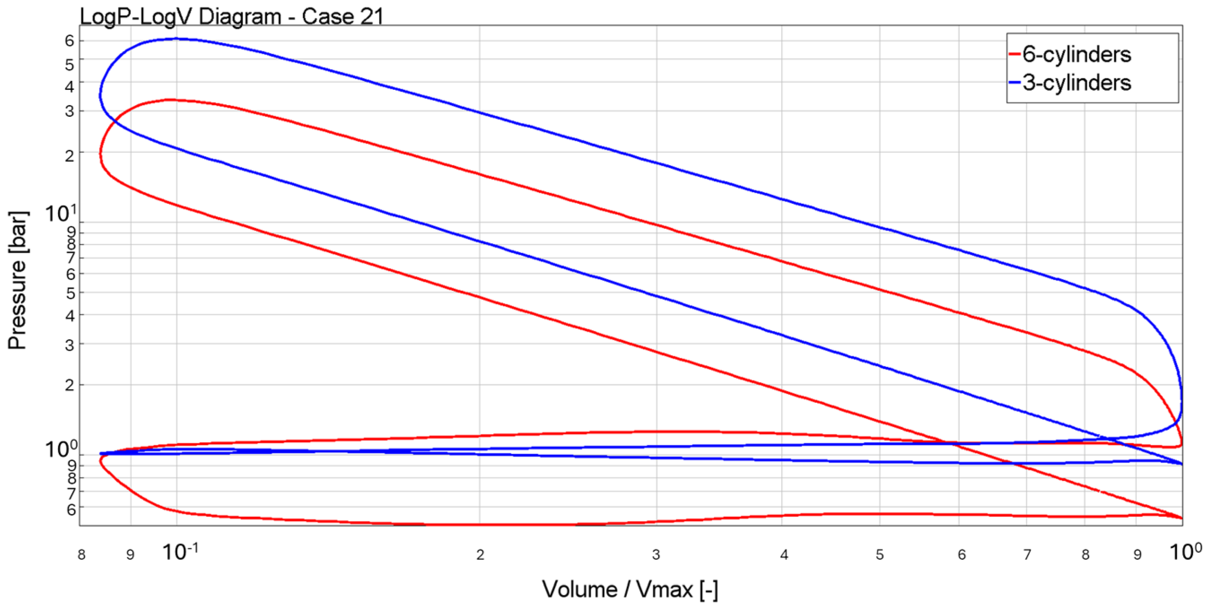
- Among the several configurations proposed, the fixed three-cylinder deactivation, by recirculating exhaust gas in the three deactivated cylinders, can be considered as the most promising one, thanks to the high benefit in fuel consumption and exhaust gases temperature with temperature increases up to 62 °C in the SS operating tested condition at 20% torque, and up to 19 °C during the selected WHTC portion considered, in which the major fuel reduction benefits are present (up to −10%).
- This study sets the stage for an application of a cylinder deactivation strategy also in large displacement heavy-duty engines, which is currently only implemented in some passenger cars, with the utilisation of simple hardware modifications. The exhaust temperature increment can enhance the Three-Way Catalyst (TWC) performances in terms of conversion efficiency in standard operating conditions, allowing to speed up the reach of the light-off temperature, encouraging a potential reduction in the amount of noble materials or the volume of the catalytic converter.
- An extensive experimental characterisation will be carried out as one of the future developments of the activity, in order to validate the concept and promote a deeper understanding of the working areas in which CDA strategy can be adopted.
Author Contributions
Funding
Data Availability Statement
Conflicts of Interest
Abbreviations
| ATS | After-Treatment System |
| BSFC | Brake Specific Fuel Consumption |
| BTE | Brake Thermal Efficiency |
| CDA | Cylinder Deactivation |
| CNG | Compressed Natural Gas |
| DSF | Dynamic Skip Fire |
| ECU | Engine Control Unit |
| EGR | Exhaust Gas Recirculation |
| GHGs | Greenhouse Gases |
| HD | Heavy-Duty |
| iEGR | Internal Exhaust Gas Recirculation |
| IMEP | Indicated Mean Effective Pressure |
| MFB50 | Mass Burned Fraction at 50% |
| NVH | Noise Vibration Harshness |
| PMEP | Pumping Mean Effective Pressure |
| SI | Spark Ignition |
| TWC | Three-Way Catalyst |
| VVA | Variable Valve Actuation |
| WHTC | World Harmonized Transient Cycle |
| Glossary | |
| Air–fuel equivalence ratio | |
| Fuel–air equivalence ratio | |
| CO2 | Carbon dioxide |
References
- Intergovernmental Panel on Climate Change IPCC. Synthesis Report of the IPCC Sixth Assesment Report (AR6); Technical Report; IPCC: Geneva, Switzerland, 2023. [Google Scholar]
- European Environment Agency. The European Environment: State and Outlook 2020: Knowledge for Transition to a Sustainable Europe; Publications Office of the European Union: Luxembourg, 2019; 496p. [Google Scholar]
- United Nations Environment Programme. Emissions Gap Report 2022, The Closing Window, Climate Crisis Calls for Rapid Transformation of Societies; UNEP: Nairobi, Kenya, 2022. [Google Scholar]
- IEA. World Energy Outlook 2022; IEA: Paris, France, 2022; Available online: https://www.iea.org/reports/world-energy-outlook-2022 (accessed on 19 December 2023).
- Khan, M.I.; Yasmin, T.; Shakoor, A. Technical overview of compressed natural gas (CNG) as a transportation fuel. Renew. Sustain. Energy Rev. 2015, 51, 785–797. [Google Scholar] [CrossRef]
- Fridrichová, K.; Drápal, L.; Vopařil, J.; Dlugoš, J. Overview of the potential and limitations of cylinder deactivation. Renew. Sustain. Energy Rev. 2021, 146. [Google Scholar] [CrossRef]
- Zhao, J.; Xi, Q.; Wang, S.; Wang, S. Improving the partial-load fuel economy of 4-cylinder SI engines by combining variable valve timing and cylinder-deactivation through double intake manifolds. Appl. Therm. Eng. 2018, 141, 245–256. [Google Scholar] [CrossRef]
- Douglas, K.J.; Milovanovic, N.; Turner, J.W.G.; Blundell, D. Fuel Economy Improvement Using Combined CAI and Cylinder Deactivation (CDA)–An Initial Study; SAE International: Warrendale, PA, USA, 2005. [Google Scholar]
- Sun, Z.; Hong, J.; Zhang, T.; Sun, B.; Yang, B.; Lu, L.; Li, L.; Wu, K. Hydrogen engine operation strategies: Recent progress, industrialization challenges, and perspectives. Int. J. Hydrogen Energy 2023, 48, 366–392. [Google Scholar] [CrossRef]
- Leone, T.G.; Pozar, M. Fuel Economy Benefit of Cylinder Deactivation-Sensitivity to Vehicle Application and Operating Constraints; SAE Technical Paper 2001-01-3591; SAE International: Warrendale, PA, USA, 2001. [Google Scholar]
- Muhamad Said, M.; Latiff, Z.; Zainal Abidin, S.; Zahari, I. Investigation of Intake Valve Strategy on the Cylinder Deactivation Engine. Appl. Mech. Mater. 2016, 819, 459–465. [Google Scholar] [CrossRef]
- Middendorf, H.; Theobald, J.; Lang, L.; Hartel, K. The 1.4-l TSI Gasoline Engine with Cylinder Deactivation. MTZ Worldw. 2012, 73, 4–9. [Google Scholar] [CrossRef]
- Brinklow, G.; Herreros, J.M.; Rezaei, S.Z.; Omid, D.; Millington, P.; Kolpin, A. Impact of Cylinder Deactivation Strategies on Three-way Catalyst Performance in High Efficiency Low Emissions Engines. Chem. Eng. J. Adv. 2023, 14, 4–9. [Google Scholar] [CrossRef]
- Turnbull, R.; Dolatabadi, N.; Rahmani, R.; Rahnejat, H. Energy loss and emissions of engine compression rings with cylinder deactivation. Proc. Inst. Mech. Eng. Part D J. Automob. Eng. 2021, 235, 1930–1943. [Google Scholar] [CrossRef]
- Mohammadpour, M.; Rahmani, R.; Rahnejat, H. Effect of cylinder deactivation on the tribo-dynamics and acoustic emission of overlay big end bearings. Proc. Inst. Mech. Eng. Part K J. Multi-Body Dyn. 2014, 228, 138–151. [Google Scholar] [CrossRef]
- Ma, Z. Oil Transport Analysis of a Cylinder Deactivation Engine; SAE Technical Paper 2010-01-1098; SAE International: Warrendale, PA, USA, 2010. [Google Scholar] [CrossRef]
- Baykara, C.; Akin Kutlar, O.; Dogru, B.; Arslan, H. Skip cycle method with a valve-control mechanism for spark ignition engines. Energy Convers. Manag. 2017, 146, 134–146. [Google Scholar] [CrossRef]
- Vijayakumar, R.; Akehurst, S.; Liu, Z.; Reyes-Belmonte, M.A.; Brace, C.J.; Liu, D.; Copeland, C. Design and testing a bespoke cylinder head pulsating flow generator for a turbocharger gas stand. Energy 2019, 189, 116291. [Google Scholar] [CrossRef]
- Bech, A.; Shayler, P.J.; McGhee, M. The Effects of Cylinder Deactivation on the Thermal Behaviour and Performance of a Three Cylinder Spark Ignition Engine. SAE Int. J. Engines 2016, 9, 1999–2009. [Google Scholar] [CrossRef]
- Faust, H.; Scheidt, M. Potentials and Constraints of Cylinder Deactivation in the Powertrain. MTZ Worldw. 2016, 77, 72–77. [Google Scholar] [CrossRef]
- Ess, J.V.; Wolk, B.; Fuschetto, J.; Wang, R.; Younkins, M. Method to Compensate Fueling for Individual Firing Events in a Four-Cylinder Engine Operated with Dynamic Skip Fire. SAE Int. J. Engines 2018, 11, 977–991. [Google Scholar] [CrossRef]
- Baratta, M.; Misul, D.; Xu, J. Development and application of a method for characterizing mixture formation in a port-injection natural gas engine. Energy Convers. Manag. 2021, 227, 113595. [Google Scholar] [CrossRef]
- Hoffmann, H.; Loch, A.; Widmann, R.; Kreusen, G.; Meehsen, D.; Rebbert, M. Cylinder Deactivation for Valve Trains with Roller Finger Follower. MTZ Worldw. 2009, 70, 26–30. [Google Scholar] [CrossRef]
- Maehara, H.; Kitawaki, S.; Abe, T.; Saito, S.; Tsukui, T. Development of Variable Cylinder Management System for Large Motorcycles–An Effective Way of Reducing Output Change at Switching of the Number of Working Cylinders; SAE Technical Paper 2010-32-0117; SAE International: Warrendale, PA, USA, 2010. [Google Scholar] [CrossRef]
- Ihlemann, A.; Nitz, N. Cylinder Deactivation a Technology with a Future or a Niche Application? Schaeffler Symposium. 2014. Available online: https://api.semanticscholar.org/CorpusID:204860287 (accessed on 19 December 2023).
- Kreuter, P.; Heuser, P.; Reinicke-Murmann, J.; Erz, R.; Stein, P.; Peter, U. Meta-CVD system: An electro-mechanical cylinder and valve deactivation system. SAE Trans. 2001, 110, 107–117. [Google Scholar]
- Flierl, R.; Lauer, F. Mechanically Fully Variable Valvetrain and Cylinder Deactivation. MTZ Worldw. 2013, 74, 50–57. [Google Scholar] [CrossRef]
- Millo, F.; Mirzaeian, M.; Luisi, S.; Doria, V.; Stroppiana, A. Engine displacement modularity for enhancing automotive s.i. engines efficiency at part load. Fuel 2016, 180, 645–652. [Google Scholar] [CrossRef]
- Di Maio, D.; Stramaccioni, E.; Misul, D.A.; Napolitano, P.; Beatrice, C. A Multiphysics Co-Simulation Framework of a Gas Engine and Three-Way Catalyst toward a Complete Vehicle Design Model. Machines 2022, 10, 852. [Google Scholar] [CrossRef]
- Duan, X.; Liu, Y.; Liu, J.; Lai, M.C.; Jansons, M.; Guo, G.; Zhang, S.; Tang, Q. Experimental and numerical investigation of the effects of low-pressure, high-pressure and internal EGR configurations on the performance, combustion and emission characteristics in a hydrogen-enriched heavy-duty lean-burn natural gas SI engine. Energy Convers. Manag. 2019, 195, 1319–1333. [Google Scholar] [CrossRef]
- Sun, X.; Liu, H.; Duan, X.; Guo, H.; Li, Y.; Qiao, J.; Liu, Q.; Liu, J. Effect of hydrogen enrichment on the flame propagation, emissions formation and energy balance of the natural gas spark ignition engine. Fuel 2022, 307, 121843. [Google Scholar] [CrossRef]


| Engine Specifications | Values |
|---|---|
| Type | Turbocharged, CNG, SI |
| Cylinders arrangement | 6 cylinders in line |
| Engine displacement | 12.9 L |
| Bore | 135 mm |
| Stroke | 150 mm |
| Compression ratio | 12:1 |
| Rated power | 338 kW @ 2000 rpm |
| Torque | 2000 Nm @ 1100–1620 rpm |
| Valves per cylinder | 4 |
| Injection system | Multi-Point Injection (MPI) |
| Air-fuel equivalence ratio | 1 |
| Turbocharger control | Wastegate valve |
| After-treatment system | Three-Way Catalyst |
| Case | Torque % | 3-Cylinders Torque Difference | 4-Cylinders Torque Difference | 5-Cylinders Torque Difference |
|---|---|---|---|---|
| 11 | 60% | −49% | −22% | 0% |
| 16 | 40% | −36% | −7% | 0% |
| 21 | 20% | −7% | −2% | 0% |
| 12 | 60% | −50% | −27% | −5% |
| 17 | 40% | −37% | −7% | 0% |
| 22 | 20% | −8% | −2% | 0% |
| 13 | 60% | −49% | −27% | −5% |
| 18 | 40% | −36% | −7% | 0% |
| 23 | 20% | −5% | −2% | 0% |
| 14 | 60% | −48% | −27% | −5% |
| 19 | 40% | −38% | −10% | 0% |
| 24 | 20% | −6% | −2% | 0% |
| 15 | 60% | −48% | −27% | −6% |
| 20 | 40% | −40% | −14% | 0% |
| 25 | 20% | −3% | −2% | 0% |
| Case | Torque & Engine Speed | 6-Cylinders T [°C] | 3-Cylinders T [°C] | T Increment [°C] | T Increment [%] |
|---|---|---|---|---|---|
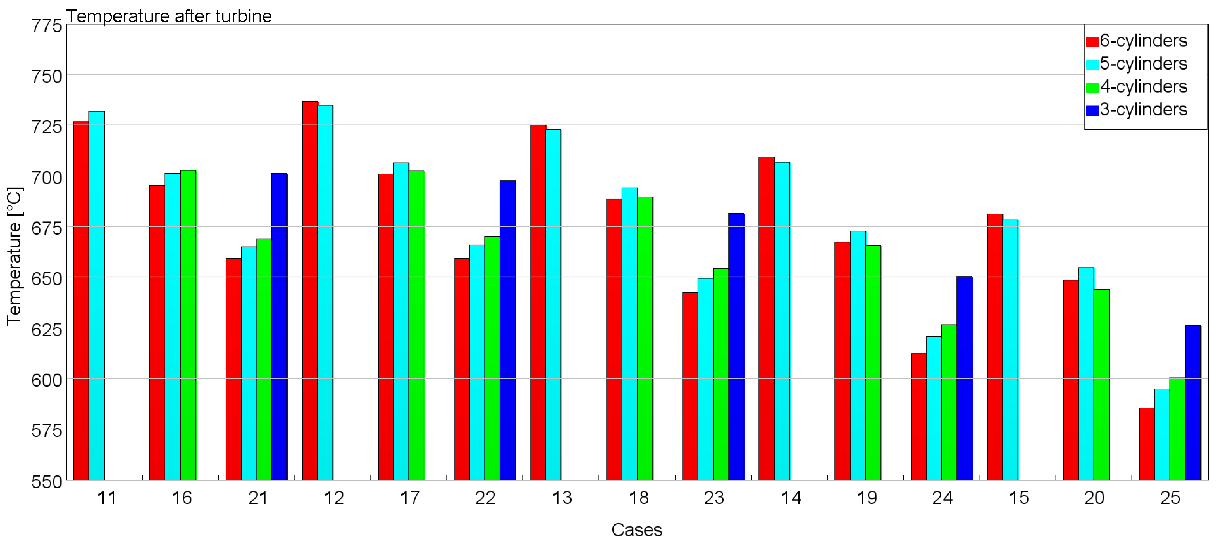
| 21 | 20% torque 1900 RPM | 659 | 701 | 42 | 6% |
| 22 | 20% torque 1620 RPM | 659 | 698 | 38 | 6% |
| 23 | 20% torque 1500 RPM | 642 | 682 | 39 | 6% |
| 24 | 20% torque 1300 RPM | 612 | 650 | 38 | 6% |
| 25 | 20% torque 1100 RPM | 585 | 626 | 41 | 7% |
| Case | Torque & Engine Speed | 6-Cylinders Volumetric Efficiency [-] | 3-Cylinders Volumetric Efficiency [-] | Volumetric Efficiency Increment |
|---|---|---|---|---|
| 21 | 20% torque 1900 RPM | 0.37 | 0.68 | 86% |
| 22 | 20% torque 1620 RPM | 0.40 | 0.73 | 82% |
| 23 | 20% torque 1500 RPM | 0.40 | 0.75 | 85% |
| 24 | 20% torque 1300 RPM | 0.41 | 0.75 | 83% |
| 25 | 20% torque 1100 RPM | 0.41 | 0.77 | 88% |
| Cases | 6-Cylinders PMEP [mbar] | 3-Cylinders PMEP [mbar] | PMEP Difference [%] |
|---|---|---|---|
| 21 | −617 | −184 | −70% |
| 22 | −550 | −114 | −79% |
| 23 | −539 | −64 | −88% |
| 24 | −508 | −60 | −88% |
| 25 | −495 | −108 | −78% |
| Cases | 3-Cylinders Fuel Flow Rate Decrement | 4-Cylinders Fuel Flow Rate Decrement | 5-Cylinders Fuel Flow Rate Decrement |
|---|---|---|---|
| 11 | - | - | −2% |
| 16 | - | −10% | −2% |
| 21 | −7% | −6% | −3% |
| 12 | - | - | −6% |
| 17 | - | −8% | −2% |
| 22 | −9% | −5% | −3% |
| 13 | - | - | −6% |
| 18 | - | −9% | −2% |
| 23 | −8% | −5% | −3% |
| 14 | - | - | −6% |
| 19 | - | −11% | −2% |
| 24 | −8% | −5% | −3% |
| 15 | - | - | −6% |
| 20 | - | −14% | −2% |
| 25 | −6% | −5% | −3% |
| Case | 6-Cylinders BMEP [bar] | 3-Cylinders EGR BMEP [bar] | BMEP Difference [%] |
|---|---|---|---|
| 21 | 3.4 | 3.2 | −6% |
| 22 | 3.9 | 3.7 | −5% |
| 23 | 3.9 | 3.9 | −1% |
| 24 | 3.9 | 3.7 | −4% |
| 25 | 3.9 | 3.8 | −1% |
| Case | 6-Cylinders T [°C] | 3-Cylinders EGR T [°C] | T Increment [°C] | T Increment [%] |
|---|---|---|---|---|
| 21 | 659 | 708 | 49 | 7% |
| 22 | 659 | 708 | 48 | 7% |
| 23 | 642 | 694 | 52 | 8% |
| 24 | 612 | 665 | 53 | 9% |
| 25 | 585 | 648 | 62 | 11% |
| Case | First, Model Fuel Flow Rate Difference [%] | EGR Fuel Flow Rate Difference [%] |
|---|---|---|
| 21 | −7% | −9% |
| 22 | −9% | −8% |
| 23 | −8% | −6% |
| 24 | −8% | −7% |
| 25 | −6% | −6% |
| Case | BMEP Difference [%] | T Increment [%] | Fuel Flow Rate Difference [%] |
|---|---|---|---|
| 21 | −6% | 7% | −9% |
| 22 | −5% | 7% | −8% |
| 23 | −1% | 8% | −6% |
| 24 | −4% | 9% | −7% |
| 25 | −1% | 11% | −6% |
| Transient Cycle | |||||
|---|---|---|---|---|---|
| CDA 1 | CDA 2 | CDA 3 | |||
| Average T Difference [°C] | Average T Difference | Average T Difference [°C] | Average T Difference | Average T Difference [°C] | Average T Difference |
| +19 | +3% | +16 | +3% | +12 | +2% |
| Transient Cycle | |||||
|---|---|---|---|---|---|
| CDA 1 | CDA 2 | CDA 3 | |||
| Average Fuel Flow Rate Difference [kg/h] | Average Fuel Flow Rate Difference | Average Fuel Flow Rate Difference [kg/h] | Average Fuel Flow Rate Difference | Average Fuel Flow Rate Difference [kg/h] | Average Fuel Flow Rate Difference |
| −0.9 | −8% | −1.1 | −10% | −2.7 | −26% |
Disclaimer/Publisher’s Note: The statements, opinions and data contained in all publications are solely those of the individual author(s) and contributor(s) and not of MDPI and/or the editor(s). MDPI and/or the editor(s) disclaim responsibility for any injury to people or property resulting from any ideas, methods, instructions or products referred to in the content. |
© 2024 by the authors. Licensee MDPI, Basel, Switzerland. This article is an open access article distributed under the terms and conditions of the Creative Commons Attribution (CC BY) license (https://creativecommons.org/licenses/by/4.0/).
Share and Cite
Misul, D.A.; Scopelliti, A.; Di Maio, D.; Napolitano, P.; Beatrice, C. Feasibility and Performance Analysis of Cylinder Deactivation for a Heavy-Duty Compressed Natural Gas Engine. Energies 2024, 17, 627. https://doi.org/10.3390/en17030627
Misul DA, Scopelliti A, Di Maio D, Napolitano P, Beatrice C. Feasibility and Performance Analysis of Cylinder Deactivation for a Heavy-Duty Compressed Natural Gas Engine. Energies. 2024; 17(3):627. https://doi.org/10.3390/en17030627
Chicago/Turabian StyleMisul, Daniela Anna, Alex Scopelliti, Dario Di Maio, Pierpaolo Napolitano, and Carlo Beatrice. 2024. "Feasibility and Performance Analysis of Cylinder Deactivation for a Heavy-Duty Compressed Natural Gas Engine" Energies 17, no. 3: 627. https://doi.org/10.3390/en17030627
APA StyleMisul, D. A., Scopelliti, A., Di Maio, D., Napolitano, P., & Beatrice, C. (2024). Feasibility and Performance Analysis of Cylinder Deactivation for a Heavy-Duty Compressed Natural Gas Engine. Energies, 17(3), 627. https://doi.org/10.3390/en17030627