Abstract
Hydrogen valleys are encompassed within a defined geographical region, with various technologies across the entire hydrogen value chain. The scope of this study is to analyze and assess the different hydrogen technologies for their application within the hydrogen valley context. Emphasizing on the coupling of renewable energy sources with electrolyzers to produce green hydrogen, this study is focused on the most prominent electrolysis technologies, including alkaline, proton exchange membrane, and solid oxide electrolysis. Moreover, challenges related to hydrogen storage are explored, alongside discussions on physical and chemical storage methods such as gaseous or liquid storage, methanol, ammonia, and liquid organic hydrogen carriers. This article also addresses the distribution of hydrogen within valley operations, especially regarding the current status on pipeline and truck transportation methods. Furthermore, the diverse applications of hydrogen in the mobility, industrial, and energy sectors are presented, showcasing its potential to integrate renewable energy into hard-to-abate sectors.
1. Introduction
Renewable hydrogen can provide an efficient mean to alleviate stress on electricity grids, increase renewable energy penetration, decarbonize hard-to-electrify sectors, and enable cross-border renewable energy transportation [1,2]. Hydrogen, however, is facing several challenges related to production costs, existing infrastructure limitations, and available market [3]. These challenges related to hydrogen technologies are anticipated to be gradually addressed through the establishment, operation, and scaling-up of hydrogen valleys [4]. Hydrogen valleys are a critical step towards the full-scale implementation of the hydrogen economy, with the target to promote sustainability, reduce carbon emissions, and derisk the associated technologies.
A hydrogen valley encompasses the clustering of hydrogen production, storage, and utilization technologies within a specific geographical area, creating a complete hydrogen ecosystem. These valleys typically integrate renewable energy sources like solar, wind, or hydropower with electrolyzers that produce hydrogen [4]. Hydrogen is then stored in various forms or converted into derivatives like methanol, ammonia, or LOHC for transportation to end-users in the power, mobility, and industrial sectors. While hydrogen valleys vary in scale and involved processes, they commonly encompass significant investments from public and private sources, spanning from small-scale to large-scale operations, with annual production capacities ranging from 300 to over 4000 tons [5].
Characterized by defined geographical scopes and complete hydrogen value chains, hydrogen valleys aim to supply diverse end-users and promote industrial clustering and infrastructure sharing practices. Hydrogen valleys could include specific regions, islands, countries as well as cross-border regions. The valley concept not only facilitates significant cost savings and efficiencies through infrastructure sharing but could also create synergies among stakeholders across the value chain, including industries, academia, and government bodies. Moreover, hydrogen valleys could contribute to the cost competitiveness of hydrogen production, job creation, and the establishment of new regulatory frameworks to support this transition. Globally, there are currently 90 announced hydrogen valley projects, primarily concentrated in Europe [6]. These projects vary in scale, technologies employed, and end-use applications, with a predominant focus on green hydrogen production via electrolysis and storage as compressed gas. Transportation methods, such as trucks and pipelines, are tailored to the specific characteristics of each location, facilitating the co-location of diverse end-users within these defined geographical areas and fostering synergies towards creating sustainable hydrogen utilization schemes [5]. Figure 1 presents an overview of the involved technologies in hydrogen valleys as well as the scope of this work.
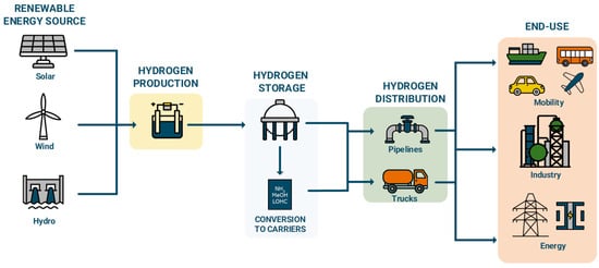
Figure 1.
Overview of involved technologies and scope of this work.
Hydrogen valleys face a multitude of challenges that, among others, encompass the lack of suppliers/mass manufacturers as well as the mass demand for hydrogen. This fact necessitates the simultaneous growth of supply and demand technologies, which can be addressed through public funding initiatives and incentives throughout the complete value chain. Societal awareness and political decision-making could also prove pivotal, with public perception influencing project acceptance and political support necessary for overcoming regulatory and financing challenges [7,8]. Furthermore, adapting hard-to-abate industrial sectors to operate with renewable hydrogen poses technical obstacles. Especially in integrating renewable energy sources and hydrogen production units into continuous industrial operations, which are further complicated by the intermittency of renewable energy sources [5]. In a similar manner with renewable energy technologies such as photovoltaic panels, hydrogen technologies must be applied in multi-GW scales to achieve significant cost reductions and efficiency improvements.
A previous review article focused on the overview of the scope, design, and current status of hydrogen valleys, emphasizing on the importance of renewable energy integration and the challenges associated with their operation [5]. Other reviews are focusing on the status of hydrogen technologies within a certain section of the value chain, such as production, storage, or end-use [9,10,11]. This study provides a comprehensive overview of technologies pertinent to the development and implementation in hydrogen valleys, addressing the aspects related to their integration within the hydrogen valley context and also outlining pathways for future research directions. Primarily, this work investigates readily available electrolysis technologies such as alkaline (AEL), proton exchange membrane (PEM), and solid oxide (SOE) electrolysis. Additionally, this review presents the challenges associated with hydrogen storage, exploring physical/chemical storage methods including gaseous/liquid hydrogen, methanol, ammonia, and LOHC, and discusses their suitability based on factors such as density, storage conditions, current status, and energy/cost considerations. Next, the study addresses the distribution of hydrogen within the geographic boundaries of the valley, focusing mainly on pipeline and truck transportation methods. Finally, this work examines the diverse applications of hydrogen in the mobility, industrial, and energy sectors, underlining its potential to promote the integration of renewable hydrogen (and in consequence renewable energy) into “hard-to-electrify” and “hard-to-abate” sectors.
2. Hydrogen Production
Hydrogen can be produced by a variety of fossil and renewable feedstocks through different production processes and technologies. Figure 2 shows the current and future hydrogen production costs based on the employed source. While green hydrogen production costs remain higher than fossil-based hydrogen, it is expected that in the long term, the costs will sink, making this technology more attractive than the fossil-based alternative. A recent report by IRENA projects found that by 2050, the levelized cost of hydrogen based on solar power will reach 1.2 $/kg and 0.95 $/kg when based on wind electricity [12].
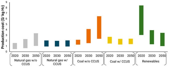
Figure 2.
Current and projected costs of hydrogen production technologies [12].
Electrolyzers use electricity to split water into hydrogen and oxygen. When the used electricity is sourced with renewables like wind, solar, or hydropower, the produced hydrogen is considered environmentally friendly, carbon-free and green. Although there are several potential renewable hydrogen production routes, the focus of this work is on water electrolysis since it is the most employed technology in the under-development valley projects [5]. There are three main investigated electrolysis technologies with the potential to be integrated into hydrogen valleys. Those technologies are AEL, PEMEL, and SOE. The operating principles of the different electrolyzer technologies are depicted in Figure 3. Additional advanced electrolysis technologies such as anion-exchange membrane [13], photo-electrochemical [14], plasma-assisted [15], microbial [16], acid-alkali [17] and bipolar membrane [18] exhibit promising results but are not widely investigated for their application into hydrogen valley scales [5].
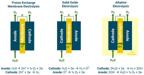
Figure 3.
Operating principles of proton exchange membrane, solid oxide, and alkaline electrolysis.
Electrolyzers are characterized by high modularity, multiple cells, and stacks that can be combined to achieve higher production capacities [19]. Table 1 presents the major expected technological progress that could increase the efficiency, overcome critical upscaling challenges, and decrease the associated costs of electrolyzers in the long term. More details on each technology can be found in Section 2.1, Section 2.2 and Section 2.3.

Table 1.
Present and projected performance indicators of electrolyzer technologies [20].
Apart from the electricity source, water is a critical feedstock of the process. Approximately 10–15 L of water are required per kg of produced hydrogen, which must fulfill certain requirements depending on the deployed technology [21]. For PEMEL, highly pure water is required with a minimum requirement of ASTM Type II deionized water (with a resistivity of >1 MΩ-cm), whereas Type I deionized water is preferred (>10 ΜΩ-cm). Alkaline electrolyzers do not require such purities; however, high purities are recommended for continuous and long-term operation. Apart from the resistivity, the total organic carbon has to be kept under <50 ppb and the sodium and chloride contents under <50 μg L−1. Highly pure water for electrolysis can be produced by a variety of purification techniques such as reverse osmosis, electrodialysis, and electro-deionization [22]. Seawater is also investigated as a potential water source for water-scarce regions and for regions with close proximity to the sea [23].
Oxygen is a by-product of water electrolysis; approximately 8 kg is produced per kg of hydrogen. Due to its high purity, oxygen has a high market value and can be used within the hydrogen valley in power production applications, steel plants, or sold externally to generate additional revenues (i.e., medical applications) [24,25]. The revenues of the by-product oxygen sales can decrease the associated hydrogen production costs and has been considered in several electrolysis-related techno-economic studies [26,27,28]. Waste heat from electrolysis can potentially also be utilized to increase the overall system efficiency [29] or used in other sectors such as district heating systems [30,31].
Section 2.1, Section 2.2 and Section 2.3 present the critical aspects of the three most mature and employed electrolysis technologies in hydrogen valleys, namely PEMEL, AEL, and SOEC.
2.1. Proton Exchange Membrane Electrolysis (PEMEL)
A PEMEL has a similar structure to a PEM fuel cell; it has two porous electrodes with a polymer membrane in between, whereas the operation principle is the reverse of the fuel cell operation [32]. Water is introduced at the anode where the oxygen evolution reaction (OER) is conducted, and water is split into protons and electrons [9]. The electrons travel through an external circuit, and protons travel through the membrane to the cathode, where they are recombined to form hydrogen through the hydrogen evolution reaction (HER) [33].
The reactions and the operating principles of the PEM electrolyzer are shown in Figure 3.
The solid polymer has to ensure high proton conductivity and relatively low resistances in the respective operation range. The two electrodes are directly mounted to the membrane constituting the membrane electrode assembly (MEA), which forms a single compact cell ensuring optimum contact between the different elements [34]. The most commonly used electrode materials are noble metals such as Pt and Pd at the cathode which exhibit excellent stability and activity but are expensive [35,36]. Recent research has focused on enhancing activity and durability as well as reducing costs through the investigation of alloys, nanoparticles, or reduction in precious metals loading [37,38,39]. For the OER at the anode, iridium oxide (IrO2) and ruthenium oxide (RuO2) remain the standard choices due to their high catalytic activity and stability under acidic conditions, which unfortunately exhibit high costs and scarcity [35]. However, efforts are ongoing to develop alternative catalysts that present high activity, durability, cost effectiveness, and electrolytic corrosion resistance, such as non-noble metal catalysts (i.e., transition metals, doped metals, or perovskite oxides) [40,41,42].
Typical PEMEL systems must include the power supply/voltage regulator, water supply (storage, supply, pump), water gas separator for hydrogen/oxygen, heat exchanger, controls and instrumentation, and oxygen storage tank along with the required safety protocols and devices [32].
PEMEL has great advantages in terms of high operating current densities, achieved efficiencies, and high hydrogen purity as well as compact design and small footprint [20,35,43]. It also presents fast responses (ramp up/down and start-up/shut-down) which are critical for the coupling with intermittent RES [35]. PEMEL can also offer the choice of pressurized operation (<70 bar), which dictates that the membrane must ensure mechanical stability and decrease gas permeation [20]. Pressurized operation can significantly decrease the associated compression requirements in the subsequent steps of the hydrogen valley if hydrogen is stored or used at elevated pressures. Some of the challenges associated with PEMEL are to reduce capital costs and increase the efficiency of the electrolyzer components such as catalysts, electrodes, and stack as well as increase the system’s lifetime [20].
2.2. Alkaline Electrolysis (AEL)
Alkaline electrolysis is a mature technology widely employed in industrial scales. It generally presents the lowest capital expenses among the different electrolyzer technologies and does not require critical raw materials compared to PEMEL [20]. AEL operates at low temperatures (30–80 °C) with an aqueous solution of NaOH/KOH as the liquid electrolyte with concentrations between 20 and 30% [36]. At the cathode, water is reduced by electrons to molecular hydrogen and hydroxide ions, whereas at the anode, hydroxide ions are oxidized to oxygen, water, and electrons (Figure 3). Alkaline electrolyzers are considered a robust and reliable technology, reaching in certain cases lifetimes of over 30 years [20], which renders them as a suitable technology for application within the hydrogen valley contexts [5].
Nickel-based catalysts dominate the field of alkaline electrolysis due to their cost effectiveness and reasonable catalytic performance [20]. Nickel is also often alloyed with Co or Mo to improve catalytic activity for the anode and cathode reactions, respectively [44,45,46]. For OER, nickel–iron-layered double hydroxides (NiFe-LDHs) and manganese are gaining attention that could offer a balance between cost, activity, and stability in alkaline conditions [47,48]. Recent advancements include the development of advanced diaphragm materials, such as polyphenylene sulfide fabric diaphragms, which improves ion conductivity and impurities resistance while reducing parasitic losses [20]. The efficiency of AEL systems typically ranges between 60 and 70% under normal conditions, but system integration with waste heat recovery or optimized process operation and control can improve this efficiency [49,50,51].
Apart from the power supply equipment, water gas separators, storage tanks, additional water supply, and electrolyte peripheral recirculation equipment are required within the system boundaries [20]. AEL systems require cheaper catalytic materials and present higher durability, which is a significant advantage compared to other electrolysis technologies [33,52]. Challenges associated with AEL on a stack level are the improvement of current densities up to 2–3 A/cm2 as well as the reduction in the diaphragm thickness that could improve the associated efficiency and reduce electricity consumption [20]. Leakages due to the use of liquid electrolyte are also observed in certain cases [53,54]. An additional challenge of alkaline electrolyzers is their lower response times and higher start-up/shut-down times, which could prove challenging when directly coupled with RES and processes that require regular ramp ups/downs [55]. To this end, alkaline electrolyzers could prove more suitable for baseload operations, whereas PEMEL can be used to cover peak and fast load changes.
2.3. Solid Oxide Electrolysis Cell (SOEC)
SOECs are high-temperature electrolyzers, operating typically between 700 and 800 °C. SOECs currently exhibit lower technological readiness levels compared to PEM and AEL but have gathered significant attention due to the higher potential efficiencies [56]. The higher temperature range reduces the anode/cathode overpotentials, and the favorable kinetics allow for the usage of low-cost electrode materials like nickel. In addition, available waste heat/thermal energy can be coupled with other heat-requiring processes [20], whereas reversible operation within a single device (electrolysis/fuel cell) is also possible [57]. The electrolyte, in this case, must present good ionic conductivity with negligible electronic conductivity. YSZ is the most widely utilized electrolyte material and can be operated in the range of 700–1000 °C [56]. For HER, nickel-based cermet materials, typically a combination of nickel and yttria-stabilized zirconia (Ni-YSZ), are widely used due to their good catalytic performance and thermal stability at high temperatures [20]. Efforts are being made to enhance these cermets by incorporating additional dopants such as cerium and gadolinium to reduce sintering and improve performance [58]. For OER, perovskite oxides like strontium-doped lanthanum manganite (LSM) and lanthanum strontium cobalt ferrite (LSCF) are standard choices, offering high ionic conductivity and stability under oxidizing conditions [20]. Emerging research is among others, exploring doped barium-based perovskites and novel mixed ionic-electronic conductors to optimize their activity and lifetime [59,60].
The solid ceramic electrolyte selectively conducts O2− ions, which pass through the electrolyte to generate molecular oxygen and electrons for the external circuit. The electrons that pass through the circuit are combined with steam at the cathode to produce hydrogen and oxygen ions (Figure 3).
The challenges of SOECs are associated with the lower lifetime, which is currently limited to 2–3 years compared to 10 years for PEMEL and 20 years for AEL [56]. Additional efforts are devoted to enhancing the performance and mitigating the degradation and aging to ensure the longer-term stability and continuous operation. Due to these factors, solid oxide electrolysis is the least preferred electrolysis technology in the under-development hydrogen valleys [5].
Significant effort is concentrated on the development and testing of suitable electrode materials, intermediate layers, and interconnectors that are cost efficient, can withstand high operating temperatures, and improve the durability of the process [56,61]. In this case, higher degradation rates are associated with thermochemical cycling due to regular ramp ups/downs and challenges associated with electrode contamination by silica (which is used as sealant) and other compounds used in piping, interconnects, and sealings [20]. Efforts to address these issues involve protective coatings [62,63] and alternative electrolyte formulations [56].
SOEC systems have the potential to achieve high total efficiencies particularly when integrated with waste heat recovery processes [64,65]. Case studies of interest for hydrogen valley applications involve the coupling with high waste heat availability processes such as nuclear [66,67] or solar [68,69]. These systems are also being increasingly tested for co-electrolysis, where both CO2 and H2O are converted into syngas, providing pathways for the synthesis of added-value products such as methane or methanol [70].
3. Hydrogen Storage
Hydrogen production should be complemented with cost-efficient storage systems to balance production and end-user demands. Suitable storage systems should enable seasonal storage and ensure the continuous supply of hydrogen to industrial applications. The critical challenge, in this case, is the volumetric energy density of hydrogen at atmospheric conditions. For the storage of specific energy amounts, hydrogen would require much larger volumes compared to natural gas and conventional liquid fuels. At normal conditions, hydrogen has a net heating value of 10.8 MJ/m3, whereas natural gas has an energy density about 4 times higher. Conventional liquid fuels have volumetric energy densities several orders of magnitude higher, approximately 3000 times higher compared to diesel and gasoline. Thus, hydrogen needs to be converted to an energy-dense form through an energy- and cost-efficient conversion route. Physical and chemical storage techniques could increase the volumetric energy density of hydrogen and be able to store larger amounts of energy within the same volume. Hydrogen can be stored in three main forms: (i) stored as gas or liquid with no chemical bonds to other materials, (ii) absorbed within a solid material, and (iii) chemically absorbed into chemical compounds (methanol, ammonia, and LOHC) [71]. From the different storage applications, solid hydrogen storage is currently at lower TRL and is not investigated in the under-development hydrogen valleys. Solid hydrogen storage includes the formation of solid-state hydrogen storage materials, such as metal hydrides (for instance magnesium hydride [72,73]) and metal–organic frameworks [74]. These solid materials can reversibly absorb and release hydrogen under specific pressure and temperature conditions, making them attractive for hydrogen storage applications. Table 2 presents an overview of the characteristics of the different hydrogen storage forms/mediums that are currently investigated for application in hydrogen valleys.
Table 2.
Characteristics and specifications of different hydrogen storage techniques [75,76,77,78,79,80,81].
Hydrogen end-use plays a significant role in the choice of hydrogen storage. Mobility applications require strict requirements regarding space and weight of the storage components, whereas industrial applications are not strict regarding the weight of the components [82,83]. Table 3 presents the state-of-the-art and relevant targets (set by the Clean Hydrogen JU) for critical KPIs regarding hydrogen for underground, aboveground, and on-board storage.
Table 3.
Key performance indicators and targets for hydrogen storage [84].
Hydrogen storage is inevitably linked to the transportation of hydrogen from the production site to the end-user. In a recent report by the Joint Research Center, hydrogen logistics were categorized into three phases: (i) packing (transforming hydrogen into a more compact form), (ii) transportation to the end-user site and (iii) unpacking (condition of hydrogen depending on the end-use) [85]. The choice between the different H2 packing forms should take into account the supply chain advantages of each form (related to storage and handling), the ability to use existing infrastructures, and the energy/cost requirements for the particular business case [86]. In this section, the characteristics and considerations for the different packing techniques are outlined, whereas Section 4 focuses on hydrogen transportation and unpacking.
3.1. Compressed Hydrogen
Hydrogen can be compressed with a compressor at storage pressure and then stored at dedicated vessels. There are different types of pressure vessels to which hydrogen can be stored depending also on the final end-use and operating pressures. Type I pressure vessels are fully metallic vessels, with typical pressures of 150–300 bar, and are mainly used to store hydrogen as industrial gas, whereas type IV pressure vessels are fully composite with pressures between 300 and 700 bar, mainly suited for stationary storage (HRS and on-board) [83,87,88]. The pressure tank storing hydrogen at elevated pressures must present high tensile strength, low density, and should not allow hydrogen diffusion through the material, which can cause embrittlement and eventually cracking [89]. Depending on the different used materials and properties, the capital costs of the storage tanks can vary, with Type IV vessels being the most expensive [88]. Those storage vessels are usually located above ground, whereas each of the equipment that is used for hydrogen storage and transportation (such as compressors, storage tanks, piping) should comply with the relevant international standards [90]. Hydrogen compression is less energy intensive than liquefaction, but approximately 10–15% of the contained energy is estimated to be used for this compression [91], depending also on the final storage pressure. Hydrogen can be compressed to the storage pressure using reciprocating diaphragm or centrifugal compressors. Ionic, electrochemical, and metal hydride compressors are also used but are at lower commercial levels for application at hydrogen valley scales [85].
Apart from vessels, large-scale gaseous hydrogen storage can be conducted in underground caverns, such as salt caverns, depleted natural gas reservoirs, or depleted oil wells [92]. Storage in salt caverns presents a viable option since it is already deployed in large scale for the storage of natural gas in Germany and the US [93]. Six salt caverns are currently used for hydrogen storage [94]; typical volumes can range from 100,000 to 1,000,000 m3, with maximum storage pressure of 200 bar [93,95]. A well-known example of hydrogen storage in salt caverns is in Teesside, UK, where hydrogen is stored at a depth of 400 m with a total volume of 210,000 m3 [96]. Underground salt caverns are an option to store hydrogen in large quantities and for long timeframes due to the stability and imperviousness of the salt cavern walls [95]. In salt caverns, hydrogen can be injected and withdrawn multiple times per year in contrast to the utilization of deep aquifers or depleted gas fields that can be utilized only for a particular number of cycles [92]. The criteria to which a salt cavern is suitable for hydrogen storage are related to its form, depth, and salt bed thickness as well as rock composition, distribution, and solubility [92]. Additional challenges are related to the hydrogen flow behavior in reservoirs, the geochemical and microbial–hydrogen interactions [97], the discharge rates, operating pressure range, and the purity of the recovered hydrogen [84]. Practical limitations for the usage of salt caverns as large-scale storage for hydrogen valleys are related to the location of the salt caverns. Only a few countries in the EU have the potential of underground storage, which will affect the logistics and transportation costs of the valley [98]. For instance, the industrial end-user may be located in a wider radius than the underground storage site, or the particular location might not be suitable for the installation of renewable energy plants or the hydrogen units. This has to take into account the additional costs for hydrogen distribution/transportation (Section 4). Apart from the stored volumes, the expected storage time is also a critical factor that could impact the economics of this process; underground storage is more suitable for seasonal storage, whereas above-ground vessels are suitable for shorter timeframes, acting as buffers or interim storage co-located with the electrolysis site [86].
3.2. Liquid Hydrogen
Hydrogen can be liquified at very low temperatures (between 20 K and 21 K), mainly through two different refrigeration loops (Brayton and Claude) [99]. The liquefaction process has a positive impact on the hydrogen energy density which is increased to 70.8 kg/m3 (8.5 MJ/L) and consequently reduces the required volume for storage and transportation [95]. Hydrogen liquefaction has been widely deployed by NASA for space applications starting from the 1960s [100]. NASA is also handling the largest spherical tank for liquefied hydrogen storage, with a volume of 3200 m3 [101]. Due to the very low involved temperatures, liquid hydrogen storage systems require efficient insulation through external protective jackets and inner pressure vessels [89]. For mobility applications, liquid hydrogen tanks are metallic double-walled vessels, with multilayer insulation, metallic foil layers separated by glass wool to ensure the proper vacuum of the systems and to avoid heat intrusion [83]. A challenge associated with this technology is the large amounts of energy required for liquefaction [93,95]. The main losses during this process are associated with heat exchangers, ortho-para hydrogen conversion, hydrogen purification, compression/expansion equipment, nitrogen liquefaction, and insulation [100,101,102]. Further research is devoted towards this direction to decrease the associated losses, facilitate the process scale-up, and also benefit the partial-load operations [103,104,105]. Another important aspect is the boil-off management of liquid hydrogen. Due to potential heating uptake from the surroundings, liquid hydrogen increases its temperature and evaporates, which could increase the system’s pressure and lead to safety issues. Pressure safety valves should be installed within the tanks to avoid pressure building and catastrophic damages/failures to the storage system [85]. The heating uptake depends on the ambient temperature, the heat transfer coefficient between the walls and the environment and the volume-surface ratio; spherical tanks usually present lower evaporation rates than cylindrical tanks. Cryogenic hydrogen leaks are also an issue, leading to air condensation and oxygen enrichment, forming potential flammable mixtures on ground levels due to the higher mass of liquid hydrogen compared to ambient air [106].
3.3. Methanol
Methanol is the simplest alcohol; it is water soluble, readily biodegradable, and has drawn attention as an energy and hydrogen carrier due to its high energy density (15.8 MJ/L). Methanol can be used directly as an industrial feedstock to produce other chemicals, as a transportation fuel, or as a hydrogen carrier that can be reformed to produce hydrogen on site [107]. Methanol is liquid at ambient conditions, rendering its storage and transportation easier compared to gaseous fuels. It can be easily transported through pipelines and stored in existing fueling stations, with low modifications to existing infrastructures [108]. Methanol can be stored in tanks with above-ground floating roofs and for lower scales, in floating baffle tanks. The storage of methanol is subjected to the same provisions as gasoline storage and should be grounded [107]. These characteristics of methanol would not require large investments for constructing storage, transportation, and refueling infrastructures compared to the use of hydrogen as transportation fuel. Particular attention should be paid to the toxicological properties of methanol; its handling and storage must comply with the relevant safety regulations [109].
Large-scale projects and plants are currently utilizing syngas for methanol synthesis as examined in a recent report by IRENA [110]. Fossil fuels are predominantly employed, with China relying on coal gasification and the rest of the world favoring natural gas reforming. In addition to the carbon source, an optimal addition ratio of hydrogen is also necessary. To minimize carbon emissions during the synthesis, it is crucial to obtain both the carbon feedstock and added hydrogen from renewable or waste sources. An attractive approach to generate renewable or low-carbon methanol involves utilizing carbon-containing off-gasses, such as captured CO2 or bio-CO2 [27,110,111,112]. In the case of hydrogen valleys, the added hydrogen can be derived from green sources, such as water electrolysis powered by RES. Producing methanol from renewable sources resembles the fossil-based approach and results in the production of methanol with comparable quality. However, the life-cycle emissions of green methanol are substantially reduced, presenting a promising route to reduce the carbon footprint of methanol synthesis [113]. Green methanol production currently accounts for >1% of the total production, with primary challenges linked to the higher production expenses associated with this technology and the carbon/hydrogen feedstocks. The cost of the carbon feedstock depends on its source, whether it is derived from CO2 capture, direct air capture, or industrial off-gasses, as well as the associated energy required for purification and compression. However, the majority of the expenses are associated with the production of green hydrogen via electrolysis, with the primary cost factors being the electricity and electrolyzer costs [27].
3.4. Ammonia
Due to its favorable properties, energy density (12.7 MJ/L), and liquid form at atmospheric conditions, ammonia is widely investigated as a hydrogen carrier for the storage and transportation of hydrogen at large distances. Another advantage of ammonia is that it does not contain any carbon within its molecule, rendering its utilization carbon-free. However, ammonia is already produced at large scale using fossil-based resources with approximately 183 Mt produced in 2020, mostly from natural gas (72%), coal (22%), and oil (5%) with several renewable ammonia projects being announced globally [101]. Ammonia is widely produced through the Haber–Bosch process, where hydrogen and nitrogen are reacting at elevated pressures and temperatures (400–650 °C and 200–400 bar) over multi-bed reactors filled with iron-based catalysts [114,115]. Nitrogen is usually derived from an air separation unit that consumes electricity, whereas hydrogen in this case can be renewable and stems from the valley operations. The main challenges are related to the costs of producing renewable hydrogen, the feasibility of globally switching to renewable ammonia production processes, and the ramp-up/down flexibility of the production system to different fluctuations of the hydrogen production supply [101,116].
Hydrogen can be stored in the form of ammonia and avoid the high energy penalty of hydrogen liquefaction. Ammonia can be liquefied at −33 °C at atmospheric pressure or at 20 °C under 7.5 bar pressure [88]. For large quantities, the economically favorable option is low temperature storage, whereas non-refrigerated, pressurized storage is suitable for lower quantities. Low temperature storage is conducted at −33 °C at 1.1–1.2 bar for capacities between 4500 and 45,000 t of ammonia, whereas non-refrigerated storage is conducted at 20–25 °C at 16–18 bar and is preferrable for capacities of <1500 t. Ammonia is considered a viable energy storage option for longer timeframes compared to pure hydrogen storage [80]. After storage, ammonia can be either cracked to receive hydrogen in pure form or directly used, for instance in energy or synthesis applications. The ammonia cracking process is an additional energy loss that further reduces the system efficiency; it is estimated that 14% of ammonia is used in the cracking process for heating purposes. To this end, for power production applications, direct ammonia combustion is preferred to avoid the additional cracking step. Furthermore, ammonia spills and leakages should also be taken into account, since ammonia can form aerosols in the atmosphere as well as affect the soil and water quality if released [80,117].
3.5. Liquid Organic Hydrogen Carriers
Liquid organic hydrogen carriers are hydrogen-rich aromatic compounds that can store and transport hydrogen in a liquid form with increased volumetric densities. These compounds react with hydrogen (hydrogenation), are transported in liquid form, and are dehydrogenated at the final destination to release the contained hydrogen. They are used as alternatives to compressed or liquid hydrogen, offering advantages in terms of safety, storage, and handling [118]. One of the advantages of LOHCs is their ability to store and transport hydrogen at ambient conditions, eliminating the need for cost- and energy-intensive compression/liquefaction processes. LOHCs also offer higher energy densities compared to compressed gas, allowing for increased storage capacity and favorable safety characteristics. LOHCs do not require high-pressure storage vessels, reducing the risk of leaks or explosions and do not involve any boil-off losses compared to liquid hydrogen storage and transportation [119]. Additionally, LOHCs are not flammable or explosive under normal conditions, further enhancing their safety profile.
LOHCs typically consist of a hydrogen-rich organic compound, often an aromatic or cyclic hydrocarbon, that can reversibly bind and release hydrogen through chemical reactions. These compounds have the ability to absorb hydrogen at relatively low pressures and temperatures. The process of storing and releasing hydrogen using LOHCs involves two main steps: hydrogenation and dehydrogenation. During the hydrogenation step, the LOHC compound reacts with hydrogen to form a hydrogenated LOHC, which allows for the chemical binding of hydrogen. When the stored hydrogen is needed at the end-user site, the dehydrogenation step takes place, which is an endothermic process. The hydrogenated LOHC is subjected to specific conditions, such as elevated temperatures or catalyst usage, which trigger the hydrogen release. For the case where an inexpensive heat source is locally available, the process efficiency can be improved, and the costs can be further reduced [120]. The selection of suitable LOHC compounds for the hydrogen valley context depends on several parameters such as the price and production costs, the technological maturity, the available infrastructure, and the potential availability of the heat source for hydrogen release [119]. Commonly investigated LOHC compounds include dibenzyltoluene [119,121], toluene [121,122], benzene [123,124], and naphthalene [125,126]. For the case of toluene/methylcyclohexane, the hydrogenation/dehydrogenation reactions are as follows [127]:
C6H5CH3 + 3H2 → C6H11CH3 ΔH0298K = −204.8 kJ/mol
C6H11CH3 → C6H5CH3 + 3H2 ΔH0298K = +204.8 kJ/mol
Many LOHCs are oil derivatives, meaning that there is an available infrastructure for storage, transportation, and trading [128]. However, the production of LOHCs from fossil resources would deteriorate the environmental footprint of this option; to this end, production from bio-resources is investigated [75]. In general, there are also flammability, health, and environmental risks related to the use of benzene, substituted benzenes, and aromatic molecules [129]. Furthermore, the dehydrogenation step is critical during the utilization cycle, where additional side reactions could occur, resulting in lower amounts of produced hydrogen and the need for additional purification steps to achieve certain purity levels [121]. The dehydrogenation reaction is also endothermic, with heat requirements that could amount to 30–40% of the contained hydrogen energy. Assuming there are no side reactions, the dehydrogenation heat is the opposite of hydrogenation, and the produced heat is at medium temperature (150–250 °C) [101]. The recovered hydrogen is also at atmospheric pressures, meaning that lower energy demands are required for the packing and transportation of hydrogen. On the other hand, if high-pressure applications are required in the hydrogen valley context (such as for refueling or industrial applications), an additional compression step is required. Ongoing research aims to optimize the potential selection of LOHCs, increase the efficiency of the hydrogenation and dehydrogenation processes, and explore their integration into existing infrastructures [128].
4. Hydrogen Transmission and Distribution
After hydrogen is produced and stored at the required conditions and forms, it is transported from the production site to the end-user. The scope of hydrogen valleys is to gather the complete hydrogen value chain within a defined region; however, additional costs are required to transport and distribute hydrogen within the valley operations. The low volumetric and energy densities of hydrogen at atmospheric conditions necessitate its conversion into an energy-dense and compact form that can be easily transported with existing infrastructures or after minimum modifications. Hydrogen can be physically stored in compressed gaseous or liquid form and/or chemically converted to ammonia, methanol, or liquid organic hydrogen carriers (Section 3). For the case of hydrogen (CH2 or LH2), hydrogen is transported to the end-location and used without requiring further chemical conversions (Figure 4). For the case of chemical carriers (methanol and ammonia), the transportation cycle involves: (i) the hydrogenation phase (production of the chemical carrier), (ii) transportation, and (iii) dehydrogenation (in cases where pure hydrogen will be used) or direct usage of the carrier [120]. For the case of LOHC, it involves transportation to the end-user site, dehydrogenation to recover the produced hydrogen at the end-user site, and finally transportation of the dehydrogenated form back to the hydrogen production site to be further hydrogenated.
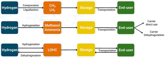
Figure 4.
Operation principles of different hydrogen and hydrogen-derivative storage and transportation options.
Hydrogen can be transported to the end-location via pipelines [54,130,131,132,133,134,135,136,137], trucks [54,120,130,132,133,134,135,136,137,138,139,140,141], and ships [134,136,137,142,143]. Transportation by rail is also an inland transportation option with similar efficiency as ships but with lower capacity than pipelines and is therefore not further investigated in this study [101]. The choice between the different hydrogen transportation/distribution options depends on the end-use (i.e., industrial use or HRS supply), distance between production and end-users, inland or sea transportation, hydrogen amounts/capacities, and on the already available infrastructures [85]. In particular, for the utilization of hydrogen in refueling stations, the choice between gaseous or liquid hydrogen distribution by trucks/trailers and the associated costs also depend on the capacity of the stations and the market demand for hydrogen as well as risk/safety factors [138,139,140]. Centralized or non-centralized hydrogen production, especially for HRS supply, is also the scope of research in several works. For limited production capacities, on-site hydrogen production is preferable compared to centralized production and transportation to the different end-user sites [138]. In principle, gaseous or LH2 are suitable for transportation in shorter distances, whereas chemical carriers or LOHC are suitable for larger distances such as overseas transportation [85,142]. Overall, there is no globally optimum option to transport hydrogen from one location to another; each case presents specific characteristics [134]. A recent report by IRENA presented a roadmap for the transportation costs of hydrogen based on the covered distance and transported volumes (Figure 5) [101]. In addition, hydrogen transportation still needs to be proven in large scales and in the global trading context [144]. Nevertheless, this work is focused on hydrogen transportation and distribution within the valley boundaries, and to this end, overseas transportation is not within the scope of this work.
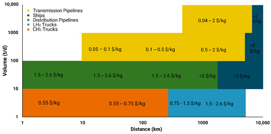
Figure 5.
Range of costs of different transportation options based on distance and volume [101].
4.1. Pipelines for Hydrogen Transmission and Distribution
Hydrogen pipelines can provide an efficient transportation option to move compressed gaseous hydrogen from a fixed location to another (point-to-point) [54,130,131,132,133,134,135,136]. To transport hydrogen with pipelines, hydrogen is compressed to the pipeline pressure (or higher), which is generally higher than the electrolysis pressure. As with natural gas pipelines, the gas must be recompressed at certain compression stations before it reaches its final destination. There are already existing hydrogen pipelines which are mainly operated by industrial users such as Air Liquide, Air Products, and Linde [145]. In Europe there are more than 1000 km of hydrogen pipelines that serve industrial users [84]. Pipelines could be especially suitable for large-distance, land transportation of hydrogen to industrial, high-capacity end-users [85]. There are three main ways of transporting hydrogen via pipelines: (i) modifying existing natural gas pipelines to transport hydrogen, (ii) blend hydrogen with natural gas in existing pipelines, and (iii) build new short- or long-distance hydrogen pipelines. Overall, it is estimated that the modification costs of existing natural gas pipelines are lower than the cost of new constructions [131]. Based on a recent report by IRENA, newly constructed hydrogen pipelines could be economically attractive for transportation of up to 4000 km, whereas repurposed natural gas pipelines can extend this distance up to 8000 km [101]. There are no fixed operating pressure ranges for hydrogen pipelines; currently operating industrial pipelines have upper limits of 100 bar, with natural gas transmission pipelines in Europe operating between 40 and 80 bar. The hydrogen pipeline can be constructed from materials including plastics, metals, and composite materials [85] that should comply with the relevant standards [90] to avoid embrittlement and safety issues [146]. Again, in this case, the hydrogen capacity and distance between production/consumption points are crucial for the economic and environmental performances of the process [134]. For newly constructed pipelines, increased attention should be paid so as to not oversize the pipeline capacity, which would result in increased CAPEX, whereas under-sizing would result in a subsequent loss of potential revenues. Future-proofing during the design and planning phase could account for potential increased demands and risks in the future.
Table 4 presents the state of the art of current hydrogen pipelines and the relevant mid-term targets set by the Clean Hydrogen JU, regarding the capital expenses, transmission pressure, and hydrogen leakages [84].
Table 4.
Key performance indicators and targets for hydrogen pipelines [84].
Compressed hydrogen is the main hydrogen form investigated for pipeline transportation. Ammonia is also investigated as a potential transportation medium for pipelines [133,136,137]. A 4950 km ammonia pipeline is already operating in the USA, which is transporting ammonia from a central location to the end-users (mainly farmers) [147]. LOHCs are also proposed as potential carriers for pipeline transportation. In this case, the need for double pipelines to transport the hydrogenated and dehydrogenated form between the two locations will result in overall higher capital expenses [85]. The challenges of pipelines are associated with their lower flexibility compared to other modes of transportation and the difficulties of retrofitting as well as the risk of over-/underestimating demands. Pipelines will also require extensive permitting and licensing procedures (especially prevalent for interregional and cross-country transportation), whereas additional distribution pipelines will be required for smaller consumers that are not along the pipeline corridor [144].
4.2. Trucks for Hydrogen Distribution
Hydrogen can be transported in different forms using dedicated tube and trailer trucks. For the case of transporting gaseous hydrogen [54,130,132,133,134,135,136,138,139,141], CH2 is loaded onto high-pressure-resistant containers such as tube trailers, which are already used in multiple commercial applications, and transported to the final destination [132]. For the case of hydrogen that is used in mobility applications, it is unloaded in the HRS that also includes compressors, high-pressure storage, and dispensers [141]. Multiple-element gas containers are used for road transportation purposes, which can be either metallic or composite cylinders. Metallic cylinders have been extensively used for transportation up to 300 bar, whereas composite cylinders are more expensive but can store hydrogen at higher pressures (<500 bars), leading to higher amounts of transported hydrogen [85]. A strategic challenge is to develop trailers that can store and transport hydrogen at 700 bar which will consequently increase the amount of transported hydrogen and reduce specific costs. Hydrogen can also be transported in liquid form through dedicated trucks [54,132,133,134,135,136,138,139,140], which could be integrated or have separable containers for storage. In this case, the LH2 tanks must be adequately insulated to increase volumetric efficiency and reduce heat input as well as have special structures to withstand the weight pressure [148]. Trucks for the transportation of CH2 usually exhibit lower capacities compared to cryogenic tanks that carry LH2. This implies that in the case of gaseous hydrogen, more routes or trucks are required to transport the same amount of hydrogen to the end-user, leading to higher overall costs and environmental impact [85,138]. Table 5 presents the state of the art of hydrogen tube/LH2 tank trailers and the relevant mid-term targets set by the Clean Hydrogen JU [84].
Table 5.
Key performance indicators and targets for hydrogen trucks (set by the Clean Hydrogen JU) [84].
In general, for lower distances and capacities, it is estimated that CH2 trailers are more cost competitive than LH2 [135,141]. Apart from CH2 and LH2 trucks, ammonia, methanol, and LOHC trucks are also investigated [120,132,136,137]. For the case of LOHC, the trucks can transport the dehydrogenated form back to the production location, to be hydrogenated again and carry the produced hydrogen within the transported LOHC molecule [120]. In principle, trucks are more suitable for hydrogen distribution that involves transporting and distributing hydrogen from a central facility to a city or multiple HRS that require regular re-supply [134].
5. Hydrogen End-Uses
Hydrogen can provide an efficient way to integrate renewable energy into hard-to-abate sectors, such as mobility, industry, and power [149]. The next sections present an overview of hydrogen use in those sectors, critical thoughts regarding the maturity of those technologies, and the path towards full commercialization.
5.1. Pipelines for Hydrogen Transmission and Distribution
The mobility sector contributed to a quarter of the worldwide energy-related CO2 emissions and is projected to increase in the coming years due to population growth, expansion of tourism, and rise in e-commerce [150]. Due to its clean combustion characteristics, hydrogen is investigated as green fuel in a variety of road applications such as cars, trucks, buses, and forklifts. Hydrogen use in each transportation mode presents different TRLs and maturities. Forklifts and cars currently exhibit the highest TRL and are commercially available [151]. Fuel cell trains also exhibit high TRL and can achieve significant improvements in terms of energy efficiencies, energy demand decrease, and carbon emissions reductions compared to diesel trains [152]. Finally, the marine sector is also a potential application field for hydrogen and hydrogen carriers. Hydrogen is also investigated as aviation fuel, but there are critical challenges related to aircraft and engine design, hydrogen storage, and its related infrastructure [153,154].
In general, fuel cell electric vehicles (FCEVs) use a similar propulsion system with battery vehicles. In this case, energy is stored in the form of hydrogen in dedicated pressure tanks (350/700 bar). Hydrogen is then used in a fuel cell to produce electricity, which is then driving an electric motor to mobilize the vehicle. The FCEV is often combined with a battery pack as an additional power source to increase the efficiency and autonomy of the vehicle. The additional units are the water/heat management system, air supply system, and power control unit [155]. FCEVs offer longer driving ranges (<600 km) and shorter refueling times (<10 min) compared to battery electric vehicles, making them also suitable for longer-distance trips [156]. Theoretically, battery vehicles have higher energy efficiencies and are more mature, but the external environmental conditions and the battery weight could influence the driving autonomy of the vehicle [155]. Compared to a gasoline engine, FCEVs present higher energy efficiencies, approximately 40–60% of the fuel energy compared to 20% of a gasoline vehicle [156]. In addition, they generate zero emissions, offering noiseless driving experience with water vapor as the only by-product. Commercially available vehicles include the Toyota Mirai, Honda Clarity, and Hyundai Nexo (Table 6) [155]. A study conducted by Roland Berger estimates that over 1 million cars will be deployed in Europe by 2030, meaning that significant progress and cost reductions are expected within this decade [151].
Table 6.
Characteristics of fuel cell electric vehicles.
FC buses are increasingly being adopted in public transportation as they provide zero-emission operation and have longer autonomy compared to battery-powered buses. Since most are operated by public bodies, they are following predictable routes and have predictable refueling patterns [155]. By the end of 2020, approximately 5648 fuel cell buses were used worldwide, with 97% of them located in Asia [160]. For light- and medium-duty trucks, fuel cells can provide an efficient solution for inner- and inter-city distribution of goods. They could provide a zero-pollution and noiseless solution within cities, whereas the short refueling times can prove a positive aspect for the supply logistics [155]. On the other hand, the replacement of heavy-duty diesel trucks by fuel cell trucks is shifted towards the long term since there are challenges related to the high vehicle and hydrogen costs, the required volumes to carry heavy weights over long distances, and the limited refueling infrastructure [161].
Hydrogen usage is also investigated as fuel for the maritime sector, which has set ambitious targets for reducing emissions and improving energy efficiencies [162]. Hydrogen can be stored on-board in different forms and then used in fuel cells to power propulsion as well the respective hotel loads of the ship [163]. PEMFCs and SOFCs are considered the most promising for marine applications [164,165]. Marinized fuel cells, however, do not exhibit the same technological advancements as land-based technologies and must be resistant against the highly corrosive sea conditions, tilting, and related vibration conditions during the ship voyage. Another aspect is the on-board storage of hydrogen since there are restrictions regarding the weight and volumes that storage tanks can occupy while also complying with the relevant safety standards [165]. Table 7 presents the current status and future targets set by the Clean Hydrogen JU regarding marine fuel cell systems.
Table 7.
Key performance indicators and targets for marine fuel cell systems [84].
Hydrogen has been demonstrated in several international projects and in different vessel types [166,167]. The connection of hydrogen valleys to the shipping industry, imposes that ports also possess the relevant hydrogen infrastructure for refueling and fuel storage [168,169]. The development of dedicated hydrogen terminals or the co-existence of hydrogen and LNG terminals is within the prerequisites for the wider implementation of the hydrogen economy [84].
Fuel cell forklifts are currently at high TRL and are commercially available since they mainly involve lower required technology requirements and infrastructures. The maximum output power of a forklift is estimated to be one-tenth of passenger vehicles, and since they are mostly used in limited and restricted areas, the operation and refueling patterns are predictable. Furthermore, they can be used safely in enclosed industrial facilities (such as food and beverage industries) since they do not emit harmful emissions [155]. Hydrogen can also be utilized in rail vehicles to power the motors and/or the auxiliaries and is currently exhibiting high TRL. Fuel cells are used to generate power from hydrogen which can be coupled with energy storage units such as batteries [170]. High efficiency, noiseless operation and no emissions are some of the advantages of hydrogen-powered trains, whereas the on-board hydrogen storage and the refueling infrastructure are critical limitations [171].
Overall, the development of a reliable and widely accessible refueling infrastructure is a prerequisite for the widespread adoption of hydrogen in mobility applications. For instance, hydrogen vehicles must be refueled in stations adhering to necessary standards that will, among others, ensure the safe and timely refueling of the vehicle [172]. According to the H2stations database, there were 814 refueling stations in operation in 2022 worldwide, with significant progress taking place in the past decade (Figure 6) [173]. It is estimated that approximately 3700 refueling stations will be constructed and operated by 2030 in Europe, illustrating major infrastructure investments towards this direction [155]. For the case of Germany, there are approximately 100 open refueling stations, with many more currently planned or constructed [174].
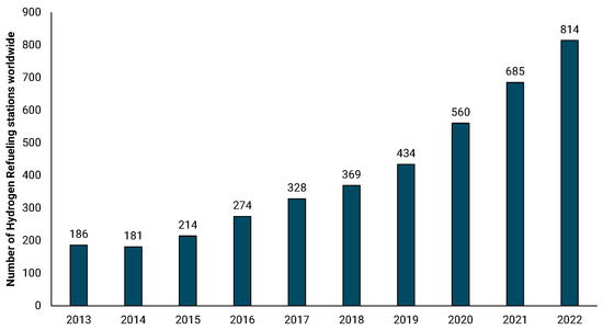
Figure 6.
Number of hydrogen refueling stations worldwide [173].
A refueling station includes equipment such as compressors, storage tanks, cooling units, safety equipment, mechanical/electrical equipment, and dispensers [175]. Hydrogen refueling stations can be categorized as “off-site”, where hydrogen is produced outside and transported to the refueling station, or “on-site”, where hydrogen is produced inside the battery limits of the station. For the case of off-site refueling stations, which is mainly the case for hydrogen valleys integration, hydrogen supply chain optimization is necessary to reduce costs and the respective environmental footprint [140]. On-site hydrogen production stations have higher capital expenses than off-site HRS [175], but do not require additional distribution costs. Furthermore, HRS can also be distinguished on whether hydrogen is stored as liquid or gas [172]. The initial storage pressure, filling rates, inlet temperature, cylinder dimensions/types, and ambient conditions are parameters that affect the design of a refueling station and the respective supply plan [176,177].
Overall, critical challenges related to the use of hydrogen in road mobility applications include the lack of established hydrogen distribution and refueling infrastructures as well as the related approval and licensing processes [156,178]. FC vehicles and trucks currently exhibit higher purchase costs and consequently lead to higher cost of ownership compared to battery vehicles. However, the costs are expected to drop significantly in the future through dedicated policy support and technology developments [179]. In addition, there are fundamental misconceptions regarding hydrogen safety that must be resolved for wider adoption and social acceptance [180]. The earlier adoption of hydrogen vehicles is associated with the income, education, and social status of the citizen [139]. Finally, for wider market penetration of hydrogen in mobility applications, the low price, fuel availability, and mass production of FC vehicles are prerequisites.
5.2. Energy Production
The conversion of renewable energy to hydrogen and its subsequent use for electricity production could result in a total cycle efficiency of less than 40%. The utilization of hydrogen for energy production purposes is particularly beneficial under certain circumstances, and, in particular, when using it as a long-term, renewable energy storage medium. To this end, hydrogen production and storage could compensate, for instance, for the lack of sun radiation at night or low wind speed conditions. Hydrogen can help improve grid stability and the amount of renewables that can be integrated into the grid since the excess energy will not be curtailed but harnessed and stored. Optimum hydrogen storage design and sizing is particularly important for hydrogen valleys that are powered by RES. In this section three main ways of electricity production will be analyzed, namely gas-fired power plants, injection in the natural gas grid, and stationary fuel cells.
Gas-fired power plants utilize natural gas to produce electricity, and the total efficiency of a combined cycle power plant can range from 50 to 60% [85]. However, due to the current climate mitigation efforts and geopolitical events, there is an urgent need to reduce carbon emissions and switch to sustainable power-producing solutions. A strong advantage of gas turbines is that they have higher fuel flexibility compared to fuel cells; existing natural gas-combined cycles can be retrofitted to use hydrogen, reducing further investment requirements. Apart from pure hydrogen use in gas turbines, pre-combustion CO2 capture is investigated as a potential solution; this can be conducted through natural gas reforming to produce hydrogen that will then be used in the power plant [181]. Both solutions require that existing power plants must be retrofitted to operate on hydrogen and/or develop new power plant designs that can be easily retrofitted and be hydrogen-ready in the future. Up to now, the utilization of a 30% hydrogen–natural gas mixture is possible without retrofitting requirements [182]; a percentage of that could be higher, depending on the specific gas turbine class and type. Hydrogen has different properties compared to natural gas; it is a smaller molecule, with different energy density and combustion characteristics and can cause embrittlement to steel pipes and equipment, which needs to be considered during retrofitting. In particular, fuel pipes with larger diameters are required which in turn need additional space in the plant. The most significant change would be adapting the gas turbine and the combustion chamber to use H2. The flame velocity and the reactivity of hydrogen as a fuel are much higher than natural gas, requiring a flashback-proof burner design. Furthermore, a slightly higher flame temperature means that NOx emissions will rise. Nevertheless, apart from retrofitting existing plants, the newly constructed gas-fired power plants should take into account the momentum of hydrogen as an energy vector and be prepared for a “switch-to-hydrogen” scenario [181,182].
An alternative approach to hydrogen integration is through the existing natural gas grid. Given the limited hydrogen transportation infrastructure, the existing natural gas grid could function as a storage medium for renewable energy in the form of hydrogen [183], enabling efficient transport and distribution to both small- and large-scale consumers with minimum losses (0.7% for gas grid compared to 2–6% for electricity grids) [184]. In particular, the EU is proceeding with significant investments to retrofit the existing natural gas pipeline network into a hydrogen-ready network that can absorb significant quantities of renewable hydrogen [185]. In the EU it is envisaged that natural gas will be progressively substituted by other clean gasses. Apart from the logistics, grid injection has been proposed as an option to reduce the associated GHG emissions of the gas end-use [186]. But several obstacles need to be overcome before this approach can be widely adopted. These challenges encompass issues such as determining the maximum allowable blending limits for specific end-users, addressing safety and technical concerns (such as embrittlement, gas leakages, and accurate gas measurements), economic considerations, and the absence of uniform national and international regulation frameworks [186,187,188,189]. According to a recent report from the EU, the current gas grid can accommodate hydrogen blending up to 10% by volume, but with minimal modifications, this limit can be increased to 20% [185]. The exact determination of the upper limits for blending would require a detailed analysis on the used equipment and specifications across the complete value chain: from the pipeline and storage tank to the end-user. Extensive research efforts are undertaken in terms of pipeline materials to avoid degradation and corrosion effects [190], whereas the injection also affects the thermodynamic properties of the gas–H2 blend [133,191]. Based on the current regulations, the natural gas quality must comply with the lower and upper limits regarding its Wobbe index, gross calorific value, and relative density of the transported gas. The gaseous mixture can be utilized in its blended form for commercial industrial or residential applications and/or recover the hydrogen as well as used in its pure form through hydrogen recovery techniques such as pressure swing adsorption and membrane or electrochemical compression [192,193,194,195].
Finally, hydrogen can be utilized in stationary FCs for energy production. A fuel cell is an electrochemical device that converts the chemical energy of a fuel into electricity and heat through electrochemical reactions. Stationary fuel cells can also act as back-up units or off-grid power production solutions for remote and off-grid areas. When hydrogen is the fuel, electricity, water, and heat are the only products, resulting in a completely carbon-free form of energy production. There are several available fuel cell technologies that, among others, differ on the operating temperatures, electrolytes, anode/cathode reactions, each with different TRLs, efficiencies, characteristics, and costs [196]. The most common FC technologies that are currently investigated for stationary applications are PEMFC and SOFC [197]. Based on the current state of the art, fuel cells operate with an electrical efficiency of 40–60% (depending on the applied technology) [196], whereas for cases of combined heat and power, the total efficiency can exceed over 80% [198]. The main sectors to which stationary FCs can be applied to include micro-CHP, large stationary applications, uninterruptible power supply, and integrated power supply [198]. An important feature of FCs is that they are modular, indicating that several stacks can be combined to provide the necessary power. In contrast to the application of FCs for transportation purposes, for stationary applications, there are no strict limitations regarding the weight and space occupancy of the FC system components [91]. Overall, significant technological advancements have been achieved in the past years, but progress is still needed to further reduce the investment costs, durability, and lifetime of fuel cells [197,198]. Table 8 presents the current status and future targets set by the Clean Hydrogen JU regarding stationary PEMFC and SOFC systems.
Table 8.
Key performance indicators and targets for stationary PEMFC and SOFC system [84].
A crucial factor for the integration of stationary fuel cells into hydrogen valleys that are powered by renewable energy sources is the operation flexibility of the system. Due to the intermittency of RES and depending on the load demands as well as economic factors, fuel cells have to present short times for the system startup/shutdown as well as for the ramp-up/down at diverse operating conditions [199,200,201]. Another technology, which is at a lower commercial level but can offer potential advantages in terms of fuel flexibility, roundtrip efficiencies, and power densities, is reversible solid oxide cells (rSOCs). rSOCs can switch between electrolysis and fuel cell mode operation within a single device depending on the electricity prices, RES availability, and load demands, thus reducing the need for two different devices [57,202]. In addition, the waste heat from the rSOC can also be valorized within an integrated plant concept [202,203].
5.3. Industry
The term energy-intensive industries refers to sectors that are high energy users and carbon emitters. Those are mainly the iron and steel, chemicals, refining, and cement industries. The decarbonization of those industries presents a challenge since they need to cut carbon emissions and reduce the usage of fossil resources as well as stay competitive in the global market. This can be achieved by increasing the efficiency of existing processes and by integrating renewable energy and/or green carbon molecules into their operation [204]. Renewable hydrogen, in this case, can provide an alternative to fossil resources and fossil-based hydrogen that are already used in those industries. A crucial point for renewable hydrogen integration in industrial processes is that they operate continuously. Hydrogen production powered by renewable electricity necessitates the design of suitable energy and hydrogen storage systems to ensure its uninterrupted and continuous supply to the industry. An additional aspect is that in certain cases, there is an existing demand for hydrogen which is covered by fossil resources and can be replaced by renewable hydrogen (for example in refineries), whereas other sectors require the development and establishment of novel processes and hydrogen demands (such as hydrogen-based steelmaking).
The iron and steel industry is one of the most energy- and carbon-intensive sectors globally, contributing to 27% of the total industrial CO2 emissions and 4–5% of the overall anthropogenic CO2 emissions [205]. As the global demand for steel is projected to increase until 2060 [206], it is necessary to adopt decarbonization technologies to align with the Paris Agreement goals [207]. Steel production in Europe is mainly divided between two routes: (i) integrated steelmaking with blast furnace in combination with the basic oxygen furnace and (ii) electric arc furnace routes, typically where additional materials such as direct reduced iron (DRI) may be added [208]. Renewable hydrogen emerges as a key component to this end, with mainly two approaches being mostly applied within the two steelmaking routes [209,210]. The first approach necessitates the development of novel production processes that deviate from the existing processes but is very promising in terms of reducing carbon emissions. The focus is on using hydrogen to produce DRI, and then processing it into an electric arc furnace to produce steel. This process entails potential for reducing/substituting coke/carbon monoxide with renewable hydrogen as a reducing agent in the steelmaking process [211,212]. Figure 7 shows the potential integration of renewable hydrogen and/or hydrogen valleys into steelworks using this approach. This approach takes advantage of the higher calorific value, lower density, and faster reduction rates of hydrogen compared to CO and could prove promising in reducing the associated GHG emissions [213]. Implementing this approach would need substantial subsidies, extensive infrastructure modifications, and large amounts of electricity [208,214]. According to a recent study, a complete shift in the European steel sector to hydrogen-based production would necessitate an annual electricity consumption of 400–500 TWh [215]. To fully decarbonize the annual steel production of Germany (42 Mt), it would require approximately 100 TWh of renewable energy [216]. Other issues involve the maturity, production costs, and scaling-up of the hydrogen-based processes compared to the conventional process [213,216].
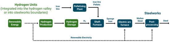
Figure 7.
Integration of renewable hydrogen and hydrogen valleys with steelworks through the DRI process.
The second approach involves the complete conversion of steelworks off-gasses into added-value products like methane and methanol (Figure 8) [111,217]. In contrast to the first approach, the production of methane and methanol from syngas is already deployed in large-scale facilities [110,218]. Steelwork off-gasses, including blast furnace gas, coke oven gas, and basic oxygen furnace gas, are generated at various stages of steel production and are typically used internally within the steelmaking process or for power generation purposes. Any excess gasses are stored in gasholders and in many cases flared with detrimental environmental impact. This approach could utilize those gasses to produce valuable chemicals that have significant market value, such as methanol [217,219] or gas that can be used internally for power/heat generation (i.e., methane) [220,221]. This method necessitates the addition of renewable hydrogen, since the hydrogen content in those off-gasses is insufficient for their synthesis. Critical issues in this approach are the composition of the gasses (high inert contents) and the production costs that are mainly associated with the electricity to produce renewable hydrogen [27].
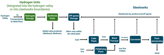
Figure 8.
Integration of renewable hydrogen and hydrogen valleys with steelworks for the production of added-value products.
In 2015, the refining sector was responsible for emitting 2 Gt of CO2, which is projected to reach 2.8 Gt per year in 2050 [222]. Crude oil remains the dominant commodity in the energy landscape and is expected to maintain this position in the coming decades. The large-scale production, cost effectiveness, and availability of high-density fuels have positioned crude oil as an essential component for the transportation and consumer sectors [223]. With the ongoing energy transition, petrochemical industries are facing pressures to revise their policies and reduce carbon emissions. Refineries rely on large quantities of hydrogen, which are primarily generated internally from hydrocarbon cracking and natural gas reforming or purchased from external suppliers. It is estimated that up to 50% of the hydrogen used is externally sourced through natural gas reforming, while the remaining is produced from internal processes. The substitution of externally sourced, fossil-based hydrogen with renewable hydrogen is technically viable and offers a reliable option for reducing both direct and indirect carbon emissions [224,225]. The second approach involves integrating biomass or waste carbon feedstocks into refinery processes, following their prior upgrading through hydroprocessing using renewable hydrogen (Figure 9). This method offers an opportunity to make use of current infrastructures and capacities without deviating from established production processes and replaces fossil- with renewable-carbon [226]. As an example, through the pyrolysis route, biomass is thermochemically converted to bio-oil. Given the high oxygen and water content of bio-oil, it requires further upgrading in the hydrotreatment unit using renewable hydrogen. The higher value bio-intermediate is finally inserted into refinery operations, such as in the FCC or hydrotreatment units. A critical factor is that the intermediate product must be compatible with both the respective refinery operation and the petroleum distillate/feedstock processed in that unit [227,228]. The quantities of the required renewable hydrogen will significant impact the economic feasibility of the proposed scheme and its further establishment [26].
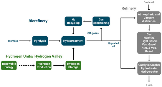
Figure 9.
Indicative biorefinery concept, integrating biomass and renewable hydrogen into refinery operations [26].
Regarding the chemical industry, hydrogen is an already important feedstock and is mostly produced from fossil resources. Ammonia and methanol are two indispensable compounds in the chemical industry and are used for the production of a wide range of chemical products [229]. In particular, ammonia can be used to produce fertilizers such as urea and ammonium nitrate, whereas methanol can be used to produce formaldehyde, acetic acid, and olefins [110,230]. Apart from its importance in the food and agriculture industry, ammonia is also investigated as a potential energy storage vector that presents high energy density and can store renewable energy in the long term [231,232]. Methanol serves as an important building block for the chemical industry, with more than 60% of the methanol produced being used as a chemical intermediate for the production of formaldehyde, acetic acid, and olefins. In recent years, methanol has gained increased attention as a potential fuel component or additive thanks to its favorable properties. It can be employed as a stand-alone fuel, blended with gasoline, used for biodiesel production, or in the form of MTBE or DME [110]. Renewable methanol and ammonia production could substitute fossil-based production processes and eventually provide a renewable alternative for the chemical industry. As previously presented in Section 3, ammonia and methanol are investigated as potential hydrogen carriers. This means that if hydrogen is converted to ammonia or methanol and then used directly in the chemical industry without reconversion to hydrogen, the total costs of the hydrogen value chain could be significantly reduced [137].
6. Conclusions
Hydrogen valleys offer the potential to create complete hydrogen ecosystems, encompassing technologies that cover the entire hydrogen value chain. This study provided a critical overview on technologies that are currently applied in the hydrogen valley context. Within these valleys, it becomes evident that renewable energy sources, such as wind, solar, and hydropower, must be coupled with electrolyzers to produce green hydrogen. This work primarily focused on the most readily available and mature technologies such as alkaline, proton exchange membrane, and solid oxide electrolysis. Among the discussed electrolysis technologies, PEM electrolysis stands out for its compact design, high operating current densities, and ability to respond quickly to fluctuating renewable energy inputs, making it suitable for coupling with intermittent energy sources. Alkaline electrolysis is a mature technology with lower capital expenses and presents as a viable technology, particularly for baseload operations. Solid oxide electrolyzers operate at high temperatures and offer the potential for higher efficiencies but are currently facing challenges related to their lifetime and readiness levels.
The energy density of gaseous hydrogen at atmospheric conditions poses a significant challenge, requiring much larger storage volumes compared to natural gas and conventional liquid fuels. The conversion of hydrogen into a more energy-dense form is explored through physical storage techniques, including gaseous or liquid storage, and chemical absorption into compounds like methanol, ammonia, and liquid organic hydrogen carriers. The different storage forms are presented based on factors such as density, storage capacity, energy density, and temperature–pressure conditions. The choice of hydrogen storage is also influenced by its end-use, with mobility applications having strict space and weight requirements, whereas underground storage can be possibly used for seasonal and large-scale storage applications. Additionally, this work outlines the use of methanol, ammonia, and LOHC as hydrogen-carrier options, highlighting their advantages and challenges, including their production processes and safety considerations.
The discussion extends to the distribution of hydrogen within the valley boundaries, focusing mainly on pipelines and trucks. Pipelines are efficient for large quantities and point-to-point transportation. To transport hydrogen through pipelines, natural gas pipelines could be modified, or new pipelines can be constructed; issues such as hydrogen embrittlement, extensive permitting, and legislation procedures should be taken into account. Trucks, whether transporting gaseous or liquid hydrogen, have varying capacities and associated costs and are mainly suitable for hydrogen distribution to smaller-scale end-users. The choice of the different transportation option depends on factors such as distance, capacity, and existing infrastructure as well as use-cases.
Hydrogen can be utilized in the mobility, industrial, and energy production sector. In the mobility sector, hydrogen is explored as a clean fuel for various applications, including cars, trucks, buses, forklifts, trains, ships, and airplanes, each at different commercial levels. For instance, fuel cell electric vehicles are highlighted for their longer driving ranges and shorter refueling times compared to battery electric vehicles. A reliable and widely accessible refueling infrastructure is a prerequisite for the widespread adoption of hydrogen in mobility applications as well as for its transportation. In the energy production sector, hydrogen can be integrated into gas-fired power plants, injected into the existing natural gas grid, and used in stationary fuel cells. In the industrial sector, renewable hydrogen can be used to decarbonize energy-intensive industries such as iron and steel, refineries and chemical plants. Renewable hydrogen can be used to replace fossil-based hydrogen or provide an alternative to fossil-based production and reduction processes. For instance, in the iron and steel industry, hydrogen can substitute coke/carbon monoxide with renewable hydrogen and/or convert steelwork off-gasses into added-value products. The refining sector’s potential use of renewable hydrogen is explored to reduce carbon emissions associated with hydrogen production or through co-processing options. Finally, renewable methanol and ammonia could provide alternative green options for the chemical industry.
Apart from the technological challenges in establishing and scaling-up hydrogen valleys, issues such as safety, policy, and societal acceptance must also be addressed. Safety concerns are important since hydrogen is a highly flammable gas that requires special handling during storage, transportation, and utilization. The development and enforcement of strict safety protocols, alongside the implementation of advanced leak detection systems and drawing lessons from past incidents, are critical in addressing those concerns. Furthermore, the integration of hydrogen into existing industrial and energy frameworks should align with clear and supportive policies that could mitigate regulatory, economic, and demand uncertainties. Public acceptance is another critical issue of hydrogen technologies that could be addressed through public outreach campaigns, active collaboration with local stakeholders, and the public demonstration of hydrogen projects and technologies, such as hydrogen-fueled public transportation systems.
Future work involves investigating the scaling-up of hydrogen valleys towards creating a global hydrogen market, highlighting aspects such as the importance of ports, overseas hydrogen transportation, and usage in the maritime sector.
Author Contributions
Conceptualization, M.B. and K.D.P.; methodology, M.B. and K.D.P.; software, M.B.; validation, M.B. and K.D.P.; formal analysis, M.B. and K.D.P.; investigation, M.B. and K.D.P.; resources, M.B. and K.D.P.; data curation, M.B. and K.D.P.; writing—original draft preparation, M.B.; writing—review and editing, M.B. and K.D.P.; visualization, M.B.; supervision, K.D.P.; project administration, M.B. and K.D.P.; funding acquisition, K.D.P. All authors have read and agreed to the published version of the manuscript.
Funding
This work was conducted as part of the “Crete-Aegean Hydrogen Valley: CRAVE-H2” project, which is supported by the Clean Hydrogen Partnership and its members Hydrogen Europe and Hydrogen Europe Research under grant agreement No 101112169, funded by the European Union. Views and opinions expressed are, however, those of the authors only and do not necessarily reflect those of the European Union or Clean Hydrogen Joint Undertaking. Neither the European Union nor Clean Hydrogen Joint Undertaking can be held responsible for them.
Conflicts of Interest
The authors declare no conflicts of interest.
Nomenclature
| AEL | Alkaline Electrolysis |
| ASTM | American Society for Testing and Materials |
| CAPEX | Capital expenditure |
| CCUS | Carbon capture utilization and storage |
| CH2 | Compressed hydrogen |
| DME | Dimethyl ether |
| DRI | Direct reduction of iron |
| FC | Fuel cell |
| FCEV | Fuel cell electric vehicle |
| GHG | Greenhouse gas |
| HER | Hydrogen evolution reaction |
| HRS | Hydrogen refueling station |
| IRENA | International Renewable Energy Agency |
| KPI | Key Performance Indicator |
| LH2 | Liquid hydrogen |
| LNG | Liquified natural gas |
| LOHC | Liquid organic hydrogen carrier |
| MEA | Membrane electrode assembly |
| Mt | Megatons |
| MTBE | Methyl tert-butyl ether |
| O&M | Operation and maintenance |
| OER | Oxygen evolution reaction |
| PEM | Proton exchange membrane |
| PEMEL | Proton exchange membrane electrolysis |
| PEMFC | Proton exchange membrane fuel cell |
| rSOC | Reversible solid oxide cell |
| RES | Renewable energy source |
| SoA | State of the art |
| SOEC | Solid oxide electrolysis cell |
| TOC | Total organic carbon |
| TRL | Technology readiness level |
| YSZ | Yttria-stabilized zirconia |
References
- Hwang, J.; Maharjan, K.; Cho, H.J. A review of hydrogen utilization in power generation and transportation sectors: Achievements and future challenges. Int. J. Hydrogen Energy 2023, 48, 28629–28648. [Google Scholar] [CrossRef]
- Frischmuth, F.; Härtel, P. Hydrogen sourcing strategies and cross-sectoral flexibility trade-offs in net-neutral energy scenarios for Europe. Energy 2022, 238, 121598. [Google Scholar] [CrossRef]
- Ishaq, H.; Dincer, I.; Crawford, C. A review on hydrogen production and utilization: Challenges and opportunities. Int. J. Hydrogen Energy 2022, 238, 121598. [Google Scholar] [CrossRef]
- Clean Hydrogen Joint Undertaking. An Update on Hydrogen Valleys and Their Role in the New Hydrogen Economy; Clean Hydrogen Joint Undertaking: Brussels, Belgium, 2022. [Google Scholar]
- Bampaou, M.; Panopoulos, K.D. An overview of hydrogen valleys: Current status, challenges and their role in increased renewable energy penetration. Renew. Sustain. Energy Rev. 2025, 207, 114923. [Google Scholar] [CrossRef]
- Clean Hydrogen Partnership Mission Innovation Hydrogen Valley Platform. Available online: https://h2v.eu/ (accessed on 27 October 2023).
- Lucas, H.; Carbajo, R.; Machiba, T.; Zhukov, E.; Cabeza, L.F. Improving public attitude towards renewable energy. Energies 2021, 14, 4521. [Google Scholar] [CrossRef]
- Biresselioglu, M.E.; Demir, M.H.; Altinci, S. Understanding the Citizen’s Role in the Transition to a Smart Energy System: Are We Ready? Sustainability 2022, 14, 5902. [Google Scholar] [CrossRef]
- Nikolaidis, P.; Poullikkas, A. A comparative overview of hydrogen production processes. Renew. Sustain. Energy Rev. 2017, 67, 597–611. [Google Scholar] [CrossRef]
- Dehghanimadvar, M.; Shirmohammadi, R.; Sadeghzadeh, M.; Aslani, A.; Ghasempour, R. Hydrogen production technologies: Attractiveness and future perspective. Int. J. Energy Res. 2020, 44, 8233–8254. [Google Scholar] [CrossRef]
- Tang, D.; Tan, G.L.; Li, G.W.; Liang, J.G.; Ahmad, S.M.; Bahadur, A.; Humayun, M.; Ullah, H.; Khan, A.; Bououdina, M. State-of-the-art hydrogen generation techniques and storage methods: A critical review. J. Energy Storage 2023, 64, 107196. [Google Scholar] [CrossRef]
- IRENA. Hydrogen: A Renewable Energy Perspective, International Renewable Energy Agency; IRENA: Abu Dhabi, United Arab Emirates, 2019.
- Du, N.; Roy, C.; Peach, R.; Turnbull, M.; Thiele, S.; Bock, C. Anion-Exchange Membrane Water Electrolyzers. Chem. Rev. 2022, 122, 11830–11895. [Google Scholar] [CrossRef]
- Clarizia, L.; Nadagouda, M.N.; Dionysiou, D.D. Recent advances and challenges of photoelectrochemical cells for hydrogen production. Curr. Opin. Green Sustain. Chem. 2023, 25, 100825. [Google Scholar] [CrossRef] [PubMed]
- Lee, D.H.; Kang, H.; Kim, Y.; Song, H.; Lee, H.; Choi, J.; Kim, K.T.; Song, Y.H. Plasma-assisted hydrogen generation: A mechanistic review. Fuel Process. Technol. 2023, 247, 107761. [Google Scholar] [CrossRef]
- Rousseau, R.; Etcheverry, L.; Roubaud, E.; Basséguy, R.; Délia, M.L.; Bergel, A. Microbial electrolysis cell (MEC): Strengths, weaknesses and research needs from electrochemical engineering standpoint. Appl. Energy 2020, 257, 113938. [Google Scholar] [CrossRef]
- Yi, L.; Shao, P.; Li, H.; Zhang, M.; Liu, X.; Wang, P.; Wen, Z. Hybrid acid/alkali electrolysis toward industrial-scale H2 generation and sulfite oxidation conversion. Chem. Eng. J. 2023, 467, 143462. [Google Scholar] [CrossRef]
- Thiele, S.; Mayerhöfer, B.; McLaughlin, D.; Böhm, T.; Hegelheimer, M.; Seeberger, D. Bipolar membrane electrode assemblies for water electrolysis. ACS Appl. Energy Mater. 2020, 3, 9635–9644. [Google Scholar] [CrossRef]
- Bertuccioli, L.; Chan, A.; Hart, D.; Lehner, F.; Madden, B.; Standen, E. Development of Water Electrolysis in the EU. Fuel Cells and Hydrogen. Joint Undertaking 2014. Available online: https://refman.energytransitionmodel.com/rails/active_storage/blobs/redirect/eyJfcmFpbHMiOnsibWVzc2FnZSI6IkJBaHBBa0VCIiwiZXhwIjpudWxsLCJwdXIiOiJibG9iX2lkIn19--ce2a3f942b692a36bc466a52d184fbc21289c74b/study_electrolyser_0-Logos_0.pdf?disposition=attachment (accessed on 19 December 2024).
- IRENA. Green Hydrogen Cost Reduction: Scaling Up Electrolysers to Meet the 1.5 C Climate Goal; IRENA: Abu Dhabi, United Arab Emirates, 2020.
- Noussan, M.; Raimondi, P.P.; Scita, R.; Hafner, M. The role of green and blue hydrogen in the energy transition—A technological and geopolitical perspective. Sustainability 2021, 13, 298. [Google Scholar] [CrossRef]
- Khan, M.A.; Al-Attas, T.; Roy, S.; Rahman, M.M.; Ghaffour, N.; Thangadurai, V.; Larter, S.; Hu, J.; Ajayan, P.M.; Kibria, M.G. Seawater electrolysis for hydrogen production: A solution looking for a problem? Energy Environ. Sci. 2021, 14, 4831–4839. [Google Scholar] [CrossRef]
- Badea, G.E.; Hora, C.; Maior, I.; Cojocaru, A.; Secui, C.; Filip, S.M.; Dan, F.C. Sustainable Hydrogen Production from Seawater Electrolysis: Through Fundamental Electrochemical Principles to the Most Recent Development. Energies 2022, 15, 8560. [Google Scholar] [CrossRef]
- Remus, R.; Roudier, S.; Aguado Monsonet, M.A.; Sancho, L.D. Best Available Techniques (BAT) Reference Document for Iron and Steel Production; Publications Office of the EU: Luxembourg, 2013; ISBN 9789279264757. [Google Scholar]
- Hurskainen, M. Industrial Oxygen Demand in Finland; VTT Technical Research Centre of Finland: Espoo, Finland, 2017. [Google Scholar]
- Bampaou, M.; Panopoulos, K.D.; Seferlis, P.; Voutetakis, S. Evaluation of novel hydrogen integration options in bio-oils introduction to petrochemical refineries. Energy 2022, 254, 124353. [Google Scholar] [CrossRef]
- Bampaou, M.; Panopoulos, K.; Seferlis, P.; Sasiain, A.; Haag, S.; Wolf-Zoellner, P.; Lehner, M.; Rog, L.; Rompalski, P.; Kolb, S.; et al. Economic Evaluation of Renewable Hydrogen Integration into Steelworks for the Production of Methanol and Methane. Energies 2022, 15, 4650. [Google Scholar] [CrossRef]
- Kato, T.; Kubota, M.; Kobayashi, N.; Suzuoki, Y. Effective utilization of by-product oxygen from electrolysis hydrogen production. Energy 2005, 30, 2580–2595. [Google Scholar] [CrossRef]
- van der Roest, E.; Bol, R.; Fens, T.; van Wijk, A. Utilisation of waste heat from PEM electrolysers—Unlocking local optimisation. Int. J. Hydrogen Energy 2023, 48, 27872–27891. [Google Scholar] [CrossRef]
- Böhm, H.; Moser, S.; Puschnigg, S.; Zauner, A. Power-to-hydrogen & district heating: Technology-based and infrastructure-oriented analysis of (future) sector coupling potentials. Int. J. Hydrogen Energy 2021, 46, 31938–31951. [Google Scholar] [CrossRef]
- Kafetzis, A.; Bampaou, M.; Kardaras, G.; Panopoulos, K. Decarbonization of Former Lignite Regions with Renewable Hydrogen: The Western Macedonia Case. Energies 2023, 16, 7029. [Google Scholar] [CrossRef]
- Barbir, F. PEM electrolysis for production of hydrogen from renewable energy sources. Sol. Energy 2005, 78, 661–669. [Google Scholar] [CrossRef]
- d’Amore-Domenech, R.; Santiago, Ó.; Leo, T.J. Multicriteria analysis of seawater electrolysis technologies for green hydrogen production at sea. Renew. Sustain. Energy Rev. 2020, 133, 110166. [Google Scholar] [CrossRef]
- Buttler, A.; Spliethoff, H. Current status of water electrolysis for energy storage, grid balancing and sector coupling via power-to-gas and power-to-liquids: A review. Renew. Sustain. Energy Rev. 2018, 82, 2440–2454. [Google Scholar] [CrossRef]
- Shiva Kumar, S.; Himabindu, V. Hydrogen production by PEM water electrolysis—A review. Mater. Sci. Energy Technol. 2019, 2, 442–454. [Google Scholar] [CrossRef]
- Wang, S.; Lu, A.; Zhong, C.J. Hydrogen production from water electrolysis: Role of catalysts. Nano Converg. 2021, 8, 4. [Google Scholar] [CrossRef]
- Liu, L. Platinum group metal free nano-catalysts for proton exchange membrane water electrolysis. Curr. Opin. Chem. Eng. 2021, 34, 100743. [Google Scholar] [CrossRef]
- Wang, Y.J.; Zhao, N.; Fang, B.; Li, H.; Bi, X.T.; Wang, H. Carbon-Supported Pt-Based Alloy Electrocatalysts for the Oxygen Reduction Reaction in Polymer Electrolyte Membrane Fuel Cells: Particle Size, Shape, and Composition Manipulation and Their Impact to Activity. Chem. Rev. 2015, 115, 3433–3467. [Google Scholar] [CrossRef]
- Guo, F.; Macdonald, T.J.; Sobrido, A.J.; Liu, L.; Feng, J.; He, G. Recent Advances in Ultralow-Pt-Loading Electrocatalysts for the Efficient Hydrogen Evolution. Adv. Sci. 2023, 10, e2301098. [Google Scholar] [CrossRef] [PubMed]
- Yan, Z.; Guo, S.; Tan, Z.; Wang, L.; Li, G.; Tang, M.; Feng, Z.; Yuan, X.; Wang, Y.; Cao, B. Research Advances of Non-Noble Metal Catalysts for Oxygen Evolution Reaction in Acid. Materials 2024, 17, 1637. [Google Scholar] [CrossRef]
- Higareda, A.; Hernández-Arellano, D.L.; Ordoñez, L.C.; Barbosa, R.; Alonso-Vante, N. Advanced Electrocatalysts for the Oxygen Evolution Reaction: From Single- to Multielement Materials. Catalysts 2023, 13, 1346. [Google Scholar] [CrossRef]
- Sun, H.; Xu, X.; Chen, G.; Shao, Z. Perovskite oxides as electrocatalysts for water electrolysis: From crystalline to amorphous. In Carbon Energy; John Wiley & Sons, Ltd.: Hoboken, NJ, USA, 2024; Volume 6, p. e595. [Google Scholar]
- Carmo, M.; Fritz, D.L.; Mergel, J.; Stolten, D. A comprehensive review on PEM water electrolysis. Int. J. Hydrogen Energy 2013, 6, e595. [Google Scholar] [CrossRef]
- Tang, Z.; Fu, Y.; Zhao, K.; Zhu, J.; Liang, H.; Lin, S.S.; Song, H.; Wu, W.; Zhang, X.; Zheng, C.; et al. Electrodeposited large-area nickel-alloy electrocatalysts for alkaline hydrogen evolution under industrially relevant conditions. J. Alloys Compd. 2024, 975, 172978. [Google Scholar] [CrossRef]
- Sebbahi, S.; Assila, A.; Alaoui Belghiti, A.; Laasri, S.; Kaya, S.; Hlil, E.K.; Rachidi, S.; Hajjaji, A. A comprehensive review of recent advances in alkaline water electrolysis for hydrogen production. Int. J. Hydrogen Energy 2024, 82, 583–599. [Google Scholar] [CrossRef]
- Agrawal, D.; Mahajan, N.; Singh, S.A.; Sreedhar, I. Green hydrogen production pathways for sustainable future with net zero emissions. Fuel 2024, 359, 130131. [Google Scholar] [CrossRef]
- Xie, Q.; Ren, D.; Bai, L.; Ge, R.; Zhou, W.; Bai, L.; Xie, W.; Wang, J.; Grätzel, M.; Luo, J. Investigation of nickel iron layered double hydroxide for water oxidation in different pH electrolytes. Chin. J. Catal. 2023, 44, 127–138. [Google Scholar] [CrossRef]
- He, Y.; Kang, Z.; Li, J.; Li, Y.; Tian, X. Recent progress of manganese dioxide based electrocatalysts for the oxygen evolution reaction. Ind. Chem. Mater. 2023, 1, 312–331. [Google Scholar] [CrossRef]
- Contreras Bilbao, D. Valorization of the waste heat given off in a system alkaline electrolyzer-photovoltaic array to improve hydrogen production performance: Case study Antofagasta, Chile. Int. J. Hydrogen Energy 2021, 46, 31108–31121. [Google Scholar] [CrossRef]
- Meriläinen, A.; Kosonen, A.; Jokisalo, J.; Kosonen, R.; Kauranen, P.; Ahola, J. Techno-economic evaluation of waste heat recovery from an off-grid alkaline water electrolyzer plant and its application in a district heating network in Finland. Energy 2024, 306, 132181. [Google Scholar] [CrossRef]
- Aguirre, O.A.; Ocampo-Martinez, C.; Camacho, O. Control strategies for alkaline water electrolyzers: A survey. Int. J. Hydrogen Energy 2024, 86, 1195–1213. [Google Scholar] [CrossRef]
- Chi, J.; Yu, H. Water electrolysis based on renewable energy for hydrogen production. Cuihua Xuebao/Chin. J. Catal. 2018, 39, 390–394. [Google Scholar] [CrossRef]
- Holladay, J.D.; Hu, J.; King, D.L.; Wang, Y. An overview of hydrogen production technologies. Catal. Today 2009, 139, 244–260. [Google Scholar] [CrossRef]
- Faye, O.; Szpunar, J.; Eduok, U. A critical review on the current technologies for the generation, storage, and transportation of hydrogen. Int. J. Hydrogen Energy 2022, 47, 13771–13802. [Google Scholar] [CrossRef]
- Calado, G.; Castro, R. Hydrogen production from offshore wind parks: Current situation and future perspectives. Appl. Sci. 2021, 11, 5561. [Google Scholar] [CrossRef]
- Nechache, A.; Hody, S. Alternative and innovative solid oxide electrolysis cell materials: A short review. Renew. Sustain. Energy Rev. 2021, 149, 111322. [Google Scholar] [CrossRef]
- Venkataraman, V.; Pérez-Fortes, M.; Wang, L.; Hajimolana, Y.S.; Boigues-Muñoz, C.; Agostini, A.; McPhail, S.J.; Maréchal, F.; Van Herle, J.; Aravind, P.V. Reversible solid oxide systems for energy and chemical applications—Review & perspectives. J. Energy Storage 2019, 24, 100782. [Google Scholar]
- Sciazko, A.; Shimura, T.; Komatsu, Y.; Shikazono, N. Ni-gdc and ni-ysz electrodes operated in solid oxide electrolysis and fuel cell modes. J. Therm. Sci. Technol. 2021, 16, JTST0013. [Google Scholar] [CrossRef]
- Exner, J.; Nazarenus, T.; Kita, J.; Moos, R. Dense Y-doped ion conducting perovskite films of BaZrO3, BaSnO3, and BaCeO3 for SOFC applications produced by powder aerosol deposition at room temperature. Int. J. Hydrogen Energy 2020, 45, 10000–10016. [Google Scholar] [CrossRef]
- Reisert, M.; Aphale, A.; Singh, P. Solid oxide electrochemical systems: Material degradation processes and novel mitigation approaches. Materials 2018, 11, 2169. [Google Scholar] [CrossRef]
- He, S.; Zou, Y.; Chen, K.; Jiang, S.P. A critical review of key materials and issues in solid oxide cells. Interdiscip. Mater. 2023, 2, 111–136. [Google Scholar] [CrossRef]
- Dogdibegovic, E.; Ibanez, S.; Wallace, A.; Kopechek, D.; Arkenberg, G.; Swartz, S.; Funk, J.M.; Reisert, M.; Rahman, M.A.; Aphale, A.; et al. Performance of stainless steel interconnects with (Mn,Co)3O4-Based coating for solid oxide electrolysis. Int. J. Hydrogen Energy 2022, 47, 24279–24286. [Google Scholar] [CrossRef]
- Mao, J.; Wang, E.; Wang, H.; Ouyang, M.; Chen, Y.; Hu, H.; Lu, L.; Ren, D.; Liu, Y. Progress in metal corrosion mechanism and protective coating technology for interconnect and metal support of solid oxide cells. Renew. Sustain. Energy Rev. 2023, 185, 113597. [Google Scholar] [CrossRef]
- Peters, R.; Deja, R.; Blum, L.; Nguyen, V.N.; Fang, Q.; Stolten, D. Influence of operating parameters on overall system efficiencies using solid oxide electrolysis technology. Int. J. Hydrogen Energy 2015, 40, 7103–7113. [Google Scholar] [CrossRef]
- Chen, Y.; Wu, X.; Hu, H.; Zhang, J. System level performance analysis and parameter optimization of hydrogen production based on solid oxide electrolytic cell. Appl. Energy 2023, 347, 121329. [Google Scholar] [CrossRef]
- Zhang, W.; Yu, B.; Xu, J. Efficiency evaluation of high-temperature steam electrolytic systems coupled with different nuclear reactors. Int. J. Hydrogen Energy 2012, 37, 12060–12068. [Google Scholar] [CrossRef]
- Sadeghi, K.; Farshbaf, F.; Aghaie, M.; Ghazaie, S.H.; Sokolova, E.; Modestov, V.; Sergeev, V. Power loss factor minimization and economic assessment of nuclear-hydrogen cogeneration via modular high-temperature steam electrolysis driven by a light-water reactor. Int. J. Hydrogen Energy 2024, 71, 1104–1120. [Google Scholar] [CrossRef]
- Schiller, G.; Lang, M.; Szabo, P.; Monnerie, N.; von Storch, H.; Reinhold, J.; Sundarraj, P. Solar heat integrated solid oxide steam electrolysis for highly efficient hydrogen production. J. Power Sources 2019, 416, 72–78. [Google Scholar] [CrossRef]
- Zhang, Y.; Wang, Z.; Du, Z.; Li, Y.; Qian, M.; Van herle, J.; Wang, L. Techno-economic analysis of solar hydrogen production via PV power/concentrated solar heat driven solid oxide electrolysis with electrical/thermal energy storage. J. Energy Storage 2023, 72, 107986. [Google Scholar] [CrossRef]
- Hou, X.; Jiang, Y.; Wei, K.; Jiang, C.; Jen, T.-C.; Yao, Y.; Liu, X.; Ma, J.; Irvine, J.T.S. Syngas Production from CO2 and H2O via Solid-Oxide Electrolyzer Cells: Fundamentals, Materials, Degradation, Operating Conditions, and Applications. Chem. Rev. 2024, 124, 5119–5166. [Google Scholar] [CrossRef]
- Monteiro, E.; Brito, P.S.D. Hydrogen supply chain: Current status and prospects. Energy Storage 2023, 5, e466. [Google Scholar] [CrossRef]
- Fruchart, D.; Jehan, M.; Skryabina, N.; de Rango, P. Hydrogen Solid State Storage on MgH2 Compacts for Mass Applications. Metals 2023, 13, 992. [Google Scholar] [CrossRef]
- Paul, B.; Kumar, S.; Majumdar, S. Preparation, characterization and modification of magnesium hydride for enhanced solid-state hydrogen storage properties. Int. J. Hydrogen Energy 2024, 96, 494–501. [Google Scholar] [CrossRef]
- Li, Y.; Guo, Q.; Ding, Z.; Jiang, H.; Yang, H.; Du, W.; Zheng, Y.; Huo, K.; Shaw, L.L. MOFs-Based Materials for Solid-State Hydrogen Storage: Strategies and Perspectives. Chem. Eng. J. 2024, 485, 149665. [Google Scholar] [CrossRef]
- Chu, C.; Wu, K.; Luo, B.; Cao, Q.; Zhang, H. Hydrogen storage by liquid organic hydrogen carriers: Catalyst, renewable carrier, and technology—A review. Carbon Resour. Convers. 2023, 6, 334–351. [Google Scholar] [CrossRef]
- Zieliński, M.; Wojciechowska, M. Iridium supported on MgF2-MgO as catalyst for toluene hydrogenation. Catal. Commun. 2012, 18, 1–4. [Google Scholar] [CrossRef]
- International Renewable Energy Agency (IRENA). Green Hydrogen Supply: A Guide to Policy Making; IRENA: Abu Dhabi, United Arab Emirates, 2021. [Google Scholar]
- Taccani, R.; Malabotti, S.; Dall’Armi, C.; Micheli, D. High energy density storage of gaseous marine fuels: An innovative concept and its application to a hydrogen powered ferry. Int. Shipbuild. Prog. 2020, 67, 33–56. [Google Scholar] [CrossRef]
- The Engineering ToolBox Fuels—Higher and Lower Calorific Values. Available online: https://www.engineeringtoolbox.com/fuels-higher-calorific-values-d_169.html (accessed on 20 May 2024).
- Rouwenhorst, K.H.R.; Van der Ham, A.G.J.; Mul, G.; Kersten, S.R.A. Islanded ammonia power systems: Technology review & conceptual process design. Renew. Sustain. Energy Rev. 2019, 114, 109339. [Google Scholar]
- Andersson, J.; Grönkvist, S. Large-scale storage of hydrogen. Int. J. Hydrogen Energy 2019, 44, 11901–11919. [Google Scholar] [CrossRef]
- Rivard, E.; Trudeau, M.; Zaghib, K. Hydrogen storage for mobility: A review. Materials 2019, 12, 1973. [Google Scholar] [CrossRef] [PubMed]
- Durbin, D.J.; Malardier-Jugroot, C. Review of hydrogen storage techniques for on board vehicle applications. Int. J. Hydrogen Energy 2013, 38, 14595–14617. [Google Scholar] [CrossRef]
- Sparber, W.; Weiss, W.; Sanner, B.; Angelino, L.; De Gregorio, M.; Février, N.; Haslinger, W.; Kujbus, A.; Landolina, S.; Stryi-Hipp, G.; et al. Strategic Research and Innovation Agenda 2021–2027 of Clean Hydrogen Joint Undertaking; Europe Commission, Clean Hydrogen Partnerhip: Brussels, Belgium, 2022. [Google Scholar]
- Cebolla, R.O.; Dolci, F.; Weidner, E. Assessment of Hydrogen Delivery Options; Joint Research Centre, European Commission: Brussels, Belgium, 2022. [Google Scholar] [CrossRef]
- Griffiths, S.; Sovacool, B.K.; Kim, J.; Bazilian, M.; Uratani, J.M. Industrial decarbonization via hydrogen: A critical and systematic review of developments, socio-technical systems and policy options. Energy Res. Soc. Sci. 2021, 80, 102208. [Google Scholar] [CrossRef]
- Barthelemy, H.; Weber, M.; Barbier, F. Hydrogen storage: Recent improvements and industrial perspectives. Int. J. Hydrogen Energy 2017, 42, 7254–7262. [Google Scholar] [CrossRef]
- Yang, M.; Hunger, R.; Berrettoni, S.; Sprecher, B.; Wang, B. A review of hydrogen storage and transport technologies. Clean Energy 2023, 7, 190–216. [Google Scholar] [CrossRef]
- Abdalla, A.M.; Hossain, S.; Nisfindy, O.B.; Azad, A.T.; Dawood, M.; Azad, A.K. Hydrogen production, storage, transportation and key challenges with applications: A review. Energy Convers. Manag. 2018, 165, 602–627. [Google Scholar] [CrossRef]
- Yang, Y.; Xu, H.; Lu, Q.; Bao, W.; Lin, L.; Ai, B.; Zhang, B. Development of Standards for Hydrogen Storage and Transportation. E3S Web Conf. 2020, 194, 02018. [Google Scholar] [CrossRef]
- Olah, G.A.; Goeppert, A.; Prakash, G.K.S. The Hydrogen Economy and its Limitations. In Beyond Oil and Gas: The Methanol Economy; VCH Verlag GmbH & Co. KGaA: Hoboken, NJ, USA, 2009. [Google Scholar]
- Tarkowski, R. Underground hydrogen storage: Characteristics and prospects. Renew. Sustain. Energy Rev. 2019, 105, 86–94. [Google Scholar] [CrossRef]
- Moradi, R.; Groth, K.M. Hydrogen storage and delivery: Review of the state of the art technologies and risk and reliability analysis. Int. J. Hydrogen Energy 2019, 44, 12254–12269. [Google Scholar] [CrossRef]
- International Renewable Energy Agency (IRENA). Geopolitics of the Energy Transformation: The Hydrogen Factor; IRENA: Abu Dhabi, United Arab Emirates, 2022.
- Yue, M.; Lambert, H.; Pahon, E.; Roche, R.; Jemei, S.; Hissel, D. Hydrogen energy systems: A critical review of technologies, applications, trends and challenges. Renew. Sustain. Energy Rev. 2021, 146, 111180. [Google Scholar] [CrossRef]
- Muhammed, N.S.; Haq, B.; Al Shehri, D.; Al-Ahmed, A.; Rahman, M.M.; Zaman, E. A review on underground hydrogen storage: Insight into geological sites, influencing factors and future outlook. Energy Rep. 2022, 8, 461–499. [Google Scholar] [CrossRef]
- Epelle, E.I.; Obande, W.; Udourioh, G.A.; Afolabi, I.C.; Desongu, K.S.; Orivri, U.; Gunes, B.; Okolie, J.A. Perspectives and prospects of underground hydrogen storage and natural hydrogen. Sustain. Energy Fuels 2022, 6, 3324–3343. [Google Scholar] [CrossRef]
- Caglayan, D.G.; Weber, N.; Heinrichs, H.U.; Linßen, J.; Robinius, M.; Kukla, P.A.; Stolten, D. Technical potential of salt caverns for hydrogen storage in Europe. Int. J. Hydrogen Energy 2020, 45, 6793–6805. [Google Scholar] [CrossRef]
- Ohlig, K.; Decker, L. The latest developments and outlook for hydrogen liquefaction technology. AIP Conf. Proc. 2014, 1573, 1311–1317. [Google Scholar]
- Krasae-in, S.; Stang, J.H.; Neksa, P. Development of large-scale hydrogen liquefaction processes from 1898 to 2009. Int. J. Hydrogen Energy 2010, 35, 4524–4533. [Google Scholar] [CrossRef]
- IRENA (International Renewable Energy Agency). Global Hydrogen Trade to Meet the 1.5 °C Climate Goal: Technology Review of Hydrogen Carriers; IRENA: Abu Dhabi, United Arab Emirates, 2022; ISBN 978-92-9260-431-8.
- Geng, J.; Sun, H. Optimization and analysis of a hydrogen liquefaction process: Energy, exergy, economic, and uncertainty quantification analysis. Energy 2023, 262, 125410. [Google Scholar] [CrossRef]
- Cardella, U.; Decker, L.; Sundberg, J.; Klein, H. Process optimization for large-scale hydrogen liquefaction. Int. J. Hydrogen Energy 2017, 42, 12339–12354. [Google Scholar] [CrossRef]
- Yin, L.; Ju, Y. Review on the design and optimization of hydrogen liquefaction processes. Front. Energy 2020, 14, 530–544. [Google Scholar] [CrossRef]
- Al Ghafri, S.Z.; Munro, S.; Cardella, U.; Funke, T.; Notardonato, W.; Trusler, J.P.M.; Leachman, J.; Span, R.; Kamiya, S.; Pearce, G.; et al. Hydrogen liquefaction: A review of the fundamental physics, engineering practice and future opportunities. Energy Environ. Sci. 2022, 15, 2690–2731. [Google Scholar] [CrossRef]
- Kotchourko, A.; Jordan, T. Hydrogen Safety for Energy Applications: Engineering Design, Risk Assessment, and Codes and Standards; Elsevier: Amsterdam, The Netherlands, 2022; ISBN 9780128204924. [Google Scholar]
- Ranjekar, A.M.; Yadav, G.D. Steam Reforming of Methanol for Hydrogen Production: A Critical Analysis of Catalysis, Processes, and Scope. Ind. Eng. Chem. Res. 2021, 60, 89–113. [Google Scholar] [CrossRef]
- Basile, A.; Dalena, F. Methanol: Science and Engineering; Elsevier: Amsterdam, The Netherlands, 2017; ISBN 9780444640109. [Google Scholar]
- Methanol Institute. Methanol Safe Handling Manual, 5th ed.; Methanol Institute: Washington, DC, USA, 2020. [Google Scholar]
- International Renewable Energy Agency (IRENA). Innovation Outlook: Renewable Methanol; IRENA: Abu Dhabi, United Arab Emirates, 2021.
- Zaccara, A.; Petrucciani, A.; Matino, I.; Branca, T.A.; Dettori, S.; Iannino, V.; Colla, V.; Bampaou, M.; Panopoulos, K. Renewable hydrogen production processes for the off-gas valorization in integrated steelworks through hydrogen intensified methane and methanol syntheses. Metals 2020, 10, 1535. [Google Scholar] [CrossRef]
- ERM. Assessment of European Biogenic CO2 Balance for SAF Production; ERM: Hong Kong, China, 2022. [Google Scholar]
- Zang, G.; Sun, P.; Elgowainy, A.; Wang, M. Technoeconomic and Life Cycle Analysis of Synthetic Methanol Production from Hydrogen and Industrial Byproduct CO2. Environ. Sci. Technol. 2021, 55, 5248–5257. [Google Scholar] [CrossRef] [PubMed]
- Garagounis, I.; Kyriakou, V.; Skodra, A.; Vasileiou, E.; Stoukides, M. Electrochemical synthesis of ammonia in solid electrolyte cells. Front. Energy Res. 2014, 2, 1. [Google Scholar] [CrossRef]
- Klerke, A.; Christensen, C.H.; Nørskov, J.K.; Vegge, T. Ammonia for hydrogen storage: Challenges and opportunities. J. Mater. Chem. 2008, 18, 2304–2310. [Google Scholar] [CrossRef]
- Bonnet-Cantalloube, B.; Espitalier-Noël, M.; de Carvalho, P.F.; Fonseca, J.; Pawelec, G. Hydrogen Europe—Clean Ammonia in the Future Energy System; Hydrogen Europe: Brussels, Belgium, 2023; Available online: https://hydrogeneurope.eu/wp-content/uploads/2023/03/2023.03_H2Europe_Clean_Ammonia_Report_DIGITAL_FINAL.pdf (accessed on 19 December 2024).
- Ishimoto, Y.; Voldsund, M.; Nekså, P.; Roussanaly, S.; Berstad, D.; Gardarsdottir, S.O. Large-scale production and transport of hydrogen from Norway to Europe and Japan: Value chain analysis and comparison of liquid hydrogen and ammonia as energy carriers. Int. J. Hydrogen Energy 2020, 45, 32865–32883. [Google Scholar] [CrossRef]
- Modisha, P.M.; Ouma, C.N.M.; Garidzirai, R.; Wasserscheid, P.; Bessarabov, D. The Prospect of Hydrogen Storage Using Liquid Organic Hydrogen Carriers. Energy Fuels 2019, 33, 2778–2796. [Google Scholar] [CrossRef]
- Hank, C.; Sternberg, A.; Köppel, N.; Holst, M.; Smolinka, T.; Schaadt, A.; Hebling, C.; Henning, H.M. Energy efficiency and economic assessment of imported energy carriers based on renewable electricity. Sustain. Energy Fuels 2020, 4, 2256–2273. [Google Scholar] [CrossRef]
- Obara, S. Energy and exergy flows of a hydrogen supply chain with truck transportation of ammonia or methyl cyclohexane. Energy 2019, 174, 848–860. [Google Scholar] [CrossRef]
- Raab, M.; Maier, S.; Dietrich, R.U. Comparative techno-economic assessment of a large-scale hydrogen transport via liquid transport media. Int. J. Hydrogen Energy 2021, 46, 11956–11968. [Google Scholar] [CrossRef]
- Carvalho, M.C.S.; Marques, J.; Matos, H.A.; Granjo, J.F.O. Long-distance hydrogen delivery using a toluene-based liquid organic hydrogen carrier system. In Computer Aided Chemical Engineering; Elsevier: Amsterdam, The Netherlands, 2021. [Google Scholar]
- Itoh, N.; Xu, W.C.; Hara, S.; Sakaki, K. Electrochemical coupling of benzene hydrogenation and water electrolysis. Catal. Today 2000, 56, 307–314. [Google Scholar] [CrossRef]
- Markiewicz, M.; Zhang, Y.Q.; Empl, M.T.; Lykaki, M.; Thöming, J.; Steinberg, P.; Stolte, S. Hazard assessment of quinaldine-, alkylcarbazole-, benzene- and toluene-based liquid organic hydrogen carrier (LOHCs) systems. Energy Environ. Sci. 2019, 12, 366–383. [Google Scholar] [CrossRef]
- Kim, K.; Oh, J.; Kim, T.W.; Park, J.H.; Han, J.W.; Suh, Y.W. Different catalytic behaviors of Pd and Pt metals in decalin dehydrogenation to naphthalene. Catal. Sci. Technol. 2017, 7, 3728–3735. [Google Scholar] [CrossRef]
- Hodoshima, S.; Takaiwa, S.; Shono, A.; Satoh, K.; Saito, Y. Hydrogen storage by decalin/naphthalene pair and hydrogen supply to fuel cells by use of superheated liquid-film-type catalysis. Appl. Catal. A Gen. 2005, 283, 235–242. [Google Scholar] [CrossRef]
- Ojelade, O.A.; Zaman, S.F. Dehydrogenation and Hydrogenation Cycle of Methylcyclohexane–Toluene System for Liquid Phase Hydrogen Storage: Thermodynamic Reaction Equilibrium Investigation. Arab. J. Sci. Eng. 2022, 47, 6223–6232. [Google Scholar] [CrossRef]
- Rao, P.C.; Yoon, M. Potential liquid-organic hydrogen carrier (Lohc) systems: A review on recent progress. Energies 2020, 13, 6040. [Google Scholar] [CrossRef]
- Otto, M.; Chagoya, K.L.; Blair, R.G.; Hick, S.M.; Kapat, J.S. Optimal hydrogen carrier: Holistic evaluation of hydrogen storage and transportation concepts for power generation, aviation, and transportation. J. Energy Storage 2022, 55, 105714. [Google Scholar] [CrossRef]
- Tayarani, H.; Ramji, A. Life Cycle Assessment of Hydrogen Transportation Pathways via Pipelines and Truck Trailers: Implications as a Low Carbon Fuel. Sustainability 2022, 14, 12510. [Google Scholar] [CrossRef]
- Lee, H.; Lee, S. Economic Analysis on Hydrogen Pipeline Infrastructure Establishment Scenarios: Case Study of South Korea. Energies 2022, 15, 6824. [Google Scholar] [CrossRef]
- Rong, Y.; Chen, S.; Li, C.; Chen, X.; Xie, L.; Chen, J.; Long, R. Techno-economic analysis of hydrogen storage and transportation from hydrogen plant to terminal refueling station. Int. J. Hydrogen Energy 2023, 52, 547–558. [Google Scholar] [CrossRef]
- Di Lullo, G.; Giwa, T.; Okunlola, A.; Davis, M.; Mehedi, T.; Oni, A.O.; Kumar, A. Large-scale long-distance land-based hydrogen transportation systems: A comparative techno-economic and greenhouse gas emission assessment. Int. J. Hydrogen Energy 2022, 47, 35293–35319. [Google Scholar] [CrossRef]
- Borsboom-Hanson, T.; Patlolla, S.R.; Herrera, O.E.; Mérida, W. Point-to-point transportation: The economics of hydrogen export. Int. J. Hydrogen Energy 2022, 47, 31541–31550. [Google Scholar] [CrossRef]
- Li, M.; Ming, P.; Huo, R.; Mu, H. Economic assessment and comparative analysis of hydrogen transportation with various technical process. J. Renew. Sustain. Energy 2023, 15, 0141098. [Google Scholar] [CrossRef]
- Hong, X.; Thaore, V.B.; Karimi, I.A.; Farooq, S.; Wang, X.; Usadi, A.K.; Chapman, B.R.; Johnson, R.A. Techno-enviro-economic analyses of hydrogen supply chains with an ASEAN case study. Int. J. Hydrogen Energy 2021, 46, 32914–32928. [Google Scholar] [CrossRef]
- Cui, J.; Aziz, M. Techno-economic analysis of hydrogen transportation infrastructure using ammonia and methanol. Int. J. Hydrogen Energy 2023, 48, 15737–15747. [Google Scholar] [CrossRef]
- Lee, Y.; Lee, U.; Kim, K. A comparative techno-economic and quantitative risk analysis of hydrogen delivery infrastructure options. Int. J. Hydrogen Energy 2021, 46, 14857–14870. [Google Scholar] [CrossRef]
- Li, L.; Manier, H.; Manier, M.A. Integrated optimization model for hydrogen supply chain network design and hydrogen fueling station planning. Comput. Chem. Eng. 2020, 134, 106683. [Google Scholar] [CrossRef]
- De-León Almaraz, S.; Azzaro-Pantel, C.; Montastruc, L.; Domenech, S. Hydrogen supply chain optimization for deployment scenarios in the Midi-Pyrénées region, France. Int. J. Hydrogen Energy 2014, 39, 11831–11845. [Google Scholar] [CrossRef]
- Lahnaoui, A.; Wulf, C.; Heinrichs, H.; Dalmazzone, D. Optimizing hydrogen transportation system for mobility via compressed hydrogen trucks. Int. J. Hydrogen Energy 2019, 44, 19302–19312. [Google Scholar] [CrossRef]
- Wang, F.; Swinbourn, R.; Li, C. Shipping Australian sunshine: Liquid renewable green fuel export. Int. J. Hydrogen Energy 2023, 48, 14763–14784. [Google Scholar] [CrossRef]
- You, Y.; Kim, S.; Lee, J.C. Comparative study on ammonia and liquid hydrogen transportation costs in comparison to LNG. Int. J. Nav. Archit. Ocean Eng. 2023, 15, 100523. [Google Scholar] [CrossRef]
- Berger, R. Hydrogen Transportation—The Key to Unlocking the Clean Hydrogen Economy; Roland Berger GmbH: Munichg, Geramny, 2021. [Google Scholar]
- Hydrogen Tools Hydrogen Pipelines—September 2016. Available online: https://h2tools.org/hyarc/hydrogen-data/hydrogen-pipelines (accessed on 19 December 2024).
- Hoschke, J.; Chowdhury, M.F.W.; Venezuela, J.; Atrens, A. A review of hydrogen embrittlement in gas transmission pipeline steels. Corros. Rev. 2023, 41, 277–317. [Google Scholar] [CrossRef]
- U.S. Department of Energy. Potential Roles of Ammonia in a Hydrogen Economy. 2006. Available online: https://www.energy.gov/eere/fuelcells/articles/potential-roles-ammonia-hydrogen-economy (accessed on 19 December 2024).
- Shoji, K.; Kozo, I.; Daisuke, K.; Toshihiro, K.; Akira, Y.; Yukichi, T. Technologies of hydrogen liquefaction, transport and storage—Paving the way to a hydrogen fueled future. Kawasaki Tech. Rev. 2016, 176, 51–58. Available online: https://global.kawasaki.com/en/corp/rd/magazine/176/pdf/n176en10.pdf (accessed on 19 December 2024).
- IEA. CO2 Emissions in 2022; IEA: Paris, France, 2022.
- IRENA. Global Energy Transformation: A Roadmap to 2050; IRENA: Abu Dhabi, United Arab Emirates, 2018; ISBN 1059-910X.
- Berger, R. Fuel Cells and Hydrogen for Green Energy in European Cities and Regions—A Study for the Fuel Cells and Hydrogen Joint Undertaking; Roland Berger GmbH: Munich, Germany, 2018. [Google Scholar]
- Hoffrichter, A.; Hillmansen, S.; Roberts, C. Conceptual propulsion system design for a hydrogen-powered regional train. IET Electr. Syst. Transp. 2016, 6, 56–66. [Google Scholar] [CrossRef]
- Su-ungkavatin, P.; Tiruta-Barna, L.; Hamelin, L. Biofuels, electrofuels, electric or hydrogen?: A review of current and emerging sustainable aviation systems. Prog. Energy Combust. Sci. 2023, 96, 101073. [Google Scholar] [CrossRef]
- Berger, R. Hydrogen: A Future Fuel for Aviation? Roland Berger GmbH: Munich, Germany, 2020. [Google Scholar]
- Deloitte. Fueling the Future of Mobility—Hydrogen and Fuel Cell Solutions for Transportation; Deloitte: Osaka, Japan, 2020. [Google Scholar]
- Dash, S.K.; Chakraborty, S.; Roccotelli, M.; Sahu, U.K. Hydrogen Fuel for Future Mobility: Challenges and Future Aspects. Sustainability 2022, 14, 8285. [Google Scholar] [CrossRef]
- Toyota Mirai—Full Specs. Available online: https://www.toyota.com/mirai/2023/features/mpg_other_price/3002/3003 (accessed on 27 June 2023).
- 2021 Clarity Fuel Cell Specifications & Features. Available online: https://hondanews.com/en-US/honda-automobiles/releases/release-4f88c507e72a4e7630685979cb04f2cb-2021-clarity-fuel-cell-specifications-features (accessed on 26 July 2023).
- Hyundai Nexo Fuel Cell—Specifications 2023. Available online: https://www.hyundaiusa.com/us/en/vehicles/nexo/compare-specs (accessed on 27 June 2023).
- Samsun, R.C.; Rex, M.; Antoni, L.; Stolten, D. Deployment of Fuel Cell Vehicles and Hydrogen Refueling Station Infrastructure: A Global Overview and Perspectives. Energies 2022, 15, 4975. [Google Scholar] [CrossRef]
- Camacho, M.D.L.N.; Jurburg, D.; Tanco, M. Hydrogen fuel cell heavy-duty trucks: Review of main research topics. Int. J. Hydrogen Energy 2022, 47, 29505–29525. [Google Scholar] [CrossRef]
- Korberg, A.D.; Brynolf, S.; Grahn, M.; Skov, I.R. Techno-economic assessment of advanced fuels and propulsion systems in future fossil-free ships. Renew. Sustain. Energy Rev. 2021, 142, 110861. [Google Scholar] [CrossRef]
- Choi, C.H.; Yu, S.; Han, I.S.; Kho, B.K.; Kang, D.G.; Lee, H.Y.; Seo, M.S.; Kong, J.W.; Kim, G.; Ahn, J.W.; et al. Development and demonstration of PEM fuel-cell-battery hybrid system for propulsion of tourist boat. Int. J. Hydrogen Energy 2016, 41, 3591–3599. [Google Scholar] [CrossRef]
- Rivarolo, M.; Rattazzi, D.; Lamberti, T.; Magistri, L. Clean energy production by PEM fuel cells on tourist ships: A time-dependent analysis. Int. J. Hydrogen Energy 2020, 45, 25747–25757. [Google Scholar] [CrossRef]
- Fu, Z.; Lu, L.; Zhang, C.; Xu, Q.; Zhang, X.; Gao, Z.; Li, J. Fuel cell and hydrogen in maritime application: A review on aspects of technology, cost and regulations. Sustain. Energy Technol. Assess. 2023, 57, 103181. [Google Scholar] [CrossRef]
- Elkafas, A.G.; Rivarolo, M.; Gadducci, E.; Magistri, L.; Massardo, A.F. Fuel Cell Systems for Maritime: A Review of Research Development, Commercial Products, Applications, and Perspectives. Processes 2023, 11, 97. [Google Scholar] [CrossRef]
- Xing, H.; Stuart, C.; Spence, S.; Chen, H. Fuel cell power systems for maritime applications: Progress and perspectives. Sustainability 2021, 13, 1213. [Google Scholar] [CrossRef]
- van den Boomen, M.; van der Meulen, S.; van Ekris, J.; Spanjers, R.; Ten Voorde, O.; Mulder, J.; Blommaart, P. Optimized expansion strategy for a hydrogen pipe network in the port of rotterdam with compound real options analysis. Sustainability 2021, 13, 9153. [Google Scholar] [CrossRef]
- Clean Hydrogen Joint Undertaking. Study on Hydrogen in Ports and Industrial Coastal Areas; Clean Hydrogen Joint Undertaking: Brussels, Belgium, 2023. [Google Scholar]
- Stobnicki, P.; Gallas, D. Adoption of Modern Hydrogen Technologies in Rail Transport. J. Ecol. Eng. 2022, 23, 84–91. [Google Scholar] [CrossRef]
- Nqodi, A.; Mosetlhe, T.C.; Yusuff, A.A. Advances in Hydrogen-Powered Trains: A Brief Report. Energies 2023, 16, 6715. [Google Scholar] [CrossRef]
- Genovese, M.; Fragiacomo, P. Hydrogen refueling station: Overview of the technological status and research enhancement. J. Energy Storage 2023, 61, 106758. [Google Scholar] [CrossRef]
- Hydrogen Refuelling Stations Worldwide. Available online: https://www.h2stations.org/ (accessed on 27 June 2023).
- H2 Mobility—Wasserstofftankstellen Live. Available online: https://h2.live/ (accessed on 26 June 2023).
- Apostolou, D.; Xydis, G. A literature review on hydrogen refuelling stations and infrastructure. Current status and future prospects. Renew. Sustain. Energy Rev. 2019, 113, 109292. [Google Scholar] [CrossRef]
- Li, M.; Bai, Y.; Zhang, C.; Song, Y.; Jiang, S.; Grouset, D.; Zhang, M. Review on the research of hydrogen storage system fast refueling in fuel cell vehicle. Int. J. Hydrogen Energy 2019, 44, 10677–10693. [Google Scholar] [CrossRef]
- Genovese, M.; Cigolotti, V.; Jannelli, E.; Fragiacomo, P. Hydrogen Refueling Process: Theory, Modeling, and In-Force Applications. Energies 2023, 16, 2890. [Google Scholar] [CrossRef]
- Chakraborty, S.; Dash, S.K.; Elavarasan, R.M.; Kaur, A.; Elangovan, D.; Meraj, S.T.; Kasinathan, P.; Said, Z. Hydrogen Energy as Future of Sustainable Mobility. Front. Energy Res. 2022, 10, 893475. [Google Scholar] [CrossRef]
- Basma, H.; Zhou, Y.; Rodriguez, F. Fuel-Cell Hydrogen Long-Haul Trucks in Europe: A Total Cost of Ownership Analysis; ICCT: Washington, DC, USA, 2022. [Google Scholar]
- Gordon, J.A.; Balta-Ozkan, N.; Nabavi, S.A. Socio-technical barriers to domestic hydrogen futures: Repurposing pipelines, policies, and public perceptions. Appl. Energy 2023, 336, 120850. [Google Scholar] [CrossRef]
- Goldmeer, J. Power to Gas: Hydrogen for Power Generation; General Electric Company: Singapore, 2019. [Google Scholar]
- Nose, M.; Kawakami, T.; Araki, H.; Senba, N.; Tanimura, S. Hydrogen-fired gas turbine targeting realization of CO2-free Society. Mitsubishi Heavy Ind. Tech. Rev. 2018, 55, 1–7. [Google Scholar]
- Liu, B.; Liu, S.; Guo, S.; Zhang, S. Economic study of a large-scale renewable hydrogen application utilizing surplus renewable energy and natural gas pipeline transportation in China. Int. J. Hydrogen Energy 2020, 45, 1385–1398. [Google Scholar] [CrossRef]
- GRTgaz. Technical and Economic Conditions for Injecting Hydrogen into Natural Gas Networks—Final Report June 2019; GRTgaz: Bois-Colombes, France, 2019. [Google Scholar]
- Konstantinos, K.; Sebastian, B.; Matteo, D.F.; Sergio, G.; Anca, C. Blending Hydrogen from Electrolysis into the European Gas Grid; Publications Office of the European Union: Luxembourg, 2022. [Google Scholar] [CrossRef]
- Quarton, C.J.; Samsatli, S. Should we inject hydrogen into gas grids? Practicalities and whole-system value chain optimisation. Appl. Energy 2020, 275, 115172. [Google Scholar] [CrossRef]
- Leicher, J.; Schaffert, J.; Cigarida, H.; Tali, E.; Burmeister, F.; Giese, A.; Albus, R.; Görner, K.; Carpentier, S.; Milin, P.; et al. The Impact of Hydrogen Admixture into Natural Gas on Residential and Commercial Gas Appliances. Energies 2022, 15, 777. [Google Scholar] [CrossRef]
- Dell’Isola, M.; Ficco, G.; Moretti, L.; Jaworski, J.; Kułaga, P.; Kukulska−zając, E. Impact of hydrogen injection on natural gas measurement. Energies 2021, 14, 8461. [Google Scholar] [CrossRef]
- Neacsa, A.; Eparu, C.N.; Stoica, D.B. Hydrogen—Natural Gas Blending in Distribution Systems—An Energy, Economic, and Environmental Assessment. Energies 2022, 15, 6143. [Google Scholar] [CrossRef]
- Giehl, J.; Hollnagel, J.; Müller-Kirchenbauer, J. Assessment of using hydrogen in gas distribution grids. Int. J. Hydrogen Energy 2023, 48, 16037–16047. [Google Scholar] [CrossRef]
- Mahant, B.; Linga, P.; Kumar, R. Hydrogen Economy and Role of Hythane as a Bridging Solution: A Perspective Review. Energy Fuels 2021, 35, 15424–15454. [Google Scholar] [CrossRef]
- Nordio, M.; Rizzi, F.; Manzolini, G.; Mulder, M.; Raymakers, L.; Van Sint Annaland, M.; Gallucci, F. Experimental and modelling study of an electrochemical hydrogen compressor. Chem. Eng. J. 2019, 369, 432–442. [Google Scholar] [CrossRef]
- Bampaou, M.; Panopoulos, K.D.; Papadopoulos, A.I.; Seferlis, P.; Voutetakis, S. An electrochemical hydrogen compression model. Chem. Eng. Trans. 2018, 70, 1213–1218. [Google Scholar] [CrossRef]
- Il Yang, S.; Choi, D.Y.; Jang, S.C.; Kim, S.H.; Choi, D.K. Hydrogen separation by multi-bed pressure swing adsorption of synthesis gas. Adsorption 2008, 14, 583–590. [Google Scholar] [CrossRef]
- Schorer, L.; Schmitz, S.; Weber, A. Membrane based purification of hydrogen system (MEMPHYS). Int. J. Hydrogen Energy 2019, 44, 12708–12714. [Google Scholar] [CrossRef]
- Weidner, E.; Ortiz Cebolla, R.; Davies, J. Global Deployment of Large Capacity Stationary Fuel Cells; Publications Office of the European Union: Luxembourg, 2019; ISBN 9789276008415. [Google Scholar]
- Felseghi, R.A.; Carcadea, E.; Raboaca, M.S.; Trufin, C.N.; Filote, C. Hydrogen fuel cell technology for the sustainable future of stationary applications. Energies 2019, 12, 4593. [Google Scholar] [CrossRef]
- Cigolotti, V.; Genovese, M.; Fragiacomo, P. Comprehensive review on fuel cell technology for stationary applications as sustainable and efficient poly-generation energy systems. Energies 2021, 14, 4963. [Google Scholar] [CrossRef]
- Visvanathan, V.K.; Palaniswamy, K.; Ponnaiyan, D.; Chandran, M.; Kumaresan, T.; Ramasamy, J.; Sundaram, S. Fuel Cell Products for Sustainable Transportation and Stationary Power Generation: Review on Market Perspective. Energies 2023, 16, 2748. [Google Scholar] [CrossRef]
- Wan, Z.; Chang, H.; Shu, S.; Wang, Y.; Tang, H. A review on cold start of proton exchange membrane fuel cells. Energies 2014, 7, 3179–3203. [Google Scholar] [CrossRef]
- Luo, Y.; Jiao, K. Cold start of proton exchange membrane fuel cell. Prog. Energy Combust. Sci. 2018, 64, 29–61. [Google Scholar] [CrossRef]
- Lamagna, M.; Ferrario, A.M.; Astiaso Garcia, D.; Mcphail, S.; Comodi, G. Reversible solid oxide cell coupled to an offshore wind turbine as a poly-generation energy system for auxiliary backup generation and hydrogen production. Energy Rep. 2022, 8, 14259–14273. [Google Scholar] [CrossRef]
- Liu, G.; Kupecki, J.; Deng, Z.; Li, X. Efficiency analysis of a novel reversible solid oxide cell system with the secondary utilization of the stack off-gas: A model-based study. J. Clean. Prod. 2023, 397, 136570. [Google Scholar] [CrossRef]
- Rissman, J.; Bataille, C.; Masanet, E.; Aden, N.; Morrow, W.R.; Zhou, N.; Elliott, N.; Dell, R.; Heeren, N.; Huckestein, B.; et al. Technologies and policies to decarbonize global industry: Review and assessment of mitigation drivers through 2070. Appl. Energy 2020, 266, 114848. [Google Scholar] [CrossRef]
- Quader, M.A.; Ahmed, S.S.; Ghazilla, R.A.R.; Ahmed, S.S.; Dahari, M. A comprehensive review on energy efficient CO2 breakthrough technologies for sustainable green iron and steel manufacturing. Renew. Sustain. Energy Rev. 2015, 50, 594–614. [Google Scholar] [CrossRef]
- OECD. Global Material Resources Outlook to 2060: Economic Drivers and Environmental Consequences; OECD: Paris, France, 2019; ISBN 9789264307452.
- Rieger, J.; Colla, V.; Matino, I.; Branca, T.A.; Stubbe, G.; Panizza, A.; Brondi, C.; Falsafi, M.; Hage, J.; Wang, X.; et al. Residue valorization in the iron and steel industries: Sustainable solutions for a cleaner and more competitive future europe. Metals 2021, 11, 1202. [Google Scholar] [CrossRef]
- Sasiain Conde, A.; Rechberger, K.; Spanlang, A.; Wolfmeir, H.; Harris, C. Decarbonization of the steel industry. A techno-economic analysis. Matériaux Tech. 2021, 109, 305. [Google Scholar] [CrossRef]
- de Villafranca Casas, M.J.; Smit, S.; Nilsson, A.; Kuramochi, T. Climate targets by major steel companies: An assessment of collective ambition and planned emission reduction measures. Energy Clim. Chang. 2024, 5, 100120. [Google Scholar] [CrossRef]
- Matino, I.; Dettori, S.; Conde, A.S.; Colla, V.; Petrucciani, A.; Zaccara, A.; Iannino, V.; Mocci, C.; Hauser, A.; Kolb, S.; et al. Hydrogen intensified synthesis processes to valorise process off-gases in integrated steelworks. Mater. Tech. 2023, 111, 204. [Google Scholar] [CrossRef]
- Wang, R.R.; Zhao, Y.Q.; Babich, A.; Senk, D.; Fan, X.Y. Hydrogen direct reduction (H-DR) in steel industry—An overview of challenges and opportunities. J. Clean. Prod. 2021, 329, 129797. [Google Scholar] [CrossRef]
- Bhaskar, A.; Assadi, M.; Somehsaraei, H.N. Decarbonization of the iron and steel industry with direct reduction of iron ore with green hydrogen. Energies 2020, 13, 758. [Google Scholar] [CrossRef]
- Liu, W.; Zuo, H.; Wang, J.; Xue, Q.; Ren, B.; Yang, F. The production and application of hydrogen in steel industry. Int. J. Hydrogen Energy 2021, 46, 10548–10569. [Google Scholar] [CrossRef]
- Lopez, G.; Galimova, T.; Fasihi, M.; Bogdanov, D.; Breyer, C. Towards defossilised steel: Supply chain options for a green European steel industry. Energy 2023, 273, 127236. [Google Scholar] [CrossRef]
- Dolci, F. Green Hydrogen Opportunities in Selected Industrial Processes—Workshop Summary Report (26th of June 2018, Centre Albert Borschette, Brussels, Belgium); Publications Office of the European Union: Luxembourg, 2018; Volume 29. [Google Scholar] [CrossRef]
- Kurrer, C. The Potential of Hydrogen for Decarbonising Steel Production. EPRS European Parliamentary Research Service 2020, 1-8. Available online: https://www.europarl.europa.eu/RegData/etudes/BRIE/2020/641552/EPRS_BRI(2020)641552_EN.pdf (accessed on 19 December 2024).
- Bampaou, M.; Haag, S.; Kyriakides, A.-S.; Panopoulos, K.D.; Seferlis, P. Optimizing methanol synthesis combining steelworks off-gases and renewable hydrogen. Renew. Sustain. Energy Rev. 2023, 171, 113035. [Google Scholar] [CrossRef]
- Kopyscinski, J.; Schildhauer, T.J.; Biollaz, S.M.A. Production of synthetic natural gas (SNG) from coal and dry biomass—A technology review from 1950 to 2009. Fuel 2010, 89, 1763–1783. [Google Scholar] [CrossRef]
- Bampaou, M.; Kyriakides, A.-S.; Panopoulos, K.; Seferlis, P.; Voutetakis, S. Modelling of Methanol Synthesis: Improving Hydrogen Utilisation. Chem. Eng. Trans. 2021, 88, 931–936. [Google Scholar] [CrossRef]
- Hauser, A.; Wolf-Zoellner, P.; Haag, S.; Dettori, S.; Tang, X.; Mighani, M.; Matino, I.; Mocci, C.; Colla, V.; Kolb, S.; et al. Valorizing Steelworks Gases by Coupling Novel Methane and Methanol Synthesis Reactors with an Economic Hybrid Model Predictive Controller. Metals 2022, 12, 1023. [Google Scholar] [CrossRef]
- Matino, I.; Dettori, S.; Zaccara, A.; Petrucciani, A.; Iannino, V.; Colla, V.; Bampaou, M.; Panopoulos, K.; Rechberger, K.; Kolb, S.; et al. Hydrogen role in the valorization of integrated steelworks process off-gases through methane and methanol syntheses. Matériaux Tech. 2021, 109, 308. [Google Scholar] [CrossRef]
- International Renewable Energy Agency (IRENA). Global Renewables Outlook: Energy Transformation 2050; IRENA: Abu Dhabi, United Arab Emirates, 2020.
- Yáñez, É.; Meerman, H.; Ramírez, A.; Castillo, É.; Faaij, A. Assessing bio-oil co-processing routes as CO2 mitigation strategies in oil refineries. Biofuels Bioprod. Biorefining 2021, 15, 305–333. [Google Scholar] [CrossRef]
- Moradpoor, I.; Syri, S.; Santasalo-Aarnio, A. Green hydrogen production for oil refining—Finnish case. Renew. Sustain. Energy Rev. 2023, 175, 113159. [Google Scholar] [CrossRef]
- Hydrogen Council. Hydrogen Scaling Up: A Sustainable Pathway for the Global Energy Transition; Hydrogen Council: Brussels, Belgium, 2017. [Google Scholar]
- Su, J.; van Dyk, S.; Saddler, J. Repurposing oil refineries to “stand-alone units” that refine lipids/oleochemicals to produce low-carbon intensive, drop-in biofuels. J. Clean. Prod. 2022. [Google Scholar] [CrossRef]
- van Dyk, S.; Su, J.; Mcmillan, J.D.; Saddler, J. Potential synergies of drop-in biofuel production with further co-processing at oil refineries. Biofuels Bioprod. Biorefining 2019, 13, 760–775. [Google Scholar] [CrossRef]
- Al-Sabawi, M.; Chen, J. Hydroprocessing of biomass-derived oils and their blends with petroleum feedstocks: A review. Energy Fuels 2012, 26, 5373–5399. [Google Scholar] [CrossRef]
- Neuwirth, M.; Fleiter, T.; Manz, P.; Hofmann, R. The future potential hydrogen demand in energy-intensive industries—A site-specific approach applied to Germany. Energy Convers. Manag. 2022, 252, 115052. [Google Scholar] [CrossRef]
- Rambhujun, N.; Salman, M.S.; Wang, T.; Pratthana, C.; Sapkota, P.; Costalin, M.; Lai, Q.; Aguey-Zinsou, K.F. Renewable hydrogen for the chemical industry. MRS Energy Sustain. 2020, 7, 33. [Google Scholar] [CrossRef] [PubMed]
- Ghavam, S.; Vahdati, M.; Wilson, I.A.G.; Styring, P. Sustainable Ammonia Production Processes. Front. Energy Res. 2021, 9, 580808. [Google Scholar] [CrossRef]
- Smith, C.; Hill, A.K.; Torrente-Murciano, L. Current and future role of Haber-Bosch ammonia in a carbon-free energy landscape. Energy Environ. Sci. 2020, 13, 331–344. [Google Scholar] [CrossRef]
Disclaimer/Publisher’s Note: The statements, opinions and data contained in all publications are solely those of the individual author(s) and contributor(s) and not of MDPI and/or the editor(s). MDPI and/or the editor(s) disclaim responsibility for any injury to people or property resulting from any ideas, methods, instructions or products referred to in the content. |
© 2024 by the authors. Licensee MDPI, Basel, Switzerland. This article is an open access article distributed under the terms and conditions of the Creative Commons Attribution (CC BY) license (https://creativecommons.org/licenses/by/4.0/).