Article

Thermophysical Modeling of the Vaporization Process in a Motive Nozzle with a Profiled Supersonic Part

by
Serhii Sharapov
1,
Danylo Husiev
1,
Volodymyr Klymenko
2,
Ivan Pavlenko
3,
Dobrochna Ginter-Kramarczyk
4,
Andżelika Krupińska
4,
Marek Ochowiak
4 and
Sylwia Włodarczak
4,*
1
Department of Technical Thermal Physics, Sumy State University, 116, Kharkivska St., 40007 Sumy, Ukraine
2
Department of Mathematical Analysis and Optimization Methods, Sumy State University, 116, Kharkivska St., 40007 Sumy, Ukraine
3
Department of Computational Mechanics named after Volodymyr Martsynkovskyy, Sumy State University, 116, Kharkivska St., 40007 Sumy, Ukraine
4
Department of Chemical Engineering and Equipment, Poznan University of Technology, 4, Berdychowo St., 60-965 Poznan, Poland
*
Author to whom correspondence should be addressed.
Energies 2024, 17(24), 6465; https://doi.org/10.3390/en17246465
Submission received: 14 November 2024 / Revised: 12 December 2024 / Accepted: 19 December 2024 / Published: 22 December 2024
(This article belongs to the Section K: State-of-the-Art Energy Related Technologies)

Abstract

:
In this article, thermophysical modeling of boiling flows in the motive nozzle is carried out for a liquid–vapor jet apparatus (LVJA). Existing thermophysical models make it possible to calculate nozzles, which, in their shape, are close to Laval nozzles. They also allow for determining the position of the outlet cross-sectional area of the nozzle, where the flow separation from the channel walls occurs. However, these models do not allow for profiling the nozzle’s supersonic part, which does not make it possible to ensure the maximum efficiency of the vaporization process. Therefore, in the presented article, the available thermophysical model was improved significantly, which made it possible to obtain the profile of the supersonic part of the nozzle. As a result, a geometric shape that ensures the highest efficiency of the outflow process can be chosen for the primary flow at specified initial and final thermodynamic parameters. According to the calculation results and the proposed methodology, parameters were distributed along the nozzle for the primary flow. Also, efficiency indicators of the outflow of the boiling liquid underheated to saturation were achieved for the different geometric shapes. Mathematical modeling of the operating process in the motive nozzle using ANSYS CFX 2004 R1 (ANSYS, Inc., Canonsburg, PA, USA) was performed to prove the reliability of the results. Also, a comparative analysis of the obtained calculation and simulation results for nozzles with a profiled supersonic part and straight walls was carried out. To assess the expediency of profiling the supersonic part of the nozzle for the primary flow at the LVJA, a comparison of analytical modeling and numerical simulation results with the experimental studies was carried out for nozzles with straight walls. Finally, the velocity ratios of nozzles with profiled supersonic parts and straight walls were obtained. This allowed for rational choosing of the nozzle shape to ensure the highest vaporization efficiency.

1. Introduction

Recently, there has been a rapid development of the energy industry and its technology. New technological processes are emerging that previously could not be implemented under atmospheric pressure conditions and can now be easily implemented in vacuum aggregates. As a result, the low-efficiency vapor jet ejectors used in such installations are being replaced by new two-phase jet devices [1,2]. Such units are used both in the energy industry (vacuum evaporation, deodorization of fabrics for the production of biodiesel, and pumping steam–air mixtures from steam turbine condensers) and for the needs of civil infrastructure (heat recovery in boiler plants, heat pump plants, and solar collectors). However, they require detailed research due to the complexity of the operating process. First, this is related to the vapor generation inside the liquid–vapor jet apparatus (LVJA), namely in a motive nozzle, which is accompanied by a phase transition and flow restructuring in the supersonic part of the nozzle. For this purpose, it is necessary to develop a reliable mathematical model that will allow the design of such units to evaluate the rational geometry for the LVJA. This is because the energy efficiency of the entire unit directly depends on the efficiency of the vapor formation process in the motive nozzle.
The authors analyzed the previously developed simplified numerical models. One of the most reliable is Prokopov’s thermophysical model [3] for the compressor mode, which was improved for the vacuum mode. However, the main disadvantage of this model is that it does not consider the geometry of the supersonic part of the motive nozzle but calculates it as a Laval nozzle with straight walls. This model should be improved significantly by adding the possibility of evaluating values of the supersonic part’s area along with the longitudinal coordinate of the motive nozzle.
The investigated question is relevant from the point of view of scientific issues for the modernization of existing technological systems and the creation of new energy-saving and environmentally friendly installations. This would make it possible to determine the outlet position for the nozzle, where the separation of the flow from the walls of the expanding channel occurs. This will also allow for designing a nozzle of such a geometry that would allow maximum efficiency in the vaporization process. Also, in order to evaluate the expediency of profiling the nozzle’s supersonic part, numerical and experimental research should be conducted, and rational geometry should be chosen.
In recent decades, research on the operation of two-phase jet devices has focused on selecting environmentally friendly working environments with proper thermodynamic properties and high indicators of economic efficiency [4,5,6]. The research works [7,8] noted that such environments are substances based on carbon dioxide. Water as the working medium is also quite promising since it is an available energy source with thermodynamic parameters several times higher than existing analogs [9,10,11].
The research works [12,13] investigated two-phase jet devices with motive nozzle geometry similar to Laval nozzles. As a result, it was concluded that the efficiency of the working fluid outflow from the supersonic part of the nozzle determines the energy efficiency of the entire process. In the research works [14,15,16], theoretical and experimental studies were conducted, resulting in the following main parameters: flow velocity, Mach number, and vapor content of the flow at the nozzle’s outlet.
The research works [17,18] studied an LVJA as a type of two-phase jet apparatus, which combines a steam generator and jet apparatus. This is because the generation of working steam occurs directly in the supersonic part of the motive nozzle. In this case, water is used as a working fluid, which is underheated to the saturation state. Since vaporization of the working fluid occurs in the motive nozzle, the following parameters were also added to the leading indicators of the efficiency [14,15,16]: the length of the supersonic part and the vaporization time, during which the process should be completed and a jet of two-phase flow with the necessary parameters should be formed at the outlet.
Up-to-date research works [19,20,21] conducted many theoretical and experimental studies of motive nozzles to maximize the vaporization’s efficiency. Nevertheless, the problem of the completeness of the vaporization process has not been studied enough; it directly affects the properties of the working jet flow formed at the outlet of the motive nozzle [22,23]. One of the possible ways to solve this problem is rational profiling of the supersonic part for different operation modes of two-phase jet devices [24].
Due to the abovementioned, this article aims to improve thermophysical models of the working process of the motive nozzle for the LVJA. Mainly, in solving the system of governing equations for this model with respect to the geometric shape of the supersonic part, the thermodynamic and mode parameters of the working fluid should be obtained for the motive nozzle. This would make it possible to determine the rational geometry for different operating modes depending on the application field of the LVJA.
This fundamental study involves analytical modeling using computer algebra systems and numerical simulations via CFD software ANSYS CFX 2004 R1 (ANSYS, Inc., Canonsburg, PA, USA) of supersonic parts for motive nozzles. The results’ reliability should be proven by comparison with experimental data on the study of nozzles with a conical shape of the supersonic part. As a result, the impact of the geometric shape of the supersonic part of the motive nozzle on the vaporization efficiency should be estimated.
To achieve the goal, the following problems were formulated. First, analytical modeling of an LVJA with a profiled supersonic part of parabolic, hyperbolic, elliptical, and Vitoshynskyi shapes should be proposed to improve the thermophysical model. Second, CFD simulations of the LVJA with a profiled supersonic part of the shapes mentioned above should be carried out. Moreover, the results of the analytical calculations and numerical simulations should be analyzed to obtain the distribution of the main thermodynamic parameters during the vaporization process, which occurs in a motive nozzle with a profiled supersonic part. Finally, a comparative analysis of the results of a numerical study and modeling of a liquid–vapor jet apparatus with a profiled supersonic part should be performed, as well as the results of experimental studies of nozzles with straight walls. This should allow for identifying the velocity ratio and choosing the rational geometry of the supersonic part for the motive nozzle to maximize the vaporization efficiency.

2. Materials and Methods
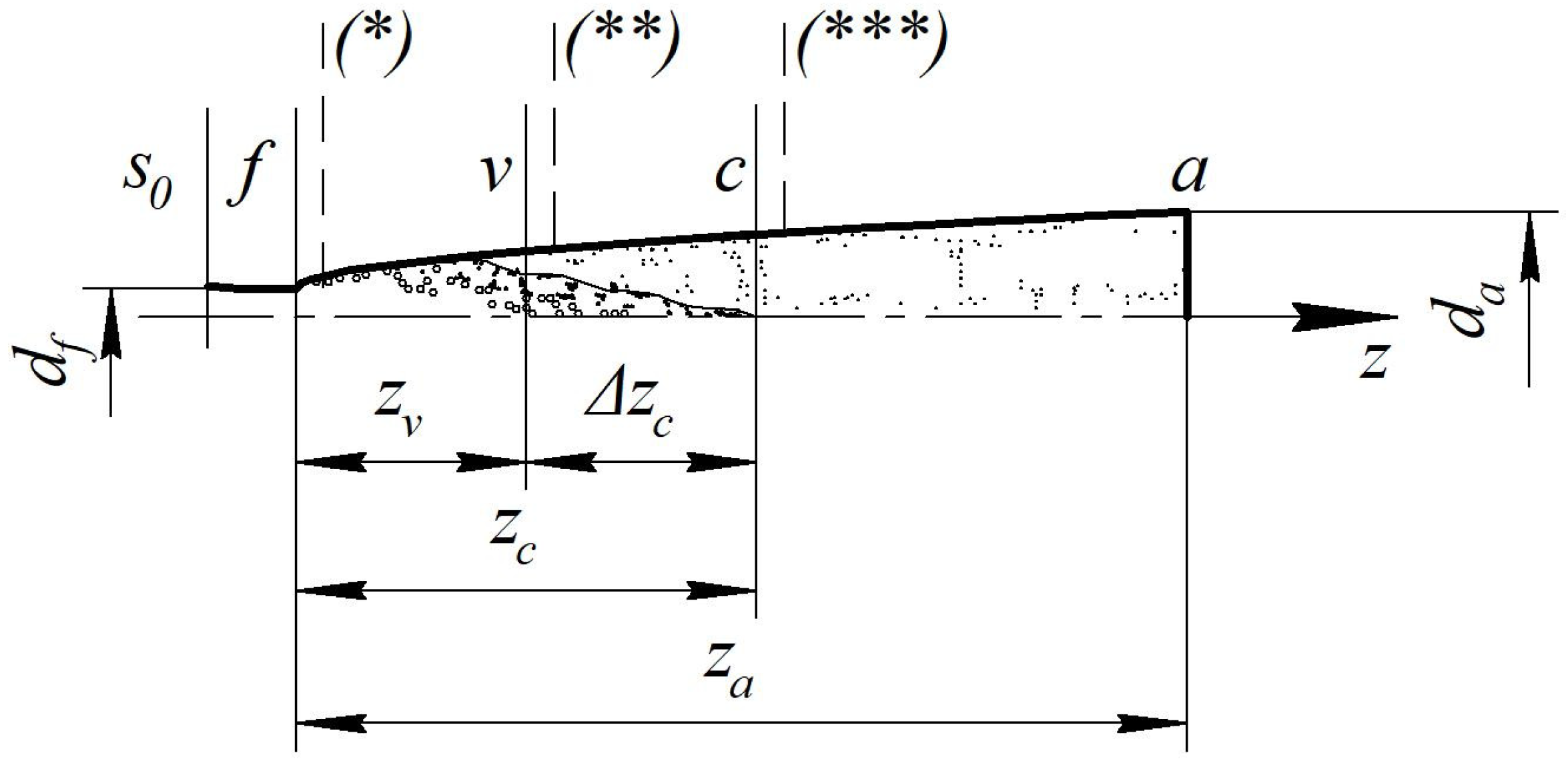
2.1. Design Schemes

This section describes the selection of operating parameters for condition monitoring and the numerical and experimental methods used to study the motive nozzle as a part of an LVJA.
For modeling, 3D models were designed for nozzles that differ in geometric shape and length of the supersonic part, depending on the operation mode (Figure 1).
For a more reliable simulation of vaporization in the subsonic part, the cylindrical section was discarded since there were no changes in the parameters and structural rearrangement of the flow.
At the outlet, a section with dimensions of 100 × 100 × 100 mm was added as the volume of the external environment behind the nozzle for a more reliable evaluation and visualization of the flow coming out.
Then, using ANSYS CFX 2024 R1 software (ANSYS, Inc., Canonsburg, PA, USA), an unstructured calculation grid was built with an average number of 5.5 × 10⁶ cells that depends on the geometric shape of the supersonic part of the nozzle. The grid type is adaptive tetrahedral (Figure 2).
To carry out the simulation, the necessary initial data are considered. The inlet medium is water and the outlet medium is steam. Calculations are made for the operating modes of the LVJA presented in Table 1, which depend on the application scope.
To describe the phase transition processes, the cavitation model of the mass transition was set; the saturation pressure depends on the difference in pressure and temperature [25]. This model is based on the solution of the Rayleigh–Plesset equation, which is derived from the Navier–Stokes equations. It determines the dynamics of the nucleation and development of a spherical bubble in an infinite body of incompressible fluid. To solve it, it is necessary to consider the following assumptions: the liquid is unbounded, its density and kinematic viscosity are unchangeable, and the pressure inside the bubble is uniform. The boundary conditions “free outlet” and “average static pressure” were set at the outlet. Also, to create a model, it is necessary to set the friction ratio on the walls, the inlet and outlet temperatures, and the outlet pressure. To clarify the simulation, the mass flow at the inlet was set.
The specified conditions make it possible to simulate the processes in the nozzle and to obtain changes in pressure, temperature, density, and flow rate along the nozzle. They also allow for visualizing phase transition in the outflow of underheated boiling working fluid for the primary flow.
The Navier–Stokes equations averaged by Reynolds for a compressible fluid [26,27] were solved using ANSYS CFX during numerical simulations.

2.2. A Mathematical Model

The governing equations consider the mass and energy conservation laws in a one-dimensional approximation:
d w F υ l i q t l i q + χ υ v a p t v a p , p = 0 ;
m ˙ d w = F d p τ w П d z ;
d h l i q t l i q + x h v a p t v a p , p h l i q t l i q + w 2 2 = 0 ;
d s l i q t l i q + x s v a p t v a p , p s l i q t l i q > 0 ,
which are solved together with the vaporization equation:
d x = b v a p f υ 0 υ v a p t v a p , p υ l i q t l i q p s t l i q p w f d z ¯
and dependencies for the nozzle shape f = α c , z ¯ , and the shear stress on the wall:
τ w = c f w 2 2 υ ,
where υ—specific volume of a particle of the i-th distribution group, m3/kg; t—temperature of a particle, °C; w—average flow velocity, m/s; F—the cross-sectional area for the channel, m2; h—specific enthalpy of particles, J/kg; τw—shear stress on the channel’s wall, Pa; П—the channel’s perimeter, m; s—specific entropy of particles, J/(kg·K); c f = f Δ , d , M , —dimensionless friction coefficient. Indexes “liq” and “vap” indicate flow parameters in the liquid and vapor modes, respectively.
The equations mentioned above allow for the evaluation of the parameters in each section of the supersonic part of the nozzle, depending on the position relative to the critical sections (Figure 3).
The relative initial underheating at the inlet is determined as follows:
1 ε s 0 = P 0 P s 0 P 0 = 1 P s 0 P 0 ,
where P s 0 —saturation pressure temperature t 0 .
At the section “fv”, the following parameters are determined:
P v = ε v P s 0 ;
w v i = γ v i w f ;
x v i = 1 1 + 1 β v 1 υ v υ 1 v     ,
where P v —pressure, Pa; w v i —velocity, m/s; x v i —mass vapor content, kg/kg; ε v —relative initial underheating in the cross-section “v”; w v i —flow rate in the i-th cross-section of the section “fv”, m/s; w f —flow rate in the flow section, m/s; β v —volumetric vapor content, m3/m3; γ v i —relative outlet velocity in the i-th cross-section of the section “fv”:
γ v i = υ 1 v + x v i υ v υ 0 f v i ,
Here, f v i —the i-th cross-sectional for the nozzle at the section “fv”:
f v i = 1 + c k i z v i ,
where c k i —the radial size of the nozzle in the i-th cross-section at the section “fv”, m; z v i —the distance of the i-th cross-section from the flow section, m.
In the section “vc”, the following parameters are determined:
P c = P v z c i z v z k z v P v P a ;   z k = b a z a ;
w c i = γ c i w f ;
w f = μ 0 υ f 2 P 0 P 01 P s 0 υ 0 ;
γ c i = γ v i + P 0 υ 0 f v i P v f c i P c + ( f c i f v i ) P ¯ v a p w f 2 ;
P ¯ v a p = 1 n j = 1 n ( P ¯ j P w j ) ;
P w j = P 0 ξ 4 c k w f 2 v 0 γ 1 f 1 ;
x c i = f c i υ 0 γ c i υ c ;
M c i = w c i a 2 * ;
a 2 * = k υ 2 P 0 P 2 β 2 ;
v 2 = υ 0 f c γ c .
where P c —pressure, Pa; w c i —velocity, m/s; w f —velocity in the flow section of the nozzle, m/s; P 0 = 1.0 × 10⁵ Pa—atmospheric pressure; γ c i —relative outlet flow rate; P ¯ v a p —average vapor pressure, Pa; P w j —pressure difference, Pa; x c i —mass vapor content, kg/kg; M c i —Mach number; a 2 * —local sound velocity in a two-phase flow, m/s.
At the section “va”, the following parameters are determined:
P a i = P c ± P ,
where the calculation is carried out while the condition becomes fulfilled P a i P a :
w a i = γ a i w a s ;
w a s = 2 κ h 01 h a s 01 s a T a ;
x a i = B + B 2 + C ;
B = κ r 2 f 2 2 w f 2 υ 0 υ a 2 T 1 T a 1 υ 1 υ a ;
C = f 2 υ 0 υ a 2 f a 2 2 κ r 1 x 1 w f 2 T 1 T a 1 υ 1 υ a 2 ;
M a i = w a i a 2 * ,
where κ = 1.0 × 10³—dimension factor;  P a i —pressure, Pa; w a i —velocity, m/s; w a s —velocity of equilibrium isentropic outflow, m/s; x a i —mass vapor content, kg/kg; M a i —Mach number.
Depending on the geometric feature of the supersonic part of the nozzle for the primary flow, the parameter c k i is determined as follows:
(1)
for a conical shape (Figure 1a):
c k i = r d f + z i tg π α 360 ;
(2)
for a parabolic shape (Figure 1b):
c k i = r d f + z i D 2 + 4 z i r d f 2 ;
(3)
for a hyperbolic shape (Figure 1c):
c k i = r d f + R 1 + l a 2 1 1 + L a 2 1 ;
(4)
for an elliptic shape (Figure 1d):
c k i = r d f + R L Z 2 1 z i Z 2 ;
(5)
for a Vitoshynskyi shape (Figure 1e):
c k = R 1 1 R r d f 2 1 l Z 2 2 1 1 3 l Z 2 3 ,
where  R —outlet radius of a nozzle, m; L —nozzle length, m; a —distance to the top of the hyperbola, m; r d f —radius of the inlet cross-section, m.

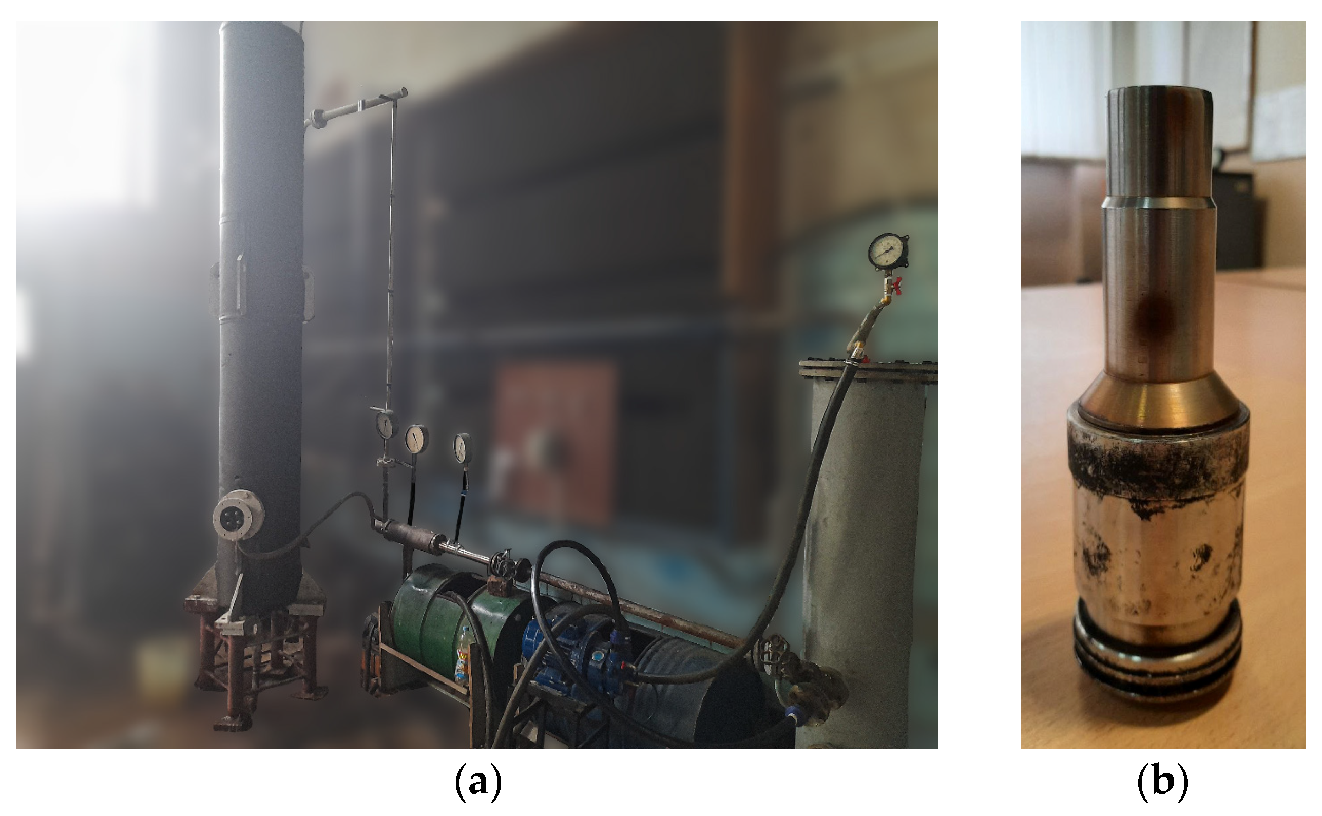
2.3. An Experimental Stand
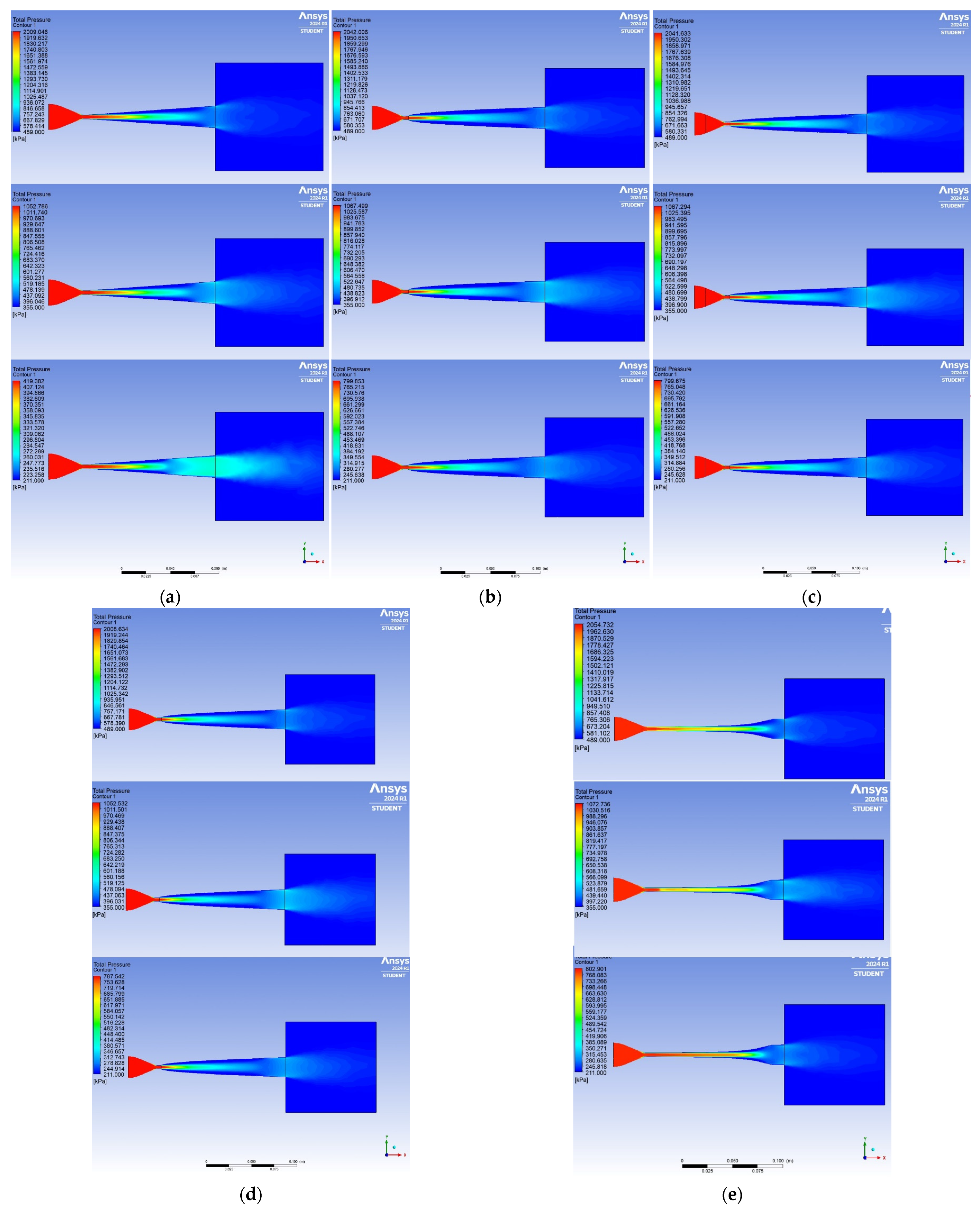
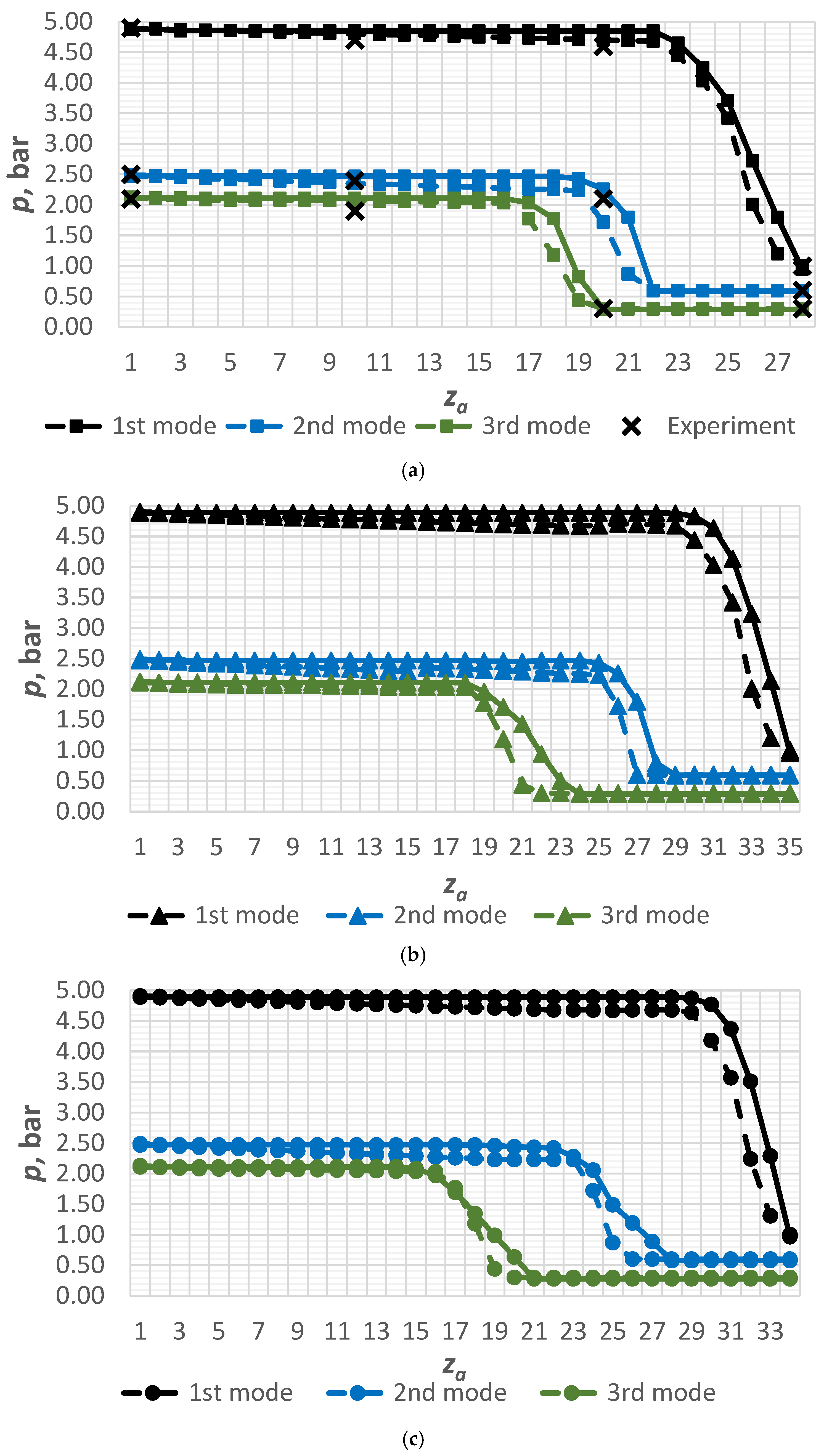
An experimental study of a nozzle with a conical supersonic part (Figure 1a) was carried out on the experimental stand shown in Figure 4.
The design of the experimental sample of the LVJA allows for replacing the supersonic part of the nozzle. This makes conducting experimental studies for all the nozzles in Figure 1 possible.
The ratio of flow metastability, which arises due to the imbalance of the process flow, is expressed as follows:
υ f = m ˙ f m ˙ f = w f w s 0 .
The flow rate ratio determined by the following formula is an indicator of the vaporization efficiency in the nozzle:
φ a = γ a γ a s = w a w a s .
For considering the influence of the actual outflow of the working fluid of the primary flow and the degree of difference in the actual process from the equilibrium isentropic outflow, the following momentum ratio is introduced:
φ i = i a i a s = μ 0 · υ f · φ a .

3. Results

As a result of the calculation study and conducting experimental research, changes in parameters along the nozzle were evaluated according to the operating modes indicated in Table 1.
Figure 5 presents CFD simulation results for changes in pressure along the nozzles of different shapes.
Figure 5 shows that under the same expansion rate, with the transition to the vacuum operation mode (modes 2 and 3, Table 1), the flow separation from the channel walls occurs closer to the flow section. This indicates that less time is needed for the vaporization process in the vacuum mode. Thus, the structural restructuring of the flow occurs faster.
Numerical calculations according to the developed methodology presented in Section 2.2 allow for accurately evaluating the nozzle sections’ position, where the flow’s structural rearrangement occurs. It also allows for determining a rational nozzle length on which the flow will separate from the channel walls (Figure 6).
On the obtained approximation curves, there is a sharp change in the parameters in the outlet section of the nozzle. So, this is where the flow separation occurs. According to the simulation, calculation, and experimental results, it is possible to find the distance to this cross-section, which will be the flow section “aa” with an accuracy of 2–3%. Figure 5 presents CFD simulation results for changes in velocity along the nozzles.
Figure 7 shows that the highest outflow velocities are observed in the first operation mode for conical and elliptical nozzles and reach values up to 550 m/s. These values are lower for nozzles of hyperbolic and parabolic shapes at about 480–500 m/s.
The given velocity values are valid for the first operation mode. This indicates greater completeness of the vaporization process in hyperbolic and parabolic nozzles. This is because they will have a more structured leading edge of the flow for the same length as the diffuser part. Therefore, when mixing with a passive flow in the mixing chamber, it will take less time to equalize the parameters at the exit from the LVJA. In this case, a nozzle with a parabolic shape will be more effective due to the shorter length of the diffuser part (Figure 1).
Figure 8 presents the numerical, calculation, and experimental results for nozzles with different geometry.
The average difference between the calculation and experimental results is up to 5%.
After analyzing the obtained numerical and experimental results, it is possible to determine the vaporization efficiency in nozzles of different geometries by evaluating the velocity ratio. According to research works [17,18], the most effective range of nozzle operation is the interval in which the value of relative initial underheating is 0.2–0.4.
Figure 9 presents generalized theoretical approximations of the velocity ratio on the value of the relative initial underheating.
Figure 9 shows that nozzles with a Vitoshynskyi shape are the least effective since the velocity factor ranges from 0.72–0.95. Moreover, it operates in a narrow range of the relative initial underheating: 1 ε s 0 = 0.25–0.34.
Remarkably, nozzles of parabolic and hyperbolic shapes have the highest velocity ratio (about 0.930–0.987). However, the vaporization process will be the most complete due to the parabolic nozzle’s shorter length and lower velocities. Accordingly, such a nozzle shape will be the most effective. Overall, on average, the efficiency of the profiled nozzles is higher by 6–8%.

4. Discussion

This article describes the developed thermophysical model that can be applied to calculate the vapor formation process in expanding nozzles. This model is more reliable than Prokopov’s model [3] because it is a dynamic model of the boiling flow of a superheated liquid that uses an indirect method for evaluating averaged flow parameters. Its primary advantage is the possibility of assessing an LVJA operating both in compressor and vacuum modes. This is because the model considers peculiarities of the outflow process for the liquid underheated to saturation from channels expanding in the area of pressures both higher and lower than atmospheric. Also, the model is refined to calculate nozzles with different geometry of the diffuser part: nozzles with parabolic, hyperbolic, elliptical, and Vitoshynskyi shapes are considered.
After comparing the results obtained analytically and numerically using ANSYS CFX, one more advantage can be highlighted: the turbulence model calculates the parameters of the liquid and vapor phases separately. As a result, the error between the simulation results and the physical experiment increases. Despite this disadvantage of CFD modeling, the proposed analytical model allows for calculating the thermodynamic parameters of a two-phase mixture, bringing the numerical results closer to those obtained in a physical experiment (Figure 6a and Figure 8a).
The results of analytical modeling and numerical simulations for nozzles with the Vitoshynskyi shape are also quite different. This indicates that such nozzles do not apply to devices where vaporization processes occur. However, as shown by previous studies of the mixing chambers of two-phase jet devices [15,17,18], profiling hybrid conical–cylindrical mixing chambers with the Vitoshynskyi shape formula can be more successful.
The application of the developed thermophysical model is limited by the thermodynamic properties of water and its vapor, which are used in LVJA as the primary flow. The second limitation is the design features of the flow part of the device and, as a result, the pressure ratio for the passive flow.
Since the experimental study was conducted for conical nozzles, further research directions will be to automate the rational selection of the geometric shape for the nozzle’s diffuser part based on the inlet and outlet flow parameters. This requires additional application of the variation calculus and methods for identifying parameters of the developed mathematical model based on more experimental data.

5. Conclusions

As a result of analytical calculations for a liquid–vapor jet apparatus with a profiled supersonic part, the dependencies for the pressure and velocity changes of the boiling flow along the nozzle’s diffuser part were obtained according to the developed analytical thermophysical model.
As a result of numerical simulations for the apparatus with different shapes using ANSYS CFX, the distributions of thermodynamic and mode parameters along the length of the motive nozzle were obtained.
After analyzing the obtained analytical calculation and numerical simulation results, the distributions of thermodynamic parameters in the vapor formation process were obtained for motive nozzles with a profiled supersonic part.
After a comparative analysis of the obtained calculation results with experimental studies in modeling the liquid–vapor jet apparatus with a profiled supersonic part for nozzles with straight walls, the velocity ratios in a range of 0.915–0.987 were evaluated. As a result of comparative analysis, the rational geometric shape of the nozzle’s supersonic part was found to be parabolic, for which the velocity ratio varies in a range of 0.930–0.987.

Author Contributions

Conceptualization, S.S., S.W. and D.H.; methodology, S.S., D.H. and V.K.; software, D.H., I.P. and M.O.; validation, S.W., A.K. and D.G.-K.; formal analysis, V.K., I.P. and M.O.; investigation, S.S., D.H., V.K., I.P., M.O., S.W., A.K. and D.G.-K.; resources, S.S., I.P. and M.O.; data curation, V.K., D.G.-K., S.W. and A.K.; writing—original draft preparation, S.S., D.H. and V.K.; writing—review and editing, I.P. and M.O.; visualization, S.W., A.K. and D.G.-K.; supervision, S.S. and I.P.; project administration, I.P., S.W. and M.O.; funding acquisition, I.P., M.O., S.W., A.K. and D.G.-K. All authors have read and agreed to the published version of the manuscript.

Funding

The Ulam NAWA program partially funded the research, grant number BPN/ULM/2022/1/00042. The research was also partially funded by the Ministry of Science and High Education of Poland.

Data Availability Statement

The data are available by request to the corresponding author.

Acknowledgments

The authors acknowledge the project “Development of a mobile ejector-cleaning unit for the restoration of buildings, structures, and equipment after fires in the war period” ordered by the Ministry of Education and Science of Ukraine (State reg. no. 0124U000636). We also appreciate Maxym Prokopov for the previous support.

Conflicts of Interest

The authors declare no conflicts of interest.

References

  1. Tashtoush, B.M.; Al-Nimr, M.A.; Khasawneh, M.A. A comprehensive review of ejector design, performance, and applications. Appl. Energy 2019, 240, 138–172. [Google Scholar] [CrossRef]
  2. Colarossi, M.; Trask, N.; Schmidt, D.P.; Bergander, M.J. Multidimensional modeling of condensing two-phase ejector flow. Int. J. Refrig. 2012, 35, 290–299. [Google Scholar] [CrossRef]
  3. Prokopov, M. The Thermophysical Design of Working Process of Liquid-Steam Stream Compressor. Ph.D. Thesis, Sumy State University, Sumy, Ukraine, 2012. [Google Scholar]
  4. Lorentzen, G. Revival of carbon dioxide as a refrigerant. Int. J. Refrig. 1994, 17, 292–301. [Google Scholar] [CrossRef]
  5. Liu, J.; Zhou, L.; Cheng, J.; Lin, Z.; Zhang, X. A novel two-stage compression air-source heat pump cycle combining space heating, cooling, and domestic hot water production. Energy Build. 2023, 285, 112863. [Google Scholar] [CrossRef]
  6. Huang, C.; Li, Z.; Ye, Z.; Wang, R. Thermodynamic study of carbon dioxide transcritical refrigeration cycle with dedicated subcooling and cascade recooling. Int. J. Refrig. 2022, 137, 80–90. [Google Scholar] [CrossRef]
  7. Welzl, M.; Heberle, F.; Brüggemann, D. Experimental evaluation of nucleate pool boiling heat transfer correlations for R245fa and R1233zd(E) in ORC applications. Renew. Energy 2020, 147, 2855–2864. [Google Scholar] [CrossRef]
  8. Dai, B.; Liu, S.; Sun, Z.; Ma, Y. Thermodynamic performance analysis of CO2 transcritical refrigeration cycle assisted with mechanical subcooling. Energy Procedia 2017, 105, 2033–2038. [Google Scholar] [CrossRef]
  9. Sharma, D.K.; Pegallapati, A.S.; Ramgopal, M. Performance of a CO2 based transcritical air conditioning system under summer and winter conditions. Therm. Sci. Eng. Prog. 2023, 41, 101847. [Google Scholar] [CrossRef]
  10. Mahmoudian, J.; Mazzelli, F.; Milazzo, A.; Malpress, R.; Buttsworth, D. Experiments on water vapour condensation within supersonic nozzle flow generated by an impulse tunnel. Int. J. Multiph. Flow 2021, 134, 103473. [Google Scholar] [CrossRef]
  11. Sarevski, V.N.; Sarevski, M.N. Characteristics of R718 Thermocompression refrigerating/heat pump systems with two-phase ejectors. In Proceedings of the International Refrigeration and Air Conditioning Conference, West Lafayette, IN, USA, 16–19 July 2012; Available online: https://docs.lib.purdue.edu/iracc/1214/ (accessed on 1 November 2024).
  12. Sutthivirode, K.; Thongtip, T. Performance improvement of ejector refrigerator–based water chiller working with different mixing chamber profiles. Alex. Eng. J. 2021, 60, 3693–3707. [Google Scholar] [CrossRef]
  13. Butrymowicz, D.; Śmierciew, K.; Karwacki, J.; Gagan, J. Experimental investigations of low-temperature driven ejection refrigeration cycle operating with isobutane. Int. J. Refrig. 2014, 39, 196–209. [Google Scholar] [CrossRef]
  14. Butrymowicz, D.; Śmierciew, K.; Karwacki, J.; Borsukiewicz, A.; Gagan, J. Experimental investigations of flow boiling heat transfer under near-critical pressure for selected working fluids. Sustainability 2022, 14, 14029. [Google Scholar] [CrossRef]
  15. Sharapov, S.; Mižáková, J.; Husiev, D.; Panchenko, V.; Ivanov, V.; Pavlenko, I.; Židek, K. Vapor overproduction condition monitoring in a liquid–vapor ejector. Processes 2022, 10, 2383. [Google Scholar] [CrossRef]
  16. Majchrzyk, M.; Dziurowicz, D.; Haida, M.; Palacz, M.; Bodys, J.; Fingas, R.; Smolka, J.; Nowak, A. Detailed numerical investigation of the CO2 two-phase ejector 3-D CFD model based on the flow visualisation experiments. Chem. Eng. Process.-Process Intensif. 2022, 182, 109195. [Google Scholar] [CrossRef]
  17. Chekh, O.; Sharapov, S.; Prokopov, M.; Kozin, V.; Butrymowicz, D. Cavitation in nozzle: The effect of pressure on the vapor content. In Advances in Design, Simulation and Manufacturing II. DSMIE 2019; Ivanov, V., Trojanowska, J., Machado, J., Liaposhchenko, O., Zajac, J., Pavlenko, I., Edl, M., Perakovic, D., Eds.; Lecture Notes in Mechanical Engineering; Springer: Cham, Switzerland, 2020; pp. 522–530. [Google Scholar] [CrossRef]
  18. Sharapov, S.O.; Krmela, J.; Husiev, D.M.; Verbytskiy, A.R.; Bocko, J. Heat utilization in boiler plants by using liquid-vapor jet apparatus. J. Eng. Sci. 2024, 11, G1–G8. [Google Scholar] [CrossRef]
  19. Łapka, P.; Seredyński, M.; Grzebielec, A.; Szelągowski, A. Numerical investigation of nozzle shape effect on the flash boiling phenomenon. In Numerical Heat Transfer, Part A: Applications; Taylor & Francis: Abingdon, UK, 2023; pp. 1–23. [Google Scholar] [CrossRef]
  20. Le, A.D. Study of thermodynamic effect on the mechanism of flashing flow under pressurized hot water by a homogeneous model. J. Fluids Eng. 2022, 144, 011206. [Google Scholar] [CrossRef]
  21. Kumar, A.; Tammone, C.; Haglind, F. Numerical investigation of flashing flow in a convergent-divergent nozzle. In Turbo Expo: Power for Land, Sea, and Air; American Society of Mechanical Engineers: New York, NY, USA, 2023; Volume 6, p. V006T09A009. [Google Scholar] [CrossRef]
  22. Liu, Z.; Wang, S.; Lin, Z.; Wang, X.; Wang, D.; Ouyang, Y.; Zhang, D. A non-equilibrium phase change model based on the Lee model for flashing flows in converging–diverging nozzles. Nucl. Eng. Des. 2024, 423, 113185. [Google Scholar] [CrossRef]
  23. Quang, D.L.; Mereu, R.; Besagni, G.; Dossena, V.; Inzoli, F. Computational fluid dynamics modeling of flashing flow in convergent-divergent nozzle. J. Fluids Eng. 2018, 140, 101102. [Google Scholar] [CrossRef]
  24. Le, A.D.; Thang, H.P.; The, H.T. Assessment of a homogeneous model for simulating a cavitating flow in water under a wide range of temperatures. J. Fluids Eng. 2021, 143, 101204. [Google Scholar] [CrossRef]
  25. Hung, K.-S.; Hsiao, W.-C.; Li, Y.-C.; Kuan, Y.-D. 150USRT class R-513A refrigerant two-stage centrifugal compressor design point and separation point flow field simulation analysis. Processes 2023, 11, 253. [Google Scholar] [CrossRef]
  26. Ayad, F.; Bouaichaoui, Y.; Aboshighiba, H. Fluid-to-fluid similarity and CFD predictions of surrogate fluid as a replacement for R11 refrigerant used in a subcooled flow boiling analysis: Validation against reference experimental data. Int. J. Heat Mass Transf. 2024, 230, 125772. [Google Scholar] [CrossRef]
  27. Praveen, R.; Kumaran, P.; Anandu, S.; Gnana Gokulprasath, S.; Karthickraja, N. Aerodynamic and flow optimization in turbo charger nozzle using ANSYS CFX. AIP Conf. Proc. 2023, 2523, 020006. [Google Scholar] [CrossRef]
Figure 1. Geometric features of motive nozzles with different geometries of the supersonic part: (a) conical shape; (b) parabolic shape; (c) hyperbolic shape; (d) elliptical shape; (e) Vitoshynskyi shape.
Energies 17 06465 g001
Figure 2. Calculation grid for a nozzle with a parabolic shape of the supersonic part (Figure 1b).
Energies 17 06465 g002
Figure 3. The design scheme of the vaporization process in a motive nozzle: “fa”—the supersonic part of the nozzle: f, v, and c—the 1st, 2nd, and 3rd critical sections, respectively; *, **, and ***—real positions of the 1st, 2nd, and 3rd critical sections, respectively.
Energies 17 06465 g003
Figure 4. Experimental stand: (a)—general view; (b)—the conical supersonic part of the motive nozzle.
Energies 17 06465 g004
Figure 5. Pressure changes along the conical (a), parabolic (b), hyperbolic (c), elliptic (d), and Vitoshynskyi (e) shapes of the nozzle according to the mode parameters presented in Table 1.
Energies 17 06465 g005
Figure 6. The numerical and experimental results for pressure changes along the conical (a) (■), parabolic (b) (▲), hyperbolic (c) (●), elliptic (d) (◆), and Vitoshynskyi (e) (○) shapes according to the mode parameters presented in Table 1 (“- - -”—CFD simulation results, “---”—calculation results according to the proposed methodology, “✕✕✕”—experimental results for a nozzle with the conical shape).
Energies 17 06465 g006aEnergies 17 06465 g006b
Figure 7. Velocity changes along the conical (a), parabolic (b), hyperbolic (c), elliptic (d), and Vitoshynskyi (e) shapes of the nozzle according to the mode parameters presented in Table 1.
Energies 17 06465 g007
Figure 8. The numerical and experimental results for velocity changes along the conical (a) (■), parabolic (b) (▲), hyperbolic (c) (●), elliptic (d) (◆), and Vitoshynskyi (e) (○) shapes according to the mode parameters presented in Table 1 (“- - -”—CFD simulation results, “---”—calculation results according to the proposed methodology, “✕✕✕”—experimental results for a nozzle with the conical shape).
Energies 17 06465 g008aEnergies 17 06465 g008b
Figure 9. Evaluated efficiency for nozzles with a diffuser part of conical (■; blue line), parabolic (▲; red line), hyperbolic (●; yellow line), elliptic (◆; black line), and Vitoshynskyi (○; green line) shapes vs. relative initial underheating.
Energies 17 06465 g009
Table 1. Geometrical and mode parameters of nozzles.
Modepin, bartin, °Cpout, barm, kg/s
1202001.000.83
2101500.500.44
361100.290.24
pin, pout—inlet and outlet pressure, respectively; tin—inlet temperature; m—mass flow rate.
Disclaimer/Publisher’s Note: The statements, opinions and data contained in all publications are solely those of the individual author(s) and contributor(s) and not of MDPI and/or the editor(s). MDPI and/or the editor(s) disclaim responsibility for any injury to people or property resulting from any ideas, methods, instructions or products referred to in the content.

