Article

Implementation of Regenerative Thermal Oxidation Device Based on High-Heating Device for Low-Emission Combustion

by
Hoon-Min Park
1,2,
Dal-Hwan Yoon
3,*,
Joon-Seong Lee
1,
Hyun-Min Jung
1,2,
Dae-Hee Lee
1,2,
Dong-Hwan Jeon
4 and
Tae-Yeung Lim
2
1
Department of Mechanical Engineering, Kyonggi University, Suwon 16227, Republic of Korea
2
Emsolution Co., Ltd., Suwon 16227, Republic of Korea
3
Department of Electronic Engineering, Semyung University, Jecheon 27136, Republic of Korea
4
Institute of Advanced Engineering, Yongin 17180, Republic of Korea
*
Author to whom correspondence should be addressed.
Energies 2024, 17(20), 5182; https://doi.org/10.3390/en17205182
Submission received: 31 August 2024 / Revised: 11 October 2024 / Accepted: 11 October 2024 / Published: 17 October 2024

Abstract

:
In this paper, a heating device is implemented by considering two large factors in a 100 cmm RTO design. First, when the combustion chamber is used for a long time with a high temperature of 750–1100 °C depending on the high concentration VOC gas capacity, there is a problem that the combustion chamber explodes or the function of the rotary is stopped due to the fatigue and load of the device. To prevent this, the 100 cmm RTO design with a changed rotary position is improved. Second, an RTO design with a high-heating element is implemented to combust VOC gas discharged from the duct at a stable temperature. Through this, low-emission combustion emissions and energy consumption are reduced. By implementing a high heat generation device, the heat storage combustion oxidation function is improved through the preservation of renewable heat. Over 177 h of demonstration time, we improved the function of 100 cm by discharging 99% of VOC’s removal efficiency, 95.78% of waste heat recovery rate, 21.95% of fuel consumption, and 3.9 ppm of nitrogen oxide concentration.

1. Introduction

Globally, efforts are being made to reduce greenhouse gases and zero carbon due to global warming. The increase in global average temperature in response to climate change is maintained within 2 °C compared to pre-industrial times, and in the long run, it is achieving 1.5 °C [1].
Volatile organic compounds (VOCs) emitted from chemical plants, metal painting plants, and petroleum plants must be urgently addressed due to air pollution as well as toxicity and carcinogenicity to humans [2,3]. In order to remove volatile organic compounds, oxyfuel combustion technology using the oxyfuel combustion properties of pulverized coal has been proposed [4]. The use of gas in constant combustion for gas turbine combustion and ammonia removal has increased CO2 emissions [5]. Worldwide, combustion facilities of liquid and gaseous fuels often operate continuously for long periods of time. Most facilities are old and operate and low efficiency, producing significant amounts of pollutants, which negatively affects the environment.
On the other hand, a solution for increasing fuel conversion efficiency by recovering heat in a process of repeated cooling and steam condensation in a combustion process has been proposed [6]. This solution is evaluated as an algorithm to improve the economic feasibility of a heat source by significantly reducing fuel consumption. A study was also conducted to reduce the emission of nitrogen oxides (NOs) generated in the furnace during the iron smelting process [7]. However, in the empirical process using a single burner combustion system, the ratio before and after combustion did not decrease.
As an approach to using waste as energy, an eco-friendly way of injecting and discharging superheated steam into combustion zones has also been proposed [8]. However, methods using recycling increase carbon dioxide, and there is research into how to capture it. Based on the air injection function of RTO [9], a screening method was studied to evaluate the oil recovery (EOR) storage stability. Through this study, various characteristics such as peak temperature change, oxygen absorption, CO2 production, oxidation and combustion operation, total combustion carbonized water, and residual combustion were analyzed. In order to apply the RTO experiment to field combustion (ISC) modeling, verification and computational data matching based on numerical simulations of the RTO test must be performed using the 3D digital model of the experimental setup. Therefore, the purpose of this study is to estimate dynamic parameters for customized response models that accurately represent ISC.
Until now, VOC removal and reduction technologies have been studied as anti-diffusion methods, physical methods, chemical methods, biological methods, etc. [10]. Among the chemical methods, combustion oxidized and decomposed VOCs at high temperatures and developed into direct combustion methods (thermal oxidizing agents), catalytic oxidizing agents, and regenerative thermal oxidizing agents. Among them, energy costs are consumed with a low heat recovery rate of 95% or more, and technologies capable of effectively treating VOC throughput by 95% or more include heat storage combustion systems and heat storage catalyst combustion systems. The porous plate scrubber [11], which is a dust-collecting cleaning device, has been developed into an aqueous type, a rotary type, and a pressure type.
Meanwhile, the type of heat storage combustion oxidizing agent for the treatment of volatile organic compounds was developed from the first- and second-generation damper methods to the third-generation rotary valve method [12]. This rotary valve method has a high VOC removal efficiency of 95%, but as a large installation area is required, the development of process automation and optimization algorithms is actively underway, and research on process design and improvement is also underway. To reduce air pollution at VOC production sites, we designed 100 CMM regenerative thermal oxidation (RTO) units and proposed heat transfer system specification design and emission concentration measurement technology for high-temperature waste heat recovery [13].
Recently, strategies to reflect carbon reduction in corporate environmental, social, and governance (ESG) sustainability are spreading around the world, and as interest from all members of society such as consumers, investors, and government increases, it is emerging as a key element of corporate survival [14]. In particular, efforts to reduce carbon through LCA (Life Cycle Assignment) evaluation from materials to waste have reached the level of concern for climate air problems and corporate survival.
In this paper, the structural design considering the load of the combustion chamber is improved to reduce the fatigue of the RTo, and a high-heating element-based 100 mm regenerative heat oxidizer (RTO) is implemented for stable combustion function in the combustion chamber. Existing RTOs have limitations in maintaining continuous temperature by thermally expanding to a high temperature of 800 °C or higher, and in the worst case, there is a problem that rotation stops or explodes. To overcome this, we developed an RTO device that is mixed with a burner and a high-heating device, and over 177 h of experiments, we obtained results of more than 95% for VOC gas removal rate, an oxidation efficiency of 97.87%, a 95.78% waste heat recovery rate, a 21.95% energy reduction, and a nitrogen oxide concentration of 3.9 ppm.

2. Improved 100 CMM RTO Implementation with High-Heating Device

2.1. RTO Modeling and Operating Characteristics

In general, the RTO system is operated in the form of a cylindrical drum equipped with rotating disks and burners through the process of introducing, burning, and discharging VOC gas. The prolonged use of the disk-drum-type rotating body often results in fine pollutants and the rotation of the disk drum is often stopped due to thermal expansion caused by the high temperature of 800 °C. In this case, the pollutant is not effectively purified and damage to the distributor can result in gas leaks, fires, or explosions. Since the RTO device operates according to the operational PLC (programmable logic control) device setting, it must be stopped or repaired according to trip conditions [13]. Figure 1 shows accident site cases such as the resin reprocessing process, an RTO explosion installed in a petrochemical plant, and a stop due to abnormal behavior.
In order to solve this problem, it is necessary to design compactly the rotating part and the air-blocking part, which secures a structure and design technology capable of controlling the gas flow while having excellent durability. Table 1 shows the 100 cmm RTO design specifications.
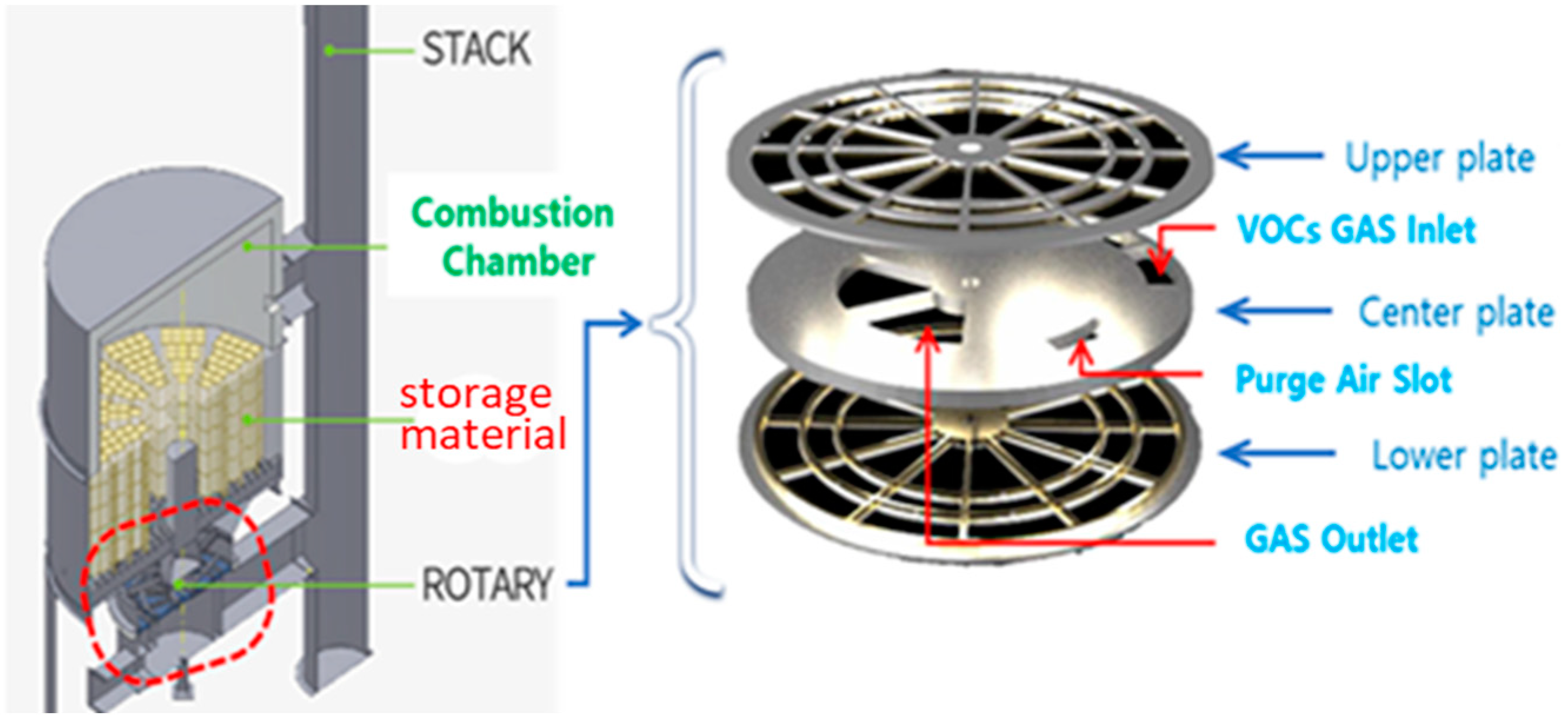
Figure 2 shows the 3D design structure of the 100 cmm RTO system based on Table 1. In Table 1, the combustion chamber is a structure for maintaining a sealed state of waste gas, a 250 mm thick ceramic block insulation is installed inside, and each ceramic material for heat exchange consists of a flange connection structure [8]. The operating temperature of the combustion chamber is designed to operate at 800–850 °C in the burner, but it can operate up to 1100 °C. The temperature maintenance specifications of the combustion chamber vary from country to country, and in certain countries, we hope to maintain it at 910 °C. The effect of removing more than 95% of VOC through the combustion action of the burner in the chamber, the connection of the ceramic heat storage material, and the effect of reducing harmful gas passing through the ceramic side heating material can affect the economic evaluation of the RTO.
The heat storage material is divided into 12 parts under the ceramic heat storage material, and a chamber grid is positioned to support the heat storage material. The purge pipe serves to separate the flow of air introduced from the outside and discharged by the purge fan, and the air supplied to the purge pipe is supplied into the chamber to prevent the mixing of gases introduced into the inlet pipe and the outlet pipe, respectively. The VOC air distribution plate is divided into an upper plate, an intermediate plate, and a lower plate, and is installed in the lower part of each chamber to distribute the inlet air and the outlet air. Each plate is disposed on the path of the inlet pipe, the purge pipe and the outlet pipe to separate or control the flow of air. The intermediate plate is in the form of a flat disk, and an inlet, a purge, and an outlet are sequentially composed from the center [12].
Figure 3 calculates the energy index flow according to the 100 cmm RTO design process in Figure 2. The algorithm is calculated according to the processing gas flow rate and VOC concentration.
In Figure 3, the VOC gas input to the central RTO device is input through the main fan and purge fan, where the energy index of the burner for combustion and the output energy index algorithm discharged after combustion are calculated.

2.2. Energy-Saving 100 cmm RTO Design with a High-Heating Element

A.
Improved RTO air distributor design
Figure 4 is an improved 100 cmm RTO based on the energy index in Figure 3. In Figure 4, the initial design form is the existing RTO structure where the combustion chamber and the lower rotary are connected in series. Depending on the operation of the combustion chamber, rotary devices operating for a long time can malfunction due to irregular movements and loads over time, resulting in accumulated fatigue. This can directly lead to system shutdown or explosion, which can lead to economic loss. In the second figure, to avoid this problem, the central axis of the rotary distributor was designed to the side to reduce the load burden due to vibration or high pressure and improve fatigue. The last figure shows the system implementation in accordance with the actual design, with the red line moving to the right side to indicate the designed rotary distributor.
Figure 5 shows the 3D configuration of the rotary distributor in Figure 4. The rotary distributor was designed based on Figure 3, and the main input is the part connected to the plant duct, which is designed and implemented by following the VOC gas flow rate, temperature, energy reduction efficiency, and reflecting the purge input air condition.
B.
Improved combustion chamber design with a high-heating element
In the existing RTO chamber, the VOC gas combustion method using only a burner is mainly used. When the temperature of the combustion chamber drops below 800 degrees Celsius, uniform combustion efficiency can be obtained by increasing the temperature using LPG. At this time, the CO2 is generated and efforts are being made to remove it [11,12]. On the other hand, research is underway to improve the combustion function and increase the efficiency of removing harmful gases while continuously maintaining the temperature of the combustion chamber between 800 and 850 degrees. To this end, we design a 100 cmm RTO applying a high-heating element that can increase the overall energy efficiency and the efficiency of removing harmful gases.
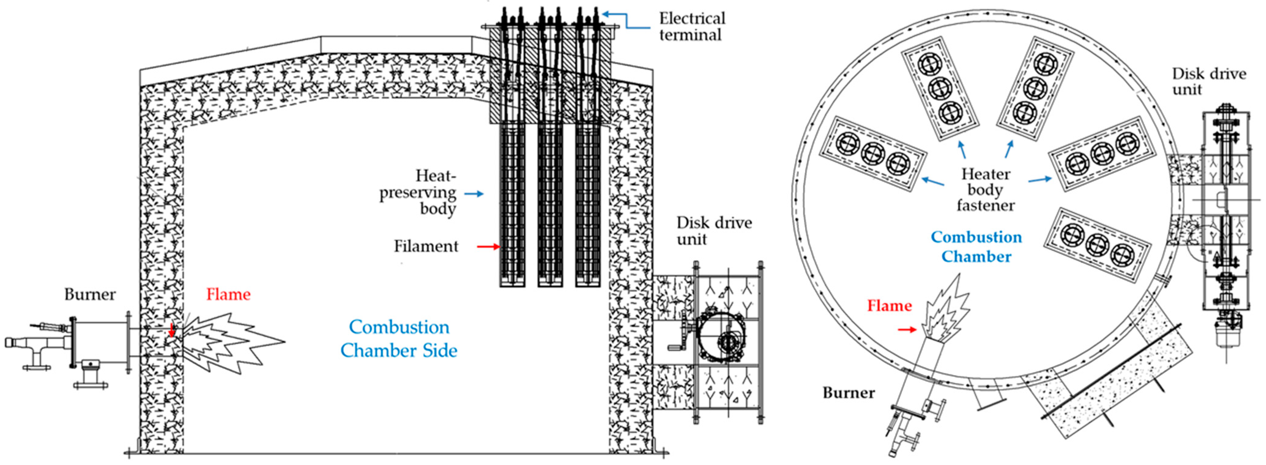
Figure 6 shows the design of the combustion chamber with high-heating elements. The gas burner is designed with a diameter of 125 mm and an outlet of 650 mm × 650 mm, taking into account that it rises to 920 °C to release high-temperature waste heat. At this time, the combustion chamber heat storage material is calculated as a ceramic block with a thickness of 250 mm. In consideration of the residence time of the processing gas and the thickness of the insulation, the combustion chamber is designed with an outer diameter of 2530 mm and a height of 1875 mm. The driving force of the disk rotating plate can release the untreated gas by applying tension around the rotating shaft. At this time, efficiency improvement can be confirmed by improving the rotating plate driving unit to reduce energy consumption.
The high-heating element is designed to configure three heating elements into one module for convenience of construction and smooth maintenance, and in the case of the heater material, since the leakage current is severe at 800 °C or higher, an RT heater that can be used at a high temperature of 1300 °C was designed. In fact, the high-temperature combustion chamber has a risk of explosion due to pressure. The operating function that operates up to 1000 °C in consideration of safety is reflected in the programmable logic controller (PLC). At this time, the PLC setting test is performed according to various trip conditions, and if the rated capacity is out of the range, then the device is stopped or a warning message is displayed. Table 2 shows the design specifications of the high-heating device.
The design specifications of the high-heating element in Table 2 design the capacity of the high-heating element according to the waste heat recovery rate condition of 95% or more based on the processing gas flow rate of 100 cmm RTO, which applies the heat supply standard through the high-heating element and the operation rate standard of 50% or more to promote stable operation. As a result of calculating the design capacity, a high-heating element with a capacity of 117 kW/h is calculated to be suitable.
C.
Design of the ceramic heat storage
Figure 7 shows the design of the ceramic heat storage material inside the combustion chamber to which the high-heating element is applied. The operation of oxidizing VOCs in the combustion chamber to which the high-heating element is applied is evenly displayed throughout the combustion chamber. Therefore, the effect of reducing VOC gas can be improved through the combination of the burner and the high-heating element, and the overall energy-saving effect can also be expected by removing the LPG gas consumption required for long-term system operation.
The method of obtaining the ceramic heat storage agent arrangement algorithm required for recovery of waste heat in the combustion chamber was set to an RTO treatment flow rate of 100 cm, a combustion chamber operating temperature of 800 °C, a processing gas of 25 °C, and an air distribution revolution every 3 min. At this time, based on the calculation of the amount of heat to be stored, the air flow rate is 100 m3/min, the temperature increase is 25 °C to 800 °C, the specific heat of the air is 1005 J/kg⋅K (assuming an ideal gas), and the air density (25 °C, 1 atm) Q is 1.184 kg/m3. The calorific value Qceramic is as follows at ΔT, which is the difference between the mass m of air heated per minute and the temperature:
m = flow rate × density (Q)
Qceramic = mass × heat capacity × ΔT
Here, as a result of the calculation, m is 100 m3/min × 1.184 kg/m3, and Qceramic is 92,218,800 J/min. The amount of heat stored in ceramic Qceramic and the heat storage agent quantity N is calculated as follows:
N = R e q u i r e d h e a t   ( Q ) H e a t s t o r a g e a m o u n t   ( Q c e r a m i c )
Here, the energy of the Qceramic is 3,138,750 J. Thirty heat storage agents are required for 810 J/kg⋅K (applied table values), 1 mass of heat storage agent, and 5 kg of heat recovery. Temperature differences are applied at 100 °C.
Qceramic and N are estimates, and it is assumed that the characteristics of the air and the heat storage device are constant over the temperature range. Differences occur in the waste heat recovery characteristics under the actual temperature distribution conditions, and more accurate results can be secured by considering the temperature change between the heat storage bodies. Through this heat storage material arrangement design, the device diameter was reduced from 2610 mm φ to 2480 mm φ, and the design technology was improved by reducing a total of 60 ceramic fillers (5/zone × 12 zone → 60) compared to the existing method.

3. Experimental Results

The main contents of the 100 cmm RTO implementation are divided into three parts: rotary distributor design, burner and high-heating element mixture design, and ceramic heat storage material design. To illustrate the theoretical properties, we analyze the heat flow characteristics of the heat and analyze the fuel consumption reduction efficiency, VOC reduction efficiency, and THC measurements through field experiments. Here, the VOC concentration measurement is performed using the total hydrocarbon (THC) analysis method, which is an air pollution process test method. In particular, the VOC reduction rate is calculated by simultaneously measuring the VOC gas inlet and outlet in the RTO.

3.1. Simulation of RTO Combustion Chamber

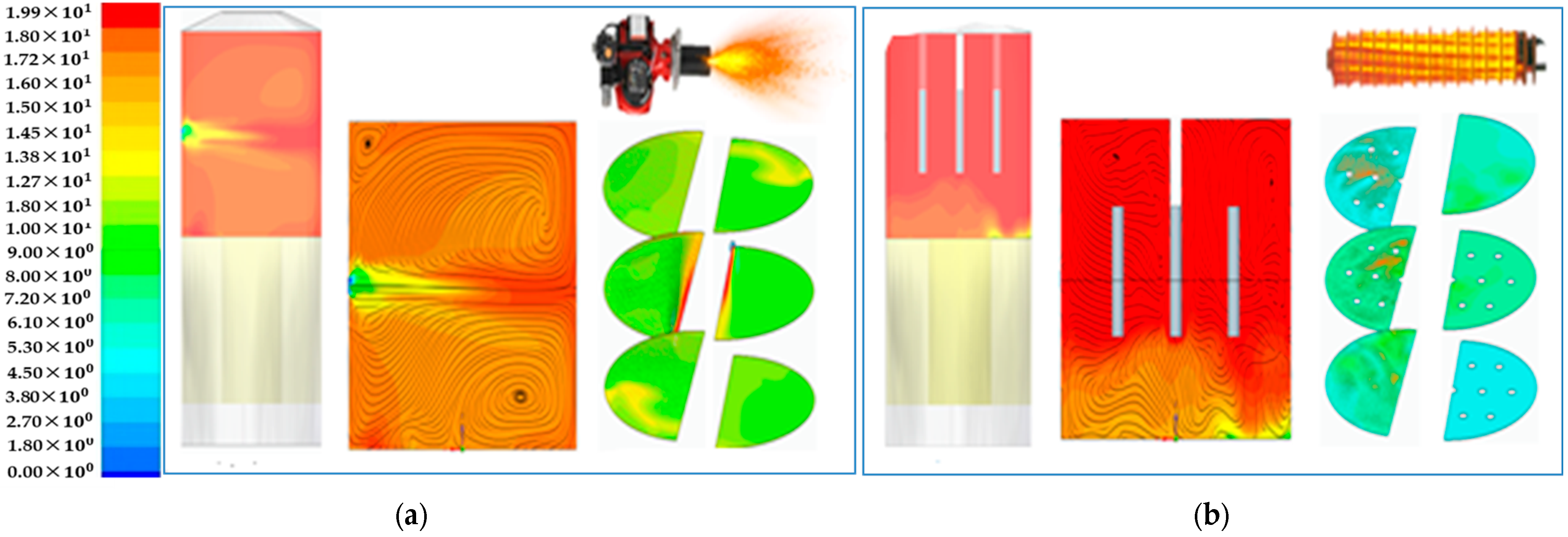
Figure 8 simulates the combustion characteristics according to the temperature characteristics and air flow of the burner and high-heating element at 800 °C. Figure 8a shows the temperature distribution and air flow characteristics of the combustion chamber where only the burner is applied, a curved jet stream is formed according to the burner flame, and gas combustion characteristics according to the temperature distribution are analyzed. At this time, the green color in the center of the jet stream indicates the incomplete combustion of the VOC gas. In Figure 8b, the flowability phenomenon of the jet stream is as shown in Figure 8a, and it can be seen that the combustion process of the VOC gas in the combustion chamber proceeds evenly. The rod shape in the center of the figure is a structure in which three high-heating elements are arranged. Gas flows in from the lower left and gas is discharged to the lower right. At this time, a slight unburned characteristic appears green at the bottom, but this can be seen as a phenomenon corresponding to the emission part of the VOC gas in the combustion chamber.
When the temperature of the combustion chamber falls below 800 °C and the combustion function decreases, a lot of energy is required and economic loss occurs in order to maintain the continuous temperature. Therefore, when operating a combustion chamber that combines a burner and a high-heating element, it may be expected that VOC gas emission may be minimized by improving the combustion function.

3.2. Flowability Analysis of Rotary Distributor

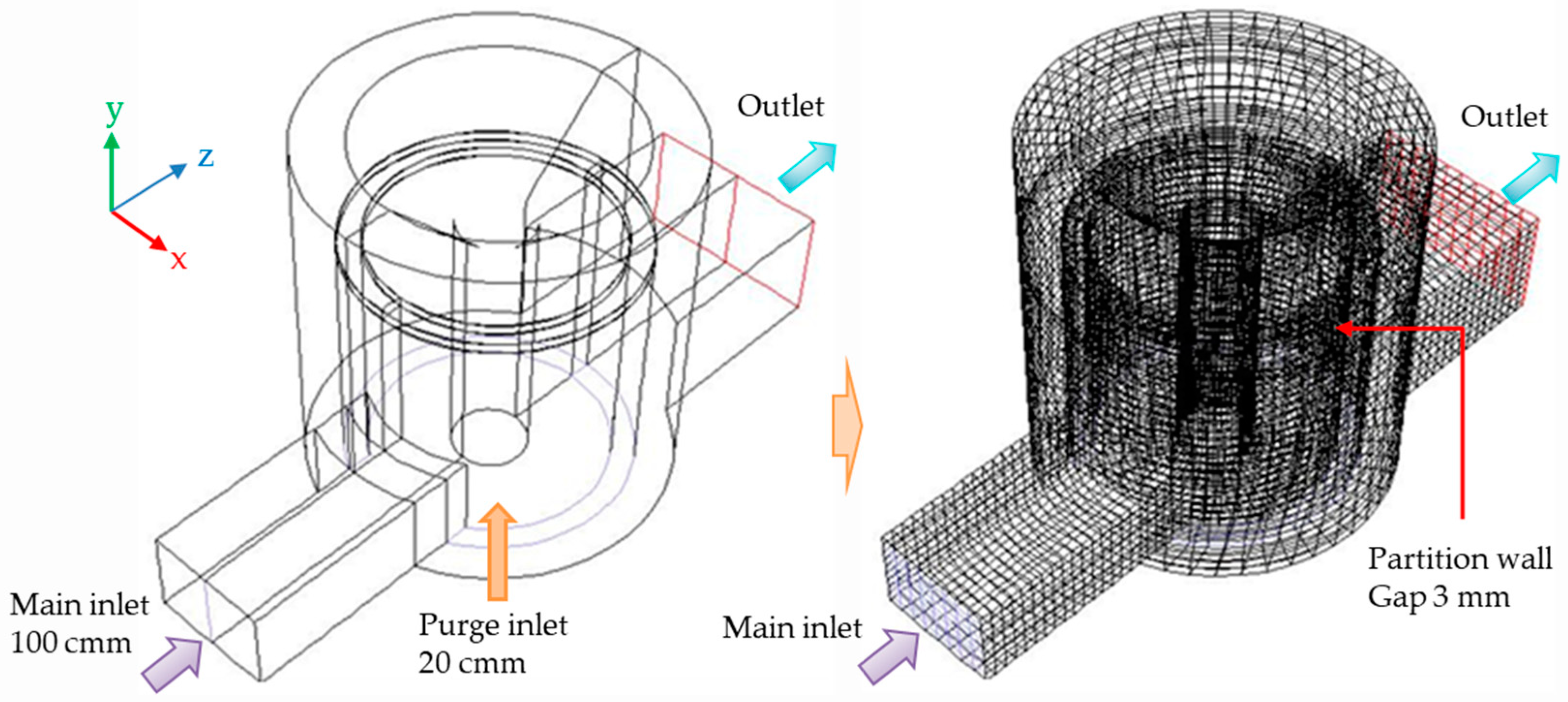
Based on Figure 6 and Figure 7, a 100 cmm RTO combustion chamber is designed and composed of the rotary distributor in Figure 5 under the combustion chamber. Figure 9 simulates gas flow according to gas input and discharge information in this rotary distributor. In the figure, the wired curve represents the air flow, increasing toward the top of the red and decreasing toward the bottom of the blue with intensity. At this time, the size according to the pressure, air speed, and VOC gas concentration is expressed in colors.
In Figure 10, the VOC gas flowing into the RTO device for testing approaches the combustion temperature as it passes through the preheated ceramic heat storage material layer. The VOC gas passing through this layer is burned in the combustion chamber to generate heat at the same time and is oxidized and decomposed at 700 to 800 °C by the amount of heat generated. As shown in Figure 9, the exhaust gas discharged to the rotary outlet stores high-temperature waste heat in the ceramic while passing through the heat storage material on the outlet side, and heat storage and heat dissipation intersect at regular intervals according to the cycle. At this time, the VOC removal efficiency is 95% or more, the energy efficiency is 98%, and it is oxidized and decomposed into a harmless and odorless clean gas of 60 °C and discharged. Table 3 shows the simulation results of the rotary inlet and outlet in 98% or more of heat recovery efficiency and energy treatment efficiency. When simulating the concentration according to various pressures and speeds, a slight leakage occurred at a constant pressure and speed standard. This is a problem of the configuration process and is solved through design correction.

3.3. Experimental Results of 100 cmm System

The final designed and manufactured RTO device experiment tests the performance of removing the concentration of VOCs discharged from the VOC gas outlet generated in the coating film production system. For the validity of the experiment, it was conducted with the Korea Testing Laboratory (KTL) [15]. Figure 10 shows the process of establishing an RTO experiment pilot based on high-heating elements and consists of a chamber body, burner, a heat storage agent filling part, a rotary air distribution part (main fan, purge fan), PLC configuration, and RTO monitoring.
Figure 11 shows the concentration of VOC gas emitted from (a) the drying part and (b) the printing part of the coating film production system. The concentration of the drying part changed between a maximum of 3979 ppm and a minimum of 593 ppm, and the average THC was 2567 ppm. The concentration generated by the printing part changed between a maximum of 2170 ppm and a minimum of 686 ppm, and the average THC was 1260 ppm. The concentration of VOCs discharged during production was irregular, and it was confirmed that the concentration of VOCs discharged during facility inspection such as printing replacement and ink replacement decreased to 200 ppm.
In the air pollution process test method, the facility inlet gas and exhaust gas concentration are simultaneously measured using a total hydrocarbon (THC) analysis method to calculate the VOC reduction rate as shown in the following Equation (4).
V O C   r e d u c t i o n   r a t e % = 1 o u t p u t   T H C   c o n c e n t r a t i o n i n p u t   T H C   c o n c e n t r a t i o n × 100  
Table 4 shows the average value of total hydrocarbons measured at the front and rear ends by injecting nitrogen oxide at a standard oxygen concentration for 30 min, and at this time, the VOC reduction rate is measured.
Table 5 shows the amount of fuel reduction when the RTO device reaches the normal standard by comparing the existing amount of fuel used (3.487 m 3 · L P G / h = 56.413 kWh) with a high-heating element (the amount of power applied to the heating element filament and the amount of fuel used = 44.032 kWh). The fuel reduction rate is calculated in Equation (5).
F u e l   r e d u c t i o n   e f f i c i e n c y   ( % ) = T r a d i t i o n a l   R T O   w i t h   o n l y   f u e l I m p r o v e d   R T O   f u e l   u s a g e T r a d i t i o n a l   R T O   w i t h   o n l y   f u e l × 100
Figure 12 shows the temperature characteristics according to the combustion chamber operation of the RTO to which the burner is applied. After reaching 800 °C, the combustion chamber operating temperature was cooled to 750 °C by operating the on-site exhaust gas transfer blower at 50 Hz, and then the temperature was raised again. After that, when the burner is operated, the combustion chamber temperature deviation is 799–804 °C, showing a deviation of about 5 °C.
Economic VOCs can be removed only when the temperature of the combustion chamber is maintained at 800~850 °C, and some countries require 910 °C to increase the efficiency of the combustion chamber. The stability of a certain temperature according to the operating hours in Figure 12 must be maintained. Therefore, the VOC gas emitted from the factory is irregular every season or quarter, and when the temperature drops below 750 °C, the RTO using only the burner uses LPG to increase the temperature, which increases energy consumption. To identify this, temperature drops and stability experiments below should be considered during the test process.
Figure 13 shows the temperature operation results of the combustion chamber in which a burner and a high-heating element are combined at the same time. In the combustion chamber, the temperature deviation is 10 °C in some sections, and the temperature deviation is 3 °C in the overall stable temperature maintenance section. Compared to the left figure using only the burner, the temperature characteristics are maintained. At this time, the ratio of power supplied to the high-heating element under normal operating conditions was about 20 to 35%, but rather, energy saving was achieved by intermittently supplying power to maintain a stable temperature.
Comparing Figure 12 and Figure 13, it can be seen that the temperature characteristics of the combustion chamber using high-heating elements are evenly displayed, resulting in an improvement in the VOC reduction rate and fuel-saving efficiency. Even temperature characteristics mean that fuel consumption can be reduced, a stable combustion chamber can be maintained, and the meaning of the burner and high-heating element fusion can be strengthened. Table 6 shows the RTO test results according to the design conditions of Table 2.
At this time, the combustion energy was 117,578 kcal/hr, hot bypass leak was 11,758 kcal/hr, and the fuel consumption was 80,450 kcal/hr, which generated surplus heat. The passing temperature of the heat storage material was 735 °C, which was a relatively stable temperature, and the recovery heat was 1,911,341 kcal/hr. The pressure loss occurred from 250 to 253 mmAq due to the expansion and reduction in the heat storage material, stack, and rotary, as well as other expansions. Therefore, if the VOC reduction rate of the RTO system is calculated according to Equation (1), the VOC removal rate of the burner-type RTO system was 95%, but the RTO system based on the high-heating element was 97.87%.

4. Conclusions

A 100 cmm regenerative thermal oxidation device with a high-heating element was implemented for low-emission combustion at VOC-generating workplaces. The thermal energy accumulated in the heat storage material and the improved RTO distributor were redesigned to achieve the safety of disk operation in the combustion chamber. Through this, the gap between the upper and lower plates in the lower part of the combustion chamber was maintained with a repulsive force to prevent sagging and reduce wear on parts to extend the life.
CO2 can be released into the atmosphere by maintaining the RTO combustion chamber temperature at 800 degrees using only the burner with LPG gas. Accordingly, the RTO including a high-heating element heater suppresses CO2 generation by stopping the use of LPG gas in a non-fuel state of 850 °C or higher in the process of combusting the VOC gas.
By safely operating the combustion chamber in which the high-heating element and the burner are installed at the same time, fine dust reduction, VOC gas emission concentration reduction, and waste heat recovery rate were improved. The heat storage material’s passing temperature was 735 °C, which was a relatively stable temperature, and the recovery heat was 1,911,341 kcal/hr. Pressure losses of 250 to 253 mmAq occurred due to the reduction in heat storage materials, stacks, and the rotary, as well as other expansions. Therefore, the VOC removal rate of the burner-type RTO system was 95%, but the RTO system based on the high-heating element was 97.87%. The waste heat recovery rate using the heat storage element was 95.78%, and the re-reduction rate of fuel consumption was 21.95%.
Future studies will need to be followed by studies on maintenance and safety enhancement through digital twin-based long-distance monitoring through the development of high-concentration sensors.

Author Contributions

Conceptualization and formal analysis, H.-M.P. and D.-H.J.; methodology and software, J.-S.L. and T.-Y.L.; writing—original draft, D.-H.L. and H.-M.J.; review and editing, D.-H.Y. All authors have read and agreed to the published version of the manuscript.

Funding

This research received no external funding.

Data Availability Statement

The original contributions presented in the study are included in the article, further inquiries can be directed to the corresponding author/s.

Acknowledgments

This work was supported by Ministry of Trade, Industry and Energy Republic of Korea grant funded by the Korea Evaluation institute of Industrial Technology (Project No. 20017234).

Conflicts of Interest

Author Hoon-Min Park, Hyun-Min Jung, Dae-Hee Lee and Tae-Yeung Lim were employed by the company Emsolution Co., Ltd. The remaining authors declare that the research was conducted in the absence of any commercial or financial relationships that could be construed as a potential conflict of interest.

References

  1. Yoon, J.H. Transboundary Air Pollution and Global Governance: Singapore’s Network Strategy to Tackle the Indonesian Haze. Korean Soc. Reg. Stud. 2016, 34, 51–79. [Google Scholar]
  2. Bian, C.; Huang, J.; Zhong, B.; Zheng, Z.; Dang, D.; Okafor, O.C.; Liu, Y.; Wang, T. Autothermal Reforming of Volatile Organic Compounds to Hydrogen-Rich Gas. Molecules 2023, 28, 752. [Google Scholar] [CrossRef]
  3. Lee, H.; Choa, M.; Han, E.; Ko, D.R.; Ko, J.; Kong, T.; Cho, J.; Chung, S.P. Causative Substance and Time of Mortality Presented to Emergency Department Following Acute Poisoning: 2014-2018 National Emergency Department Information System. J. Korean Soc. Clin. Toxicol. 2021, 19, 65–71. [Google Scholar] [CrossRef]
  4. Hou, S.S.; Chiang, C.Y.; Lin, T.H. Oxy-Fuel Combustion Characteristics of Pulverized Coal under O2/Recirculated Flue Gas Atmospheres. Appl. Sci. 2020, 10, 1362. [Google Scholar] [CrossRef]
  5. Hasegawa, T. Gas Turbine Combustion and Ammonia Removal Technology of Gasified Fuels. Energies 2010, 3, 335–449. [Google Scholar] [CrossRef]
  6. Park, H.M.; Yoon, D.H.; Jung, H.M.; Jeon, D.H. Development of Porous Plate Scrubbers and Simulation of IPA Treatment Efficiency to Improve Dust Collection and Deodorization. Korea Saf. Cult. Res. 2021, 13, 339–349. [Google Scholar] [CrossRef]
  7. Sung, Y.M.; Kim, S.T.; Jang, B.H.; Oh, C.Y.; Jee, T.Y.; Park, S.I.; Park, K.S.; Chang, S.Y. Nitric Oxide Emission Reduction in Reheating Furnaces through Burner and Furnace Air-Staged Combustions. Energies 2021, 14, 1599. [Google Scholar] [CrossRef]
  8. Sadkin, I.; Mukhina, M.; Kopyev, E.; Sharypov, O.; Alekseenko, S. Low-Emission Waste-to-Energy Method of Liquid Fuel Combustion with a Mixture of Superheated Steam and Carbon Dioxide. Energies 2023, 16, 5745. [Google Scholar] [CrossRef]
  9. Khakimova, L.; Popov, E.; Cheremisin, A. Insights on In Situ Combustion Modeling Based on a Ramped Temperature Oxidation Experiment for Oil Sand Bitumen. Energies 2023, 16, 6738. [Google Scholar] [CrossRef]
  10. Choi, B.S.; Yi, J. Simulation and Optimization on the Regenerative Thermal Oxidation of Volatile Organic Compounds. Elsevier Chem. Eng. J. 2000, 76, 103–114. [Google Scholar] [CrossRef]
  11. Jeon, D.H.; Jeng, S.W. Pre-treatment Method of Irregular Process Emissions for High-Efficiency Combustion Treatment of Volatile Organic Compounds. In Proceedings of the Autumn Conference of the Korea Gas Association, Daegu, Republic of Korea, 21–25 June 2021. [Google Scholar] [CrossRef]
  12. Park, H.M.; Jung, H.M.; Yoon, D.H.; Lim, T.Y.; Yang, E.C. Implementation of 100CMM Thermal Storage Combustion Oxidizer for VOCs Reduction. In Proceedings of the 2022 International Conference on Control, Automation and Systems, Busan, Republic of Korea, 27–30 November 2022; pp. 1–25. [Google Scholar] [CrossRef]
  13. Lee, K.W.; Ma, B.H.; Hwang, S.Y. A Study on Fire and Explosion Accident Cause in Regenerated Thermal Oxidizer. J. Korean Gas Assoc. 2007, 11, 7–11. [Google Scholar]
  14. Ministry of Trade, Industry and Energy, Republic of Korea. Available online: www.k-esg.or.kr/sub (accessed on 10 October 2024).
  15. Korea Testing Laboratory (KTL), Republic of Korea. Available online: www.ktl.re.kr (accessed on 10 October 2024).
Figure 1. Various RTO accident examples.
Energies 17 05182 g001
Figure 2. The 3D configuration in the combustion chamber and rotary part.
Energies 17 05182 g002
Figure 3. The energy index flow according to the 100 cmm RTO design.
Energies 17 05182 g003
Figure 4. Improved RTO according to rotary distributor side design.
Energies 17 05182 g004
Figure 5. VOCs gas streamline analysis at rotary distributor inlet and outlet.
Energies 17 05182 g005
Figure 6. Design of the combustion chamber with a high-heating element applied.
Energies 17 05182 g006
Figure 7. Design of the ceramic heat storage in the chamber.
Energies 17 05182 g007
Figure 8. Air flowability and temperature characteristics by burner and high-heating element. (a) Analysis with only burner. (b) Analysis with high-heating element.
Energies 17 05182 g008
Figure 9. Characteristics analysis of rotary distributor by inlet and outlet.
Energies 17 05182 g009
Figure 10. Integration of experimental RTO configuration.
Energies 17 05182 g010
Figure 11. VOCs concentration change rate of dry and printing part.
Energies 17 05182 g011
Figure 12. Combustion chamber operation characteristics with only burner.
Energies 17 05182 g012
Figure 13. Combustion chamber characteristics with the burner and the high-heating element.
Energies 17 05182 g013
Table 1. The 100 cmm RTO design specifications with a high-heating device.
Design SpecificationComputed Results
Air volume100 Am3/min
RTO inlet temperature20 °C
RTO outlet temperature60 °C
Material nameMethacrylic acid C 4 H 6 O 2
Ignition point73 °C
Solvent calorific value5155 kcal/kg
Explosion limit10%
Gas specific heat0.890 cal/g°C
Combustion chamber temperature800 °C
Ceramic alternative cycle60 s
Bed number 5 ea
Ceramic level 4 level
Combustion chamber area2.31 m 2
Concentration of pollutants2000 ppm
Molecular weight 88.1 g/mol
Fuel, Combustion energyLPG, 15,000 k c a l / m 2
Table 2. Design specifications of the high-heating element.
ItemDetails ContentsComputationSpecification
Gas operating conditionsProcessing gas flow rate100 cmmInner spec.: 114 × 1175
Max temp.: 1000 ° C
Operating temp.: 900 ° C
Temp. control: 4 zone
Electric: 380 V, 150 kW
STS310S Tube
Sensor: k-type
(STS310S + STS340)
Inflow gas temperature 25   ° C
Emissions Temperature 60   ° C
Combustion chamber temperature 800   ° C
Exhaust loss calorific valueWaste heat recovery rate95.48%
Lost heat50,400 kcal/h
Design of High-Heating BodyCalorific value860 kcal/kW
Required Capacity59 kW/h
50% utilization rate applied117 kW/h
Table 3. Result of simulating.
GeometryVelocity [m/s]Pressure [mmAq]
Main inlet1423.9
Purge inlet4.563711.16
Outlet7.65−0.02
Table 4. Average value of total hydrocarbons and VOC reduction rate.
SortationForward Stage (ppm)Backward Stage (ppm)VOCs Reduction Rate (%)
THC2001.233.5898.2
Nitrogen oxide-3.90-
Table 5. Fuel reduction efficiency.
Fuel Using QuantityTraditional RTO
(kWh)
RTO with Heating
Element (kWh)
Fuel Reduction
Efficiency (%)
Test results56.41344.03221.95
Table 6. VOC calorific value.
Concentration
(ppm)
Emissions
(kg/hr)
Combustion Heat
(kcal/kg)
Amount of Heat Burned
(kcal/hr)
2000435155221,544
Disclaimer/Publisher’s Note: The statements, opinions and data contained in all publications are solely those of the individual author(s) and contributor(s) and not of MDPI and/or the editor(s). MDPI and/or the editor(s) disclaim responsibility for any injury to people or property resulting from any ideas, methods, instructions or products referred to in the content.