1. Introduction
As the existing global wave energy resource is extremely large, there have been numerous attempts to develop reliable and commercially viable wave energy converters (WECs) to transform wave energy into useful forms of energy for human activities. Indeed, the global wave power potential is estimated to be between 2.1 TW and 3.7 TW, depending on the calculation approach [
1,
2]. These values are in the order of the global mean electrical power demand [
3]. At suitable locations, such as Portuguese coasts, the wave power resource can reach mean values above 40 kW/m. Such high power densities would allow the possibility of using relatively small devices to produce significant amounts of energy to benefit the electrical power demand. The additional advantages of wave power include high complementarity with solar energy, reduced visual impact, and higher predictability and stability than wind energy.
The challenge of extracting the wave power potential and producing electricity is closely related to the characteristics of the WEC technology developed to be installed at sea. Unlike wind or solar energy, more than a single type of WEC technology may be successfully developed to the commercial level. This is because WECs can be designed to be more efficient in specific ranges of water depths, e.g., shallow or deep waters, and wave energy resources differ from one location to another, with the dissimilar recurrence of typical wave periods and heights. Some examples of WECs are illustrated in
Figure 1, where information on the type of WEC, the typical installation depth, and the project status are also displayed.
In the short term, shore-based and near-shore WECs seem to be more viable than offshore WECs. Due to their location, such WECs are more accessible for maintenance, and their connection to the electrical network is cheaper because shorter electrical cables are required. Shore-based and near-shore WECs are typically secured to the sea bottom by fixed structures. In
Figure 1, examples of WECs are illustrated. These are categorized based on the type of concept and installation water depth. Also, project status information based on the data available from [
4] is provided. WECs based on fixed structures and located close to the coast [
5,
6,
7,
8] may be partially or fully submerged [
9,
10,
11]. WECs of the hinged type [
12,
13] are amongst the WECs that appear to be more robust due to their structural simplicity. In addition, they also present good absorption efficiencies [
14]. However, in all cases, the main challenge is to withstand extreme wave loads during storms. Therefore, in addition to attempting to maximize the power capture, the WEC design should also include strategic solutions for extreme sea states survival.
In order to develop cost-effective WECs, numerical methods are used to assess wave loads and the WECs’ dynamic response and to estimate the power output. To assess the WECs’ hydrodynamics, potential flow method (PFM)-based numerical codes are usually used. The PFM approach allows the simulation of several sea states for estimating the annual energy production (AEP), since it is computationally efficient. The PFM assumes no viscosity in water, and the fluid is decomposed in three flow potentials: (i) radiation, (ii) diffraction, and (iii) incident. Examples of PFM-based commercial software are WAMIT [
15], ANSYS AQWA [
16], and DNV Wadam [
17]. PFM can be sequentially coupled with a time domain solver by implementing the Cummins equation [
18]. The benefit of the use of a time domain formulation is that it takes into consideration transient dynamic effects, such as those related to the power take-off (PTO) component or the mooring system for floating WECs. Where viscous forces prevail, other calculation approaches can be used for wave loads and motion assessments. The most advanced option is computational fluid dynamics (CFD) based on the Navier–Stokes equations. CFD methods may not be suitable at the first stage of WEC development because they involve the setting of complex moving meshes and are computationally demanding, making the adequate assessment of long sea states (several minutes) extremely time-consuming.
In any case, after performing the numerical analysis, it is crucial to carry out experimental tests to validate numerical results and designs. Although it is, in general, challenging to validate the power output when small-scale models are used [
19], if the model is big enough and correct experimental practices and equipment are implemented, reasonable measurements of wave loads and WEC motions can be obtained. Examples are provided in [
20,
21,
22,
23], where different WECs have also been studied using experimental methods.
Even though WEC development started more than a century ago, and several design concepts have been proposed, the need to improve and develop innovative designs of more reliable WECs still exists. For such a scope, a drastic change in the design approach is required. Accordingly, as a novelty, the proposal is to take the example of nature-inspired engineering solutions to develop innovative WECs, such as those proposed in [
24,
25,
26] concerning marine engineering and renewable energy designs. In particular, in this work, a new WEC concept based on the pivoting principle is assessed, with design characteristics inspired by the surfing water sport. This device concept, named PWEC, from pivoting wave energy converter, was first introduced in [
27], where its structural and power efficiency advantages were assessed. The PWEC, when compared to existing WEC technologies, has the following main advantages: (i) it has economically viable installation and maintenance because the PTO is outside water and does not require frequent expensive human diving operations; (ii) the supporting structure has reduced capital costs because it can be made of reinforced concrete, allowing a significant reduction in the total costs of the entire device; and (iii) since it is designed for near-shore locations, electrical transmission and maintenance costs are much reduced compared to offshore devices.
In this paper, the PWEC is further evaluated. A new feature is included in the design to incorporate an innovative specific safe mode for extreme sea states survival. The effectiveness of this feature is examined using numerical and experimental assessments. In particular, wave loads are investigated to confirm the advantage of the new survival mode proposed.
2. Materials and Methods
This section explains the PWEC concept, which represents an evolution from the former CECO (a Portuguese acronym for “Conversor de Energia Cinética das Ondas”, which translates to “Waves’ Kinetic Energy Converter”) WEC. It outlines the proposed survival mode of the PWEC and expands upon the numerical analysis and physical modelling methods adopted for PWEC development.
2.1. The Previous CECO Concept and Its Experimental Proof
The present work assesses a novel WEC that represents a new version of the CECO device, which was developed at the Faculty of Engineering of the University of Porto, Portugal (FEUP) [
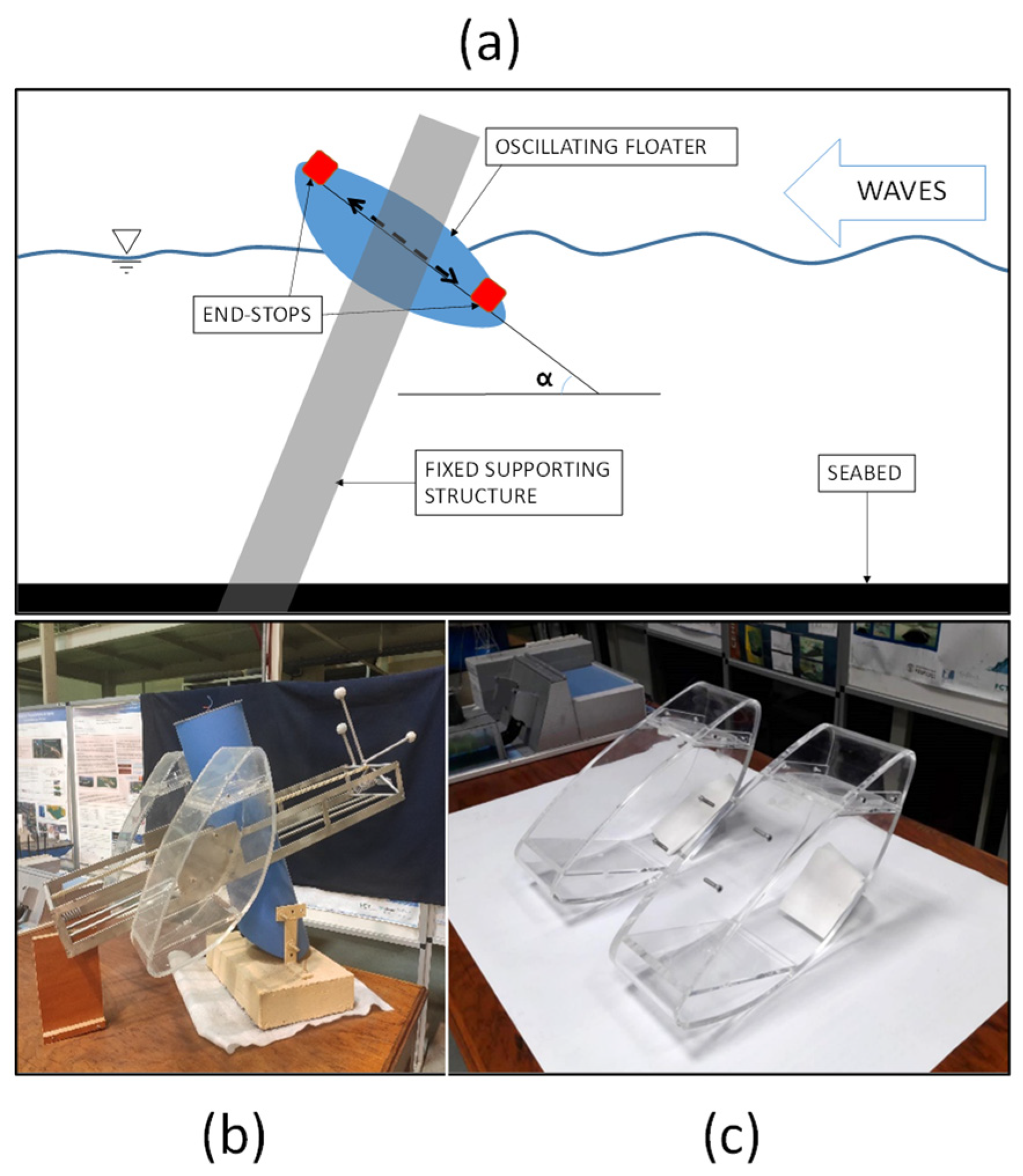
26]. The CECO is an oscillating body WEC with a floating block element (FBE) that swings along an inclined direction and activates a rotating generator located inside a supporting pile (
Figure 2a). Tuning the angle of inclination (
) of the FBE allows an adjustment of the device’s natural response period without varying its mass or using additional components such as springs. Such a characteristic is an advantage, allowing smaller floaters and a simplified concept with minimal components.
The CECO concept was developed and proved by means of numerical studies, e.g., those in [
28,
29,
30,
31], and experimental tests at the hydrodynamic wave basin available at the hydraulic laboratory of the FEUP using a physical scaled model [
32]. Numerical models based on PFM, i.e., WAMIT and ANSYS AQWA, were used to investigate the optimal linear PTO damping coefficients and the best FBE geometry [
7,
28,
33]. Moreover, experimental work allowed the obtainment of data for the validation of the numerical models.
Figure 2b,c show a second version of the CECO physical model (1/25 scale) with an improved floater geometry. The model was extensively tested at the hydraulic laboratory. Overall, it was positively concluded that the CECO concept could provide a capture width ratio above 35% for the typical sea states of the northern Portuguese coast [
22,
32].
On the other hand, the main drawback of the original CECO design is that it requires end-stops to constrain the motion of the FBE. Since extreme wave heights and subsequent high loads are expected for the water depths of the potential installation sites, end-stops are critical components from a structural perspective. The search for a reliable and cost-effective end-stop solution may be a very challenging task. Until now, no specific hydrodynamic load investigation has been carried out for the CECO device.
2.2. Novel PWEC Concept
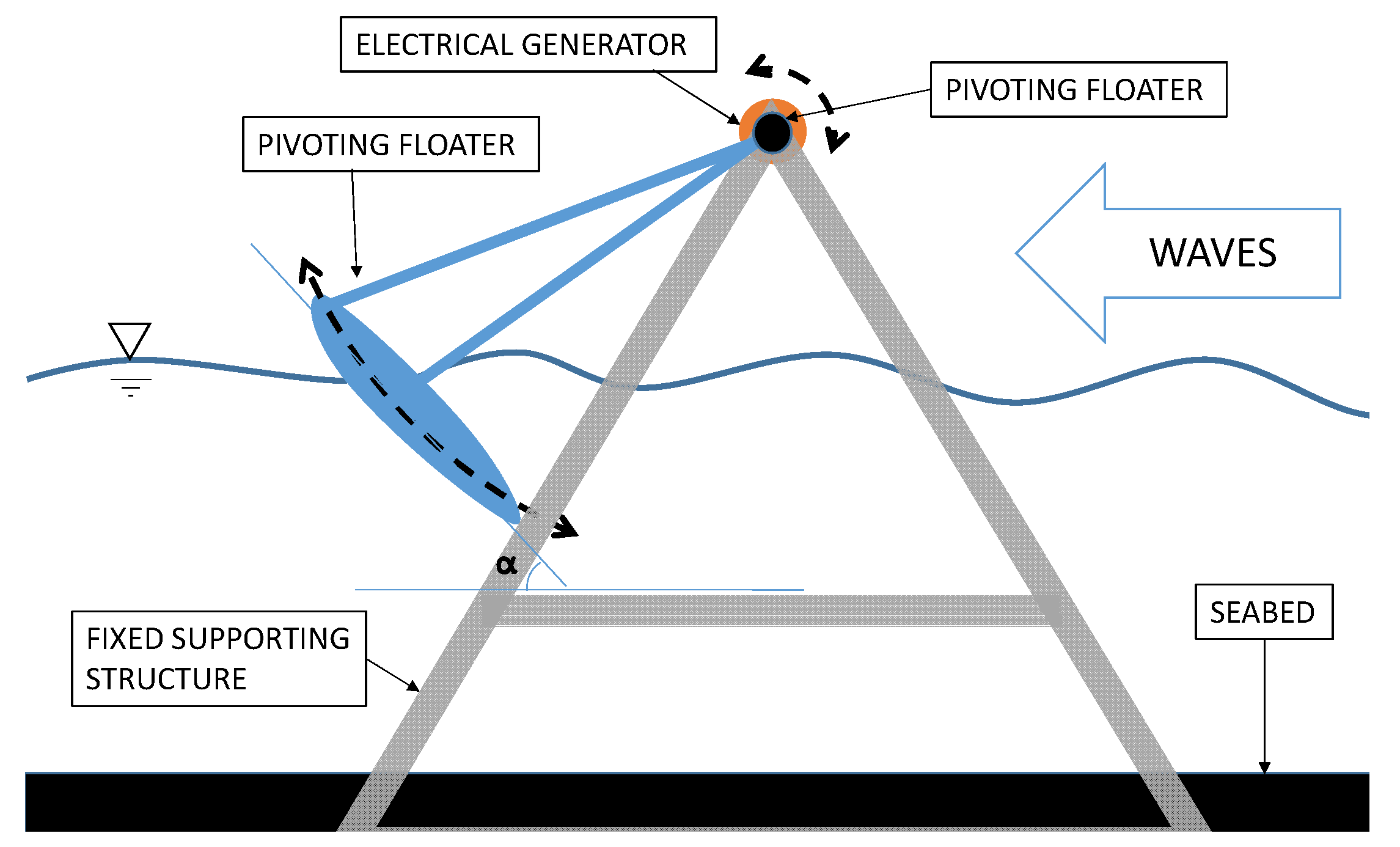
To overcome the issues related to the end-stops, a pivoting WEC (PWEC), inspired by the CECO is proposed (
Figure 3) [
27]. The PWEC aims to keep the CECO’s performance advantages regarding wave energy absorption due to its FBE oscillatory direction, whilst providing a solution without end-stops. The PWEC has a similar FBE but is a single floater (instead of two floaters as in the CECO) that, together with its holding frame (HF), rotates around a central point that is located at the top of a main fixed supporting structure (FSS) (
Figure 3). The swinging motion of the FBE activates a rotatory generator located at the rotational axis at the top of the FSS. For recurrent sea states (of limited wave amplitudes), both devices oscillate approximately along a line that has an inclination
with the horizontal frame, enhancing resonance and power performance (
Figure 2a and
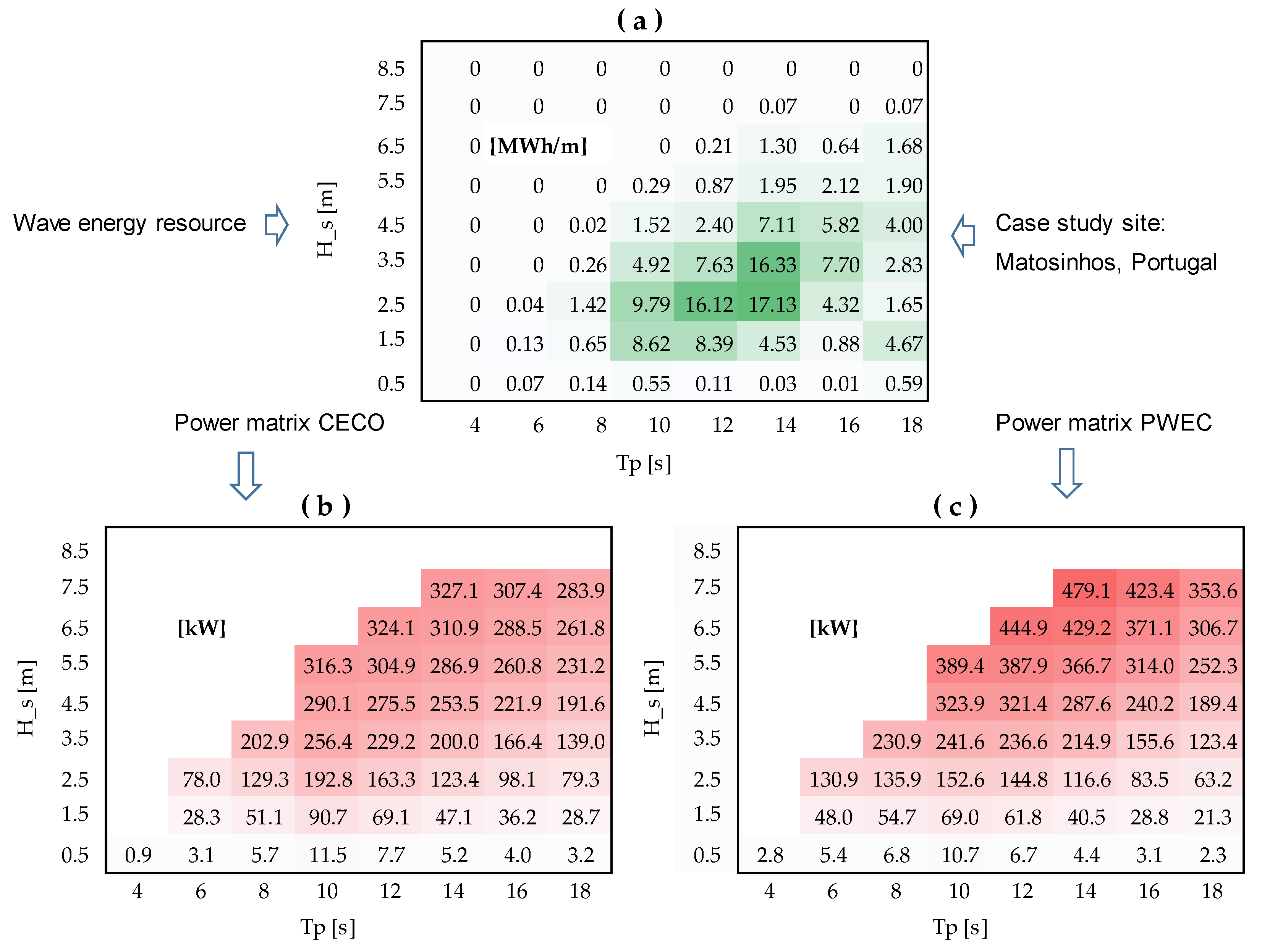
Figure 3). By means of numerical modelling, it was found that, besides having structural advantages, the PWEC’s FBE also has larger oscillations, since there are no end-stops, often allowing extra power to be absorbed with respect to the original CECO. As an illustration,
Figure 4 shows (a) the wave energy resource for the previous case study of Matosinhos, Portugal (in the proximity of the Port of Leixões, coordinates: 41.176237 N, 8.712030 W), (b) wave power matrices for the CECO, and (c) the PWEC. It can be observed that starting from 3.5 m Hs sea states, the PWEC can produce more power in most sea states. However, existing power absorption estimations were obtained by considering linear PTO. Investigations are required to include PTO control to further maximize the PWEC’s power absorption. Additionally, a previous preliminary economic analysis [
27] indicated that the PWEC, compared to the CECO, could be more viable due to the possible capital costs (28% saving) and estimated payback period (about 2.5 years less) reductions.
2.3. Storm Survival Mode
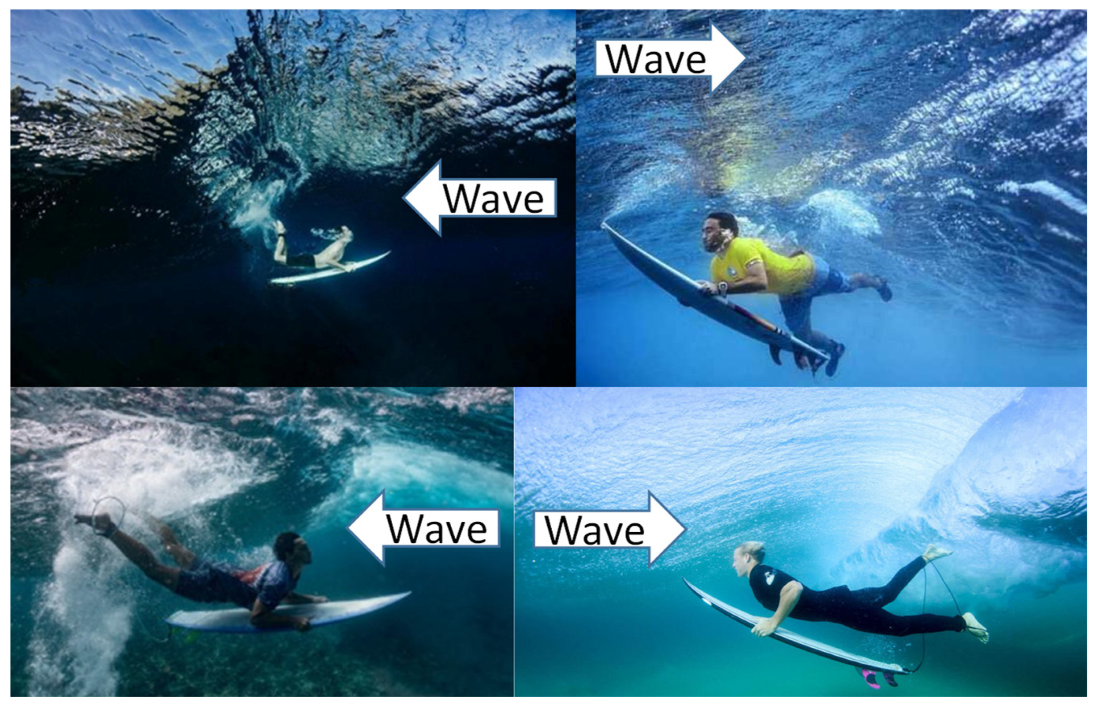
The geometric characteristics of the PWEC’s design allow the implementation of a survival mode of operation, giving it a potential additional advantage over the CECO concept. This survival mode was inspired by the duck dive maneuver of the surfing water sport (
Figure 5). The duck dive is performed by surfers to reduce wave loads over their bodies when paddling with their surfboards away from the shore. During good surfing conditions, the proficient execution of the duck dive maneuver is indispensable. Failure to perform this technique correctly may result in the surfer being either carried back to the shoreline or swept away by the prevailing water currents. The duck dive concept is similarly applied to PWEC for reducing the wave loads during extreme conditions.
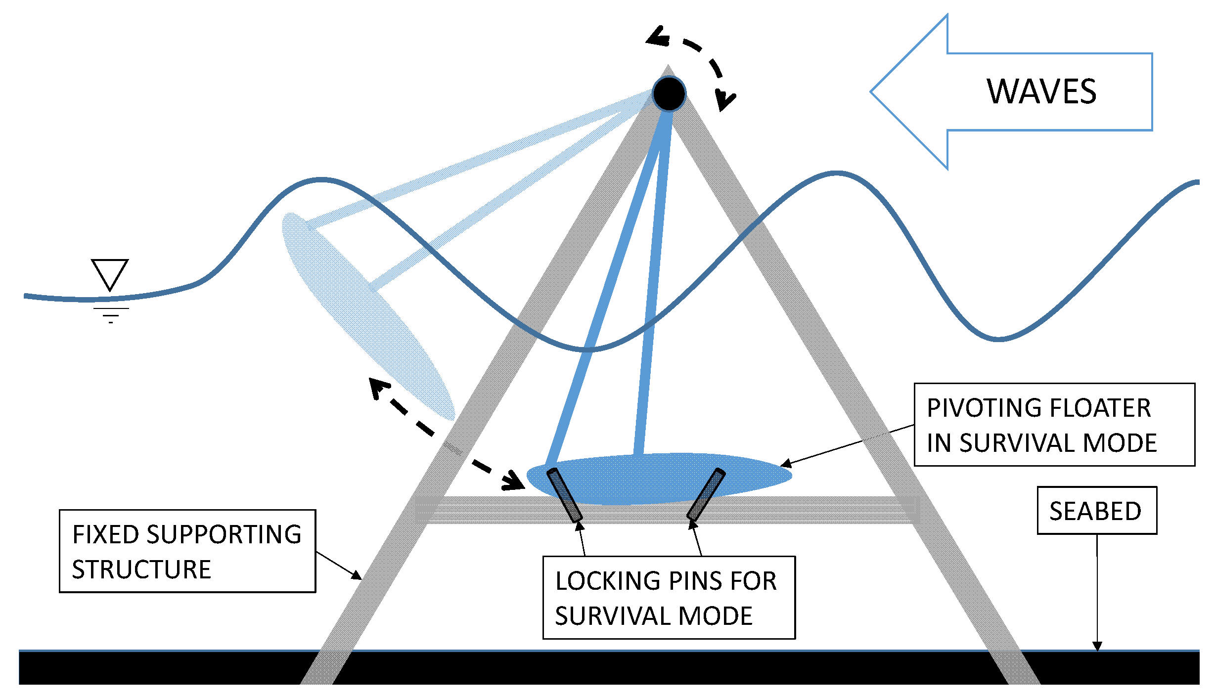
The proposed survival mode, illustrated in
Figure 6, is implemented only during the occasionally occurring extreme sea states. In this mode, after the device forecasts extreme sea states conditions, it automatically rotates the FBE to a low position and secures this to the FSS by underwater electrically activated pins. Such a survivability mode is expected to imply significantly reduced wave loads over the HF and FBE itself.
2.4. Hydrodynamic Model
For the main scope of the present study, wave loads during extreme sea states need to be numerically investigated to assess the effectiveness of the proposed innovative survival mode. The radiation diffraction theory can be used to set up the numerical model of the PWEC. The model is based on sequentially coupled frequency and time domain calculations. The dynamic problem can be described by Equation (1).
where
is the mass of the FBE plus its added mass,
is the FBE acceleration,
is the wave radiation force,
is the PTO force,
is the hydrostatic restoring force, and
are the wave forces.
Equation (1) for floating bodies is implemented by means of the theory introduced by Cummins [
18], which concerns the use of casual and non-casual convolution functions to compute the wave radiation and wave excitation forces. For the scope of this study, the body is assumed to be rigid; so, its flexibility is negligible, and it does not influence the calculation of loads and motions. The wave radiation force represents the force due to the floater motion that generates waves. This force can be estimated by a casual convolution function, such as the one presented in Equation (2).
where
is the kernel function calculated by using radiation damping coefficients and
is the added mass at infinite angular frequency (
).
Once the free surface elevation time series
is defined, the wave excitation force can be estimated by a non-casual convolution function, as represented in Equation (3).
where the transfer function
needs to be calculated using the wave excitation force coefficients. The dummy integral variables
and
of Equations (2) and (3) are arbitrarily chosen short-time values. Such variables need to be sufficiently long to correctly assess the hydrodynamic effects. In the case of small WECs such as the PWEC, casual and non-casual transient functions usually decay in about 30 s to 120 s, respectively [
20].
The PTO term (
) is assumed to be a linear term, as represented in Equation (4).
where
is the damping constant and
is the FBE’s velocity. Previous methodologies demonstrated that selected
values can be used to improve performance for each different sea state [
34].
The calculations were carried out with the commercial software ANSYS AQWA, implementing the radiation diffraction theory and considering the Wheeler stretching technique to estimate 2nd-order wave loads [
16]. Such an approach is adopted as a preliminary means of assessing the survival mode of the PWEC. The wave load numerical results are compared with measurements from experimental testing carried out at the hydraulic laboratory. A number of cases are analyzed, including scenarios where the FBE is assumed locked in place or in operation and different sea states.
2.5. Physical Model of PWEC
A simplified scaled physical model of the PWEC was manufactured, assembled, and tested to validate the concept and design. A scaling factor (SF) of 1:20 was adopted, considering the wave tank specifications and the available equipment. The chosen SF was reasonably large to estimate real-scale hydrodynamics, wave loads, and linear PTO absorption [
19]. For the considered type of WEC testing, the Froude scaling laws can be assumed to be satisfied. As discussed in [
35], the effects of viscosity can be predominantly found only near the water–body interface, making possible the use of Froude scaling. Generally, for simple WEC geometries, such as the FBE of the PWEC, which has a small ratio of wetted to volume areas, the viscous force influence is limited if compared with inertial forces. Such a characteristic supports the application of Froude scaling, which assumes the same ratio of inertial forces to gravitational forces between the full scale and model scale. Froude scaling is the primary option and is usually adopted in WEC testing [
36].
The main dimensions of the model are provided in
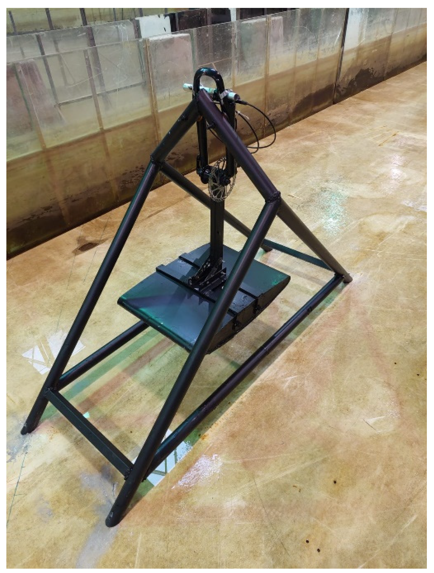
Figure 7. The supporting structure of the physical model was constructed by welding steel tubes (scaffolding tubes), and a bicycle fork was secured to the FSS replica,
Figure 8. A scaled FBE was linked by a bicycle hub inserted in the bicycle fork (
Figure 9). The FSS was secured to the tank floor using fixing screw anchors.
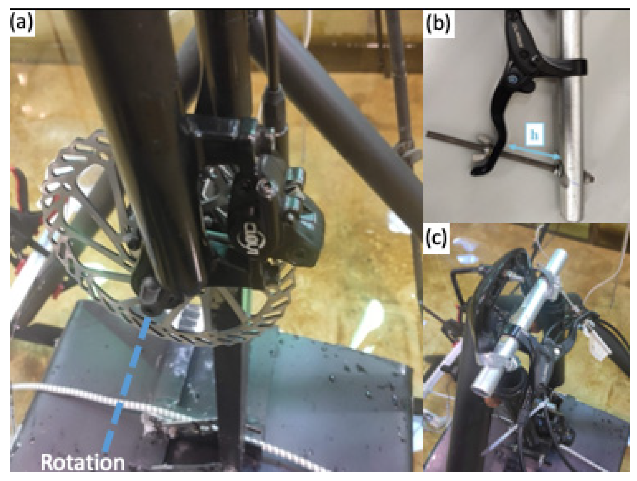
A bicycle fork with a hub and hydraulic disk brake arrangement facilitated precise and low friction rotation of the FBE element, while also integrating an adjustable brake to replicate the rotational PTO force. The fork was firmly bolted to the FSS at an upper location so that the rotational axis coincided with the top corner of the FSS (
Figure 9a).
The brake replicated a scaled PTO force, providing mechanical energy dissipation. The PTO load magnitude was tuned by a lever secured in place by means of a bolt and nuts (
Figure 9b). A caliper was used to measure the closing distance of the lever,
h, to improve PTO load repeatability. The lever was attached firmly to the FSS of the model to avoid twisting the brake cable and affecting the quality of the replicated PTO force (
Figure 9c).
2.6. Experiment Set-Up and Instrumentation
The PWEC physical model was tested at the ocean basin of the Hydraulic Laboratory of the Department of Civil Engineering of FEUP, which is 28 m long, 12 m wide, and 1.2 m deep. The basin is equipped with 16 piston-like paddles to produce waves. A Wallingford wave maker system with wave reflection absorption functionality controls all the paddles. For this work, the water depth was set to 0.6 m, and the model was tested in a section of the basin with a width equal to 4 paddles (~3.07 m).
Figure 10 illustrates the location of the model with respect to the wave maker (on the right) and the dissipation beach (on the left).
For the scope of the study, a single PTO damping value was used to assess the FBE response to wave loads. The PTO damping was calibrated by dry oscillation tests using a mass (
Figure 11). The pendulum equation was used to tune the target damping value (11.2 kg/s). The differential equation that characterizes the kinematic motion of a damped pendulum can be expressed by Equation (5):
where
is the angle between the vertical and the holding arm,
is the time,
is the oscillating mass,
L the radius of the pendulum, and
is the damping coefficient, expressed as:
where
is the damping factor and
is the equivalent force constant.
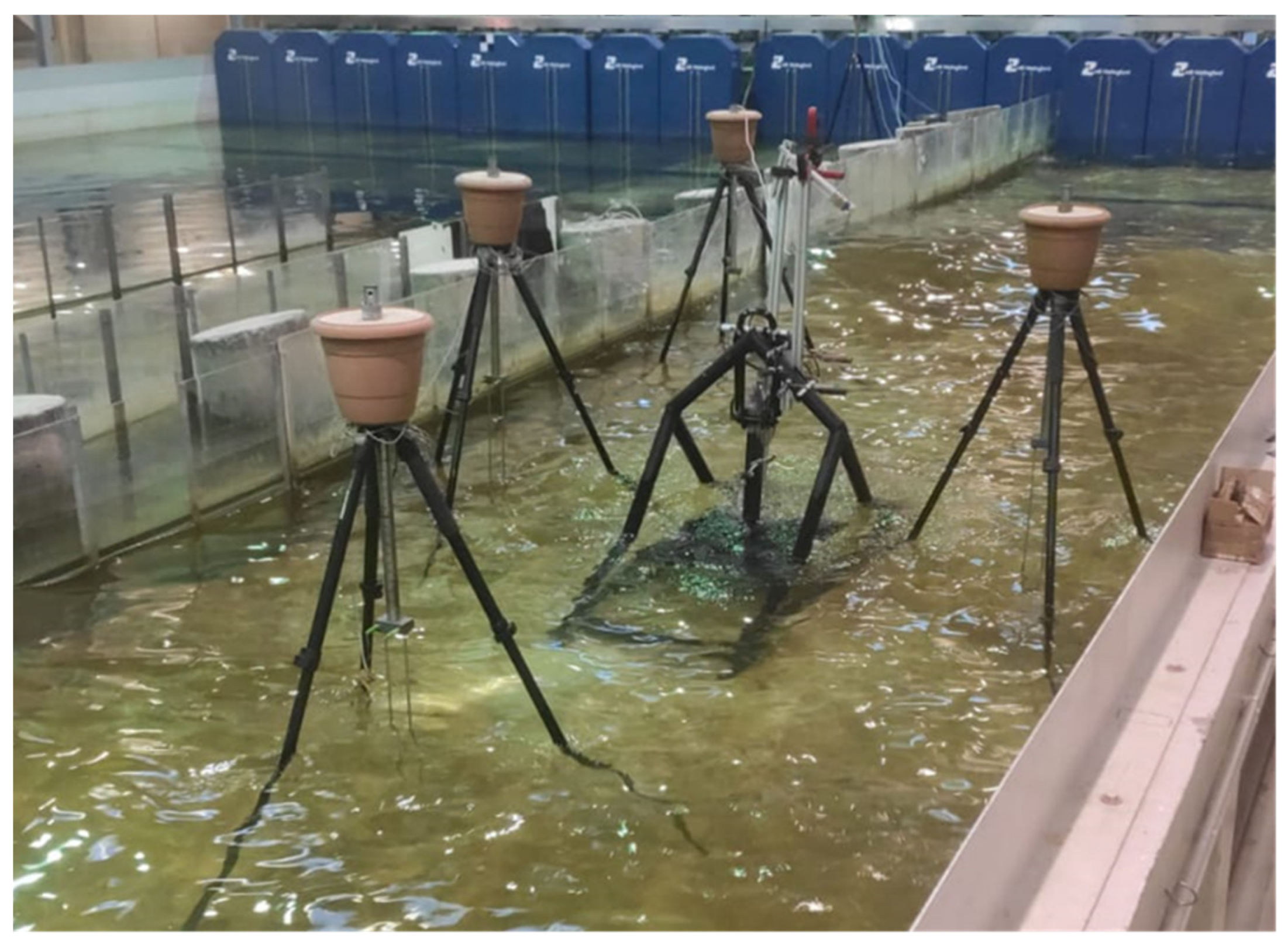
Four resistive wave probes were set up to monitor the free surface elevation (
Figure 10 and
Figure 12). Two wave probes were positioned laterally to the model to assess the incident waves to the structure. In addition, the two other wave probes, for monitoring the effect of the model on the wave field, were installed upstream and downstream of the model, respectively.
The Qualisys system [
37], which uses infrared cameras for accurate motion tracking, was used to measure the PWEC’s response. Three Qualisys cameras were positioned around the PWEC model (
Figure 13).
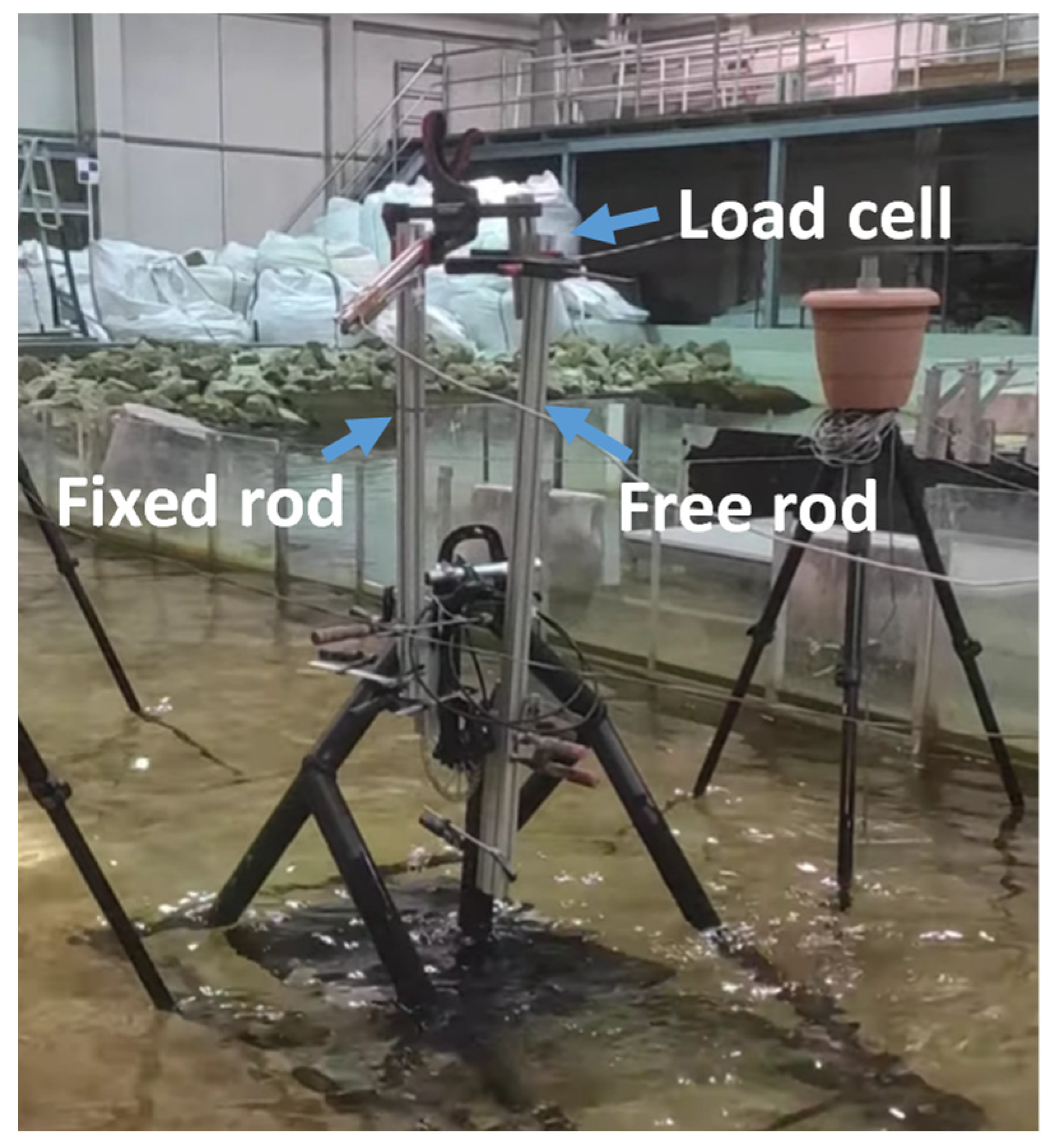
For the tests performed with the FBE locked in place (survival mode), the wave-induced load (horizontal direction) was assessed by means of a 10 kg load cell. An extension of the arm holding the floater was used to install the load cell out of the water and hence improve the quality of the measurements (
Figure 14).
All the instruments used for the measurements were calibrated following the manufacturers’ guidelines and recommended practices [
19,
35].
3. Results
Both the experimental and numerical tests were carried out to assess the PWEC in operational (moving), standard position (locked in place), and survival (locked in place) conditions, as shown in
Figure 15 (a, b, and c, respectively). The scope of the analysis was to verify the numerical model and to evaluate the FBE’s response and wave loads. The main test conditions adopted in the present study are summarized in
Table 1.
The outputs of the analysis are the response amplitude operators (RAOs), Froude–Krylov, diffraction, total hydrodynamic forces (horizontal and vertical components), and load cell measurements.
3.1. FBE in Operation
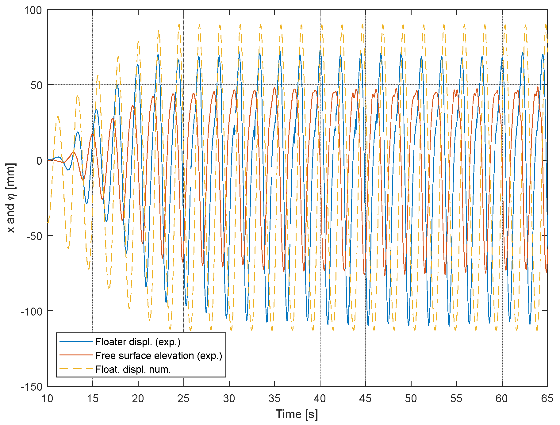
At first, regular waves were used to evaluate the response of the device and validate the numerical model results. As illustrated in
Figure 16, accurate regular waves can be produced at the wave basin. This figure shows the time series of the FBE linear displacement
(along the curved trajectory) obtained by experimental measurements, the free surface elevation
(from wave probes), and
from the numerical simulations. This test represents a typical wave period of the Portuguese coast (10 s at full scale). Furthermore, upon examination of various regular wave tests, including those with periods of 10, 11, and 12 s, it can be observed that the numerical predictions match empirically with the RAOs, with an accuracy level of approximately 18% (
Figure 17). Considering the limitations of both the numerical model (linearization) and the experimental set-up (model-making precision), such an accuracy level appears to be of reasonable value.
As can be observed from the regular waves and RAO results (e.g.,
Figure 16 and
Figure 17), thanks to the identified experimental set-ups, the calibration procedures, and the instrumentation used, single waves and test repeatability were achieved. In terms of RAOs, for the regular waves, the experimental results could be repeated with an estimated error of less than about 10%.
As illustrated in
Figure 18, the FBE oscillates from about 400 mm to 600 mm for the irregular wave tests. During larger waves, oscillations can reach up to about two times the amplitude of the approaching wave. From the presented results, it can also be observed that the numerical model predicts the motion of the FBE with some overestimation (no more than 40% but just during larger oscillations). This most likely happens due to the limitations of the numerical model, which does not consider additional viscous (hydrodynamics forces) and friction (model set-up-related) forces. For such a comparison, the same free surface elevation (measured in laboratory) was input to run the numerical test.
3.2. Assessment of Survival Mode with Regular Waves
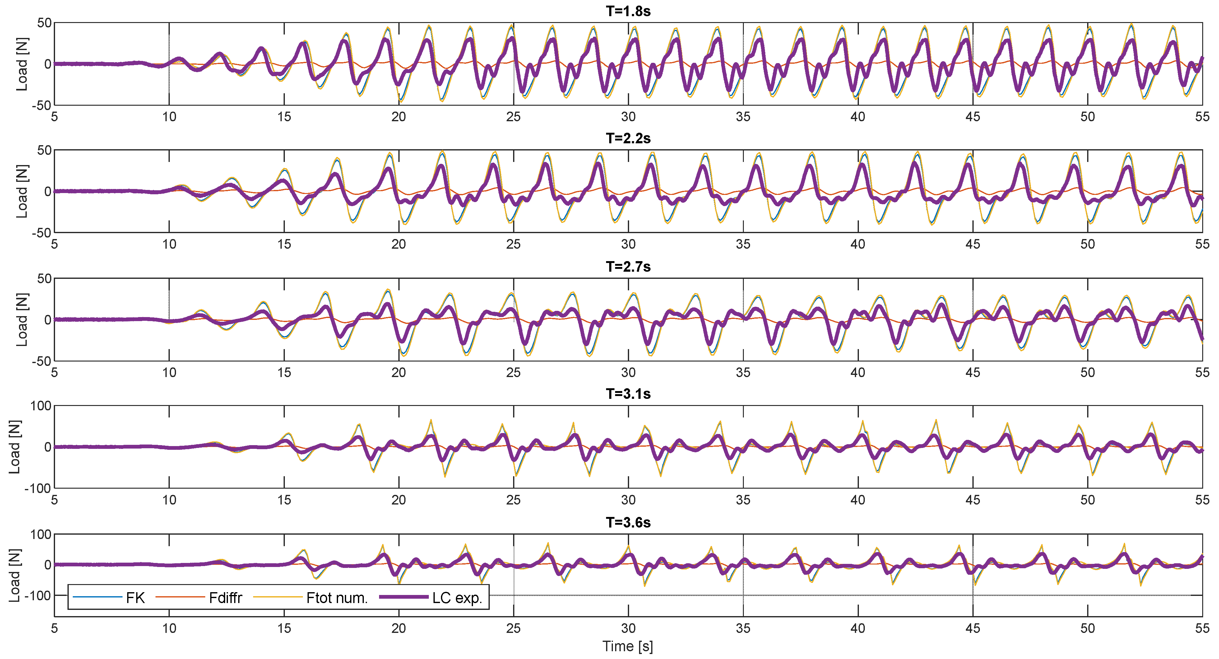
For assessment and proof of concept of the survival mode of the PWEC, the horizontal wave loads were estimated by means of numerical and experimental tests (
Figure 19), where the numerical and experimental time series of the Froude–Krylov (FK), diffraction, total force, and measured load (load cell data from the experiment) are displayed, respectively. Here, the results for five regular wave tests of H = 0.2 m, T = 1.8 s, 2.2 s, 2.7 s, 3.1 s, and 3.6 s are shown. It can be observed that, despite the peak values being overestimated by the numerical model, the numerical time series are comparable to the measured load pattern.
In
Table 2, the maximum numerical and experimental values are compared to quantify the accuracy of the numerical model. The root mean square error (RMSE), mean absolute error (MAE), and R-squared (R
2) indexes were calculated to evaluate the difference between the time series of the total force (diffraction and Froude–Krylov) and the numerical model and the measured load. For the analyzed test cases, RMSE, MAE, and R
2 were on average 13.21, 8.82 N, and 0.64, respectively.
Based on the experimental facility characteristics and limitations and on the experimental results obtained, five regular wave tests were carried out for assessing wave loads on the FBE (
Table 3). The horizontal component of the survival mode set-up, measured during the experiment, contributed to the assessment of the model for these wave conditions. The numerical model does not have the limitation of the experiments; so, it can be used to compute other quantities for survival and standard positions.
Figure 20 reports the wave load results for the horizontal and vertical components of FK, F_diff, and their resultant total. It can be observed that, in the large majority of load components assessed, the survival mode is beneficial in reducing wave loads. It was found that the total wave load on the FBE in the survival mode for all the RW tests was about 40% less than for the standard position.
Despite the fact that the simpler regular wave tests facilitated the carrying out of the initial experimental assessments and initial analysis (e.g., RAOs assessment), ocean conditions are better represented by means of irregular wave sea states. Therefore, following the RW experimental and numerical tests, irregular wave tests were used to evaluate the PWEC’s wave loads and motions. For the scope of the study, as for RW, only unidirectional irregular sea states were considered.
3.3. Irregular Wave Load Results
Irregular wave tests are required to assess the FBE behavior and loads for a broader range of waves representing more realistic conditions. As illustrated in
Table 4, five irregular wave (IrrW) conditions were analyzed, i.e., H
s = 0.2 m, T
p = 2.24 s, 2.68 s, 3.13 s, 3.58 s, and 4.02 s (laboratory scale). At full scale, these sea states correspond to wave conditions with considerable power. The JONSWAP sea spectrum [
38], suitable for the Atlantic region with the parameter
, was adopted for creating IrrW conditions. The three possible modes of PWEC, namely survival (locked in place), standard position (locked in place), and operational (moving condition), are assessed. For the operating condition, a PTO damping value equal to 530,000 kg/s is assumed based on a previous study [
27].
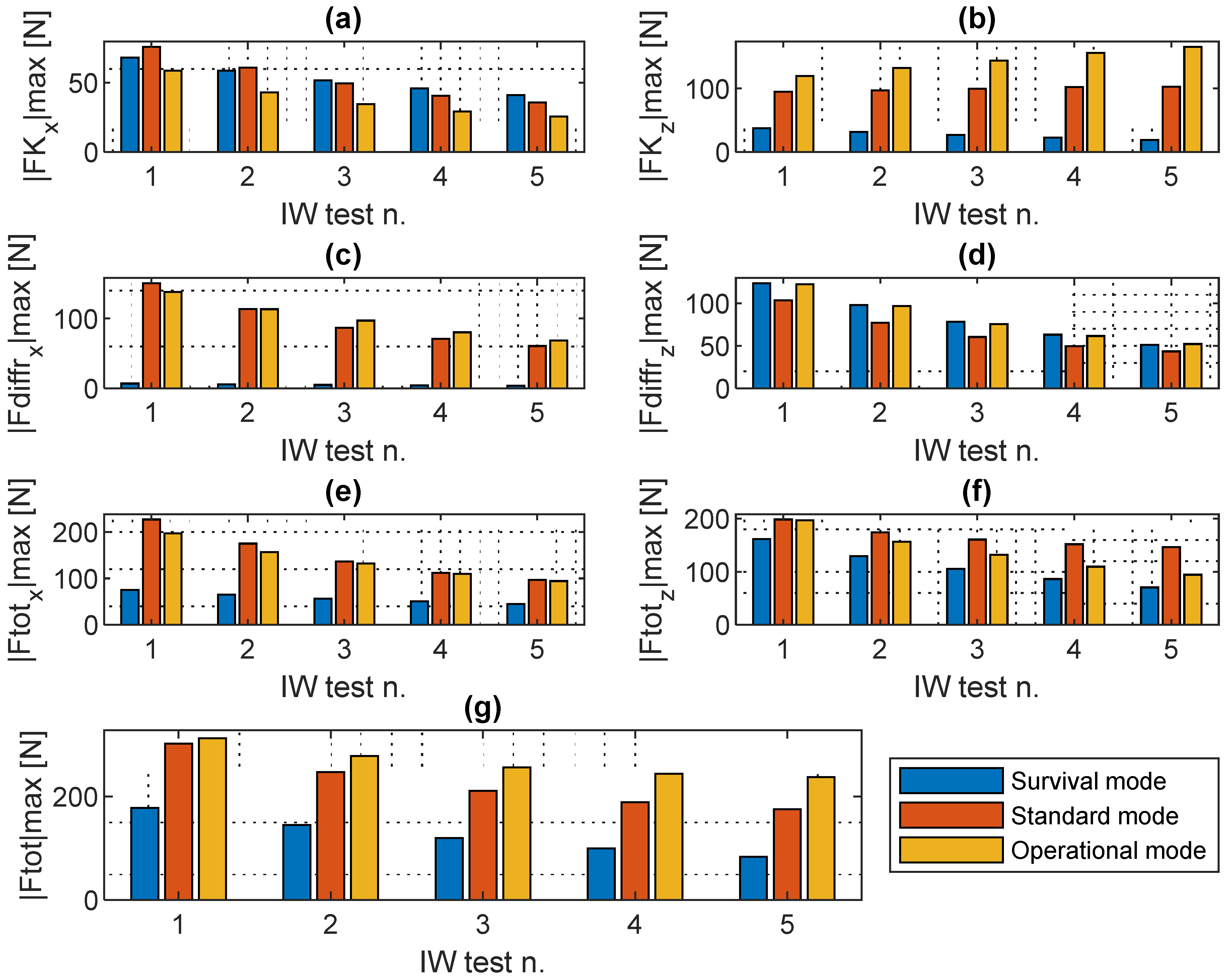
As for RW, the FK, diffraction, horizontal and vertical components, and resultant forces are analyzed (
Figure 21). Except for the FK horizontal and diffraction force vertical components, significantly reduced loads are observed for the survival mode. Similarly, as for the RW load results, for IrrW, only in the case of the vertical component of the diffraction force are the loads markedly higher for the survival mode. The survival mode is also found to be experiencing a higher FK horizontal load for IrrWs 3 to 5. In any case, the total horizontal and vertical loads are always reduced for the survival mode.
The survival mode experiences less than about 40% of total load with respect to the standard and operational modes. The operational mode experiences a load about 20% higher than the standard mode.
4. Discussion
Given the limitations of the developed approach, which is specifically related to the type of numerical model selected, the present analysis should be considered as a preliminary work focusing on the assessment of the PWEC’s survival mode. In fact, the adopted numerical model does not include viscosity-related hydrodynamic forces, but it must be highlighted that the experimental results confirm the numerical assumptions. Despite this validation of the numerical results, it is important that in a later stage of development, the viscous forces are fully assessed by using CFD models and performing additional experimental testing. This additional testing should include smaller physical models or bigger wave tanks where larger waves can be accurately simulated. Such assessment can be carried out with extreme waves to evaluate hydrodynamic loads, including the viscous forces that are expected to be relevant in such conditions. Only when the accurate calculation of both viscous and inertial wave loads is completely implemented, should the full-scale structure design be developed.
Moreover, to validate the survival mode fully, supplementary numerical simulations and experimental testing should also be carried out by means of more realistic extreme sea states, derived from historical real sea data and improved physical model set-ups. It was not possible to prove these scenarios due to the limitations of the numerical model and the experiment set-up/facility used. To improve the validation of the survival mode with more realistic sea states, it is necessary to perform additional specific testing by manufacturing and using a reduced physical model and a more advanced experimental set-up to accurately measure wave loads for all three of the modes considered in the present study.
Furthermore, it is important to point out that the present study focuses only on the assessment of the survival mode carried out by evaluating the hydrodynamic loads once the device is in specific positions. Supplementary assessments are required to validate several additional aspects related to the implementation and operation of the survival mode mechanism, including the structure components’ reliability and control of the device to operate the survivability mode. For such analysis and additional validations, it is suggested to carry out extra specific experimental tests using components such as a locking mechanism, floater ballasts, and an active PTO system. Additionally, fatigue analysis is required for the structural design of the components required to implement the survivability mode. The developed time domain potential flow model, given its computational efficiency, can facilitate such analysis because it can provide long-term wave load data.
In the present study, only a set of regular and irregular sea states were assessed to evaluate the survival mode. Currently, the specifications of the extreme sea states that should trigger this mode have not been identified yet. To determine these critical sea states and assess the commercial viability of the survival mode mechanism, more advanced tests—including those involving subcomponents—should be conducted based on the specific installation site and final PWEC prototype characteristics. A combined cost analysis and structural design optimization should be performed to determine the thresholds at which the survival mode should be activated. Implementing the survival mode could be significantly advantageous for reduced pre-commercial PWEC pilot plans (e.g., 1:2 scale) to ensure device resilience during sea trials. Given that these plans typically involve limited sea testing time and the device design is not yet finalized, activating the survival mode at reduced sea states would allow safer testing of the PWEC. In fact, the survival mode could also be activated during sea states that are not necessarily the extreme, but at any time when may be required, manually or automatically, e.g., when live measured parameters reach specific set thresholds.
In addition to the technical aspects that need to be further developed towards PWEC commercialization, environmental impact assessments (EIAs) need to be carried out to ensure that a possible installation of such technology will not harm the marine environment. A review of the EIAs for WEC projects can be found in [
39]. Even though the PWEC, as with other WECs, is a renewable energy device that would provide clean power and has advantages even when compared to other renewables (e.g., less visual impact than wind turbines and higher energy density), there are several potential environmental impacts that should be investigated. The EIA should be tailored to installation location characteristics and carried out for each planned implementation project. For example, for all the PWEC’s modes of operation (normal, standard, and survival), the following EIA should be carried out considering the following specific possible impacts:
Marine ecosystems and marine life;
Natural sediment transport and erosion modification through changes in the local hydrodynamic conditions;
Lubricant contamination (limited for the PWEC because the PTO is outside water);
Antifouling submerged structure degradation contamination;
Installation works.
Furthermore, additional economic and cost-benefit analysis should be carried out for the PWEC and its survival mode mechanism to validate its commercial viability. To date, only preliminary economic indexes have been considered for understanding capital costs and payback periods without considering survival mode mechanisms [
27]. At later stages, it is important to investigate design solutions for implementing the survivability mode using locking pins and to evaluate the manufacturing, maintenance, and operating costs, including those of the major device components. A cost-benefit analysis, including manufacturing, materials, electrical components, installation, and maintenance costs, is required to accurately compare the solution with other similar devices. Such an analysis will not only allow a better understanding of the economic viability of the PWEC but will also serve to identify critical expenses that need to be reduced to make the PWEC technology and its deployments more competitive.
5. Conclusions
The study described represents an initial assessment of the potential of the PWEC (Pivoting Wave Energy Converter) device, with a particular focus on the evaluation of an innovative survivability mode. Through a combination of numerical and physical modelling, the effectiveness of this mode in reducing wave loads on PWECs was investigated across a range of wave conditions. Three different modes, namely operational, standard position, and survival, were compared in terms of loads on the main floating body element of the device (FBE).
The utilization of both numerical and physical models provided a comprehensive understanding of PWEC behavior and wave loading. The numerical model, based on the potential flow theory, served as a theoretical framework for the three mode assessments, while physical testing at a reduced scale allowed the verification of the numerical approach adopted.
Experimental set-ups and calibration methods, suitable for assessing rotating WECs, were instigated. The most suitable ones were identified and implemented for the assessment of motion and loads on the PWEC. By the adopted physical modelling, good repeatability was possible, e.g., with repeated RAOs varying less than 10%. Such experimental set-ups and methods, can be adjusted to be further adopted during additional physical modelling-based studies on similar devices.
The findings revealed promising outcomes regarding the efficacy of the survival mode in mitigating wave-induced loads on the floating body element (FBE) of the PWEC. In both the regular and irregular wave scenarios, significant reductions in the total horizontal loads were observed compared to the standard and operational modes. Specifically, reductions of up to approximately 40% and 65% were demonstrated in comparison to the standard positioning and operational modes, respectively.
Furthermore, the limitations of the method applied and the critical future work to improve the results and further develop the PWEC were discussed. The main limitations of the current preliminary analysis mainly relate to the type of numerical model implemented and the neglected viscosity. To overcome these limitations, additional numerical and experimental testing approaches are necessary, including the use of more realistic sea states derived from in situ measured and/or propagated wave data. In addition, assessments including specific required components and PTO control should be carried out to validate fully the survival mode of the operation and should not be limited to the simplified scenario assessed in the present study. Moreover, environmental impact and economic assessments are required to anticipate possible obstacles and identify challenges that require attention to ensure marine environment impact minimization and the PWEC’s economic viability for commercialization.
The outcomes of the present study go beyond the scope of the specific PWEC device, offering insights and directions for future research in wave energy. Moving forward, the following areas require further exploration: (i) Refining numerical modelling, including CFD analysis, to precisely assess the hydrodynamic forces on the PWEC components; (ii) enhancing methodologies for structural design and reliability assessment to ensure durability in diverse marine environments; (iii) implementing PTO control strategies to maximize energy absorption under varying sea conditions, particularly during recurrent and extreme events; (iv) including factors such as PTO control strategies and tide variations in AEP estimations for more accurate assessments; (v) conducting additional experimental validations and demonstrations to validate findings and refine predictive models; (vi) exploring novel methods for seabed fastening and foundation protection to ensure stability and resilience of PWEC installations; (vii) conducting holistic techno-economic assessments and cost-benefit analysis and also considering various operational aspects, including the survival mode mechanism, with the aim of optimizing the design and validating its commercial viability.
These paths of research will further advance the PWEC technology and also help similar oscillating types of WECs to reach commercialization.
Author Contributions
Conceptualization, G.G.; methodology, G.G.; formal analysis, G.G.; investigation, G.G., V.R., E.Z., T.C.-C., I.I. and P.R.-S.; resources, G.G., V.R. and P.R.-S.; data curation, G.G.; writing—original draft preparation, G.G.; writing—review and editing, P.R.-S., F.T.-P., V.R., I.I. and T.C.-C.; visualization, G.G.; supervision, P.R.-S. and F.T.-P.; project administration, G.G., P.R.-S. and F.T.-P.; funding acquisition, G.G., P.R.-S. and F.T.-P. All authors have read and agreed to the published version of the manuscript.
Funding
The authors would like to thank the financial support from: the project PORTOS—Ports Towards Energy Self-Sufficiency (EAPA 784/2018), co-financed by the Interreg Atlantic Area Programme through the European Regional Development Fund, and the project RPWEC—Reliable Pivoting Wave Energy Converter (CIIMAR SEED 2023-24 project). G.G., V.R. and I.I. would like to acknowledge the financial support received through the Stimulus of Scientific Employment program of the Portuguese Foundation of Science and Technology (FCT), specifically via the individual grants referenced by 2022.04954.CEECIND, CEECIND/03665/2018, and 2022.07420.CEECIND. Furthermore, for this work, E.Z. has been supported by the FCT PhD scholarship grant n. 2023.01289.BD and T.C.C. by the FCT PhD scholarship grant 2021.07687.BD. The authors also want to acknowledge the CIIMAR Strategic Funding UIDB/04423/2020 and UIDP/04423/2020 financed through national funds provided by the FCT and the European Regional Development Fund (ERDF).
Data Availability Statement
The original contributions presented in the study are included in the article, further inquiries can be directed to the corresponding authors.
Conflicts of Interest
The authors declare no conflicts of interest.
References
- Gunn, K.; Stock-Williams, C. Quantifying the global wave power resource. Renew. Energy 2012, 44, 296–304. [Google Scholar] [CrossRef]
- Reguero, B.G.; Losada, I.J.; Mendez, F.J. A global wave power resource and its seasonal, interannual and long-term variability. Appl. Energy 2015, 148, 366–380. [Google Scholar] [CrossRef]
- IEA. Energy Data Statisics from the International Energy Agency. 2022. Available online: https://www.iea.org/data-and-statistics (accessed on 24 April 2024).
- OpenEI. Marine Energy Projects Database. Wave Energy Projects. 2024. Available online: https://openei.org/wiki/PRIMRE/Databases/Projects_Database (accessed on 24 April 2024).
- Wave Star, A/S. Available online: http://wavestarenergy.com/ (accessed on 20 January 2023).
- Falcao, A.F.O.; Sarmento, A.J.N.A.; Gato, L.M.C.; Brito-Melo, A. The Pico OWC wave power plant: Its lifetime from conception to closure 1986–2018. Appl. Ocean Res. 2020, 98, 102104. [Google Scholar] [CrossRef]
- Giannini, G.; Lopez, M.; Ramos, V.; Rodriguez, C.A.; Rosa-Santos, P.; Taveira-Pinto, F. Geometry assessment of a sloped type wave energy converter. Renew. Energy 2021, 171, 672–686. [Google Scholar] [CrossRef]
- Rosa-Santos, P.; Taveira-Pinto, F.; Rodríguez, C.A.; Ramos, V.; López, M. The CECO wave energy converter: Recent developments. Renew. Energy 2019, 139, 368–384. [Google Scholar] [CrossRef]
- Sarkar, D.; Doherty, K.; Dias, F. The modular concept of the Oscillating Wave Surge Converter. Renew. Energy 2016, 85, 484–497. [Google Scholar] [CrossRef]
- AW-Energy. Available online: https://aw-energy.com/waveroller/ (accessed on 16 June 2023).
- Henry, A.; Power, U.A.; Doherty, K.; Cameron, L.; Doherty, R.; Whittaker, T. Advances in the Design of the Oyster Wave Energy Converter. In Proceedings of the RINA Marine and Offshore Energy Conference, London, UK, 21–23 April 2010. [Google Scholar]
- Coiro, D.P.; Troise, G.; Calise, G.; Bizzarrini, N. Wave energy conversion through a point pivoted absorber: Numerical and experimental tests on a scaled model. Renew. Energy 2016, 87, 317–325. [Google Scholar] [CrossRef]
- Eco-Wave-Power. Available online: https://www.ecowavepower.com/ (accessed on 15 June 2023).
- Coiro, D.T.G.; Calise, G.; Bizzarrini, N. Experimental test and numerical shape optimization of a point pivoted absorber for wave energy conversion. In Proceedings of the VI International Conference on Computational Methods in Marine Engineering MARINE, Rome, Italy, 15–17 June 2015. [Google Scholar]
- WAMIT. WAMIT®—The State of Art in Wave Interaction Analysis. Available online: https://www.wamit.com/ (accessed on 15 April 2024).
- ANSYS. Aqwa Theory Manual. Canonsburg. 2015. Available online: https://ansyshelp.ansys.com/ (accessed on 29 November 2019).
- DNV-GL. SESAM DeepC Company Website. Available online: https://www.dnv.com/ (accessed on 10 January 2021).
- Cummins, W.E. The impulse response function and ship motions. Schiffstechnic 1962, 101–109. [Google Scholar]
- Giannini, G.; Temiz, I.; Rosa-Santos, P.; Shahroozi, Z.; Ramos, V.; Göteman, M.; Engström, J.; Day, S.; Taveira-Pinto, F. Wave Energy Converter Power Take-Off System Scaling and Physical Modelling. J. Mar. Sci. Eng. 2020, 8, 632. [Google Scholar] [CrossRef]
- Giannini, G.; Day, S.; Rosa-Santos, P.; Taveira-Pinto, F. A Novel 2-D Point Absorber Numerical Modelling Method. Inventions 2021, 6, 75. [Google Scholar] [CrossRef]
- Beatty, S.; Ferri, F.; Bocking, B.; Kofoed, J.P.; Buckham, B. Power Take-Off Simulation for Scale Model Testing of Wave Energy Converters. Energies 2017, 10, 973. [Google Scholar] [CrossRef]
- Rosa-Santos, P.; Taveira-Pinto, F.; Teixeira, L.; Ribeiro, J. CECO wave energy converter: Experimental proof of concept. J. Renew. Sustain. Energy 2015, 7, 061704. [Google Scholar] [CrossRef]
- Fernandez, H.; Iglesias, G.; Carballo, R.; Castro, A.; Fraguela, J.; Taveira-Pinto, F.; Sanchez, M. The new wave energy converter WaveCat: Concept and laboratory tests. Mar. Struct. 2012, 29, 58–70. [Google Scholar] [CrossRef]
- Shi, G.; Li, R.; Xiao, Q. Bio-inspired propulsion in ocean engineering: Learning from nature. In Proceedings of the MARINE VIII: Proceedings of the VIII International Conference on Computational Methods in Marine Engineering, Göteborg, Sweden, 13–15 May 2019; CIMNE. ISBN 8494919431, ISSN 8494919431. [Google Scholar]
- Usta, O. Numerical investigation on the resistance characteristics of nature inspired underwater vehicles. In Proceedings of the 2nd International Congress on Ship and Marine Technology, Istanbul, Turkey, 16–18 September 2021. [Google Scholar]
- Blanco, J.; Rodriguez, J.d.D.; Couce, A.; Lamas, M.I. Proposal of a Nature-Inspired Shape for a Vertical Axis Wind Turbine and Comparison of Its Performance with a Semicircular Blade Profile. Appl. Sci. 2021, 11, 6198. [Google Scholar] [CrossRef]
- Giannini, G.; Rosa-Santos, P.; Ramos, V.; Taveira-Pinto, F. Wave energy converters design combining hydrodynamic performance and structural assessment. Energy 2022, 249, 123641. [Google Scholar] [CrossRef]
- López, M.; Ramos, V.; Rosa-Santos, P.; Taveira-Pinto, F. Effects of the PTO inclination on the performance of the CECO wave energy converter. Mar. Struct. 2018, 61, 452–466. [Google Scholar] [CrossRef]
- López, M.; Taveira-Pinto, F.; Rosa-Santos, P. Numerical modelling of the CECO wave energy converter. Renew. Energy 2017, 113, 202–210. [Google Scholar] [CrossRef]
- López, M.; Taveira-Pinto, F.; Rosa-Santos, P. Influence of the power take-off characteristics on the performance of CECO wave energy converter. Energy 2017, 120, 686–697. [Google Scholar] [CrossRef]
- Ramos, V.; López, M.; Taveira-Pinto, F.; Rosa-Santos, P. Performance assessment of the CECO wave energy converter: Water depth influence. Renew. Energy 2018, 117, 341–356. [Google Scholar] [CrossRef]
- Rodríguez, C.A.; Rosa-Santos, P.; Taveira-Pinto, F. Experimental Assessment of the Performance of CECO Wave Energy Converter in Irregular Waves. J. Offshore Mech. Arct. Eng. 2019, 141, 041903. [Google Scholar] [CrossRef]
- Rodríguez, C.A.; Rosa-Santos, P.; Taveira-Pinto, F. Hydrodynamic optimization of the geometry of a sloped-motion wave energy converter. Ocean Eng. 2020, 199, 107046. [Google Scholar] [CrossRef]
- Giannini, G.; Rosa-Santos, P.; Ramos, V.; Taveira-Pinto, F. On the Development of an Offshore Version of the CECO Wave Energy Converter. Energies 2020, 13, 1036. [Google Scholar] [CrossRef]
- Payne, G. Guidance for the experimental tank testing of wave energy converters. In SUPERGEN Marine Project; University of Edinburgh: Edinburgh, UK, 2008. [Google Scholar]
- Heller, V. 8.04—Development of Wave Devices from Initial Conception to Commercial Demonstration. In Comprehensive Renewable Energy; Sayigh, A., Ed.; Elsevier: Oxford, UK, 2012; pp. 79–110. ISBN 978-0-08-087873-7. [Google Scholar] [CrossRef]
- QUALISYS. Qualisys Motion Capture System. 2024. Available online: https://www.qualisys.com/ (accessed on 28 April 2024).
- Hasselmann, K.; Barnett, T.P.; Bouws, E.; Carlson, H.; Cartwright, D.E.; Enke, K.; Ewing, J.A.; Gienapp, H.; Hasselmann, D.E.; Kruseman, P.; et al. Measurements of the Wind-Wave Growth and Swell Decay during the Joint North Sea Wave Project (JONSWAP); Deutsches Hydrographisches Institut: Hamburg, Germany, 1973; Available online: https://repository.tudelft.nl/islandora/object/uuid:f204e188-13b9-49d8-a6dc-4fb7c20562fc?collection=research (accessed on 24 April 2024).
- Riefolo, L.; Lanfredi, C.; Azzellino, A.; Vicinanza, D. Environmental Impact Assessment of Wave Energy Converters: A Review. In Proceedings of the International Conference on Applied Coastal Research SCACR, Florence, Italy, 28 September–1 October 2015. [Google Scholar]
Figure 1.
Examples of wave energy converters classified by structure characteristics and typical installation water depth.
Figure 1.
Examples of wave energy converters classified by structure characteristics and typical installation water depth.
Figure 2.
CECO WEC: (a) working concept; (b) physical model; (c) lateral mobile modules.
Figure 2.
CECO WEC: (a) working concept; (b) physical model; (c) lateral mobile modules.
Figure 3.
Pivoting WEC concept scheme.
Figure 3.
Pivoting WEC concept scheme.
Figure 4.
Wave energy resource of a previous case study (
a), power matrix for the former CECO WEC (
b), and power matrix for PWEC (
c). Data from [
27].
Figure 4.
Wave energy resource of a previous case study (
a), power matrix for the former CECO WEC (
b), and power matrix for PWEC (
c). Data from [
27].
Figure 5.
Example of the duck dive surfing technique for reducing wave loads on the body and surfboard when large waves pass over.
Figure 5.
Example of the duck dive surfing technique for reducing wave loads on the body and surfboard when large waves pass over.
Figure 6.
PWEC concept scheme exemplifying the survival mode.
Figure 6.
PWEC concept scheme exemplifying the survival mode.
Figure 7.
Main dimensions of PWEC physical model and water level (cm): (a) prospective view; (b) lateral view; (c) front view; (d) top view; and (e) FBE.
Figure 7.
Main dimensions of PWEC physical model and water level (cm): (a) prospective view; (b) lateral view; (c) front view; (d) top view; and (e) FBE.
Figure 8.
Assembled PWEC physical model in the wave tank channel (no water).
Figure 8.
Assembled PWEC physical model in the wave tank channel (no water).
Figure 9.
Disk brake used to simulate the PTO damping force: (a) disk installed on bike fork; (b) brake lever; and (c) brake lever installed on the model.
Figure 9.
Disk brake used to simulate the PTO damping force: (a) disk installed on bike fork; (b) brake lever; and (c) brake lever installed on the model.
Figure 10.
PWEC model, wave maker (right), and wave probe sensor positions (distances in cm).
Figure 10.
PWEC model, wave maker (right), and wave probe sensor positions (distances in cm).
Figure 11.
PTO damping calibration set-up.
Figure 11.
PTO damping calibration set-up.
Figure 12.
PWEC model during load tests and wave probes.
Figure 12.
PWEC model during load tests and wave probes.
Figure 13.
Qualisys camera positions relative to the PWEC model.
Figure 13.
Qualisys camera positions relative to the PWEC model.
Figure 14.
Load cell set-up.
Figure 14.
Load cell set-up.
Figure 15.
Configurations assessed in the study: (a) operational; (b) standard position; and (c) survival position.
Figure 15.
Configurations assessed in the study: (a) operational; (b) standard position; and (c) survival position.
Figure 16.
Illustration of FBE response for a regular waves test (H = 0.1 m, T = 2.4 s).
Figure 16.
Illustration of FBE response for a regular waves test (H = 0.1 m, T = 2.4 s).
Figure 17.
Response amplitude operators from experimental (×) and numerical tests (+).
Figure 17.
Response amplitude operators from experimental (×) and numerical tests (+).
Figure 18.
Illustration of an irregular wave test results of experimental measured FBE displacement, free surface elevation and numerical estimated floater displacement (Tp = 2.4 s and Hs = 0.22 m).
Figure 18.
Illustration of an irregular wave test results of experimental measured FBE displacement, free surface elevation and numerical estimated floater displacement (Tp = 2.4 s and Hs = 0.22 m).
Figure 19.
Numerical estimated and experimental measured horizontal wave loads F_x on PWEC (survival condition) for five regular wave tests (H = 0.2 m, T = 1.8 s, 2.2 s, 2.7 s, 3.1 s, and 3.6 s). Where FK is the Froude–Krylov force, F_diffr is the diffraction force, F_tot is the total numerical force, and LC is the load cell experimental measured force.
Figure 20.
Wave load results for regular wave numerical model tests for survival (blue) and standard (red): (a) FK horizontal component; (b) FK vertical component; (c) F_diff horizontal component; (d) F_diff vertical component; (e) total horizontal; (f) total vertical; and (g) total resultant load.
Figure 20.
Wave load results for regular wave numerical model tests for survival (blue) and standard (red): (a) FK horizontal component; (b) FK vertical component; (c) F_diff horizontal component; (d) F_diff vertical component; (e) total horizontal; (f) total vertical; and (g) total resultant load.
Figure 21.
Wave load results for irregular wave numerical model tests for survival (blue), standard (red), and operational (orange) modes: (a) FK horizontal component; (b) FK vertical component; (c) F_diff horizontal component; (d) F_diff vertical component; (e) total horizontal; (f) total vertical; and (g) total resultant load.
Table 1.
Main test conditions of the study.
Table 1.
Main test conditions of the study.
| Regular Waves | Irregular Waves |
|---|
| | Full Scale | Model Scale | | Full Scale | Model Scale |
|---|
| | T | H | T | H | | Tp | Hs | Tp | Hs |
|---|
| Test ID | (s) | (m) | (s) | (m) | Test ID | (s) | (m) | (s) | (m) |
|---|
| RW1 | 8 | 4 | 1.79 | 0.20 | IrrW1 | 10 | 4 | 2.24 | 0.20 |
| RW2 | 10 | 4 | 2.24 | 0.20 | IrrW2 | 12 | 4 | 2.68 | 0.20 |
| RW3 | 12 | 4 | 2.68 | 0.20 | IrrW3 | 14 | 4 | 3.13 | 0.20 |
| RW4 | 14 | 4 | 3.13 | 0.20 | IrrW4 | 16 | 4 | 3.58 | 0.20 |
| RW5 | 16 | 4 | 3.58 | 0.20 | IrrW5 | 18 | 4 | 4.02 | 0.20 |
Table 2.
Maximum amplitudes of time series (numerical estimated and experimental measured horizontal wave loads), RMSE, MAE, and R2 indexes.
Table 2.
Maximum amplitudes of time series (numerical estimated and experimental measured horizontal wave loads), RMSE, MAE, and R2 indexes.
| Period (s) | Froude–Krylov (N) | Diffraction (N) | Total (N) | Load Cell (N) | RMSE (N) | MAE (N) | R2 |
|---|
| 1.79 | 46.49 | 5.48 | 49.34 | 33.68 | 13.58 | 9.75 | 0.70 |
| 2.24 | 45.50 | 5.24 | 49.26 | 34.48 | 12.92 | 9.02 | 0.68 |
| 2.68 | 41.16 | 4.36 | 44.89 | 29.86 | 10.72 | 7.49 | 0.67 |
| 3.13 | 72.37 | 7.62 | 75.51 | 32.82 | 14.78 | 9.06 | 0.59 |
| 3.58 | 70.07 | 8.17 | 73.90 | 36.40 | 14.02 | 8.78 | 0.56 |
Table 3.
Regular wave test results.
Table 3.
Regular wave test results.
| Test ID | Full Scale | Model Scale | Survival Mode | Standard Position |
|---|
| T | H | T | H | FK_x | FK_z | F_diffr_x | F_diffr_z | F_tot_x | F_tot_z | F_tot | FK_x | FK_z | F_diffr_x | F_diffr_z | F_tot_x | F_tot_z | F_tot |
|---|
| (s) | (m) | (s) | (m) | (N) | (N) |
|---|
| RW1 | 8 | 4 | 1.8 | 0.2 | 31.75 | 19.06 | 3.03 | 61.81 | 34.78 | 80.87 | 88.03 | 39.46 | 48.99 | 65.27 | 45.39 | 104.73 | 94.38 | 140.98 |
| RW2 | 10 | 4 | 2.2 | 0.2 | 30.47 | 17.04 | 2.66 | 42.43 | 33.13 | 59.47 | 68.07 | 36.55 | 48.79 | 48.27 | 33.73 | 84.82 | 82.53 | 118.34 |
| RW3 | 12 | 4 | 2.7 | 0.2 | 30.13 | 15.55 | 2.27 | 28.54 | 32.41 | 44.09 | 54.72 | 35.87 | 45.42 | 36.81 | 25.91 | 72.69 | 71.33 | 101.84 |
| RW4 | 14 | 4 | 3.1 | 0.2 | 31.11 | 14.82 | 2.02 | 21.90 | 33.13 | 36.72 | 49.46 | 36.52 | 46.70 | 31.12 | 21.98 | 67.64 | 68.68 | 96.39 |
| RW5 | 16 | 4 | 3.6 | 0.2 | 32.77 | 14.21 | 1.77 | 16.33 | 34.54 | 30.55 | 46.11 | 38.24 | 52.82 | 26.21 | 18.54 | 64.45 | 71.36 | 96.15 |
Table 4.
Irregular wave test results.
Table 4.
Irregular wave test results.
| | Full Scale | Model Scale | Survival Mode | Standard Position | In Operation |
|---|
| | Tp | Hs | Tp | Hs | F_tot_x | F_tot_z | F_tot | F_tot_x | F_tot_z | F_tot | F_tot_x | F_tot_z | F_tot |
|---|
| Test ID | (s) | (m) | (s) | (m) | (max) (N) |
|---|
| IrrW1 | 10 | 4.00 | 2.24 | 0.20 | 75.00 | 161.39 | 177.96 | 226.59 | 198.28 | 301.09 | 196.67 | 241.94 | 311.80 |
| IrrW2 | 12 | 4.00 | 2.68 | 0.20 | 64.70 | 129.44 | 144.71 | 174.67 | 174.17 | 246.66 | 156.37 | 228.93 | 277.24 |
| IrrW3 | 14 | 4.00 | 3.13 | 0.20 | 56.60 | 105.40 | 119.64 | 136.36 | 160.41 | 210.53 | 131.84 | 219.63 | 256.17 |
| IrrW4 | 16 | 4.00 | 3.58 | 0.20 | 50.33 | 86.08 | 99.71 | 111.83 | 151.78 | 188.53 | 109.53 | 217.62 | 243.63 |
| IrrW5 | 18 | 4.00 | 4.02 | 0.20 | 44.86 | 70.32 | 83.41 | 96.41 | 146.37 | 175.27 | 94.20 | 217.68 | 237.19 |
| Disclaimer/Publisher’s Note: The statements, opinions and data contained in all publications are solely those of the individual author(s) and contributor(s) and not of MDPI and/or the editor(s). MDPI and/or the editor(s) disclaim responsibility for any injury to people or property resulting from any ideas, methods, instructions or products referred to in the content. |
© 2024 by the authors. Licensee MDPI, Basel, Switzerland. This article is an open access article distributed under the terms and conditions of the Creative Commons Attribution (CC BY) license (https://creativecommons.org/licenses/by/4.0/).

