1. Introduction
Currently, in the world energy sector, the share of energy generated using coal exceeds 27%, which is an intermediate value between the shares of energy generation using oil (32%) and natural gas (22%) [
1]. There is an increase in coal production annually [
1]. In 2021, coal production amounted to more than 7.5 billion tons. As a rule, power plants are significant coal consumers, and account for about 5.2 billion tons per year (68.9%) of mined coal, while 1.43 billion tons of coal per year (18.9%) is used as fuel in small power generation facilities, 0.9 billion tons of coal (11.9%) is used in coking, and only 70 million tons (0.3%) is subjected to other types of thermochemical processing, which mainly includes pyrolysis and gasification [
1]. All this is explained by the fact that the existing outdated technologies are resource-intensive, which, as a result, leads to significantly high levels of energy consumption and environmental pollution [
2]. There is a need for more efficient use of fossil fuels through improvements in energy generation technologies due to the negative forecast for the depletion of energy resources [
2].
One of the ways to jointly solve energy and environmental problems is coal conversion, including low-grade coal and coal processing waste. The main methods of thermal conversion in energy production are usually burning, gasification and pyrolysis [
3,
4]. Direct combustion is now considered an obsolete energy conversion technology in contrast to pyrolysis and gasification [
1,
5]. At the same time, there are alternative options for coal combustion, one of which is the replacement of fossil solid fuels with coal-water slurry fuels. Such fuels are a slurry containing finely dispersed solid particles (tens and hundreds of microns in size), and liquid components, the concentration of which can vary between 30–60%. Solid fuel components are coals of various grades, coal sludge and coal preparation waste [
6,
7]. Composite fuels can include various types of biomass (straw, wood, sewage sludge) [
8,
9]; municipal solid waste (cardboard, paper) [
10]; and various liquid additives, including used technical and household oils [
11,
12]. The results of a study [
13] on the co-incineration of various types of biomass and municipal solid waste made it possible to establish that direct waste incineration is a less efficient way of energy processing [
13,
14] in contrast to pyrolysis, gasification, anaerobic digestion, biofuel production and other promising technological solutions.
Different groups of researchers [
7,
15,
16], found that the practical use of composite fuels instead of coal can significantly reduce the level of anthropogenic emissions generated in the energy sector. The combustion of water-containing fuels based on coal and coal preparation waste is characterized by a significantly lower level of anthropogenic emissions to the atmosphere, compared to dry pulverized coal [
17,
18], due to the combustion process in a semi-reducing medium. Such slurry fuels have comparable, and sometimes even better energy characteristics, compared to fuels widely used in practice [
19].
Unlike direct combustion, gasification aims to convert fuel to syngas at high temperatures in an aerobic environment using gasifying agents such as O
2, H
2O and CO
2 [
20,
21]. Results of a study [
22] confirmed that coal gasification contributes to clean energy production by reducing emissions of greenhouse gases, sulfur oxides and nitrogen [
22].
Various gasification technologies make it possible to convert mixtures of natural hydrocarbons into combustible syngas, the composition of which depends on the initial fuel type [
23], as well as on the mode of heat supply, and the composition of the gaseous medium in which the process takes place. To solve this problem, research is being carried out around the world aimed at determining the factors that affect the composition and quality of syngas. Biomass is currently the most widely used fuel for gasification [
24,
25,
26]. It has also been proven [
27] that the use of a vapor-air mixture as a gasification agent makes it possible to obtain syngas with a higher calorific value.
The authors of [
27] determined the dependence of the composition and heat of synthesized gas combustion on the type of biomass used. The syngas combustion heat obtained by biomass pyrolysis with a high content of cellulose and hemicellulose turned out to be lower than during the pyrolysis of biomass rich in lignin. This is due to the fact that the main decomposition product of cellulose and hemicellulose is CO
2, while lignin decomposes into H
2 and CH
4 when heated.
In addition to biomass, low-grade coal and coal preparation waste are used as gasified fuels. One study [
28] presented the results of the gasification of pre-carbonized coking coals (
), gas rich coals (
), as well as sludge coking coal (
) using the oxygen-free steam gasification technology of carbon-containing materials at a temperature of 1500 °C. The advantage of this gasification technology was that a large portion of carbon-containing materials were converted into syngas [
28]. It was established [
28] that the conversion rate increases with temperature, which confirmed the thermal activation of chemical processes, and led to a decrease in the concentration of CO
2 and hydrocarbons over time. This confirms the predominance of the process of carbon conversion into the resulting syngas. At the same time, the proportion of the main reaction products (CO and H
2) increases.
Along with research on the syngas production from various raw materials under different process conditions, research is being carried out to determine the operation parameters of engines and power plants using pyrolysis and gasification products as fuel. The authors of [
29] implemented several programs on which the intracycle gasification technology was applied, which helped to save fuel by 18%, as well as reduce emissions of harmful substances into the atmosphere and introduced new raw material types into the fuel and energy sector. The combined efficiency of such technologies exceeds by 1.5 times the efficiency of technologies currently widely used in practice [
30].
The joint use of pulverized coal and syngas is justified [
30] by the possibility of lowering the temperature in the boiler furnace, as well as significantly reducing the concentration of sulfur and nitrogen oxides emitted into the atmosphere with the flue gases. To obtain the optimal boiler operation, it is necessary to adjust all the operating parameters of the system to prevent the loss of closed-loop efficiency. When using optimal boiler settings, its efficiency can exceed 85% [
31].
The authors of [
32] showed that solid fuel combustion in an oxygen medium with flue gas recirculation is an effective way to capture CO
2. The use of circulating fluidized bed technology makes it possible to reduce the cost of capturing CO
2 during oxy-fuel combustion and reduced emissions of nitrogen oxides with flue gases, as compared to flaring. The study [
32] was a comparative analysis of the effect of flue gas recirculation and other regime factors during combustion in air, oxygen and CO
2 on the formation of NO and N
2O. It was shown [
32] that, due to recirculation, the fractions of NO
x and N
2O formed from fuel nitrogen were significantly lower during combustion in oxygen than during fuel combustion in air.
Based on the analysis performed, it can be concluded that the use of composite fuels is a promising solution to energy and environmental problems, as well as the problem of non-renewable energy resource depletion [
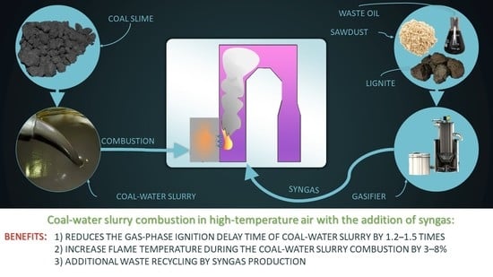
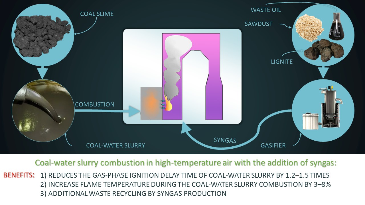
33]. At the same time, one of the main problems of the practical application of slurry fuels is the relatively long ignition delay times, which leads to mechanical and chemical fuel under-burning in furnaces with typical overall dimensions for coal-fired boilers. A potential solution to this problem is to organize the combustion process in a high-temperature oxidizing medium while adding biomass or waste-derived fuel gasification products. Therefore, it is reasonable to compare the characteristics of CWS combustion processes in a high-temperature oxidizer environment, both without the addition of gasification products, and with syngas generated during biomass and waste-derived fuel pyrolysis.
This work is focused on an experimental study of the possibility of using composite liquid fuels based on waste coal preparation, together with syngas obtained in the process of pyrolysis and gasification. Coal enrichment wastes have a fairly high carbon content with an average dry weight ash content of 20–40%. However, at present, they are of in low demand due to insufficient technology being developed for their disposal. The results of two studies [
17,
20] showed the use of slurry fuels was successful when they were co-burned with additional components. The purpose of our work is to experimentally study the CWS droplets ignition and combustion characteristics in a high-temperature oxidizer medium, with syngas pre-generated in a laboratory gasifier. The scientific novelty of the work lies in a comprehensive analysis of the main characteristics of the CWS droplet ignition and the combustion processes when an oxidizer is fed into the combustion chamber with the addition of syngases of various compositions, obtained during biomass and waste-derived fuels pyrolysis and gasification. The results of this study will be a contribution to solving the problem of coal-sludge utilization, and the optimization of slurry fuel combustion processes. The established characteristics will also be of practical importance, as they are the basis for the design of fuel preparation and supply systems, as well as boiler furnace designs.
2. Materials and Methods
Coal sludge from coking coal was used as the main CWS component, which is a waste from coal preparation. Coal sludge consists of coal and mineral particles of different fineness (up to 100 µm). At the processing plant, coal sludge is a waste product whose moisture content can vary over a wide range. To control the proportion of the fuel mixture components, the coal sludge was pre-dried until complete moisture evaporation in a drying box at a temperature of 105 °C for 3 h. Next, dry sludge agglomerates were ground in a Pulverisette 14 high-speed rotary mill (FRITSCH, Idar-Oberstein, Germany). To obtain a powder with a particle size of not more than 100 μm, crushed coal sludge was sieved using an ANALYSETTE 3 SPARTAN vibrating screen (FRITSCH, Idar-Oberstein, Germany). Tap water was used as the liquid component of the CWS. The components (solid and liquid) were mixed with an AIBOTE ZNCLBS-2500 magnetic stirrer (Aibote, Zhengzhou, China) at a magnetic armature rotation speed of 1500 rpm. The mixing time of a two-component slurry weighing 100 g was 10 min, the mass fraction ratio of solid and liquid components was 1:1.
Biomass and waste-derived fuels used as energy resources for syngas generation:
The results of an elemental and technical analysis of the solid fuel components is presented in
Table 1.
An experimental setup was designed to determine the ignition and combustion characteristics of CWS droplets with synthesis gases obtained from the process of biomass and waste-derived fuel pyrolysis to the oxidizer medium.
Figure 1 shows the 3D model of the experimental setup.
Waste-derived fuels and biomass were gasified in the original gasifier (1). The chamber volume was 3.5 L, the electric heater power was 4 kW. Prior to heating, the gasifier was purged with nitrogen (3) to create an inert medium. Waste-derived fuels or biomass were introduced into the gasifier (1) and preheated to 600 °C on a metal plate. The temperature inside was automatically regulated (2) according to the built-in K-type thermocouple readings (temperature range 0–1100 °C, accuracy ±3 °C, inertia no more than 3 s). The time the fuel spent in the heated gasifier was determined by the readings of a precision gas analyzer (4) in real time, characterizing the total yield of the volatile components from biomass or waste-derived fuel. In the syngas supply path to the muffle furnace (5), there was a filter (6) complete with a device for collecting condensate, designed to purify and dry the resulting syngas. A diaphragm pump (7) with a capacity of 3 L/min was used to supply syngas from the gasifier (1) to the muffle furnace (8).
During preliminary experiments, the generated syngas’ composition was analyzed. Sampling was carried out at the gasifier outlet (1). To register the component composition of the gas obtained during pyrolysis, a laboratory gas analyzer (4) Test-1 (Boner-VT, Novosibirsk, Russia) was used. This gas analyzer was equipped with electrochemical sensors for O2 (range 0–25%, absolute error ± 0.2%), CO (range 0–40,000 ppm, relative error ± 5%), SO2 (range 0–1000 ppm, relative error ± 5%), NO (range 0–2000 ppm, relative error ± 5%), NO2 (range 0–500 ppm, relative error ± 7%), H2S (range 0–500 ppm, relative error ± 5%), HCl (range 0–2000 ppm, relative error ± 5%). Additionally, the gas analyzer was equipped with optical sensors for CO2 (range 0–30%, reduced error ± 2%), CH4 (range 0–30%, reduced error ± 5%), CO (range 0–30%, reduced error ± 5%) and a polarographic sensor for H2 (range 0–5%, absolute error ± 5%). The gas analyzer included a modular probe, a condensate collector and a filtration system, the design of which was similar to the design of the path for supplying the resulting syngas from the gasifier (1) to the muffle furnace. The gas analyzer was connected to a PC (9) with software which allowed real-time monitoring of changes in the resulting syngas components’ concentrations.
Slurry fuel droplets were burned in a Nabertherm R 50/250/13 tubular muffle furnace (8) (Nabertherm GmbH, Lilienthal, Germany) preheated to a given temperature and used as a model combustion chamber. A droplets group was placed on a holder (10). Nichrome wire 250 µm thick was used as a suspension device. In works [
34,
35], the influence of a similar holder on the heating characteristics of fuel samples was studied. It was established that the holder made of nichrome wire does not significantly affect the heating of the fuel. To assess the scale of the influence of the suspension device on the CWS droplets’ combustion, it is worth citing the following fact. The difference between the ignition delay times of drops of identical fuels was less than 10% whether the drop was located on the holder, or when the drop moved in the heated air flow at a speed identical to the flow velocity; i.e., the relative speed was zero. The total fuel mass was about 0.2 g, and the diameter of each droplet was about 2 mm (
Figure 1). The initial droplet masses were controlled using a ViBRA HT 84RCE balance (accuracy class I, resolution 10
−4 g, with the smallest weight limit being 0.01 g) (Vibra, Japan). The holder with the fuel droplets was introduced into the combustion chamber with a linear movement device (11). The syngas was supplied to the area (
Figure 1) where the CWS droplets were located using a ceramic tube (13). The syngas flow rate supplied with the diaphragm pump (7) was 3 L/min. Thus, the conditions of the laboratory experiment corresponded to the conditions of the CWS flaring process in the combustion chamber, with a partial replacement of the air with syngas.
To record the ignition and combustion processes of CWS droplets in a muffle furnace, a high-speed video camera (14) Phantom V411 (Vision Research, Wayne, NJ, USA) was used; video recording speed was 2000 fps at a resolution of 800 × 600 pixels; color depth was 12 bit; pixel size was 20 µm; minimum exposure time was 1 µs; and an automatic image trigger was used. The AF 105 mm lens (Sigma, Tokyo, Japan) was used with the video camera; the minimum focusing distance was 0.312 m, with a viewing angle of 23.30°. Standard video camera software (Phantom Camera Control 2.6) and original software developed in Mathematica 12.3 were used to analyze video recordings.
The main recorded characteristics of the CWS droplet combustion process were the following: gas-phase (td1) and heterogeneous (td2) ignition delay times, burning duration (tb), flame temperature (Tb) and concentrations of anthropogenic emissions. In addition, analysis of the ash component composition obtained after the CWS droplet were burned was carried out according to the ASTM D3682-13 method.
In this work, the gas-phase ignition delay time is the time from the beginning of the fuel droplet heating to the gas mixture ignition in the fuel droplet vicinity. The heterogeneous ignition delay time is the time from the start of the CWS droplet heating to the moment of the coke residue ignited. Burn duration was the time from the moment of CWS droplet gas-phase ignition to the completion of the carbonaceous residue heterogeneous combustion.
To determine the flame temperature during the combustion of slurry fuels, the method of two-color pyrometry was used. The fuel combustion process was recorded using a pre-calibrated high-speed video camera complete with a lens (14). Calibration consisted of establishing the correlation between the intensity of the detected radiation at different wavelengths with the characteristics of the video camera matrix RGB channels.
In the video recording area, a fragment was selected (
Figure 2) corresponding to the flame in the vicinity of the CWS droplet. Further, within the framework of a developed Wolfram Mathematica algorithm (Wolfram Research, Champaign, IL, USA), the color image of the video recording was averaged with a given step to suppress optical noise. According to the ratio of the intensities of the green and red color channels in each pixel of the considered image fragment, the temperature was calculated according to the original algorithm using the Planck formula [
36]. The set of temperature values in each pixel of the video recording area represented the temperature field. The systematic error of non-contact temperature measurement (characterized by the ratio of the intensities of the green and red color channels) did not exceed 25% of the recorded value.
All recorded characteristics had systematic errors. Their values corresponded to the metrological characteristics of the registration means used. To estimate random errors, a series of 5–10 experiments were carried out under identical initial conditions. The contribution of uncontrolled factors to the resulting values of the characteristics being determined was evaluated by calculating confidence intervals. To process the results, including the identification and elimination of gross errors, standard approaches [
37,
38], were used, including the calculation of the mathematical expectation (1), the variance of a random variable (2), and the standard deviation (3) for each series of experiments, followed by the calculation of the confidence interval (4) [
37].
where
MX—mathematical expectation;
Xi—measurement result;
n—number of measurements;
V—random variable variance; σ—standard deviation; Δ—confidence interval;
tαn—Student’s
t-distribution.
When choosing tαn, the confidence level was set to 0.95. Further, for all the results obtained in the figures, values of the confidence intervals will be presented which illustrate the range of possible values for the measured characteristic with a probability of 95%.
3. Results and Discussion
3.1. Syngas Composition
Figure 3 shows the combustible components’ content in the composition of the resulting syngas with identical initial gasified fuels masses. The highest combustion heat was characterized by syngas obtained from sawdust pyrolysis. The reason for this is the high content of hydrogen in its composition, the combustion heat of which (140 MJ/kg) is much higher than that of CH
4 (50 MJ/kg) and CO (13 MJ/kg). In addition, syngas obtained from sawdust is characterized by the highest content of CO. The joint formation of free radicals of hydrogen and carbon monoxide proceeded in the presence of H
2O molecules [
39]:
The presence of water vapor molecules in the gasifier reactor is due to the release of hydrated and pyrogenetic moisture during the solid fuel thermal decomposition. During the sawdust gasification, a greater amount of water vapor was released, compared to other pyrolyzable fuels, due to the oxygen functional group’s higher content (phenols, alcohols, acids) in wood [
40].
In the case of fuels with used turbine oil, the main component of the syngas is methane (
Figure 3). Its formation mainly occurs during the decomposition of fatty acids into alkanes, the main component of which is CH
4. The methane synthesis occurs in the following reactions in the presence of free hydrogen radicals [
41,
42]:
The intensive formation of hydrocarbons during the thermal decomposition of used oils is a consequence of the high content of aliphatic compounds in their composition [
43,
44]. In the case of sawdust, the decomposition of methoxy groups (–OCH
3) and the breakdown of side chains of glycosidic compounds (methyl (–CH
3) or methylene groups (–CH
3–)), which originate from hemicellulose and biomass lignin, are also accompanied by the CH
4 formation [
45].
Table 2 shows the combustible components content in the syngas composition obtained under various process conditions in the gasifier. When determining the weight of pyrolyzed fuel samples, the normalization was carried out relative to the initial weight of the sawdust sample. In experiments with identical initial masses of pyrolyzable fuels, the sample weights were 5 g. In experiments with identical pyrolyzable fuels (in the initial states) combustion heats, the initial samples weights were as follows: 100% sawdust—5 g; 70% lignite + 30% WTO—3.06 g; 40% sawdust + 40% lignite + 20% WTO—3.56 g. In experiments with an identical volatiles content in a sample of pyrolyzable fuels, their masses were as follows: 100% sawdust—5 g; 70% lignite + 30% WTO—6.61 g; 40% sawdust + 40% lignite + 20% WTO—5.78 g.
The obtained results (
Table 2) indicated a relatively low content of combustible components in the syngas composition. First of all, this is due to the low mass of gasified fuel, as well as the overall dimensions and working pressure of the gasifier. In citation [
46], the syngas production with a combustible gas concentration of no more than 20% took place in a fixed-bed gasifier. The maximum concentrations of CO and H
2 did not exceed 15%, and the concentration of CH
4 did not exceed 5%, while the overall dimensions of the installation exceeded the laboratory gasifier we used by more than 20 times, and the mass of fuel loaded into the gasifier was 40–55 kg.
Based on the analysis of data on the composition of the synthesized gases (
Table 2), it can be concluded that the most promising gas, in terms of CWS ignition intensification, is syngas obtained using sawdust because it had the largest proportion of hydrogen in its composition, which ignites at a lower temperature compared to other syngas components. In addition, when using sawdust, the overall yield of syngas is also higher than other fuels, which was associated with a high proportion of bio-oil and char formation during the pyrolysis of fuels based on lignite. Thus, the share of combustible components in the sawdust syngas from sawdust pyrolysis is 3.46%, while in the pyrolysis of fuels based on lignite, this indicator is 0.83–3.44%.
The synthesis gases obtained in the laboratory gasifier were later used as additives to the oxidizing medium in ignition and combustion experiments on the CWS droplets.
3.2. CWS Droplet Ignition and Combustion Characteristics in an Oxidizing Medium with the Syngas
During experiments on the experimental setup (
Figure 1), the following characteristics were recorded: delay times for gas-phase and heterogeneous ignition of CWS droplets, combustion process duration, flame temperature.
Figure 4 shows the dependence on ignition delay times and CWS droplet burning times on the temperature of the combustion chamber when synthesis gases are supplied to the combustion area (
Table 2), obtained under different conditions. An increase in the temperature in the combustion chamber contributed to the intensification of the heating of the CWS droplets, the moisture evaporation, and the coke residue ignition. The minimum ignition delay times in all experiments were recorded for the syngas supply obtained during the sawdust pyrolysis (synthesis gases No. 1.1, 2.1 and 3.1). The high content of hydrogen in its composition, being the most reactive component, contributed to the ignition intensification.
The addition of syngas to the oxidizer medium during the CWS droplet combustion primarily contributed to the intensification of the gas-phase ignition in their vicinity. At an initial temperature in the combustion chamber of 650 °C and the addition of syngas, the delay times for gas-phase ignition are 12.5–17.5 s, which is 1.2–1.5 times (about 22 s) shorter than the CWS droplet combustion without syngas in the combustion chamber. Additional heat supplied to a fuel droplet from the combustion area led to an increase in its heating rate, moisture evaporation and volatile gas release. Collectively, these processes intensified heterogeneous ignition and carbon-residue burnout. The heterogeneous ignition delay times decreased by a factor of 1.3–2, and the burn-up duration of a fuel droplet decreased by a factor of 1.3–1.8 (depending on the syngas composition) under otherwise identical conditions. The most pronounced effect of adding syngas is seen in
Figure 4c, where the main condition of the experiment is the constancy of the volatiles content in the pyrolyzed fuel samples. When CWS is burned without syngas, the delay times for heterogeneous ignition and combustion duration vary between 16.8–21.1 s and 117.3–146.8 s, respectively. In turn, the addition of syngas to the oxidizer medium made it possible to reduce the variation ranges of heterogeneous ignition delays and burnup durations to 6.3–13.4 s and 72.1–102.6 s, respectively.
The shortest CWS droplet burning times were recorded when using syngas obtained through sawdust pyrolysis, when the volatiles content in samples of the pyrolyzed fuel was identical—about 85 s at a combustion chamber temperature of 650 °C, and about 72.1 s at a temperature of 850 °C. The reason for this is the hydrogen oxidation, which dominated the composition of the corresponding syngas, contributed to the greatest local temperature rise in the combustion zone, and, as a result, the most intense fuel burnout. During CWS combustion with the addition of syngas No. 2.2, a longer (by 2–8%) duration of fuel combustion was recorded, compared with mono-combustion of CWS. The reason for this was the very low content of combustible components in syngas No. 2.2, as well as the displacement of the oxidizer from the fuel combustion zone and its replacement with non-combustible components.
During the combustion of CWS without the addition of syngas, the duration of fuel combustion remained constant at an oxidizer temperature of 750–850 °C. In this temperature range, the burning rate of CWS increased, as well as the completeness of fuel burnout increased. Thus, the duration of burning out remains approximately the same. This effect was repeatedly recorded by us in previous studies under similar conditions. So, for example, in [
47], a similar effect was recorded, and the burning time of a fuel slurry of 55% coal, and 45% water remained practically unchanged in an oxidizer temperature range of 750–850 °C. A further increase in the oxidizer temperature to 900 °C led to a decreased burn duration of, since complete burnup of the fuel sample was achieved.
In addition to the temporal characteristics of the fuel ignition and the combustion processes, the concepts of flame temperatures during the CWS droplet combustion were also important. The temperature regime in the boiler furnace, in addition to energy generation indicators, affected the slagging processes (ash residue sticking on the heat exchanger surface) and the concentration of anthropogenic emissions in flue gases. In this regard, it is expedient to analyze the effect of adding syngas to the combustion chamber on the flame temperature during the CWS droplets combustion.
3.3. Flame Temperatures during CWS Combustion in an Oxidizing Medium with the Addition of Syngas
Figure 5 shows the typical flame temperature trends obtained during the CWS droplets combustion. The temperature in the combustion chamber was 800 °C when these characteristics were recorded. It was experimentally established that the addition of syngas to the combustion chamber led to an increase in the flame temperature during gas-phase CWS combustion, and the average value was 950 °C. The average flame temperatures during the CWS droplet combustion when syngas was added were as follows: sawdust pyrolysis, 1025 °C; 70% lignite + 30% WTO pyrolysis, 1010 °C; and 40% sawdust + 40% lignite + 20% WTO pyrolysis, 975 °C. The obtained result corresponds to the component composition of the synthesis gases (
Table 2). The higher the content of combustible components in the resulting syngas, the higher the flame temperature under otherwise identical conditions.
In addition, different times were recorded for reaching the maximum combustion temperature when using different synthesis gases. When using syngas No. 1.1, the shortest time to reach the temperature maximum was recorded. The reason for this is the different component composition of synthesis gases. Syngas No. 1.1, having the highest reactivity due to the high proportion of hydrogen in its composition, contributes to a significant intensification of the CWS droplet combustion, while methane, which is the main component of syngas No. 1.2 and syngas No. 1.3, is less reactive. In turn, when using syngas No. 1.3, the longest time to reach the maximum flame temperature was recorded, since the proportions of methane and carbon monoxide, which are characterized by the lowest reactivity, are similar in its composition.
Figure 6 shows typical temperature fields for the CWS droplet combustion with and without synthesis gases obtained from sawdust pyrolysis. It can be seen (
Figure 6) that the flame size in the early stages of gas-phase combustion with syngas was much larger, and the temperatures were higher. This effect was caused by the formation of a gas-vapor shell around the fuel droplets, which, in turn, is additionally saturated with combustible components of the syngas (mainly methane), which led to an increase in the combustion temperature, as well as an increase in the combustion area.
Based on the obtained results, it can be assumed that the addition of syngas to the combustion chamber affects not only the characteristics of the CWS droplets ignition and combustion, but also affects the composition of CWS ash residue. One of the negative effects of ash composition is slagging. It is a process of intense ash sticking in a molten or softened state on the surface of the heat-exchanger tubes. The resulting ash deposits cause the deterioration of the heat transfer characteristics from the combustion zone to the coolant. In addition, rather large ash-deposit fragments periodically exfoliate from the pipes and fall into the lower part of the furnace. This can lead to the pipe system’s deformation or destruction and damage to the furnace lining, as well as creating a need for slag-removal devices. In this regard, it is advisable to study the ash composition formed during CWS combustion with and without the addition of syngas to the combustion chamber, which will allow us to assess the potential effect of this factor on the boiler furnace slagging characteristics.
3.4. Component Composition of CWS Ash Residue
Table 3 presents the results of the CWS ash-residue composition analysis. Silicon and aluminum oxides are the main ash-residue components. The reason for this is the use of coal sludge containing impurities as a CWS solid component [
17]. When comparing the results obtained for two types of CWS combustion, it was found that the syngas supply to the combustion chamber affects the ash residue composition. The difference is in the SO
3/(CaO + MgO) ratio, which is found to be linear with SO
2 emissions in the flue gas. So, for the fuel combustion process without the syngas supply, this ratio is 0.29, and with the syngas supply—0.32. The higher this ratio, the lower the content of sulfur oxides in the flue gases composition [
17]. This effect is caused by a synergistic effect between calcium oxides, magnesium, and sulfur, which contributes to the precipitation of the latter in the ash residue [
48,
49]:
An increase in the temperature in the combustion zone during the syngas supply contributed to an increase in the intensity of these reactions, which led to a greater proportion of the sulfur oxides being bound in sulfate form [
50].
Based on the results obtained, proposals were formulated for their practical application in the framework of CWS combustion technology in an oxidizer medium with the syngas addition.
4. Practical Application
One of the most promising areas of practical application of the obtained results is the modernization of coal-fired boilers. A combined supply of air and syngas to the boiler furnace could improve the efficiency of CWS ignition. In turn, this would make it possible to utilize the accumulated volumes of various waste types, as well as increase the fuel combustion efficiency. We proposed the use of the scheme shown in
Figure 7 as part of the development of measures to prepare to transfer the boiler to a system with a syngas supply to the furnace.
For example, the CWS combustion based on low-grade coals or combustible waste can be implemented using a hot water boiler with a capacity of 0.4 Gcal/h. Preparation of the fuel composition is carried out in several stages. In the first stage, coal is crushed using a ball-and-drum mill to a particle size of no more than 100–120 µm. Then the coal enters the mixing tank, into which the required amount of water and other components (if necessary) are also added, based on the mass fractions their fuel composition. After that, the finished fuel is sprayed into the boiler furnace using a pneumatic nozzle.
The main task of the gasification unit is to convert waste-derived fuels or biomass into syngas through a thermochemical reaction and supply the resulting gas mixture, together with air, to the boiler furnace. Fuel preparation for gasification consists of two stages. At the first stage, the solid part of the gasified fuel is crushed in a mill to a size of about 140 µm. At the second stage, the solid and liquid parts of the fuel intended for gasification are mixed in the mixing chamber. The resulting fuel mixture is pumped to the gasifier, where the fuel is converted into a gaseous state. Before the syngas enters the boiler furnace, it undergoes a multi-stage purification. The heat of the high-temperature syngas is removed by means of a waste heat boiler (WHB). The cooled syngas is then cleaned in a cyclone and spray scrubber (gas conditioning) and the tar is separated. Before the syngas is supplied to the boiler furnace, sulfur components must be removed from it. The separated sulfur compounds (mainly H2S and COS) are sent to the sulfur collection setup. After that, the prepared syngas is fed into the boiler furnace together with the CWS to intensify the slurry fuel ignition. In addition, syngas, instead of natural gas or fuel oil, can be used to illuminate the flame when kindling or reducing the boiler load.
The practical application of the proposed approach will make it possible to achieve a high level of waste utilization by using the waste as the main and auxiliary fuel for slurry fuel and syngas co-combustion. Also, this scheme will allow us to achieve a reduction in the concentration of anthropogenic gaseous emissions during the boiler’s operation, in addition to improving the energy performance. Due to the gasification unit versatility, in addition to fuel based on biomass, low-grade coals and waste from the oil industry, almost any combustible waste can be used, depending on the regional and industrial factors.
In the course of our work, limitations of the study were identified. These included the small volume of the combustion chamber (muffle furnace) and gasifier. Therefore, one of the directions for further work will be the design of a combustion chamber that allows the use of CWS injection devices, as well as the creation of a gasifier with a larger volume and productivity. Another direction for further study will be an expansion of the raw material base for the creation of slurry fuel, as well as the expansion of the range of gasified waste.


