1. Introduction
The issue of energy efficiency is one of the most significant concerns in fan turbomachinery. Over decades, various efforts have been made to develop and enhance fan performance. Along this path, fans have been classified into three categories: axial, centrifugal, and Cross-Flow Fans. Compared to the other two, considerable progress has been achieved in the development of Cross-Flow Fans (hereafter referred to as CFFs).
CFFs, alternately referred to as tangential or transverse fans, represent a unique variant within the centrifugal fan family. Their distinctive design incorporates an eccentric vortex and a rotor that resembles a drum, featuring forward-curved blades [
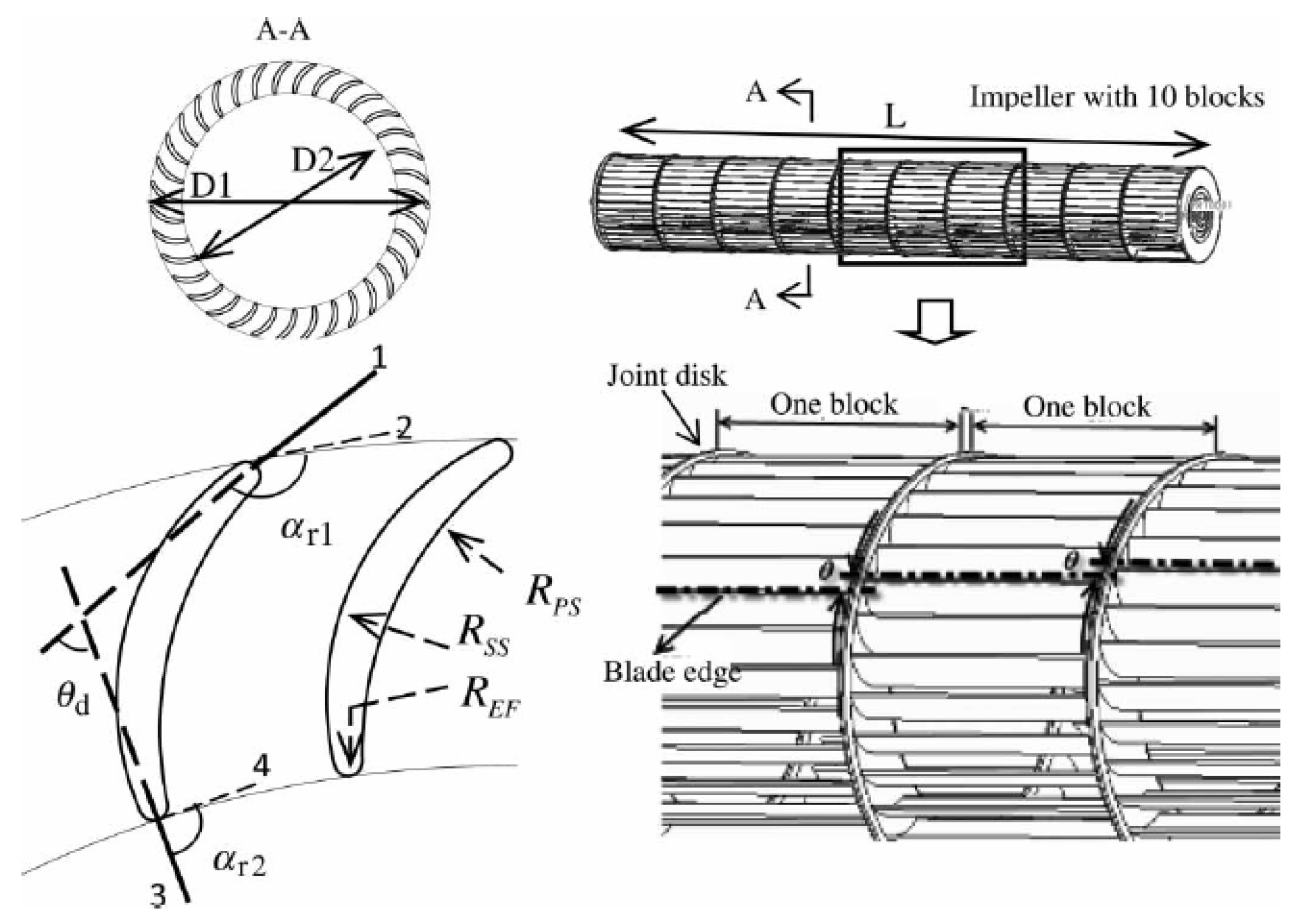
1]. The concept of a CFF was originally patented back in 1893 by an inventor named Mortier. These fans are characterized by their arrangement of numerous long blades that form a circular pattern, positioned at a specific radius from the fan’s longitudinal axis. The geometric layout and structure of a CFF are visually represented in the schematic diagram provided in
Figure 1.
To date, a substantial number of fan-based patents have been registered, and a closer examination, including a concise overview of the most significant patents depicted in
Figure 2, reveals the expanding applications of Cross-Flow Fans (CFFs) across various industries. CFFs are particularly noteworthy for their quiet operation, rendering them an ideal choice for domestic purposes and for incorporation into air conditioning systems, as noted in the study by Kim et al. [
2]. The unique characteristics of the CFF’s impeller, coupled with its high external-to-internal diameter ratio, render it exceptionally well suited for implementation in combine harvesters, as highlighted in the research conducted by Gebrehiwot and Ölvander [
3]. This points to yet another promising application of CFFs, underscoring their versatility in various domains. Furthermore, it is worth noting that CFFs have attracted attention in the context of commercial aircraft, as demonstrated by research conducted a few years ago. This suggests their potential for improving the efficiency and performance of air circulation systems within such aircraft [
4,
5,
6,
7].
Figure 1.
A schematic representation of Cross-Flow Fan (adapted from [
8]).
Figure 1.
A schematic representation of Cross-Flow Fan (adapted from [
8]).
Examining the design of Cross-Flow Fans (CFFs, also known as tangential or transverse fans), they are characterized by an impeller with a drum-like configuration. In these fans, air enters perpendicularly to the axis of rotation [
9]. Over the years, both theoretical and experimental studies have extensively explored various design parameters and their influence on CFF performance [
10,
11,
12,
13]. However, researchers have strived to identify the most critical among these parameters [
14]. Moreover, efforts have been dedicated to enhancing CFF performance, which can be impacted by both the aerodynamic characteristics of the fan and the fan’s design. In a study dating back to 1975, Yamafuji et al. [
15] demonstrated the dependency of the eccentric vortex on the vortices shed between the impeller blades. Another work explored the relationship between blade circulation and the strength of the shed vortices by measuring the flow, revealing that the removal of vorticity was necessary to prevent flow breakdown [
16]. To validate the applicability of similarity laws, Tanaka et al. conducted studies that revealed the impact of flow viscosity on the performance curve for a specific blade Reynolds number [
13,
17]. Additionally, other researchers have highlighted the influence of vortex dimensions and shapes on the performance curve of CFFs [
2,
12]. These collective efforts shed light on the intricate interplay of design parameters, aerodynamics, and performance characteristics in the context of Cross-Flow Fans.
Building upon the introduction provided above, Cross-Flow Fans (CFFs) and their diverse applications across various industries have garnered substantial interest in recent times. Numerous research endeavors have been directed toward assessing the performance of CFFs in conjunction with various operational parameters. While several review papers have elucidated the fundamental characteristics of CFFs, there remains an unfulfilled need for a comprehensive review that encompasses both experimental investigations and numerical simulations, with a specific focus on the performance and efficiency of these fans. In essence, despite the existing body of knowledge, a comprehensive review that amalgamates empirical data and computational insights to offer a holistic perspective on CFF performance and efficiency is yet to be realized. Such a review would serve to bridge existing gaps in the understanding of these fans, shedding light on their multifaceted behavior and potential improvements in a diverse range of applications.
This paper aims to persuade readers of the implemented efforts to enhance the efficiency of CFFs in various applications. It delves into research studies that explore the various facets of CFFs through experimental and numerical means. Furthermore, it places particular emphasis on their aerodynamic characteristics and acoustic performance.
2. Fundamentals and Applications of CFFs
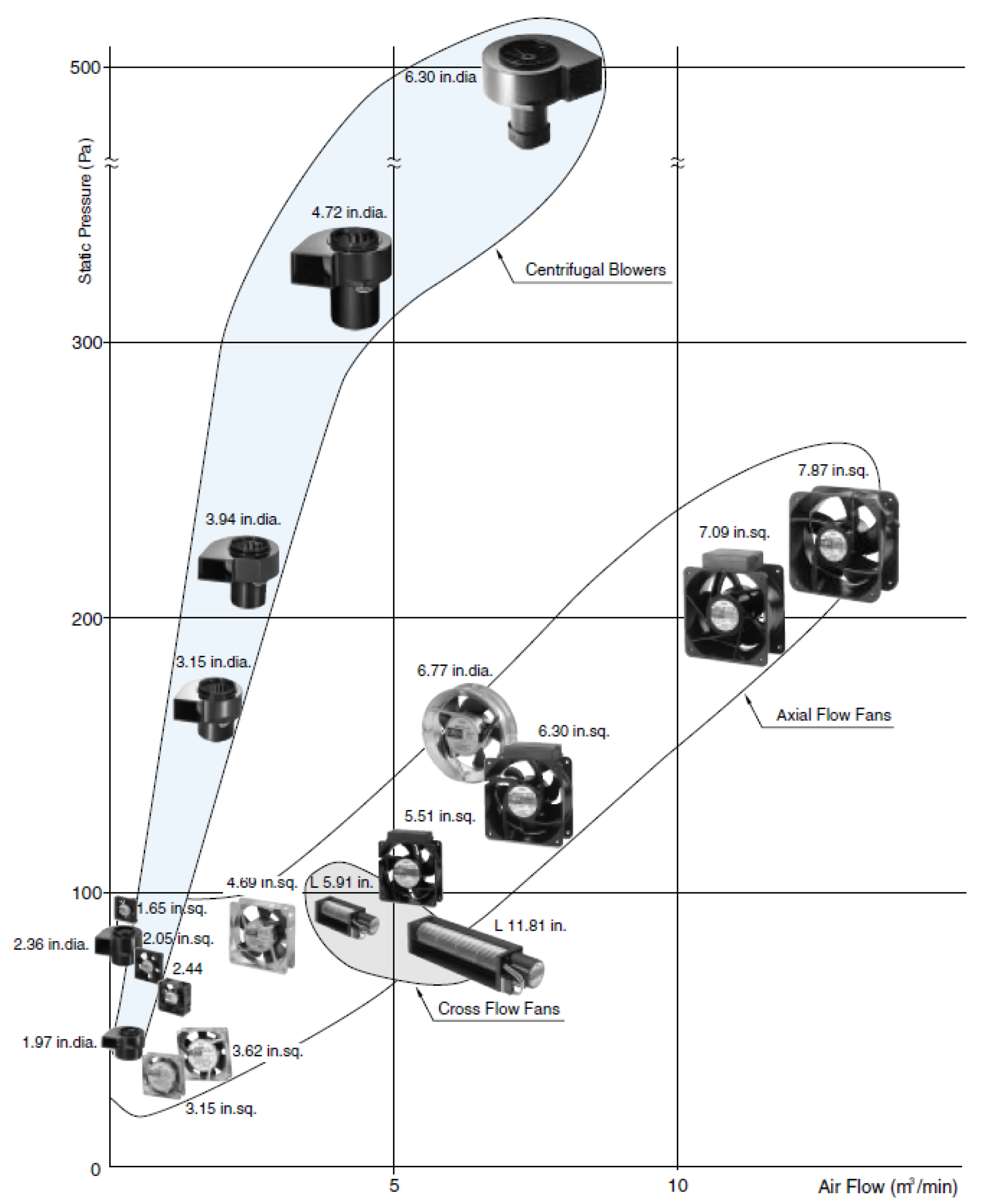
As previously mentioned, cooling fans can be categorized into three main types: axial flow, centrifugal, and Cross-Flow Fans (CFFs). When we examine these cooling fans based on their relative air volume and static pressure, as depicted in
Figure 3, a compelling perspective emerges: CFFs outperform the other fan types. This superior performance is characterized by their ability to deliver a sufficient air volume while minimizing the high-pressure losses associated with the intricate airflow pathways within a motor, which is typically designed to power the fan efficiently. In simpler terms, when assessing these cooling fans, CFFs excel by striking a balance between delivering a substantial volume of air and mitigating the high-pressure losses incurred during the air’s journey through the fan’s intricate internal mechanisms. This efficiency makes CFFs a noteworthy choice in various applications, particularly when the optimization of airflow and pressure considerations is essential.
Cross-Flow Fans (CFFs) feature a drum-type impeller with numerous forward-curved blades, capable of generating a high discharge flow rate by adjusting the impeller’s longitudinal axial length. Thanks to their cylindrical runner design, CFFs can produce a uniformly distributed airflow [
2]. The versatility of CFFs is reflected in their wide-ranging applications across various industries. For instance, CFFs have found use as window-purifying ventilators when employed as part of a mechanical ventilation system. Yamafuji et al. [
15] considering the geometric configurations, argued that understanding the fan’s characteristics is a prerequisite for optimizing ventilator performance. In the context of aircraft with propulsive wings, Dang and Bushnell [
18] reviewed the distinct flow regions of CFFs during operation and demonstrated that their efficiency is constrained by these flow regions. Eric et al. [
19] extended their work to include a novel quad-rotor CFF design for vehicles, resulting in a successful departure and landing of the proposed design. Gao et al. [
20] investigated the impact of CFFs on the performance of underwater fan-wing thrusters (UFTs), evaluating their hydrodynamic and acoustic characteristics through Computational Fluid Dynamics (CFD) simulations. They proposed a compelling set of parameters based on the obtained results. Karpuk et al. [
21] focused on implementing CFFs in short take-off and landing (STOL) aircraft, modifying the aircraft’s design parameters to enhance fan performance efficiency. As demonstrated, CFFs find a wide array of applications across industries. In each application category, specific characteristics, including design parameters and efficiency, must be carefully considered to achieve the desired performance outcomes.
CFFs have gained significant practical applicability across various industries due to their unique design and versatile airflow characteristics. One notable area where CFFs find practical use is in heating, ventilation, and air conditioning (HVAC) systems [
20,
22,
23,
24]. The compact size and ability to produce a laminar and evenly distributed airflow make CFFs suitable for applications such as air circulation in buildings, cooling electronic components, and maintaining consistent temperatures in enclosed spaces. In the field of electronics cooling, CFFs are often employed for their efficient heat dissipation capabilities. The tangential airflow produced by these fans is particularly advantageous for cooling heat-generating components, such as electronic circuitry and LED displays. The ability to direct airflow over a broad surface area without generating excessive noise makes CFFs a preferred choice in electronic devices where thermal management is crucial. Another practical application of CFFs is in refrigeration and cooling systems. Cross-Flow Fans are well suited for cooling condensers and evaporators in refrigeration units. Their compact design allows for easy integration into confined spaces, and the tangential airflow can enhance heat exchange efficiency. This application is particularly relevant in industries such as food and beverage, where maintaining optimal temperatures is essential for preserving products and ensuring product quality.
Additionally, CFFs find utility in specialized applications, such as wind tunnels. The ability to generate a controlled and uniform airflow makes Cross-Flow Fans valuable in aerodynamic testing and research. Wind tunnel experiments benefit from the predictable and consistent airflow patterns produced by CFFs, allowing researchers to simulate various environmental conditions and study the effects on aerodynamic structures. In the context of air curtain systems, commonly used in commercial and industrial settings, CFFs are employed to create a barrier of air that helps prevent the exchange of indoor and outdoor air, thus reducing energy consumption by maintaining indoor temperatures. This practical application is particularly valuable in settings such as retail spaces, where an open entrance can lead to temperature fluctuations and energy inefficiencies.
In light of the preceding explanations about the diverse applications of CFFs in different industries,
Table 1 provides a summary of this subject, including the key characteristics and results obtained from the most significant research studies conducted in the past 30 years.
Since its inception, research on Cross-Flow Fans (CFFs) has taken various approaches to understanding their inner workings. Kitagawa et al. [
9] initiated this journey with a numerical simulation using the singularity method. They meticulously analyzed the airflow within the fan, taking into account the shape of the casing and implementing a bound source modeling the blades based on Kelvin’s circulation theorem. A few years later, Shih et al. [
25] made further strides by employing the Finite Volume Method (FVM) to predict the flow field around CFFs at different rotational speeds and for various fan types. Their findings indicated a crucial relationship: the total pressure of the fan is proportional to the square of the fan’s speed. They also noted that the increase in total pressure, spanning from the entrance to the exit of the fan, correlates directly with the rotational speed.
In recent years, an array of studies has delved into the intricacies of CFF flow fields through Computational Fluid Dynamics (CFD) calculations. For instance, Wan et al. [
28] harnessed Fluent code to explore the inner flow mechanisms, revealing the internal flow characteristics of air ducts. Their findings led to numerous design options, highlighting the relatively compact nature of the reflux region. Kumlutas et al. [
30] contributed by proposing a 3D representative CFD model to evaluate fluid flow in a Split Air Conditioner. Their results were compared to those obtained from experimental tests, yielding a favorable outcome with only a 0.26% difference between the two approaches, signifying a promising alignment between computational and empirical findings. These collective efforts have significantly advanced our understanding of CFFs and their complex flow dynamics.
Regarding the performance and efficiency of CFFs, several efforts have been taken into account in different applications. By acceleration of applying them in aircraft concept, Gologan et al. [
4] have performed an analysis of the potential of CFF-based propulsive wing configuration to apply in commercial short take-off and landing (STOL) aircraft. They have tried to analyze the proposed concept’s different characteristics to evaluate the efficiency and aerodynamic characteristics of the applied CFFs. As their analysis is still in an early stage, the idea needs to be developed and thus be able to optimize as well. However, based on the obtained results, they have found that the blade design, ducts, and airfoil shape should be considered to improve the efficiency along with the aerodynamic characteristics. Sun et al. [
31] have performed the same analysis but in a different application. They have considered the influence of an eccentric vortex on the performance of a CFF of an air conditioning system both experimentally and by using CFD calculations. The output of their work proposed a new design for the inlet guide vanes, which yielded approximately a 4.6% increase in the efficiency of the fan.
More recently, Smitely [
19] has designed a quad-rotor CFF that represented a new concept for CFF-based propulsion vehicles. The calculations and experimental tests have been performed to build the proposed design to reach the required operation features (e.g. air-frame simplification, gross take-off weight reduction, and structural rigidity improvement). Similarly, Karpuk et al. [
21] have recently performed work on applying CFF in STOL aircraft. The proposed design allowed them to implement the fan as a high-lift device for a multi-purpose aircraft. Their findings indicated a high general aviation airplane is capable of utilizing the wing-embedded CFF.
In light of the research presented, the most pertinent and notable findings regarding Cross-Flow Fans (CFFs) revolve around their efficiency and optimization, as highlighted in
Table 1. Notably, one of the recent and evolving applications of CFFs involves their implementation as a ventilation system within vehicle engines, as indicated by Azzouz et al. [
34]. Although this approach remains a work in progress, the primary objective is to enhance the efficiency and aeroacoustic properties of these systems. Furthermore, CFFs have found application in the context of combined cleaning shoes, where their performance is studied through both numerical simulations and experimental methods, utilizing Computational Fluid Dynamics (CFD) calculations. CFD studies play a pivotal role in enhancing the understanding and performance optimization of CFFs. One key aspect of CFD studies in Cross-Flow Fans involves simulating and analyzing the complex flow patterns within the fan housing. CFD enables engineers to visualize the velocity distribution, pressure gradients, and turbulence levels, providing valuable insights into the aerodynamics governing the fan’s operation. By accurately modeling the geometry and boundary conditions, CFD simulations allow for a detailed examination of the airflow through the blades and the overall performance of the fan. Moreover, CFD studies contribute to the optimization of Cross-Flow Fan designs. Engineers can explore different blade profiles, variations in the number of blades, and modifications to the housing geometry to achieve the desired performance characteristics. Through parametric studies and sensitivity analyses, CFD simulations help identify the most efficient configurations, leading to improved fan efficiency, reduced noise levels, and enhanced energy efficiency. The impact of CFD studies extends beyond steady-state simulations, encompassing transient analyses that simulate the fan’s response to dynamic changes in operating conditions. This is particularly crucial in applications where the Cross-Flow Fan is subjected to varying loads or where quick adjustments in airflow are required. CFD aids in predicting the transient behavior, ensuring that the fan operates reliably under diverse conditions [
31,
35,
36].
This research delves into various aspects, including the impact of vortex walls on fan performance and the influence of rotor outlet openings on the distribution of airflow between the two outlets. These investigations collectively contribute to a deeper understanding of CFFs, exploring their potential applications, improvements, and their intricate interactions with airflow and performance parameters.
3. Correlation of Design Parameters and Performance in CFFs
Numerous research studies have primarily focused on examining the design parameters that affect the efficiency and performance of Cross-Flow Fans (CFFs). Over time, a diverse range of CFF variants has been meticulously developed and successfully applied across various industries. However, in line with the previous section, there is a noticeably increasing commitment to comprehensively evaluate the impact of different design parameters on CFF performance. This growing emphasis on scrutinizing design parameter influence underscores the increasing recognition of the importance of fine-tuning CFFs to meet the specific requirements of various applications. Such research not only contributes to the continuous improvement of CFF designs but also enables their more efficient and effective utilization in a variety of industrial and engineering contexts.
In reference to the work conducted by Lazzaretto [
14], a specific criterion has been established to define the geometric variables necessary for characterizing fan performance, both in experimental and numerical settings. This criterion serves as a fundamental guideline for evaluating and optimizing fan designs. Eck et al. [
37] employed a one-dimensional theoretical model that involved an analysis of blade cascades. Through their research, they identified specific values for
and
, representing the internal and external blade angles, respectively. Notably, they observed that reducing the external blade angle can enhance the total pressure coefficient, with a primary emphasis on the external blade angle rather than variations in the internal blade angle. However, other researchers have proposed a more comprehensive range of blade angles for optimization, considering both internal and external blades [
13,
17]. Murata et al. [
12] contributed to this understanding by emphasizing the significance of evaluating the gap between components and the setting angle, as these factors also significantly affect fan performance. Taking an overarching view of the findings from Tanaka and Matsuki’s numerical simulations [
38,
39], it becomes evident that specific blade Reynolds numbers play a pivotal role in influencing flow viscosity, while the dimensions of the impeller also have a significant impact on fan performance. These collective insights form the basis for refining and optimizing fan designs, contributing to the ongoing enhancement of fan efficiency and effectiveness.
Kim et al. [
2] embarked on a comprehensive examination of the interplay between the flow field and, by extension, the performance of Cross-Flow Fans (CFFs). To elucidate the intricate relationship between these elements and the design parameters, they embarked on a computational journey. Their approach involved solving a two-dimensional unsteady governing equation, a mathematical representation of the fluid dynamics at play, employing the Finite Volume Method (FVM). This computational method is a powerful tool for simulating fluid flow and heat transfer in complex systems. A notable aspect of their methodology was the utilization of a sliding grid system, which enables dynamic grid adjustments to capture the evolving geometry of the flow field. This flexibility in grid adaptation is particularly advantageous when dealing with rotating machinery, such as CFFs. Additionally, they incorporated the standard k-
turbulence model, a well-established model in fluid dynamics, to simulate turbulence effects in the flow field accurately. This choice allowed them to capture the intricate details of the velocity profile around the impeller. Importantly, they conducted these simulations while maintaining a constant rotating speed but varying the design parameters. This approach enabled them to systematically investigate the impact of different design choices on the velocity distribution around the impeller. By systematically exploring these variables, Kim and their team could provide valuable insights into the performance characteristics of CFFs and how they relate to design parameters. Their work contributes significantly to the understanding of CFF behavior and informs the ongoing refinement of these fans for various applications.
Ahn et al. [
2] harnessed the mean streamline analysis to forecast the performance of Cross-Flow Fans (CFFs) by employing empirical loss correlations. This analytical approach involves examining the mean flow paths of the fluid through the fan to assess its efficiency and behavior. The results obtained from this method were rigorously examined and validated, confirming the effectiveness and reliability of the proposed technique. It is important to note that while this approach does not comprehensively address the unique characteristics associated with low-flow conditions, which are specific to CFFs, it nonetheless demonstrated a commendable level of accuracy when predicting performance based on performance curves. This suggests that the predictive methodology introduced by Ahn and their team could serve as a valuable tool during the design phase of CFFs. By utilizing this approach, designers and engineers can make informed decisions about the fan’s configuration and operating conditions, ultimately leading to more effective and efficient CFF designs. This is a testament to the adaptability and applicability of this predictive approach in optimizing the performance of CFFs for various applications.
As briefly stated, Lazzaretto et al. [
14] introduced an original criterion that primarily concerns the selection of geometric variables, particularly related to the impeller geometry and shape. Although their primary focus revolved around the casing geometry, their approach provides a valuable roadmap for enhancing design and improving efficiency. This criterion, as proposed by Lazzaretto et al., serves as a guiding principle, offering a structured method for making informed decisions regarding the geometry of the impeller and its casing. It lays the groundwork for optimizing the performance of fans, particularly Cross-Flow Fans (CFFs), and enhancing their overall efficiency. Furthermore, Tanaka and Murata have made significant contributions to the field by employing Laser Doppler Velocimeter (LDV) measurements to assess the velocity field and determine static pressure distributions in CFFs. Through their work, they uncovered a distinctive scale effect within the flow dynamics. As they increased the rotor size, they observed changes in vorticity and pressure drop within the eccentric vortex. This scale effect revealed intriguing details in the flow behavior, prompting the consideration of various diffusion rates. As a result, they proposed this scale effect as an optimized approach to enhance CFF performance. Their work underscores the importance of understanding the intricate details of CFF operation and how design variables can influence efficiency and performance, ultimately contributing to the ongoing improvement of these fan systems.
Seo et al. [
26] conducted a numerical investigation to explore the impact of blade angles near the diffuser blades on the flow characteristics within a room air conditioner. Their study delved into the intricate dynamics of the air movement, particularly considering different blade discharge angles. To achieve this, they utilized Computational Fluid Dynamics (CFD) and applied a commercial software tool called Ansys Fluent. This software allowed them to perform detailed simulations of two-dimensional, steady thermal flow fields within the air conditioning system. The investigation encompassed a range of angular velocities to comprehensively assess how variations in blade angles influenced air circulation. To model turbulence in the flow, they employed the standard k-
turbulence closure model, a well-established approach for capturing turbulent flow behavior. Through their simulations, Seo and their team effectively replicated the flow patterns generated by the impeller. One of the key findings of their study was the formation of a significant vortex zone around the impeller, particularly in the vicinity of the diffuser blades. This phenomenon was attributed to the influence of the upper blade configuration. The presence of this vortex zone has important implications for the performance and efficiency of room air conditioners, highlighting the intricate relationship between blade angles and flow dynamics in these systems. Such insights are valuable for optimizing the design and operation of room air conditioners and similar equipment.
Toffolo et al. [
40] engaged in a comprehensive evaluation of the flow field within Cross-Flow Fans (CFFs) using numerical approaches. Notably, they did not stop at numerical simulations; they took their investigation a step further by validating their numerical models against experimentally recorded data. This combination of computational and experimental methods provided a robust foundation for their research. Their analysis did not merely focus on describing the flow patterns but also extended to a detailed assessment of the performance and efficiency of CFFs. To achieve this, they conducted a thorough qualitative and quantitative energy loss analysis. This in-depth exploration allowed them to identify and consider a set of critical design parameters. One of their noteworthy findings highlighted the undeniable influence of the flow rate on fan efficiency. Their research underscored that variations in flow rate have a specific and pronounced impact on the efficiency of these fans. Importantly, they emphasized that these results should be given careful consideration during the design phase of CFFs to optimize their performance and efficiency. Another group of researchers, including Lazzarotto and colleagues, delved into the impact of Reynolds number and dimensions on the similarity operation of CFFs [
41]. With a keen focus on the geometric characteristics of the casing, they strived to discern the effects of altering the rotation speed on fan performance. Through their investigations, they unveiled several significant findings related to how these features affect the performance of CFFs. Their work contributed valuable insights into the interplay between design parameters, fan geometry, and efficiency. Furthermore, the same group of researchers extended their efforts to consider fan geometry [
42]. Based on criteria such as maximum total pressure, total efficiency, and flow rate, they proposed a specific fan design. Their systematic approach to fan design, underpinned by rigorous analysis and measurements, offers a structured and data-driven method for enhancing the efficiency and performance of CFFs, furthering the understanding of these fans in different applications.
In the context of employing Cross-Flow Fans (CFFs) for Split Air Conditioners, Wu et al. [
27] conducted a comprehensive investigation that combined numerical simulations and experimental validations to assess both the aerodynamic and acoustic performance of the fan. They applied Computational Aerodynamic Acoustics (CAA) to gain a deep understanding of the intricate interplay between fluid dynamics and acoustics. Their research involved the numerical simulation of essential parameters such as flow rate and Sound Pressure Level (SPL), which were further validated through experimental testing. What sets their work apart is the consideration of various design parameters, including the vortex tongue gap, volute casing gap, and both inner and outer blade angles. These parameters were systematically studied in a parametric analysis, allowing them to draw meaningful conclusions regarding the optimization of aerodynamic and acoustic performance in Split Air Conditioners. The insights obtained through Wu et al.’s research serve as a valuable foundation for enhancing the design and operation of Split Air Conditioners, particularly when implementing CFFs. By addressing the interplay between aerodynamics and acoustics, they contribute to more efficient and quieter air conditioning systems, which is a significant advancement in the field. Additionally, Sun and their team have also delved into the effect of the eccentric vortex on CFF performance in Split Air Conditioners. Their work involved a two-dimensional Computational Fluid Dynamics (CFD) analysis, providing detailed insights into the impact of the vortex. Based on their findings, they proposed a novel design for the inlet guide vanes, a critical component of CFF operation. This design modification was particularly effective in reducing vortex shedding from the fan blades, thereby minimizing the size of the eccentric vortex. The consequence of this design change was an improvement in fan efficiency. Their experimentation yielded approximately a 5% enhancement in fan performance, showcasing the practical benefits of their innovative design proposal. This research not only advances our understanding of CFF behavior but also offers tangible improvements that can be applied in practice to create more efficient and effective split air conditioning systems.
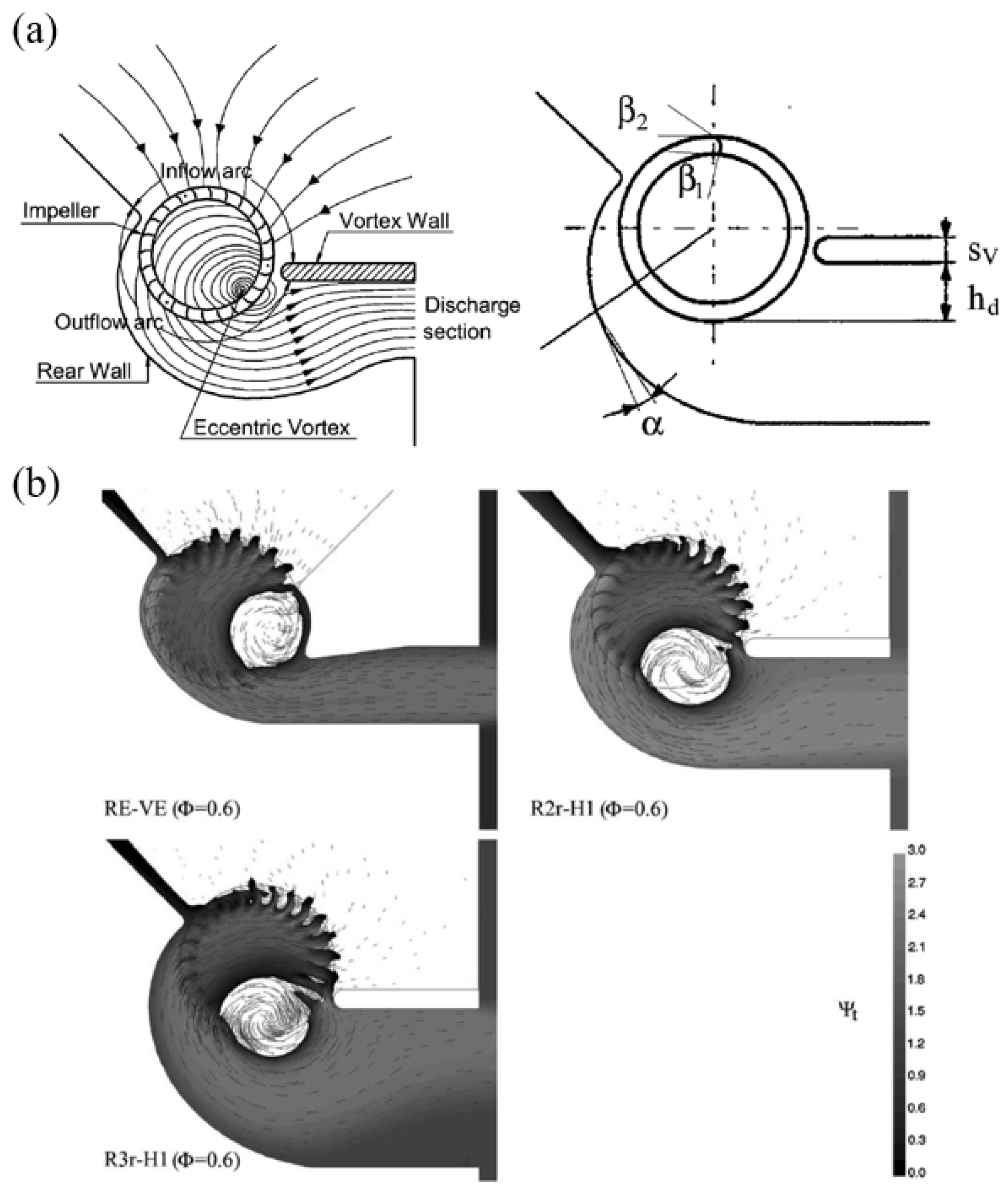
Another study has centered on establishing the correlation between design parameters and the performance of Cross-Flow Fans (CFFs) [
43]. The most critical parameters influencing the fan’s performance are depicted in
Figure 4a, while contour plots illustrating the entire pressure fields are presented in
Figure 4b. The researchers identified a relationship between these design parameters, the flow-field pattern, and fan performance. The study’s focus was primarily directed towards investigating the connection between the rear wall and the flow field, with specific attention given to the radial width of the rear wall. Nonetheless, the position and thickness of the vortex wall were also examined to establish their relationship and their impact on the flow field, and by extension, the fan’s performance. It is worth noting that the research primarily concentrated on assessing the performance of the fans by considering parameters such as the total pressure coefficient, total volumetric and hydraulic efficiency, and the maximum flow coefficient.
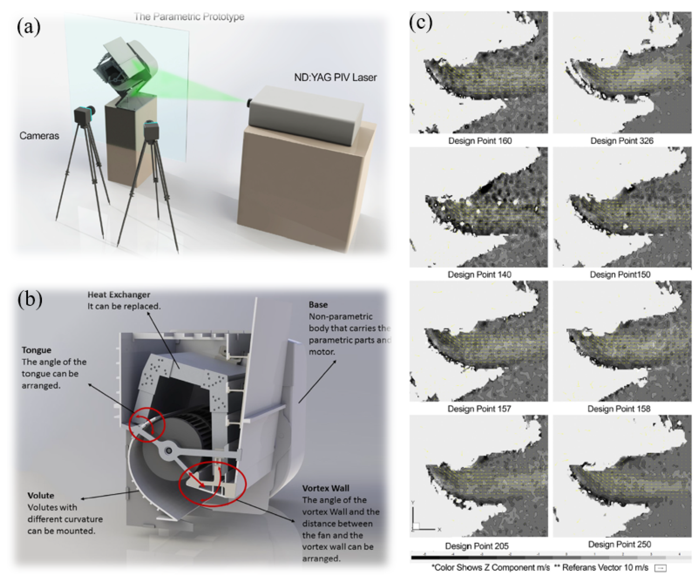
Ozer and Kumlutas [
44] conducted a study to examine the flow effects of an embedded Cross-Flow Fan (CFF) within a Split Air Conditioner (SAC). Their research involved a parametric study aimed at evaluating the impact of specific parameters on the defined objective. As illustrated in
Figure 5a, the parametric prototype consists of a base and parametric components. For a clearer perspective, the schematic diagram of all the parameters under consideration is presented in
Figure 5b, encompassing elements such as volute design, tongue angle, vortex wall angle, and vortex wall distance. To assess the impact of these design parameters on flow structures, the researchers employed Stereo Particle Image Velocimetry (SPIV). Their findings revealed the significance of each parameter. Notably, the vortex wall angle was found to have an approximate 12% effect, while the volute curvature exerted a 32% influence on the flow rate.
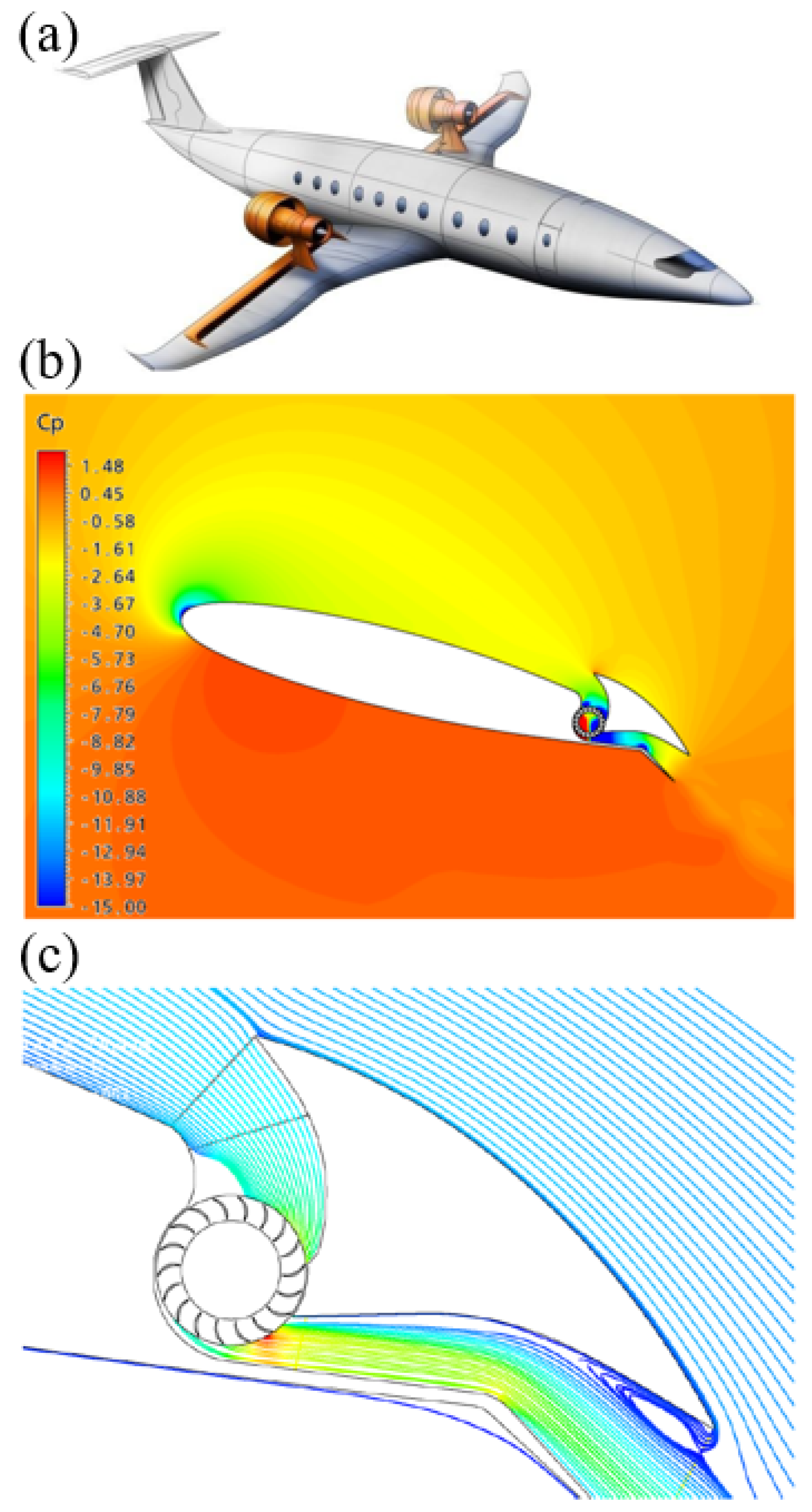
Despite the various applications of Cross-Flow Fans (CFFs), recent research has been increasingly focused on their potential implementation in Power-Lift Regional Aircraft, as exemplified by the work of Gologan and colleagues [
4]. Indeed, CFFs have shown promising potential for enhancing the lift coefficient, which is a critical factor in aircraft design. A conceptual representation of a regional aircraft featuring a CFF for a powered lift system can be seen in
Figure 6a. This design concept illustrates the idea of integrating CFFs in over-wing mounted engines.
Figure 6b visually demonstrates how this integration leads to an increase in aerodynamic lift by reducing static pressure on the upper side of the airfoil. Furthermore,
Figure 6c provides an overview of the flow field associated with the CFF, encompassing the fan intake and outlet. Notably, the maximum speed recorded was 200 m/s, indicating flow separation in the inlet duct. The observed compatibility of the inlet lip radius with the desired outcome is a noteworthy finding. The authors of this study assert that various design parameters, including fan blades, ducts, and airfoil shape, play a pivotal role in optimizing such designs. This research contributes valuable insights into the potential application of CFFs in enhancing lift coefficients for Power-Lift Regional Aircraft.
In response to the insights gleaned from the studies mentioned earlier, a cohort of dedicated researchers has undertaken the ambitious task of conducting a multi-objective optimization, with a particular focus on enhancing the performance of Cross-Flow Fans (CFFs). As we have previously explored, Toffolo and their team were acutely aware of the intricacies inherent in the flow field surrounding CFFs. Their research was intentionally oriented toward the intricate process of designing these fans, with a primary goal of delving into the intricate relationships that exist between various design parameters and the multitude of characteristics that define CFF performance. Their investigation, characterized by its depth and thoroughness, ventured into the repercussions of altering both the casing and impeller on the static pressure coefficient. This multifaceted exploration yielded a diverse array of outcomes, highlighting the inherently complex nature of CFF design and performance. It is evident from these variations that there is a pressing need for a comprehensive and systematic inquiry into the intricate and multifaceted influence of design parameters on the performance of CFFs. This quest for optimization is poised to unlock a deeper understanding of these fan systems, ultimately leading to more efficient and effective applications across various industries.
4. Aerodynamic Characteristics and Performance of CFFs
In the pursuit of enhanced energy efficiency, a pivotal criterion across diverse applications, organizations worldwide are diligently engaged in efforts to control and optimize their energy consumption. This proactive approach is geared towards augmenting the efficiency of production processes, aligning with the broader goal of sustainable energy usage. Within this landscape, scientists and researchers have embarked on an intensive exploration of Cross-Flow Fans (CFFs) through meticulous experimental and numerical analyses. Among the myriad challenges encountered by scientists delving into CFF studies, one of the focal points has been the comprehensive analysis of performance. This endeavor involves a rigorous evaluation of the aerodynamic characteristics of CFFs, encompassing intricate aspects such as flow characteristics and in situ visualization, as well as the diverse flow patterns inherent in this type of fan. To address these challenges, numerous studies have been undertaken, each contributing valuable insights into the behavior of CFFs under varying conditions. One noteworthy area of exploration has been the examination of flow characteristics concerning different parameters, a topic thoroughly investigated in seminal works such as [
45].
In what follows, flow characteristics, various regions that exist in CFFs, and the flow-field patterns will be discussed. In the subsequent discussion, we delve into an in-depth exploration of flow characteristics, dissecting the various regions within CFFs, and unraveling the intricate flow-field patterns that define their behavior. This nuanced analysis promises to shed light on the underlying mechanisms governing CFF performance, paving the way for more informed design choices and ultimately driving advancements in energy-efficient technologies.
4.1. Flow Characteristics
In CFFs, the working fluid undergoes two passes through the impeller, eliminating any distinction between inlet and exit angles. This characteristic leads to CFFs having higher dynamic pressure and greater circumferential velocity. In fact, the flow fields within CFFs exhibit various vortices, including the eccentric vortex and the free vortex.
Kim et al. [
46] involved a comprehensive assessment of the flow dynamics and performance of Cross-Flow Fans (CFFs). To delve into this analysis, they considered a range of critical design parameters, including the stabilizer position, setting angle, impeller exit angle, and rear guider shapes. A dedicated design program was developed to calculate the pertinent parameters and facilitate this investigation. Their approach encompassed both numerical simulations and experimental procedures. By comparing the results derived from their custom-designed program, they aimed to obtain a thorough understanding of CFF behavior. The numerical aspect of their analysis involved the discretization of governing equations through the Finite Volume Method (FVM), allowing them to compute solutions for flow variables. To identify an optimal geometry, Kim et al. applied the k-
turbulence model and utilized experimental apparatus. The integration of numerical and experimental data empowered them to refine the design and enhance the performance of CFFs, a valuable contribution to the field of fan technology.
Funaki et al. [
47] focused on investigating the impact of aspect ratio and Reynolds number on short-axis Cross-Flow Fans (CFFs). In contrast to the study conducted by Kim et al., the authors adopted a Particle Image Velocimetry (PIV) technique to precisely measure flow velocities within the CFF. Notably, their experimental setup did not incorporate casings, and their examination centered on two distinct impeller types: forward-chambered blades and radial-flat blades. A significant outcome of their study was the ability to categorize the generated flow into three distinct modes. As a result of this classification, Funaki et al. created flow-regime maps specifically tailored to the impellers they employed. One of the most noteworthy aspects of their research pertained to the definition of an outflow rate from the impeller, which they derived from the PIV results. Their conclusion was particularly intriguing, as it revealed that the outflow rate coefficient remained independent of both the Reynolds number and aspect ratio. This finding holds particular relevance for the understanding and design of short-axis CFFs, offering valuable insights into their operational characteristics.
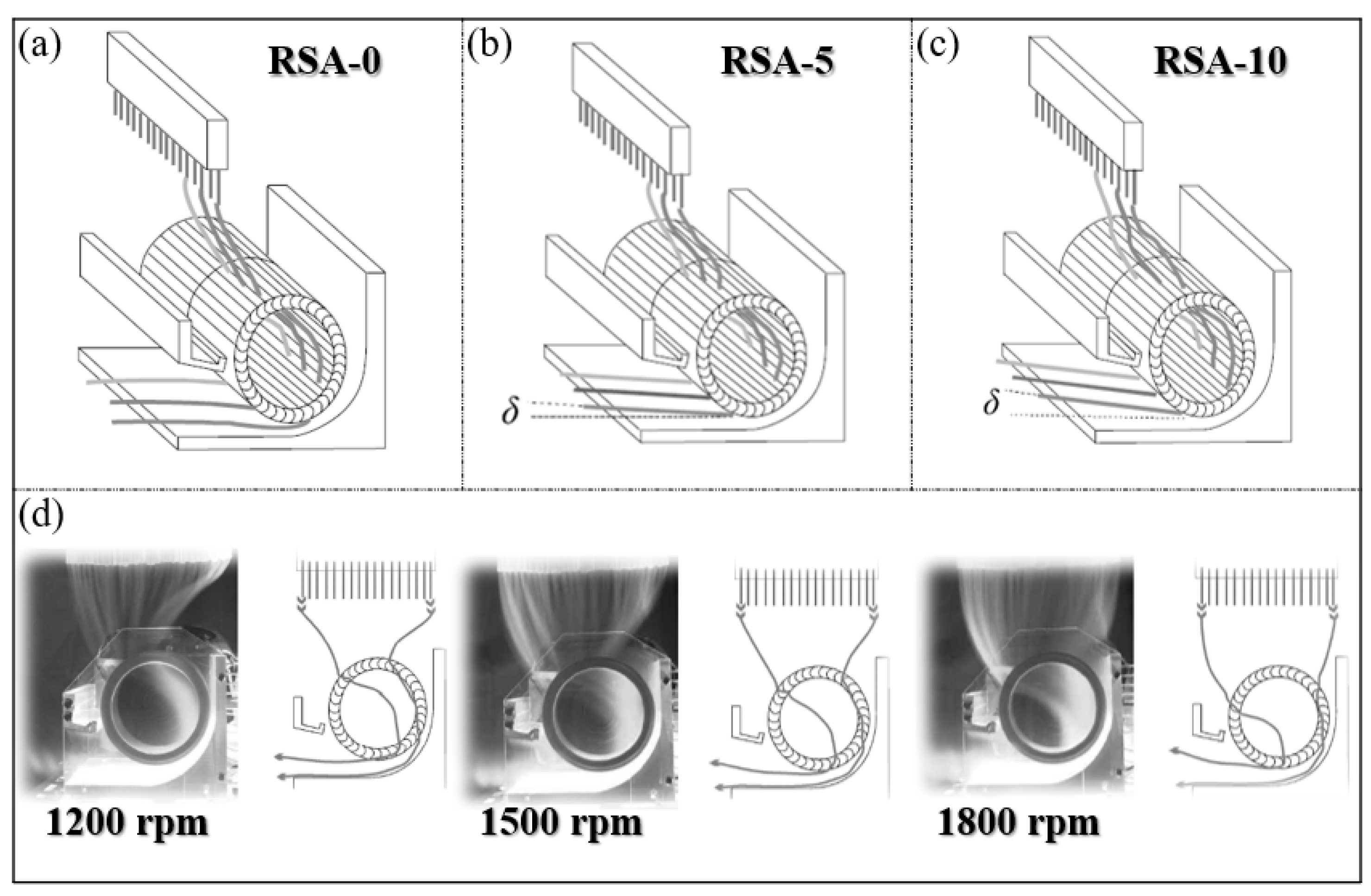
Tsai et al. [
48] analyzed the flow patterns of CFF with three different rotor-screw angles (RSA). Their observation methods and findings are summarized in
Figure 7, which includes (a–c) the visualization of the 3D axial flow patterns and (d) cross-sectional observations at different speeds for RSA-0. Based on the results obtained from their proposed flow visualization setup, it is evident that each angle has a distinct impact on the pressure levels and noise generation.
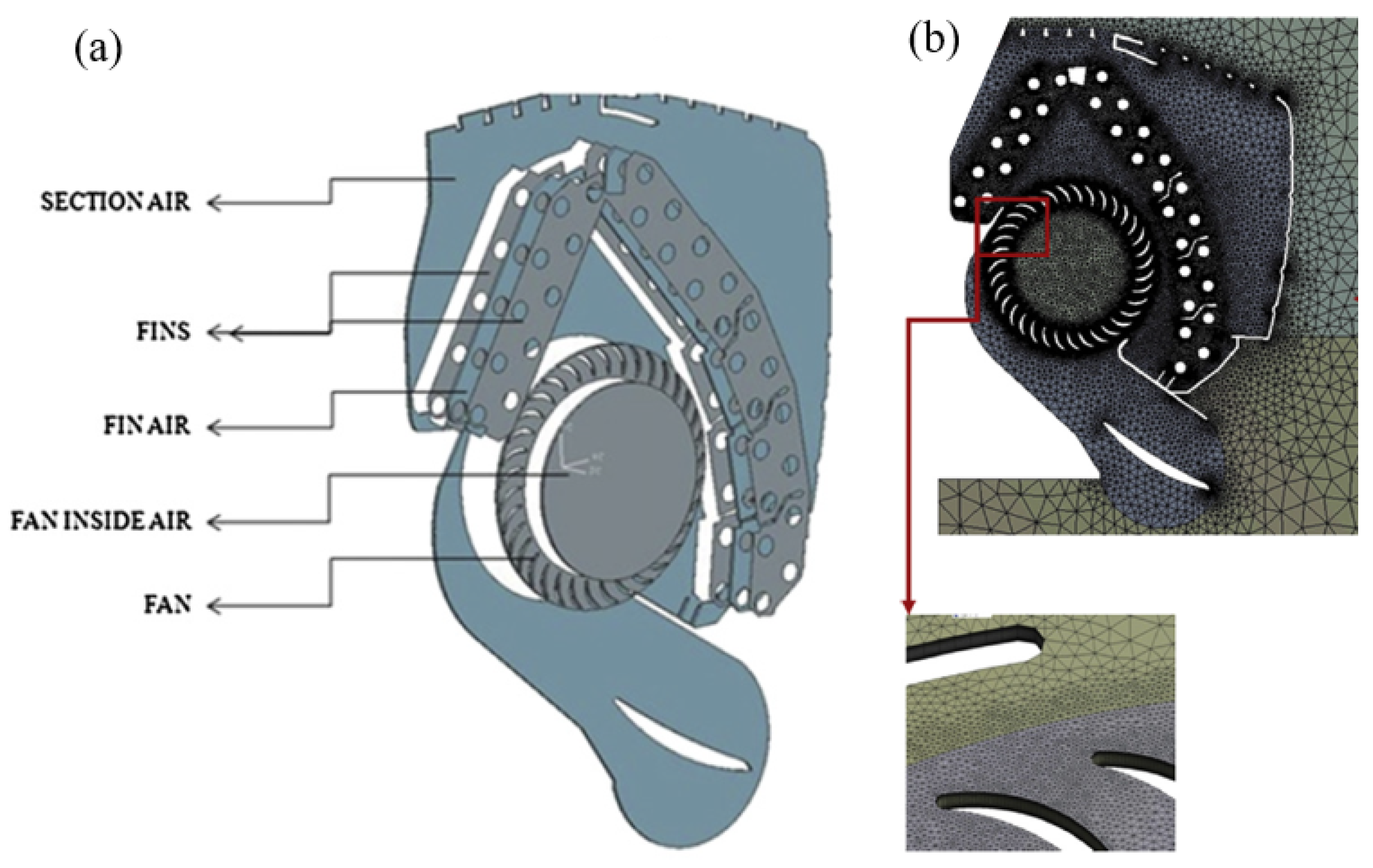
In addition to the various applications of CFFs, other research endeavors have sought to assess the aerodynamic and aeroacoustic characteristics of these fans. Kumlutas et al. [
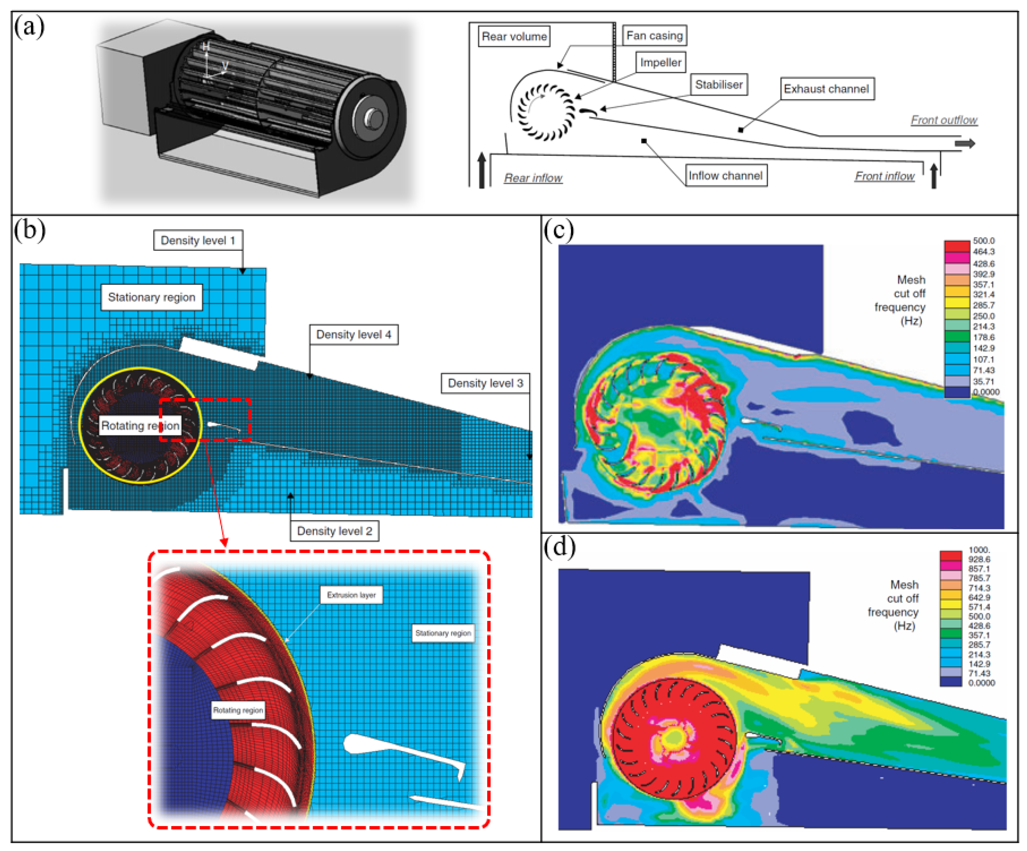
30] delved into both the fluid dynamics and heat transfer aspects of a Split Air Conditioner (SAC) while considering the integration of a CFF within this specific application. They placed particular emphasis on comprehending the intricate flow patterns that manifest within CFFs, and, as a result, they introduced a comprehensive 3D model to analyze the airflow and heat transfer within the SAC unit. To be more precise, they proposed a thin-section model for simulating the indoor unit of the SAC. It is worth noting that this innovative approach serves as a general framework, which is ultimately destined for application in a real-world scenario to verify its validity. Consequently, they conducted experimental tests to validate their proposed model. Furthermore, they sought to validate their model through experimental procedures involving heat transfer measurements and Stereo Particle Image Velocimetry (SPIV). Given that the internal structure of the SAC unit includes the CFF, rear wall, and vortex wall, the airflow within the unit was modeled using a 2D approach, employing nodes for implementing the Finite Volume Method (FVM). The 3D numerical model of the SAC indoor unit, along with mesh details, is presented in
Figure 8.
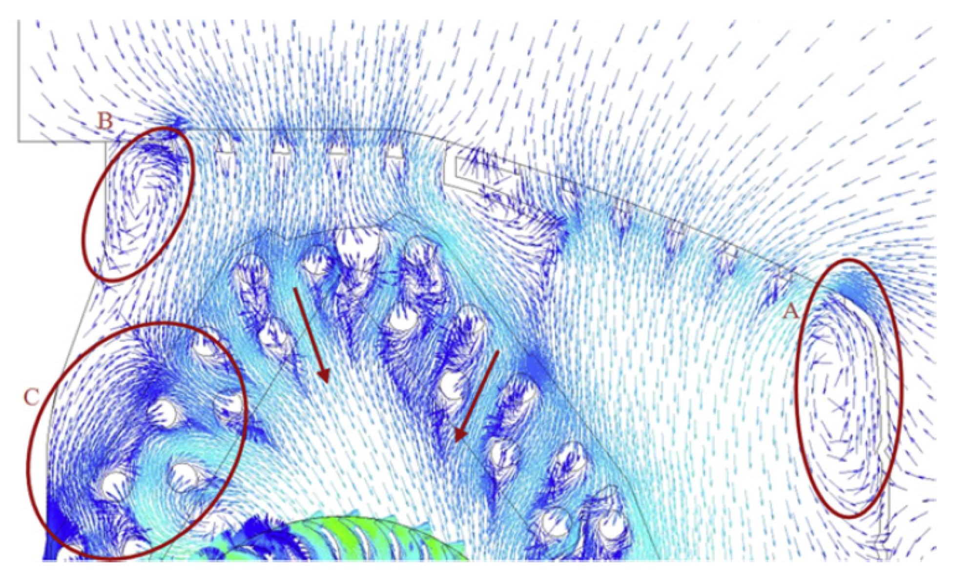
In the numerical analysis of fluid flow, after implementing the boundary conditions and setting the specified velocity at 1200 rpm, the flow conditions were visualized using streamlines (refer to
Figure 9). As shown, the airflow originates from the upper exterior region and moves towards the suction holes. This results in the formation of a jet flow, driven by the substantial pressure differential between the conditioned and ambient air.
Overall, it has been shown that there is a good agreement between the numerical and experimental approaches. Consequently, the thin-section model is an acceptable assumption through evaluating the CFFs’ performance. A capacity difference of 0.26% between the test room data and the developed model was obtained, as mentioned by the authors.
The influence of various design parameters such as impeller exit angles, stabilizer position, and setting angle on the performance and flow characteristic of CFF has been investigated using a numerical approach [
46]. The standard k-
turbulence model has been applied to simulate the turbulence behavior. Considering the experimental validation of the proposed approach, an optimum design has been obtained following the obtained experimental and numerical results.
4.2. Flow Regions
Cross-Flow Fans (CFFs) offer distinctive advantages in various applications due to their specific design. Nevertheless, one of their most significant drawbacks is their relatively low efficiency, which is why research and efforts to enhance this type of fan are ongoing. As the utilization of CFFs varies from Split Air Conditioners to aircraft, the need for a standardized design with specific parameters becomes apparent. Therefore, it is essential to recognize the distinct characteristics of these fans in their various applications.
To acknowledge the mentioned issues, the basic aerodynamics and energy transfer processes should be taken into account. One can mention the flow and its characteristics within the impeller. In fact, the flow field in a CFF is two-dimensional, which transfers from the blade row, passes within the interior of the impeller, and then passes radially through the blade row. The most important feature is that the characterization of flow can take place by the construction of the eccentric vortex placed parallel to the rotor axis. Accordingly, researchers have tried to perform experimental work on this part [
11]. It has been shown that even with the casing wall, the mentioned eccentric vortex would still exist. To realize more specifically the flow’s characteristics, other works have been developed numerically. Bushnell et al. have assumed the flow of a fan could be divided into three zones. The most important feature of this approach is that the flow region boundaries rely on the prediction of the flow, which itself is influenced by the design parameters based on the findings of other related works [
49,
50,
51].
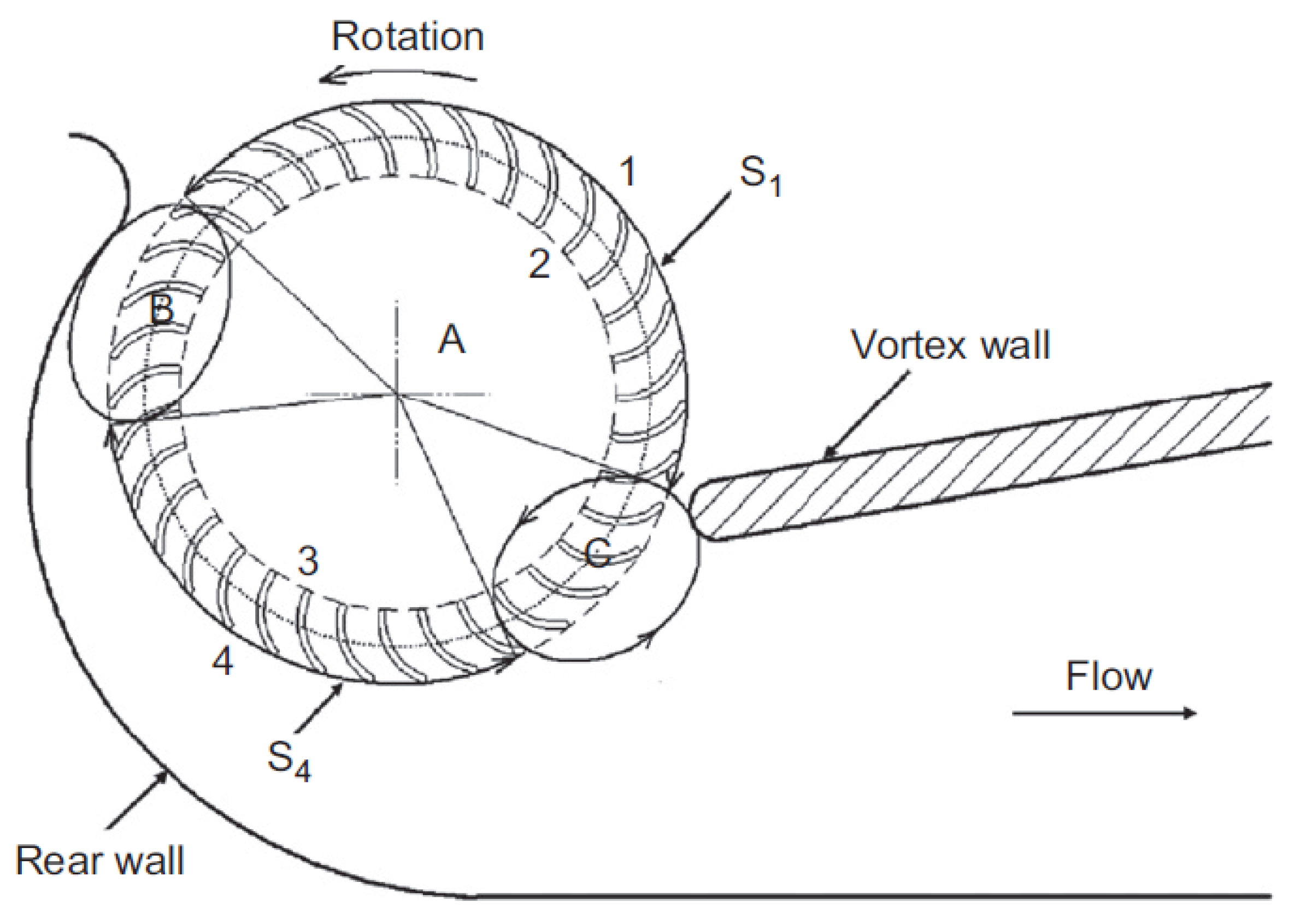
There are three flow regions in CFFs, as mentioned previously. These regions are schematically illustrated in
Figure 10. Dang and Bushnell [
18] have comprehensively discussed these flow regions. They are named A, B, and C. Region A corresponds to the inlet flow and includes most of the air that enters the fan. The flow in region A consists of two stages: flow passage through the suction arc blading and flow passage through the discharge arc. In this zone, the effect of the vortex could be included along with the two stages augmenting the pressure coefficient. Region B refers to the zone that is the important part of the flow passage in CFFs, and its role is not effective on the fan’s performance. Region C is exactly the eccentric vortex. The most important feature of this zone is that there is a re-circulating of flow, and, thus, there might be energy dissipation that affects region A.
From the above-mentioned explanations, it seems that regions B and C do not play an important role in the flow characterization of CFFs. However, their role is inevitable and should be considered for the flow field evaluation accordingly.
Dang and Bushnell have characterized the energy transfer and flow characterization in regions A, B, and C. As the most critical region in CFFs refers to the flow in region A, it is important first to consider this issue and then apply the findings as the boundary conditions for regions B and C. They have considered the velocity diagram to correlate them to the first and second stages for further investigations. Efforts have been taken into consideration to obtain the pressure coefficient as an important criterion in the performance analysis of CFFs.
4.3. Flow-Field Pattern
In 1891, the structure of the flow field was patented. After a few years, several visualization studies were performed through an eccentric vortex within the impeller, and it was found that the vortex is capable of acting as an aerodynamic seal for controlling the re-circulation of flow from discharge. In the work of Eck et al., they proposed a small rear wall along with a thick vortex wall, taking into account a decrease in the value of the radial clearance in the rotation direction. Another work has considered the pressure coefficient as an important criterion representing the role of the vortex on the flow-field pattern [
11].
In addition to the described works, several efforts have been taken into account to develop numerical approaches regarding the prediction of fan performance. The most important works are summarized as follows:
Combined solution of a forced vortex flow [
52].
Simple potential flow with a single vorticity source [
37,
53].
Potential flow resulting from a couple of equal vorticity sources [
54].
Accordingly, there are other studies that have worked on the flow field experimentally. Murata and Nishihara have worked on the flow field and its relation with the characteristic curve by which the casing shapes have been thoroughly investigated [
12]. They have considered the different casing shapes to evaluate their effect on the flow field in various geometric parameters. Furthermore, several impeller blade profiles, such as radial and circular, have been tested, and the author showed that the eccentric vortex varies for different profiles [
15].
Based on the geometry of the designed CFFs and also the operating conditions, there might be secondary vortices in the inlet and outlet zones. As shown in
Figure 11, CFFs consist of a broad cylindrical rotor by which air passage takes place through the blade two times. In fact, the airflow controlled by a large vortex on both the inside and outside of the impeller is a function of the vortex’s size and intensity that is affected by the geometrical parameters of the casing as well as the operation point [
55,
56].
Due to the complexity of the airflow and its structure, it is crucial to perform several experimental tests. On the other hand, as the design techniques are not applicable in CFFs with acceptable results, implementing numerical techniques is inevitable. The objective is to simulate the complex flow in CFFs and avoid a large number of experiments in the design and development procedures. To accomplish this, Computational Fluid Dynamics (CFD) calculation is an approach for simulation of the flow field and other related characteristics of the CFFs [
57]. It is worth mentioning that experimental techniques, such as Particle Image Velocimetry (PIV), are normally used for measurement of the characteristics and performance of the CFFs as a manner of experimental validation of the implemented numerical simulations [
58,
59].
In CFFs, the most important part that has an effect on the flow field is the inner side of the impeller. To be able to perform the related investigation, it is required to determine the variation in pressure coefficient, volume flow coefficient, efficiency, and velocity. Mostly, 2D CFD calculations have been implemented to evaluate the flow in different applications of CFFs. In fact, the development of numerical approaches can create a platform for the complete calculation of the inner flow of the CFFs by using CFD software based on different methods, such as the Finite Volume Method.
Gebrehiwot et al. [
60] have investigated the impact of outlet on flow patterns using CFD calculations for different designs, including the outlet duct shapes. Furthermore, they have evaluated the effect of geometry variation and the static pressure variation in the eccentric vortex center in order to be able to obtain a balance toward the airflow division within the two outlet ducts. Based on their experimental tests, the performance of the rotors was shown to be similar and caused an increase in the total pressure over the rotors.
Shih et al. [
61] studied the effect of internal flow in a CFF and its effect on the performance of these types of fans. They have focused on the eccentric vortex and found that three factors cover this parameter: vortex wall or tongue, rear wall, and rotor orientation. The point is that when there is a rotation of the rotor, the formation of the vortex is inside the center of the rotor with a symmetrical flow field. However, in the presence of the vortex wall near the rotor, the vortex tends to move toward it and produce an eccentric vortex. The center of this vortex is inside the rotor, affecting the transient flow and dividing the internal flow. Accordingly, there have been several CFD calculations toward the prediction of internal flow [
57,
62,
63]. These calculations help perform better design and optimization toward improving the performance of the CFFs. To come back to the work of Gebrehiwot et al., it is worth mentioning that different outlet configurations have been implemented to predict the impeller performance along with a balance over the existing flow toward the parallel outlets.
In the first case, the static pressure and the total pressure have been calculated. Changing the static and dynamic pressures, the total pressure over the rotor has been increased, which is highly related to the mass flow. Additionally, a value of has shown that the movement of the vortex wall results in augmenting the rotor outlet area. In the second case, the balance over the distributed flow of the test cases shows a variation through the outlets of the designed CFFs with an average variation of 45%, which should be taken into account as an important step toward optimization purposes.
Wan et al. [
28] evaluated the internal flow with the pressure of the air duct, and they found that the generated flow was not uniform. They have stated that the definition of eccentric vortex results in loss of airflow, and thus, they have proposed various designs and performed numerical simulations. Their results showed that the flow rate is small and the velocity distribution is uniform. In another work, the effects of tongue shape and impeller geometry on the flow field of CFFs have been evaluated [
64]. Different impellers have been designed by considering various blade angles and radius ratios; it was found that each design has its own effect on the total pressure and efficiency. The smaller the vortex size, the higher the performance, as stated based on the performed design for the rotors.
Casarsa and Giannattasio [
36] have also mentioned that the eccentric vortex has a crucial role in the axial fluid mechanism to characterize the 3D flow structure that exists in CFFs. In fact, they have implemented high-resolution PIV measurements to evaluate the flow field of the fans. These measurements have shown that there is a flow re-circulation near the casing wall, and this issue should be taken into account in the design approaches of the CFFs.
Li et al. [
32] have also investigated the performance of embedded CFF in the window purifying ventilator by determining the flow pattern and internal flow resistance. They have used the sliding mesh technique to consider the rotation of the impellers. In fact, a stationary and a rotational zone was defined by which the vortex wall, rear wall, and casing were in the stationary zone, and the impellers were in the rotational zone. Efforts have been made to apply the standard, RNG, and k-
models to simulate and validate with experimental data to find the best model for the performed design and, consequently, for optimization purposes. They have concluded that the role of the vortex wall is inevitable and highly affects the performance of the CFFs. In addition, they have proposed consideration of the proposed design within the ventilator with an acceptable flow coefficient.
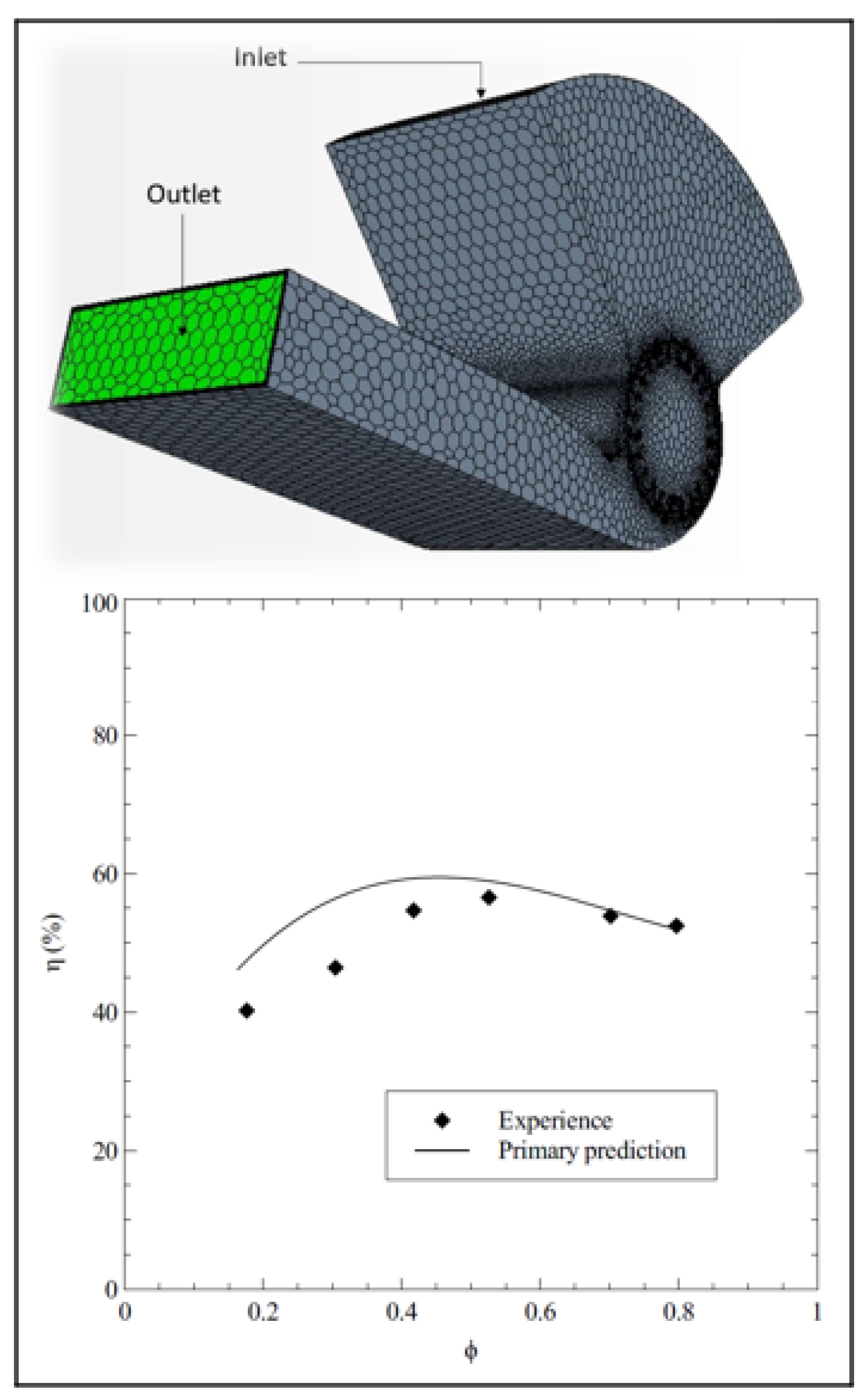
More recently, Himeur et al. [
65] have presented a novel methodology in order to predict the performance of the CFFs by focusing on its correlation with the internal field by applying a multidisciplinary approach.
Figure 12 indicates the applied CFD meshing as well as the predicted efficiency for the applied CFFs’ geometry. When applying CFD simulation as well as an optimization algorithm combined with the internal flow field, there was good agreement with the experimental data, as reported by the authors.


 ,
, 


