1. Introduction
At the current stage of development of heat pump technology, the key issues are energy efficiency and environmental safety [
1,
2]. Due to the need to fulfill international agreements, many traditional refrigerants based on hydrofluorocarbons (HFC) are abandoned to limit the emission of substances that increase the greenhouse effect. Therefore, refrigerants based on natural low-boiling substances are more widely used (e.g., carbon dioxide R744, ammonia R717, and isobutane R600a). One of the refrigerants that can be used in these conditions is CO
2 (R744) since it is safe, non-flammable, not expensive, and widely available on the market.
R744 has advantages over existing analogs, e.g., zero ozone-depleting potential (ODP). Moreover, its global warming potential (GWP) is thousands of times smaller than common refrigerants. Also, CO
2 has several significant thermodynamic properties, including a high heat transfer coefficient, relatively low sensitivity to pressure losses, and relatively low viscosity [
3].
Heat-using thermotransformers are heat and cold supply systems based on waste heat transformation. They are widely used in climatic installations. However, international standards, which permanently update refrigerant requirements, require an improvement of the available design schemes. Therefore, process innovation in heat-using thermotransformers and using environmentally friendly and safe refrigerants is an urgent problem. It is necessary to perform a comparative analysis with existing analogs to evaluate the energy efficiency of the refrigerant R744 in such systems.
While heat-using thermotransformers are becoming widespread, a more detailed study of the operating process and improvements to their working cycle are needed [
4]. The research works [
5,
6] considered the possibility of using CO
2 in heat pump systems. However, this creates a problem associated with high condensation and evaporation temperatures, leading to a transcritical cycle. Simultaneously, in articles [
7,
8,
9], the feasibility of implementing transcritical cycles of heat pump systems on carbon dioxide with a throttle system and an expander system was evaluated [
10,
11]. The authors note that these types can be implemented in one- or two-stage design schemes. Nevertheless, using a two-stage scheme increases the energy efficiency of the working cycle [
12].
Another way to increase the energy efficiency of heat-using thermotransformers is by using combined cycles (i.e., an expansion of CO
2 in the saturated steam region, a regenerative heat exchanger, or a compressor–expander unit) [
13]. Notably, the research work [
14] stated that the combined cycle with CO
2 expansion in the saturated steam region is used for high-performance installations. Expanding the expansion zone and ensuring the outlet temperature in the saturation region is necessary for its implementation. However, the implementation of a combined cycle with a regenerative heat exchanger is possible if the steam is overheated before the compressor. This process can be implemented in a regenerative heat exchanger with relatively low inlet steam superheating and flow expansion to the saturation mode in the expander. As a result, an insignificant difference in the specific adiabatic work occurs, which allows an acceptable cycle coefficient of performance to be maintained [
15].
Simultaneously, the combined cycle with a compressor–expander unit makes it possible to increase the cycle’s conversion factor due to an increase in the temperature difference of the medium heated in the secondary circuit. Particularly, the research works [
16,
17] proposed a heat pump cycle in which expansion with subsequent throttling was implemented.
Also, based on the results of numerical and experimental studies [
18,
19,
20,
21], it can be concluded that CO
2 use is quite effective in a specific range of pressures and temperatures. On the other hand, a possible way to create an energy-efficient heat-using thermotransformer is to switch to the Chistyakov–Plotnikov cycle [
22], combining the abovementioned advantages. Also, the transition from traditional HFC-type refrigerants to natural and safe ones (e.g., R744) additionally increases the environmental safety indicators of the proposed circuit solutions [
23,
24].
Based on numerical studies of R744-based heat-using thermotransformers for combined cycles with expansion in the saturated steam region and a regenerative heat exchanger and with a compressor-expander unit [
25,
26,
27], the proposed design schemes can potentially have relatively high energy efficiency indicators. Remarkably, the main difference from the traditional scheme is the development of the cycle of the CO
2-based heat-use thermotransformer in the heat pump mode.
Due to the analysis mentioned above, the following research gaps were identified. Firstly, refrigeration technologies’ rapid development requires the permanent development of energy-effective and environmentally friendly refrigerants. Also, chlorine- and HFC-containing compounds should be completely abandoned.
Secondly, the results of recent studies are primarily aimed at finding schematic solutions and the most effective modes of operation of technological systems of heat and cold supply through the implementation of critical cycles. Simultaneously, the possibility of waste heat transformation is almost not considered. However, this also can increase the energy efficiency of R744 heat-using thermotransformers.
This article aims to improve the efficiency of heat-recovery thermotransformers with the R744 working medium, which operates based on the Chistyakov–Plotnikov working cycle. To achieve this goal, the following research objectives were formulated. Firstly, existing installations of heat-using thermotransformers should be analyzed with subsequent selection of the most energy-efficient working cycles. Secondly, the development of an improved design scheme for R744 heat-using thermotransformers should be proposed.
Thirdly, a calculation model for evaluating the thermodynamic and mode parameters of the working cycle should be developed for a heat-using thermotransformer with the refrigerant R744 in heat pump mode. Such a model should allow for evaluating the energy efficiency indicators of the proposed cycle. Finally, the obtained energy efficiency indicators should be analyzed, and practical recommendations to introduce R744 heat-using thermotransformers should be formulated.
Overall, the article evaluates the influence of the overheating of carbon dioxide vapors in front of the compressor on energy efficiency.
2. Materials and Methods
2.1. The Initial Design Schemes
After analyzing the existing design schemes of thermotransformers, two main types can be highlighted. The first (
Figure 1) is based on a throttling device (
Figure 1), and the second (
Figure 2) is with a suction gas heat exchanger (SGHE).
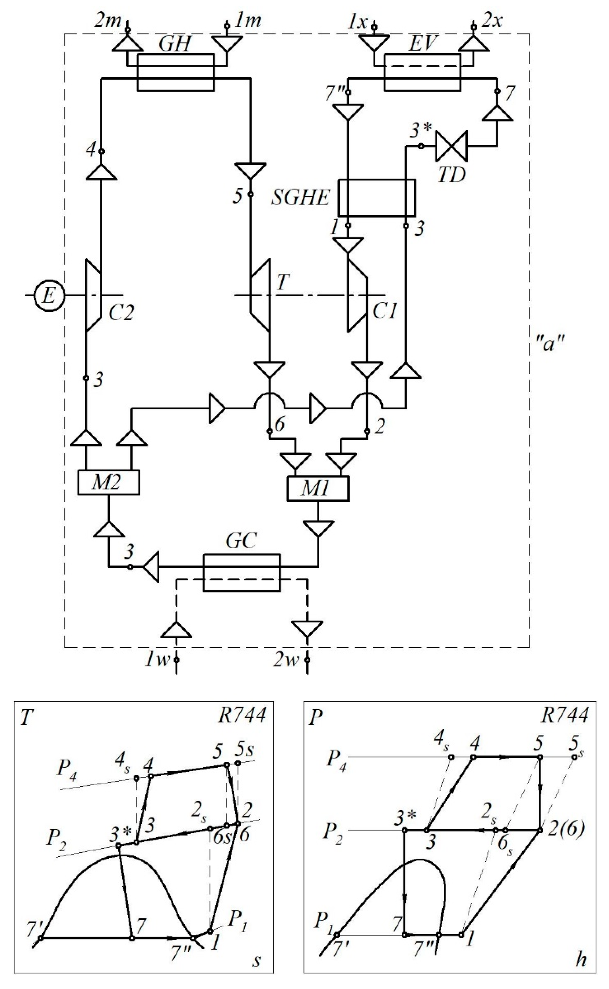
In the basic scheme (
Figure 1), during the process 1–2 in compressor
C1, CO
2 vapor is compressed after the evaporator to the intermediate pressure
p2 of the cycle. The operation of compressor
C1 is realized due to the transfer of mechanical work generated in the gas turbine
T during the expansion of CO
2 from the state at point 5 to the state at point 6. Simultaneously, the conditions
p6 =
p2 and, consequently,
t6 =
t2 are supported.
Next, in the gas cooler GC, the carbon dioxide mixture after the turbine and compressor C1 is cooled to the state at point 3 (process 2–3). This process is implemented due to the heat exchange between carbon dioxide and the heating medium:
- -
In the heat pump mode—the heating of the coolant for the consumer of the heat load (e.g., heating, hot water supply, and so on);
- -
In the cooling mode—the discharge of heat in the process 2–3 into the environment or deeper energy utilization.
After the gas cooler, the flow of CO2 with the parameters at point 3 is divided into two parts. Part M (from the total mass flow through the gas cooler) is returned through the throttle device to the evaporator and then to compressor C1, and part (1 − M) goes to compressor C2 for compression.
In compressor C2, carbon dioxide is compressed to pressure p4 and acquires the state parameters at point 4. Compression is provided due to the introduction of mechanical work from an external engine. A further increase in the energy of the CO2 gas flow for the turbine (state of point 5) is realized in the gas heater GH by supplying heat from the flow of the external coolant (of any generation or aggregate state): . The second part of the carbon dioxide after the gas cooler is throttled to the pressure in the evaporator (process 3–7). Evaporation of the CO2 liquid phase (process 7–1) occurs due to the transfer of low-potential heat from an external source (manufactured or natural), depending on the operation mode of the thermotransformer: . Overall, the total energy resource used for thermal transformation is hybrid. It consists of the energy of the drive motor for the compressor C2 and heat for heating CO2 in the gas heater.
The main difference between the basic scheme (
Figure 2) and the scheme presented in
Figure 1 is that the CO
2 vapors in front of the
C1 compressor are overheated by 5–20 °C due to heat in the
SGHE. Simultaneously, carbon dioxide after the gas cooler is subcooled in the SGHE (process 3–3*). The installation of a regenerative heat exchanger in this scheme provides the following advantages of the cycle. Firstly, it allows higher temperature values,
t2 =
t6, to be obtained and, accordingly, higher heating temperatures of the external coolant for the heat pump operation mode. Secondly, due to the supercooling of the gas under intermediate pressure after throttling, it also allows saturated steam (state of point 7) with less dryness to be obtained and the heat load on the evaporator to be increased.
Therefore, the proposed design scheme is rational for the heat pump mode of operation of the thermotransformer.
2.2. The Calculation Model
Below, a calculation model for the initial and proposed design schemes is developed under certain assumptions. Firstly, the model assumes the equality of the parameters of the refrigerant when mixing after the turbine and compressor C1. In other words, the parameters at point 2 are equal to those at point 6. Secondly, the parameters at points 2s and 4s are determined under conditions of isentropic compression in compressors C1 and C2, respectively. Thirdly, the parameters at points 2 and 4 are determined under the conditions of polytropic compression in compressors C1 and C2, respectively.
Under these assumptions, the temperature at point
3 is determined as follows:
where ∆
tur is the under-recovery rate used to assess the energy efficiency of the design scheme.
Point 5s is a point that assumes the state of the refrigerant at the turbine inlet. It was introduced so that the final state in the refrigerant’s isentropic expansion at 5s–6 was characterized by the parameters at point 6, which are equal to the parameters at point 2. This assumption is acceptable in the given interval of pressure changes, p5–p2.
Also, the inlet pressure in turbine
T equals the outlet pressure from the gas heater
GH (
p4 =
p5). It is determined as follows:
where
β = 1.2–1.8 is the pressure ratio for the compressor
C2.
The throttling process is considered isoenthalpic. Therefore, h7 = h3, and other parameters at point 7 are determined under the condition p7 = pev.
Within the intersection of external material and energy flows (
Figure 1, contour “
a”), the energy balance is as follows:
The energy balance equation, Equation (3), from the side of the refrigerant takes the following form:
where
le,C2 = (
h4—
h3)/
ηmech,C2 is the specific effective work of the compressor
C2.
The refrigerant mass flow rate balance is as follows:
After considering the mass flow rate through the evaporator and, accordingly, through the compressor
C1,
the mass flow through the gas cooler takes the following form:
After equal transformations and considering that for the throttling process
h7 =
h3,
The ratio
M becomes equal to
where
li,C2 =
h2 −
h1 is the specific work of the compressor
C1; ∆
q =
qGH—
qGC = (
h5 −
h4) −
− (h2—h3).
Based on the heat load transferred to the gas cooler, the mass flow can be determined as follows:
The energy efficiency of the working cycle is as follows:
Also, the cycle coefficient of performance for primary energy resources takes the following form:
where
COPTG = 0.9 and
COPEG = 0.3 are the energy efficiency of thermal and electricity generation, respectively.
For the design scheme presented in
Figure 2, Equation (5) takes the following form:
or after considering the ratio
M:
For the option with the SGHE, the balance equation is as follows:
Therefore, h7″ − h3* = h1—h3, and Equation (21) completely repeats Equation (9). Moreover, Equations (10)–(20) can be applied to calculate this option.
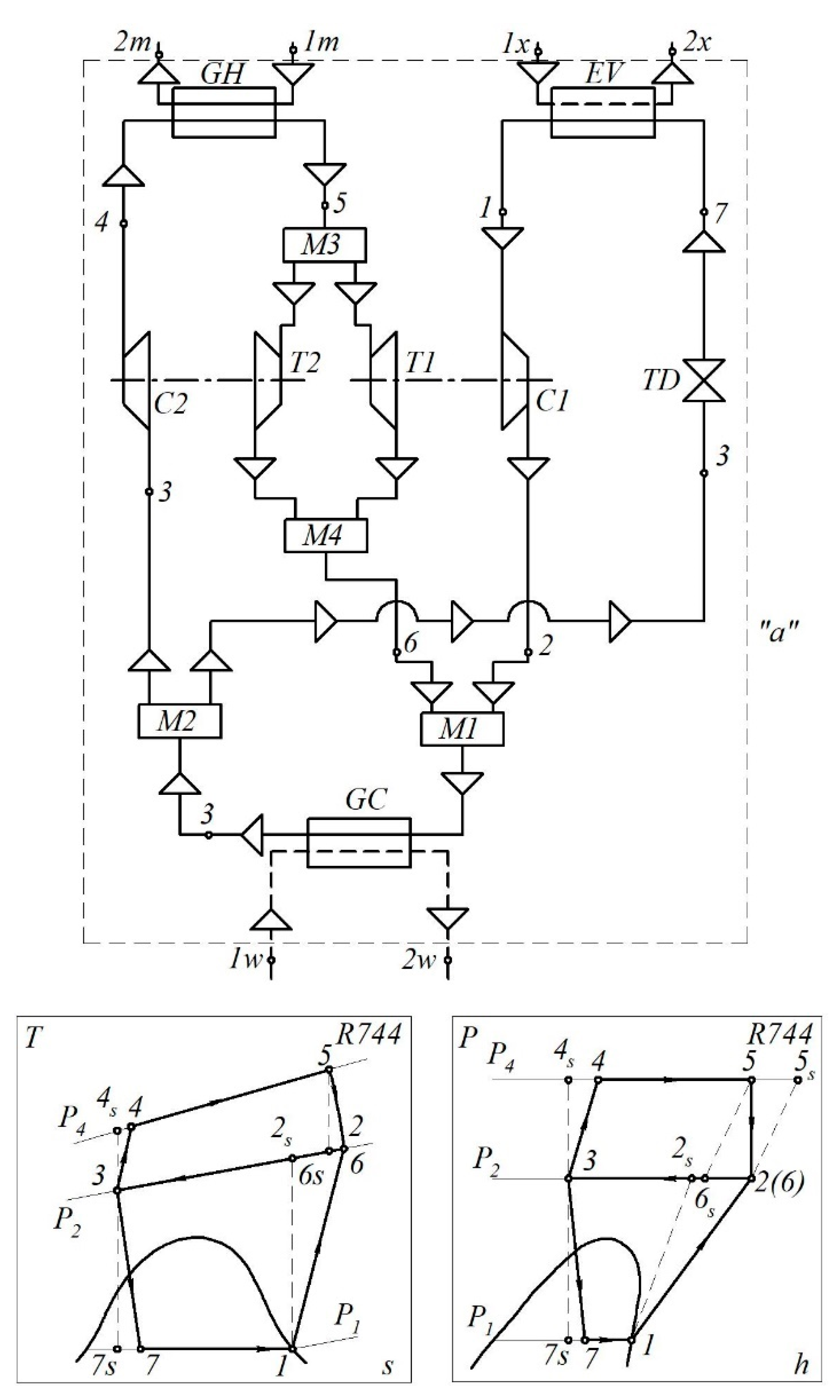
2.3. The Proposed Design Schemes
The proposed design schemes and working cycles are presented in
Figure 3 and
Figure 4. The functioning of thermotransformers, according to alternative schemes, involves switching the drive for the compressor
C2 from the gas turbine
T2. In this case, after the gas heater, the flow of CO
2 is divided into two turbines in proportion to the mechanical work required to drive compressors
C1 and
C2, respectively. The turbines operate in the same range of parameters (process 5–6). Due to the change in the energy supply to drive the compressor
C2, the thermal load on the gas heater increases (due to the increase in the mass flow rate of both media in the heater). Such a scheme is more energy-effective when using resettable coolants. The operation of other system components is similar to the basic schemes shown in
Figure 1 and
Figure 2.
2.4. The Calculation Model of the Proposed Design
The energy balance equation for the design scheme presented in
Figure 3 within the contour “
a”,
has the following solution from the side of the refrigerant:
As for the initial design scheme, the ratio
M of the mass flow rate through the evaporator is also considered:
After an equal transform, this equation takes the following form:
Therefore, the ratio
M takes the following form:
The mass flow rates, , , and are determined by the same equations, Equations (13)–(15), as for the initial design scheme. However, in contrast to the initial scheme, the mass flow rate of the refrigerant after the gas heater is divided into two flows that pass through the turbines T1 and T2 with parts Z and (1 − Z), respectively.
Therefore, the following partial relations are introduced:
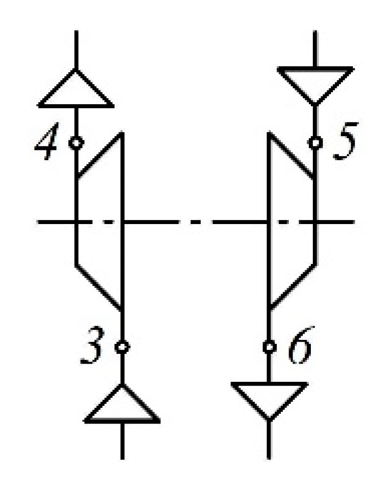
Thus, for the design scheme presented in
Figure 5, the following relations can be written:
Overall, the energy efficiency of the cycle in the heat pump mode is as follows:
3. Results
The energy efficiency calculation results obtained for the initial and proposed design schemes are presented below.
Calculations were carried out for different operating modes of the thermotransformer depending on the pressure ratio between compressors
C1 and
C2.
Table 1 shows the calculation of the mode parameters of the refrigerant R744 at the nodal points of the cycle for the basic scheme (
Figure 1) and the proposed scheme (
Figure 3).
Table 2 shows the same for the basic scheme (
Figure 2) and the proposed scheme (
Figure 4).
The results are given for one mode of operation; however, there are about 50 operating modes.
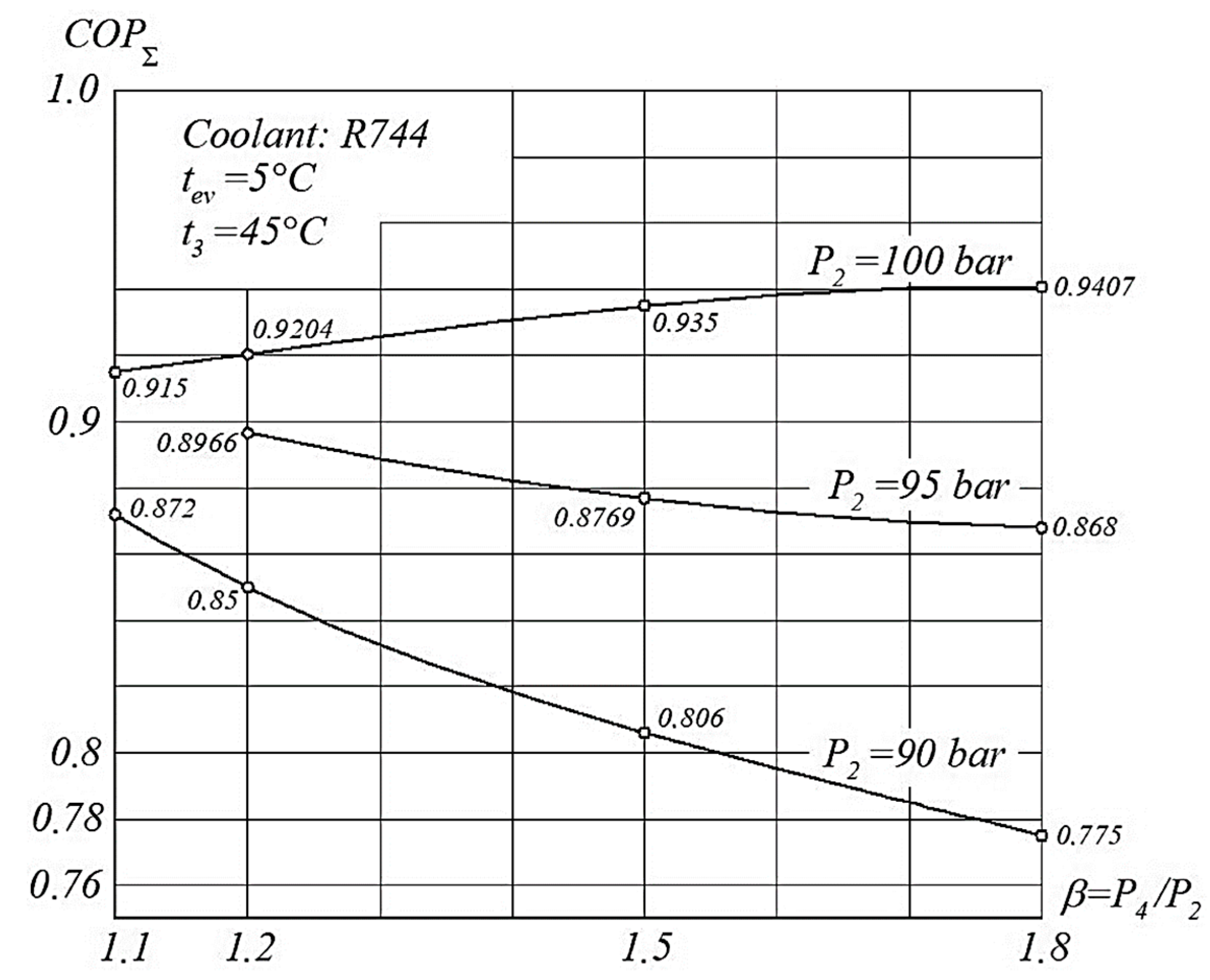
Figure 6 shows the cycle coefficient of the performance calculation results for the initial design scheme presented in
Figure 1.
Figure 6 shows that at the same value of the pressure ratio
β =
p4/
p2, but at different values of the pressure
p2 at the inlet to the compressor
C1, the value of the cycle conversion factor will be different. Particularly, for
β = 1.2, the efficiency of the cycle will be greatest at a pressure value of
p2 = 100 bar. The same will be observed with an increase in the pressure rate
β.
Simultaneously, if the pressure ratio in compressor C2 is increased, at the pressure values of p2 = 90 bar and p2 = 95 bar at the outlet of compressor C1, the value of ηΣ will decrease for a certain pressure value p2. Overall, the cycle coefficient of the performance for the initial design scheme is ηΣ = 0.775 − 0.941.
Figure 7 presents the calculation results of the cycle coefficient of the performance for the proposed scheme presented in
Figure 3.
Figure 7 shows that for the proposed scheme, as well as for the basic one, at the same value of the pressure ratio
β =
p4/
p2, but at different values of the pressure
p2 at the input to the compressor
C1, the value of the cycle conversion factor will be different. However, the main difference is that with an increase in the pressure
p2 at the outlet of the compressor
C1, the value of the conversion factor of the cycle constantly increases in the range of
β = 1.2–1.8. Overall, the cycle coefficient of the performance for the initial design scheme is
ηΣ = 1.010–1.096.
After analyzing the results presented in
Figure 6 for the basic scheme and
Figure 7 for the proposed scheme, it can be concluded that using a new heat-using scheme makes it possible to increase the conversion factor of the cycle by an average of 18.5%.
Moreover, an interesting feature of the curves presented in
Figure 6 and
Figure 7 is that an increase in the pressure ratio in the compressor
C2 leads to an increase in the cycle coefficient of the performance,
COPΣ.
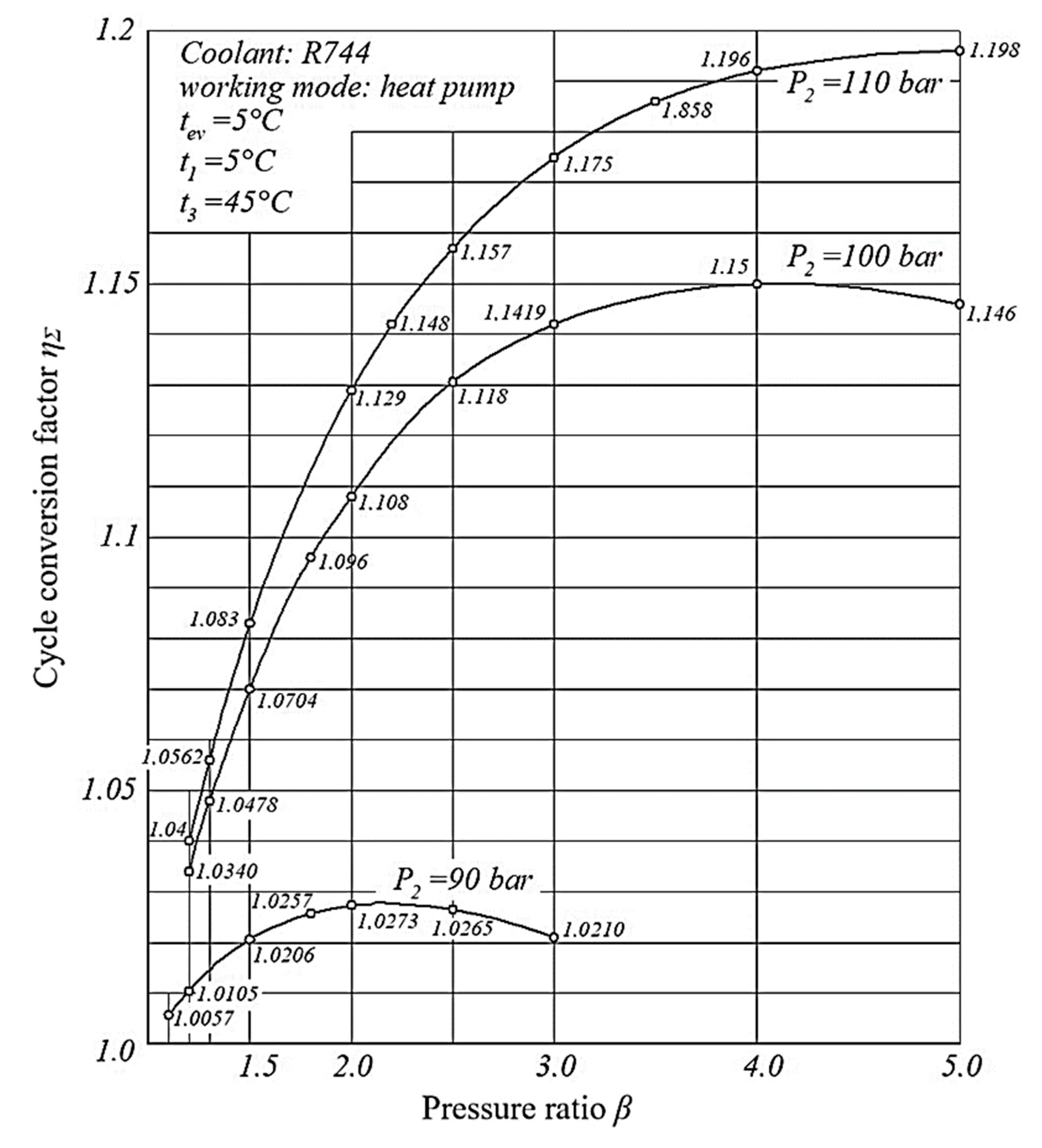
Figure 8 presents the proposed design scheme’s cycle coefficient of the performance calculation results for the pressure ratio
β = 1.1–5.0 in the compressor
C2.
Figure 8 shows that with an increase in the degree of the pressure ratio in a range of
β = 2.0—5.0, the curves of the cycle conversion factor for the pressure
p2 = 90 bar reach the extremum at
β = 2.2, and for
p2 = 100 bar at
β = 4.0. Therefore, the most significant values of the cycle conversion coefficients for
p2 = 90 bar will be in the interval
β = 1.8–2.5, and for
p2 = 100 bar at
β = 3–5.
For the value of the suction pressure in the compressor C1 near p2 = 110 bar, the curve of the values of the conversion coefficients of the cycle will have a constantly increasing character. Therefore, the highest efficiency ratio will be in the range of β = 4–5.
Another energy efficiency indicator is the dependence of the cycle coefficient of performance,
ηΣ, on the suction temperature,
t1, in the compressor
C1 (
Figure 9).
From
Figure 9, an increase in the suction temperature of the compressor
C1 increases the energy efficiency of the proposed design scheme of the R744 heat-using thermotransformer. Therefore, the most significant cycle coefficient of the performance is reached at
t1 = 25–30 °C.
4. Discussion
Thus, after analyzing the results obtained in
Section 2 and evaluating the numerical calculation results for the initial and proposed design schemes presented in
Figure 1,
Figure 2,
Figure 3 and
Figure 4, it is possible to determine a number of advantages of using the proposed design schemes with a throttling device (
Figure 3) and an SGHE (
Figure 4). The primary advantage is the rejection of the drive motor, which is necessary to drive the compressor
C2 in the initial design schemes.
Also, in the proposed design schemes, the equality of the capacities of the compressor
C1 and the turbine
T1, located on a joint shaft, is ensured due to regulating mass flow rates in these devices. The cycle coefficient of performance is also increased for the proposed design scheme compared to the previous research results [
7,
8,
9,
10,
11].
The results obtained in
Section 3 show that the energy efficiency of the proposed design schemes is higher than that of the initial ones. It is increased with an increase in the pressure ratio in the compressor. Also, the efficiency of the proposed design schemes is increased by an increase in this ratio and the suction pressure in the compressor. This is explained by separating the mass flow of the refrigerant after the gas heater into two flows that pass through the turbines
T1 and
T2.
When creating a calculation model, as presented in
Section 2, the given assumptions can be considered a research limitation. They do not significantly affect the accuracy of the obtained results, although their reduction significantly complicates the proposed model. Nevertheless, the results’ reliability is proven by the relative calculation error, which does not exceed 5%. This value is sufficient for the evaluation of energy efficiency indicators.
Overall, this research presents the numerical calculation results for heat-using thermotransformers according to the proposed design model. The novelty of this article is the development of a model for evaluating the efficiency of thermotransformers.
A comparison with the experimental studies for existing analogs [
12,
13,
14,
15,
16,
17] at different operation modes and refrigerants will be carried out in further studies. Finding an optimal value of the pressure ratio between compressors
C1 and
C2 is also one of the next stages.
5. Conclusions
As a result of the analysis of existing heat-using thermotransformers, the two most effective design schemes were determined. The first is a design scheme with a throttling device, and the second is a suction gas heat exchanger (SGHE), which operates as an evaporator. These schemes have a cycle coefficient of performance of 0.775–0.941. However, using an SGHE before the compressor enables an overheating of the refrigerant at the inlet of the compressor.
Heat recovery units were proposed to increase the energy efficiency of the initial design schemes. Due to the proposed design solutions, they allowed for the abandonment of the use of an external engine to drive the compressor. This made it possible to reduce electrical energy consumption and spend it on starting the turbine only. As a result of using new heat utilization schemes, the conversion factor of the cycle has increased up to 1.010–1.096.
A calculation model was developed to determine the thermodynamic and mode parameters of the cycle for a heat-using thermotransformer with the refrigerant R744 operating at the heat pump mode. Additionally, a calculation model was developed to evaluate the proposed cycle’s energy efficiency indicators and assess the expediency of implementing the proposed design scheme. As a result, it was shown that using the proposed heat utilization schemes allows the cycle coefficient of performance to be increased by an average of 18.5%.
An analysis of the obtained energy efficiency indicators showed that implementing the proposed design scheme allows the energy efficiency of heat-using thermotransformers to be increased by an average of 23%, depending on the suction pressure in the compressor.


 ,
, 


