Article

The Effect of Nozzle Configuration on Adsorption-Chiller Performance

1
Department of Thermal and Fluid Flow Machines, Faculty of Energy and Fuels, AGH University of Krakow, al. A. Mickiewicza 30, 30-059 Krakow, Poland
2
JWA Polska, ul. Ks. I. J. Skorupki 11/1, 31-519 Krakow, Poland
*
Author to whom correspondence should be addressed.
Energies 2024, 17(5), 1181; https://doi.org/10.3390/en17051181
Submission received: 14 January 2024 / Revised: 19 February 2024 / Accepted: 27 February 2024 / Published: 1 March 2024
(This article belongs to the Special Issue Cooling and Heat Exchange Systems)

Abstract

:
Broadly defined climate protection is a powerful incentive in the search for environmentally friendly refrigeration technologies. Adsorption chillers are considered to be one such technology; however, their main disadvantages include a low cooling capacity, a low energy efficiency ratio (EER), and cyclic operation. Thus, a great deal of effort is being put into improving adsorption-chiller performance. In this paper, the influence of the spray angle, the number of nozzles, and the water flow rate through the nozzles on adsorption-chiller performance was investigated. Adsorption-chiller performance was investigated mainly in terms of the cooling capacity (CC), the energy efficiency ratio (EER), and the specific cooling power (SCP). The results indicated that the chiller’s cooling capacity increased from about 210 W to 316 W and that the EER increased from 0.110 to 0.167 when the spray angle of the nozzles was increased from 90° to 120°. It was also reported that increasing the flow rate of water through the nozzles did not improve the average cooling capacity or the other performance parameters but resulted in more stable operation of the chiller. Additionally, using six nozzles instead of three improved the average cooling capacity and EER tenfold.

1. Introduction

Air conditioners use about 20% of the total electricity used in buildings around the world today, and moreover, demand for air conditioners and refrigerators is growing; it is estimated that by 2050, around 2/3 of the world’s households could have air conditioners [1]. The refrigeration and air conditioning sector is currently dominated by vapor-compression systems, the application of which is associated with several problematic issues, e.g., the use of ozone-depleting and global-warming-causing refrigerants [2]. Therefore, the modern development of refrigeration is closely linked to global climate change, and refrigeration technologies other than vapor compression are in demand.
One of the refrigeration technologies gaining more and more attention is adsorption refrigeration technology. Adsorption chillers possess some unique features, including the possibility of being powered with low-temperature heat and using natural and eco-friendly refrigerants, which makes them a promising and competitive alternative to classic vapor-compression refrigeration units [3]. Additionally, adsorption chillers give the opportunity to generate cold and desalinate water simultaneously [4]. Nevertheless, the energy efficiency ratio (EER) of adsorption chillers is usually lower than the EER of vapor-compression refrigerators [5]. Furthermore, adsorption chillers have a large mass and size in relation to the obtained cooling capacity [6]. Therefore, much effort is being put into improving overall adsorption-chiller performance in terms of EER and CC.
Various techniques have been investigated and implemented to improve adsorption-chiller performance. These techniques include but are not limited to increasing the temperature of hot water that is used to regenerate the sorbent [7], using steam instead of water to regenerate the sorbent [8], optimizing the adsorption/desorption cycle times [9], and using various adsorption working pairs [10]. The most commonly used adsorption working pair is silica gel/water, in which water plays the role of the refrigerant. Bearing in mind that the operating pressure of the evaporator must be lowered far below 10 kPa to evaporate water at a temperature below 20 °C and that the chiller should be as small and light as possible, a special evaporator design is required [11]. Generally, three types of evaporators can be used in adsorption chillers: flooded, capillary-assisted, and falling film, of which falling film evaporators are the most popular in the case of adsorption chillers [12].
A falling film evaporator is usually made of a stainless steel cylindrical tank, inside which chilled water flows through the pipes, while the refrigerant (usually water) is sprayed on the surface of the pipes [13]. Thus, the way in which the water is sprayed significantly affects the evaporation rate and overall evaporator performance. For example, Woo et al. [14] investigated two brine feeders in an evaporator, i.e., a perforated plate and a spray nozzle. It was found that the specific cooling capacity of the adsorption chiller with the spray nozzle was approximately 12–30% higher than with the perforated plate. Therefore, nozzles are often used to spray a fluid on a heat transfer area.
Each nozzle is characterized by the following features: the capacity, the spray angle, and the nature of the fluid discharge. Changing some of the above features also requires changing the design of the nozzle. In the case of water nozzles, the following types exist: full cone, hollow cone, flat fan, misting, and some other types [15]. Nevertheless, each nozzle works in the same way. With the help of special guide vanes, the fluid flowing into the nozzle is directed to become swirled. The diameter of the element decreases closer to the exit of the nozzle, and the diameter of the nozzle expands again by a few millimeters before the exit. Thanks to this procedure, the fluid changes its speed, and its spread is controlled. It should be noted that the nozzle as an element has no moving parts; therefore, the fluid flow must be driven by another element, for example, a pump.
According to Cheng et al. [16], the nozzle affects the spray characteristics and heat transfer performance. Therefore, there is a great deal of work concerning the effect of various nozzle features, such as nozzle height [17], nozzle cross-section area [18], the number of nozzles [19], and many others, which can be found in [20], on heat transfer and overall nozzle performance.
Besides the factors listed above, the spray angle of the nozzle can be indicated as a feature that affects both the spray pattern and droplet size [21]. Droplet distribution and droplet motion, in turn, influence the evaporation rate of sprayed droplets [22]. Therefore, Chang and Yu [23] developed an analytical expression that allows the calculation of the optimal spray angle for an evaporator. Additionally, it was concluded that the optimal spray angle depends on the geometry of the evaporator, especially the distance between the nozzles and heater tubes and the outer diameter of the heater tubes.
Although numerous papers address the problems of nozzles in the evaporator, the majority of them consider only the evaporation process without analyzing its impact on the entire system. Thus, this paper presents the results of experimental studies on the effect of evaporator nozzle features on adsorption-chiller performance. The spray angle and the number of nozzles were taken as nozzle features. Adsorption-chiller performance was analyzed in terms of cooling capacity, specific cooling power, and the temperature inside the evaporator, as well as the pressure inside the evaporator, condenser, and beds of the adsorption chiller.

2. Materials and Methods

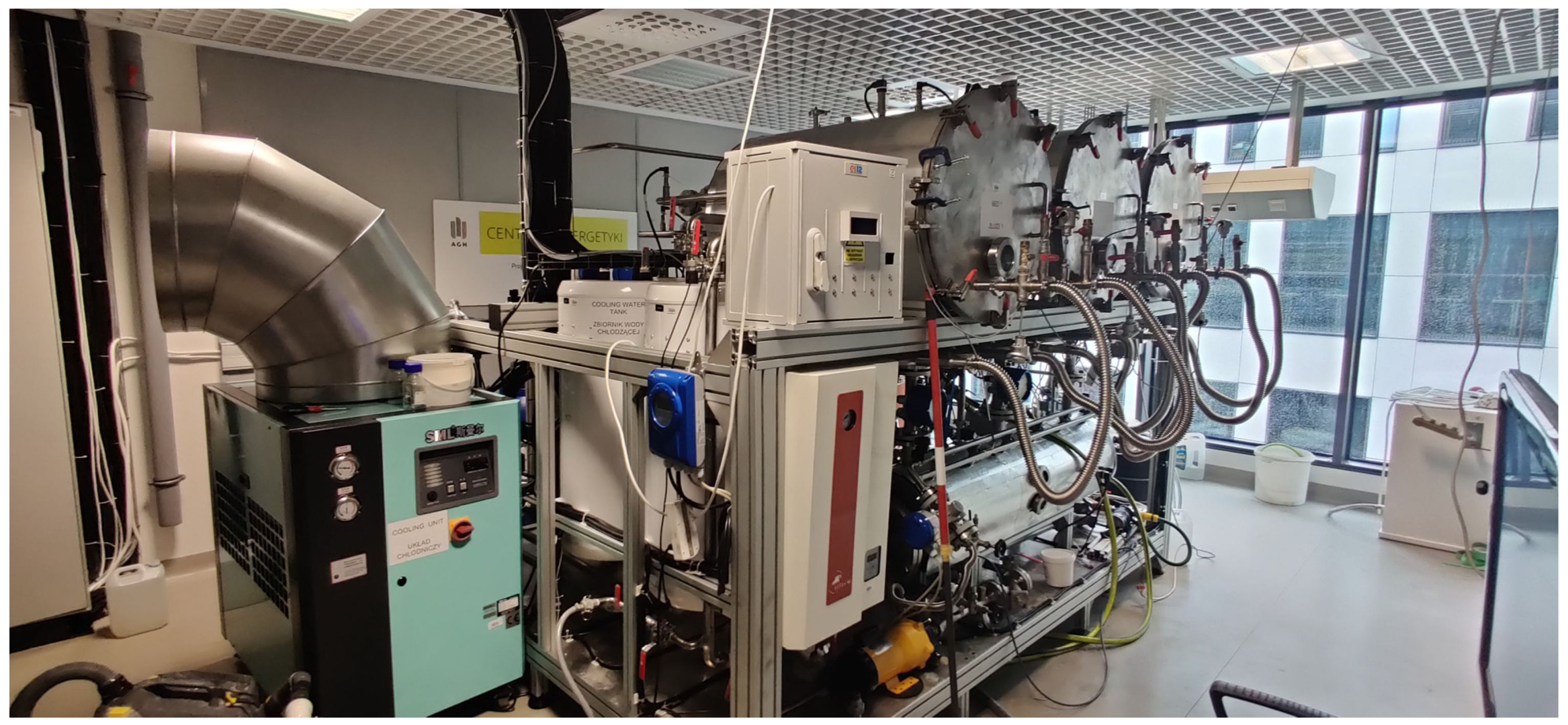
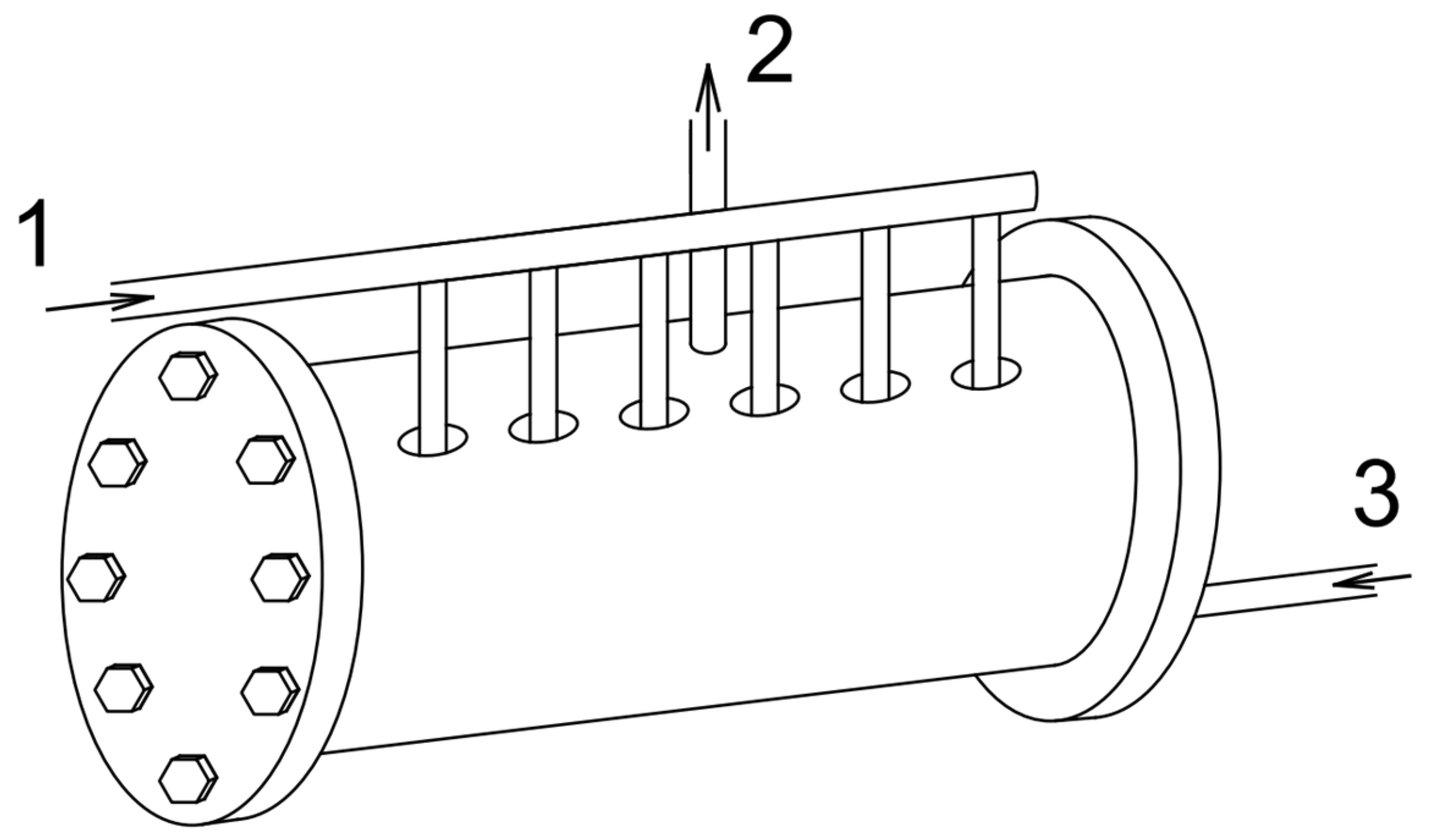
2.1. Experimental Setup

The experiments were conducted with an adsorption chiller located at the Center of Energy, which is a part of AGH University of Krakow (Kraków, Poland). The investigated adsorption chiller (Figure 1) possesses three beds and can operate in a chilling mode or a water desalination mode. It is worth noting that if the chiller is operating in cooling mode, only two beds are used, whereas if the chiller is operating in water desalination mode, it uses three beds.
The investigated adsorption chiller, a diagram of which is shown in Figure 2, is equipped with an evaporator (1), bed number 1 (2.1), bed number 2 (2.2), a condenser (3), a pump (4), and a U-tube (5).
Water, which acts as a refrigerant, is sprayed through nozzles into the evaporator. There, the water receives heat from chilled water, which is flowing through the coil. As a result, the sprayed water evaporates and goes into one of the beds. In the bed, the water vapor is adsorbed by the sorbent (silica gel). The adsorption is an exothermic process, and heat released during the adsorption is removed by cooling water. After the adsorption is complete, the flow of cooling water through the bed is cut off, and the flow of heating water is triggered. Consequently, desorption occurs, and the desorbed water vapor with high pressure flows into the condenser, where it condenses, giving off heat. Then, the condensate flows into the evaporator through the U-tube, whose function is to reduce pressure. After that, the entire process repeats. It must be noted that the beds work alternately, i.e., when the adsorption takes place in the first bed, desorption is realized simultaneously in the second bed.
The basic operating parameters of the investigated adsorption chiller are summarized in Table 1.
The measuring devices and the monitored parameters are listed in Table 2.

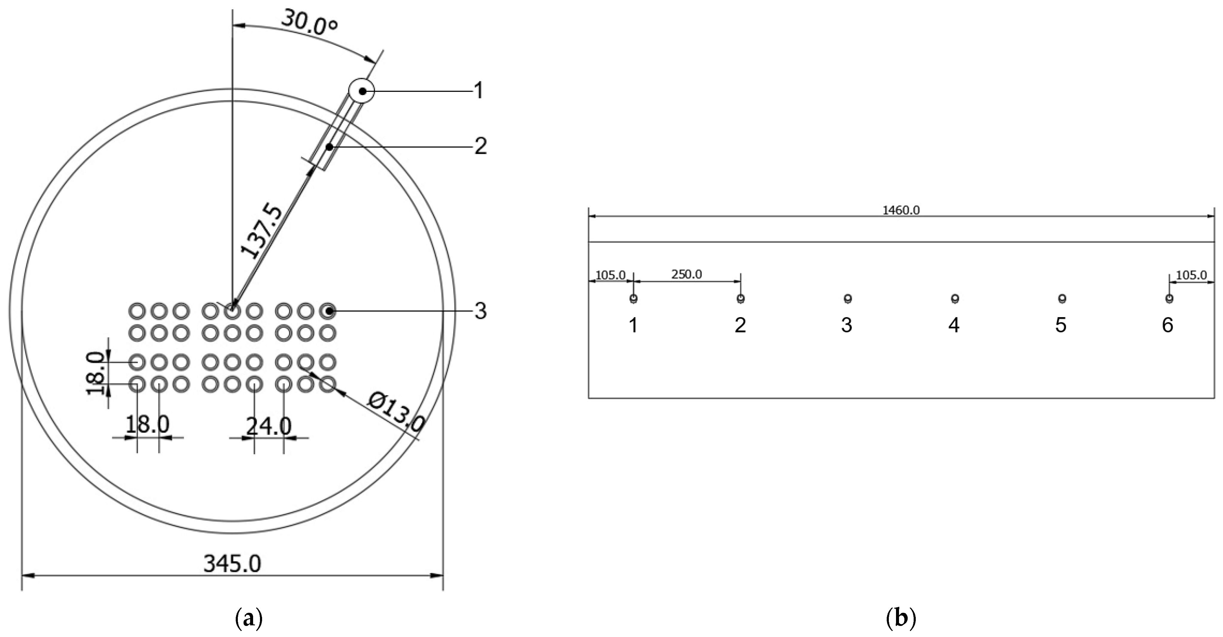
2.2. Nozzles in the Evaporator

The evaporator is one of the key components of the adsorption chiller. The evaporator is a cylindrical horizontal tank filled to about one-third of its volume with water. However, to increase the effectiveness of the evaporation, the water from the evaporator is circulated by a pump and sprayed into the evaporator by the nozzles, as schematically shown in Figure 3. The sprayed water receives heat from the chilled water and evaporates at a temperature of about 15 °C. The water can evaporate at such a low temperature due to low pressure, i.e., about 1–2 kPa. The chilled water flows through the coils inside the evaporator.
As mentioned in the previous paragraph, the water is sprayed into the evaporator by the nozzles (Figure 4). Six nozzles are mounted at an angle of approximately 30° to the vertical axis of symmetry of the evaporator. The nozzles cannot be mounted vertically to the evaporator because the water-vapor pipes are mounted vertically. When the evaporator is working with three nozzles, nozzle numbers 2, 4, and 6 are working, while nozzle numbers 1, 3, and 5 are unscrewed and the holes are plugged. The nozzles are placed at equal distances from each other so that the water sprayed through them covers as much of the evaporator surface as possible. The flow rate of water to the nozzles is regulated by the valves.
Two types of nozzles can be used interchangeably in the investigated adsorption chiller—type 1 nozzles (Figure 5a) and type 2 nozzles (Figure 5b). The difference between these two types of nozzles is the spray angle; the spray angles of type 1 and type 2 nozzles are 120° and 90°, respectively. The flow rate of water through the nozzle as a function of water pressure is summarized in Table 3.

2.3. Experimental Procedure and Measuring Devices

A total of 5 experiments were performed to test the effect of the spray angle and the number of working nozzles on adsorption-chiller performance. During those experiments, the adsorption chiller worked in the two-bed mode, and the cycle time conditions were as follows:
  • 300 s—adsorption/desorption;
  • 30 s—heat recovery;
  • 60 s—bed regeneration.
In the first part, the effect of the spray angle on adsorption-chiller performance was investigated. Thus, in the first two experiments (cases A and B), six type 1 nozzles (spray angle of 120°) and six type 2 nozzles (spray angle of 90°) were used, and the total flow rate of water was 400 L/h, which gives about 67 L/h/nozzle. In the next two experiments (cases C and D), six type 1 nozzles (spray angle of 120°) and six type 2 nozzles (spray angle of 90°) were used, and the total water flow rate through the nozzles was 200 L/h, which gives about 33 L/h/nozzle. In the second part of the research, the effect of the number of nozzles on adsorption-chiller performance was investigated. In this part (case E), the number of working nozzles was reduced to three, and their spray angle was 90° (type 2 nozzles). The total water flow rate in the last experiment was 200 L/h, which gives a flow rate per nozzle of about 67 L/h/nozzle. The conducted experiments are listed in Table 4.
Each experiment lasted about two hours; in the first hour, the experimental setup was prepared and turned on, and the working parameters of the device were stabilized. After the device reached a steady state, the proper measurement began. The operating parameters, which are listed in Table 2 in Section 2.1, were saved on a personal computer every 1 s. Besides the parameters listed in Table 2, the cooling capacity (CC), energy efficiency ratio (EER), and specific cooling power (SCP) were calculated as shown in Equations (1)–(3) [24]:
C C = V ˙ c h · ρ · c p · T c h , i n T c h , o u t ,
E E R = C C · t V ˙ h · ρ · c p · T h , i n T h , o u t · t ,
S C P = C C m s ,
where cp is the specific heat capacity of water (assumed to be 4200 J/(kgK)), V ˙ is the flow rate (m3/s), ρ is the density of water (assumed to be 1000 kg/m3), T is the temperature (°C), t is the time (s), and ms is the mass of sorbent (10 kg). The subscripts ch, h, in, and out stand for chilled water, heating water, inlet, and outlet, respectively. The uncertainties of the CC, EER, and SCP were calculated from the general formula for error propagation [25]:
δ f = i = 1 k 𝜕 f 𝜕 x i δ x i 2 ,
where δf is the uncertainty of variable f, x is the measured value, and δx is the uncertainty of the measured value. The calculated maximum uncertainties of the CC, EER, and SCP are 66 W, 0.034, and 6.6 W/kg, respectively.

3. Results

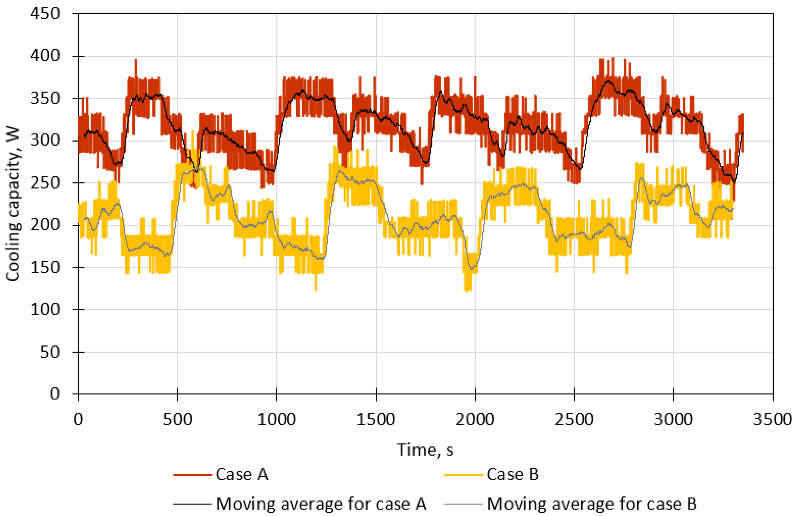
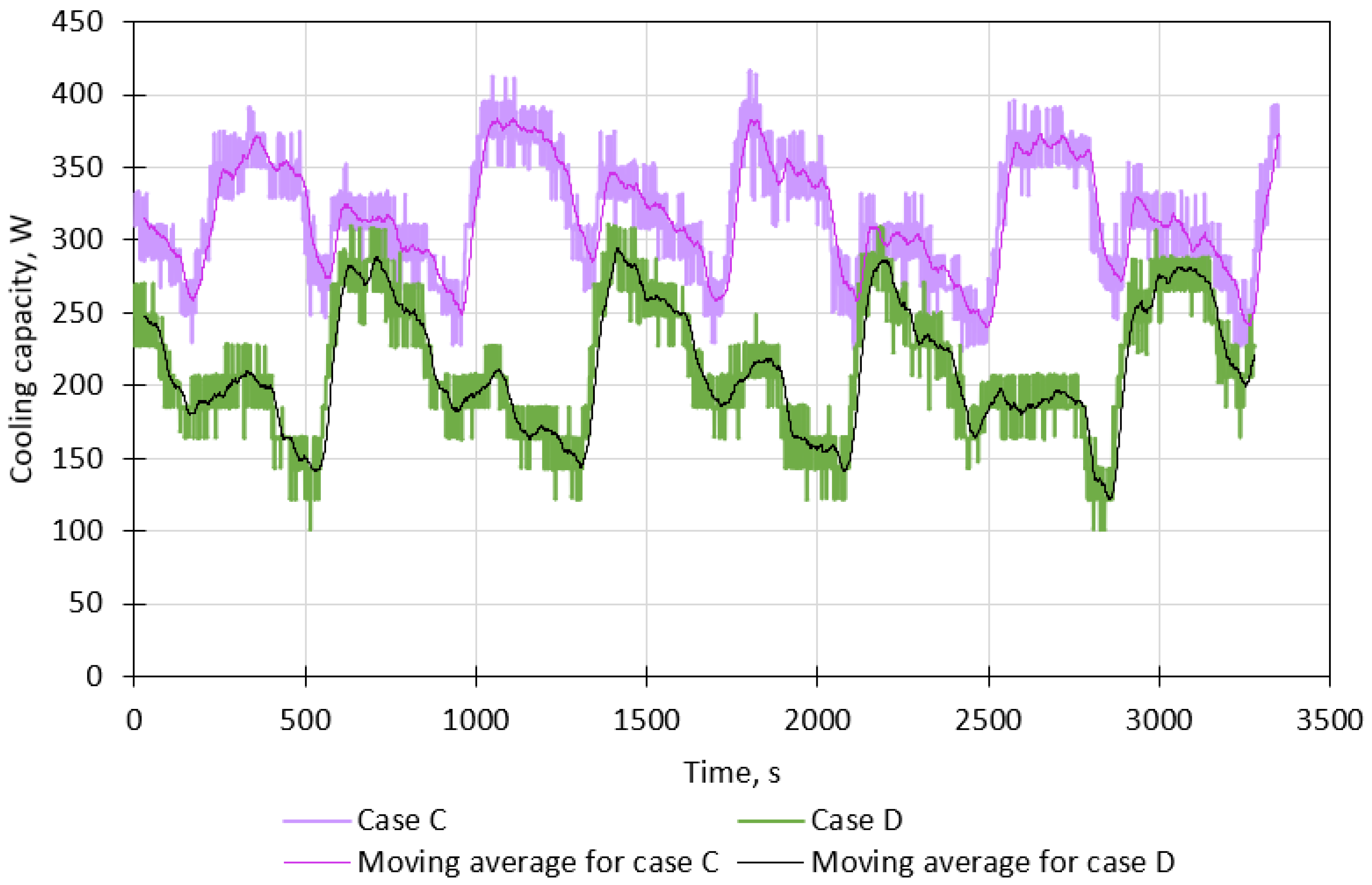
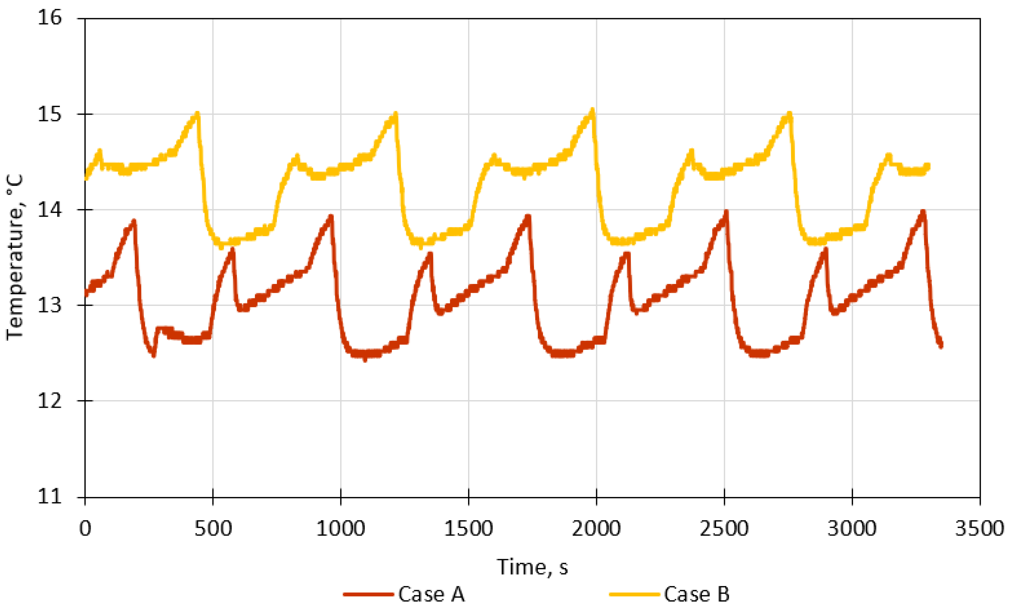
3.1. The Effect of Spray Angle on Adsorption-Chiller Performance

The cooling capacity of the adsorption chiller with six type 1 nozzles (case A) and six type 2 nozzles (case B) and a total flow rate of water through the nozzles of 400 L/h is shown in Figure 6. As can be seen, the cooling capacity for case A varies from about 250 W to 375 W (average value of 316 W, standard deviation of 31 W), while the cooling capacity for case B varies from about 150 W to 300 W (average value of 210 W, standard deviation of 32 W). Therefore, in the analyzed case, a higher spray angle is better in the context of the cooling capacity of the adsorption chiller. Water evaporation is a very complicated process, and it depends on many factors. The observed increase in cooling capacity for the greater spray angle (120°) can be attributed to the following reasons. Firstly, increasing the spray angle can reduce the droplet size and improve the uniformity of droplets, which has a positive effect on evaporation performance [26]. Secondly, with a greater spray angle, the water droplets fall on a larger surface area of the tube, from which they receive heat. It must be remembered that the evaporation rate is proportional to the free surface area of the evaporating liquid. Additionally, according to Dai et al. [27], the thickness and flow mode of a falling film have a significant impact on the overall heat transfer coefficient between the tube and the falling film. Thus, the possibility cannot be excluded that the spray angle affects the falling film’s thickness and flow mode, which results in an improved heat transfer coefficient, a faster evaporator, and greater cooling capacity.
Figure 7 presents the cooling capacity of the adsorption chiller with six type 1 nozzles (case C) and six type 2 nozzles (case D) and a total flow rate of water through the nozzles of 200 L/h. The cooling capacity for case C varies from about 225 W to 425 W (average value of 319 W, standard deviation of 41 W). The cooling capacity for case D varies from about 100 W to 325 W (average value of 211 W, standard deviation of 44 W). Comparing the results for water flow rates of 400 L/h (cases A and B) and 200 L/h (cases C and D), it can be concluded that the average cooling capacity is similar for both water flow rates. However, the cooling capacity in the case of a lower water flow rate, i.e., 200 L/h, is more unstable, which is evidenced by a greater standard deviation value.
The temperature inside the evaporator for a 400 L/h water flow rate and six type 1 nozzles (case A) and six type 2 nozzles (case B) is shown in Figure 8. In case A, the temperature inside the evaporator varies from about 12.5 °C to 14.0 °C (average of 13.06 °C, standard deviation of 0.40 °C). On the other hand, the temperature inside the evaporator in case B fluctuates between 13.5 °C and 15.0 °C (average of 14.24 °C, standard deviation of 0.39 °C). Therefore, a greater spray angle results in a slightly lower temperature inside the evaporator because the water droplets are sprayed on a greater surface area, and thus, the evaporation rate is higher, as it is proportional to the surface area.
Figure 9 shows the temperature inside the evaporator for a water flow rate of 200 L/h and two types of nozzles. The temperature inside the evaporator for type 1 nozzles (case C) varies from approximately 12.0 °C to 14.0 °C (average of 12.91 °C, standard deviation of 0.61 °C), while the changes for type 2 nozzles (case D) are from about 13.2 °C to 15.2 °C (average of 14.12 °C, standard deviation of 0.60 °C). Therefore, using type 1 nozzles results in a lower temperature inside the evaporator than using type 2 nozzles. Additionally, comparing the results obtained for the water flow rates of 400 L/h (cases A and B) and 200 L/h (cases C and D), one can say that in both cases, nozzles with a greater spray angle provide a lower average temperature inside the evaporator. However, the operation of the evaporator is more unstable when the water flow rate is lower, which is evidenced by a higher standard deviation value.
Figure 10 presents the SCP for a water flow rate of 400 L/h and two types of nozzles. The SCP is greater for type 1 nozzles (case A), falling within the range of 25–40 W/kg, than for type 2 nozzles (case B), falling within the range of 15–30 W/kg. Furthermore, the average SCP and its standard deviation in case A are 31.6 W/kg and 3.1 W/kg, respectively. In case B, the average SCP and its standard deviation are 21.0 W/kg and 3.2 W/kg, respectively.
Figure 11 presents the SCP for a water flow rate of 200 L/h and two types of nozzles. The SCP is greater for type 1 nozzles (case C), falling within the range of 25–42 W/kg, than for type 2 nozzles (case D), falling within the range of 10–33 W/kg. Furthermore, the average SCP and its standard deviation in case C are 31.9 W/kg and 4.1 W/kg, respectively. In case D, the average SCP and its standard deviation are 21.1 W/kg and 4.4 W/kg, respectively. Comparing the results achieved for 400 L/h (cases A and B) and 200 L/h (cases C and D), the average SCP is almost the same, while the standard deviation is greater for a water flow rate of 200 L/h, which indicates more unstable operation of the evaporator.

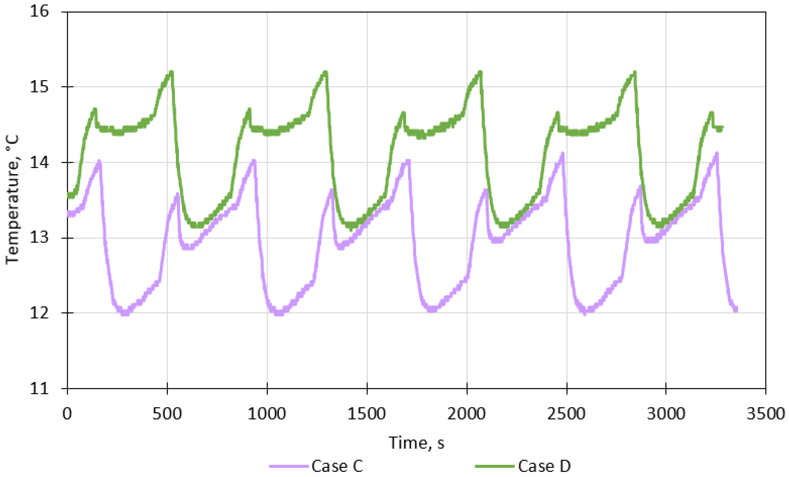
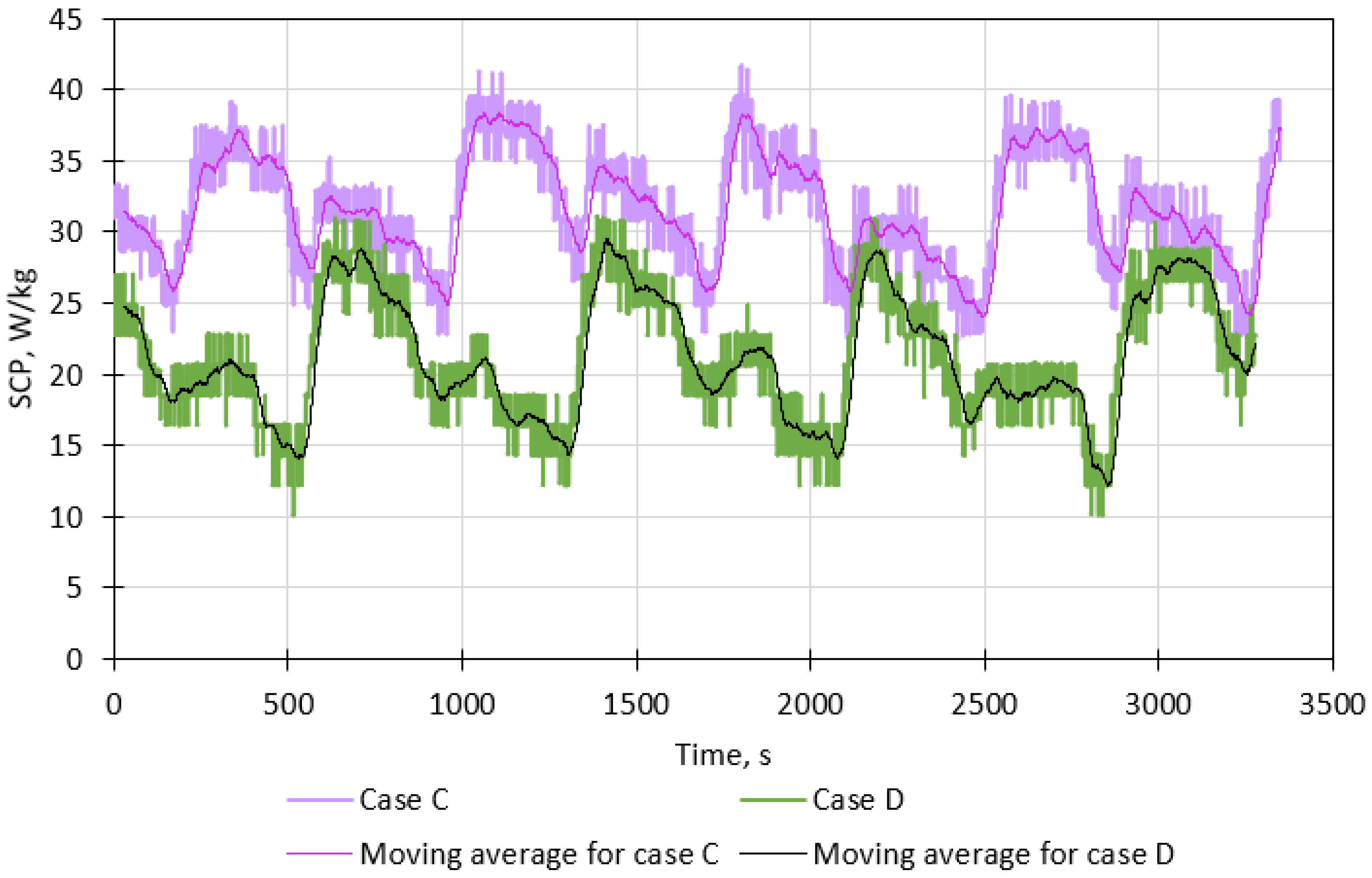
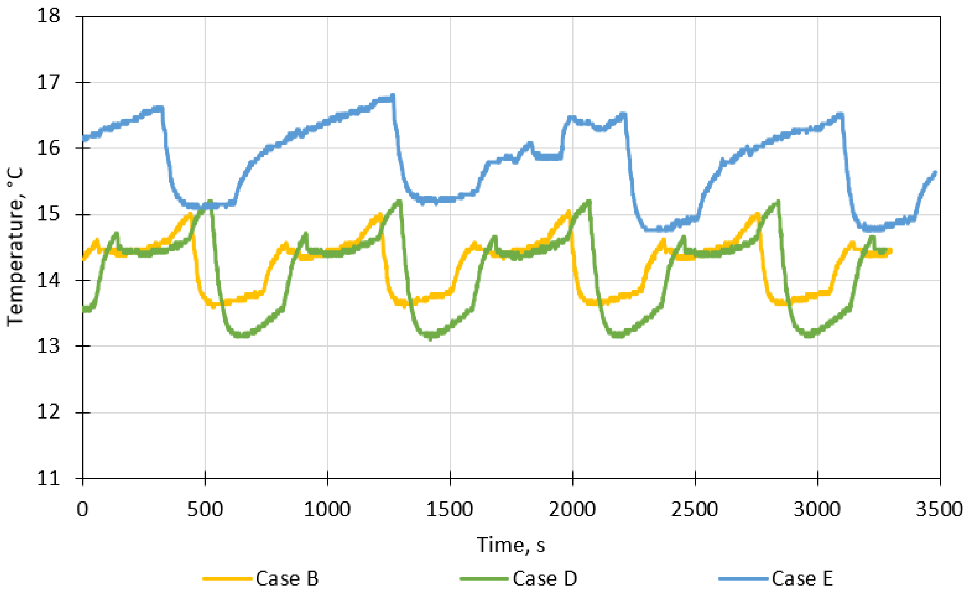
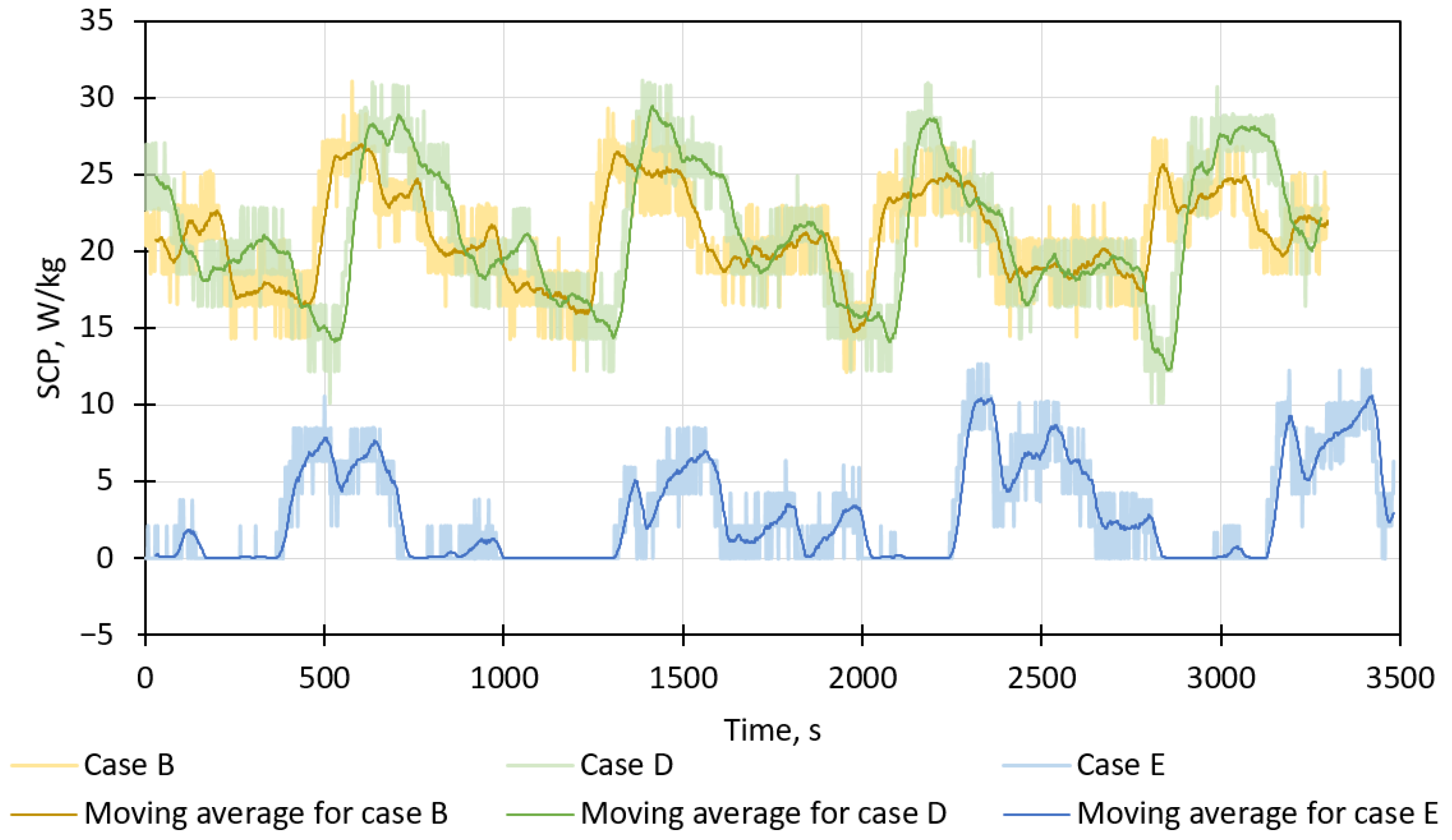
3.2. The Effect of the Number of Nozzles on Adsorption-Chiller Performance

The second goal of the research is to investigate how changing the number of nozzles will affect the operation of the system. Therefore, the operating parameters of the adsorption chiller with six or three type 2 nozzles are compared.
Figure 12 presents the cooling capacity of the adsorption chiller working with different numbers of nozzles and different water flow rates. As illustrated, reducing the number of nozzles from six (cases B and D) to three (case E) causes a significant decrease in the cooling capacity, even if the total water flow rate is maintained. A plausible explanation of this result is that spraying water using only three nozzles causes water droplets to fall on a smaller surface area of the heat exchanger, which hinders evaporation. The average cooling capacity for three nozzles and a water flow rate of 200 L/h is 29 W (standard deviation of 33 W).
The temperature inside the evaporator for different numbers of nozzles is shown in Figure 13. The temperature inside the evaporator is higher when three nozzles (case E) are used than when six nozzles (cases B and D) are used. The average evaporator temperature for case E is 15.78 °C (standard deviation of 0.60 °C), while for six nozzles (cases B and D), it is about 14 °C. A higher temperature in the evaporator in case E results in a higher temperature for the chilled water generated in the evaporator. Thus, reducing the number of nozzles is not advisable if low-temperature chilled water is required.
Figure 14 presents the SCP of the adsorption chiller working with various numbers of nozzles. The SCP changes are analogous to the cooling capacity, as the SCP is directly proportional to the cooling capacity and inversely proportional to the mass of the sorbent, which is 10 kg in this research.

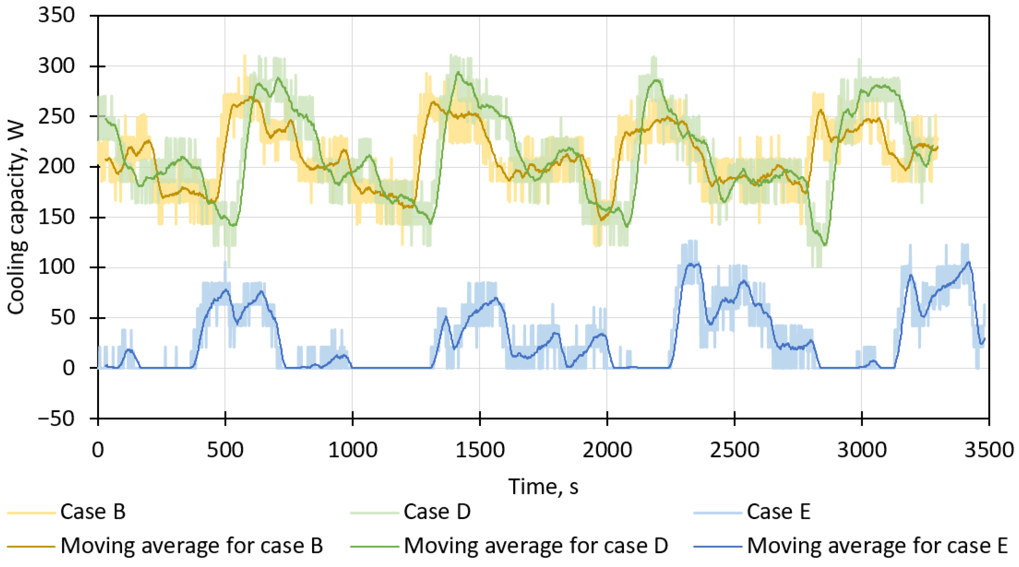
3.3. Summary of Results

The average values of the operating parameters of the investigated adsorption chiller are summarized in Table 5. The results indicate that the total flow rate of the water sprayed by the nozzles plays a minor role in the operation of the entire unit. However, as the water flow rate decreases, the operation of the unit is more unstable, which is evidenced by a higher standard deviation and is presented in the figures in the previous sections. On the other hand, the influence of the spray angle of the nozzles is more meaningful. The operating parameters of the chiller are better if the spray angle is 120° than if it is 90°. The number of nozzles has the greatest impact on chiller operation. Reducing the number of nozzles from six to three resulted in a drastic decrease in cooling capacity, SCP, and EER, as well as an increase in the average temperature in the evaporator and therefore an increase in the temperature of chilled water generated.

4. Conclusions

This paper presents the results of experimental research on the effect of the spray angle of nozzles and the number of nozzles in the evaporator on adsorption-chiller performance. Two types of nozzles were tested: the first type with a spray angle of 120° and the second type with a spray angle of 90°. Additionally, the number of nozzles was either six or three, and the total flow rate through the nozzles was either 400 L/h or 200 L/h.
It is found that nozzles with a higher spray angle are advisable to use because they ensure a greater cooling capacity (by about 50%), SCP (by about 50%), and EER (by about 48%). Furthermore, a greater spray angle results in lower pressure and temperature inside the evaporator, which translates into a lower temperature for the generated chilled water. The next finding of this study is that the water flow rate through the nozzles has a minor impact on the average values of the operating parameters of the adsorption chiller, but it causes the chiller to operate with slightly more fluctuations. The most important outcome of this research is that the number of nozzles plays the most relevant role in the evaporation process and affects the operating parameters for each component of an adsorption chiller. Reducing the number of nozzles from six to three results in a tenfold reduction in the EER, cooling capacity, and SCP.
The results presented in this paper give insight into the effect of nozzle configuration in the evaporator on an adsorption chiller’s performance. The addressed topic and the outcomes of this study are valuable contributions to the development of adsorption-chiller technology.

Author Contributions

Conceptualization, K.S., Ł.M. and W.K.; methodology, W.K. and K.S.; formal analysis, J.K. and E.R.; investigation, W.K. and J.K.; data curation, J.K. and W.K.; writing—original draft preparation, J.K. and E.R.; writing—review and editing, E.R., K.S., W.K. and W.N.; visualization, J.K. and E.R.; supervision, Ł.M., K.S. and W.N.; project administration, K.S. and A.G.; funding acquisition, Ł.M. All authors have read and agreed to the published version of the manuscript.

Funding

This research was funded by the Ministry of Science and Higher Education, Poland, AGH grant No. 16.16.210.476, and partly supported by the Excellence Initiative—Research University program of the AGH University of Krakow.

Data Availability Statement

Data is contained within the article.

Conflicts of Interest

Author Jakub Kozaczuk was employed by the company JWA Polska. The remaining authors declare that the research was conducted in the absence of any commercial or financial relationships that could be construed as a potential conflict of interest.

References

  1. International Energy Agency. The Future of Cooling. Available online: https://www.iea.org/reports/the-future-of-cooling (accessed on 10 November 2023).
  2. Bolaji, B.O.; Huan, Z. Ozone depletion and global warming: Case for the use of natural refrigerant—A review. Renew. Sustain. Energy Rev. 2013, 18, 49–54. [Google Scholar] [CrossRef]
  3. Chauhan, P.R.; Kaushik, S.C.; Tyagi, S.K. Current status and technological advancements in adsorption refrigeration systems: A review. Renew. Sustain. Energy Rev. 2022, 154, 111808. [Google Scholar] [CrossRef]
  4. Alsaman, A.S.; Askalany, A.A.; Harby, K.; Ahmed, M.S. A state of the art of hybrid adsorption desalination–cooling systems. Renew. Sustain. Energy Rev. 2016, 58, 692–703. [Google Scholar] [CrossRef]
  5. Kuczyńska, A.; Szaflik, W. Absorption and adsorption chillers applied to air conditioning systems. Arch. Thermodyn. 2010, 31, 77–94. [Google Scholar] [CrossRef]
  6. Akhtar, S.; Khan, T.S.; Ilyas, S.; Alshehhi, M.S. Feasibility and Basic Design of Solar Integrated Absorption Refrigeration for an Industry. Energy Procedia 2015, 75, 508–513. [Google Scholar] [CrossRef]
  7. Sztekler, K.; Kalawa, W.; Nowak, W.; Mika, L.; Gradziel, S.; Krzywanski, J.; Radomska, E. Experimental study of three-bed adsorption chiller with desalination function. Energies 2020, 13, 5827. [Google Scholar] [CrossRef]
  8. Sztekler, K.; Kalawa, W.; Mika, L.; Lis, L.; Radomska, E.; Nowak, W. The effects of using steam to preheat the beds of an adsorption chiller with desalination function. Energies 2021, 14, 6454. [Google Scholar] [CrossRef]
  9. Iguchi, K.; Nakayama, M.; Akisawa, A. Method for estimating optimum cycle time based on adsorption chiller parameters. Int. J. Refrig. 2019, 105, 66–71. [Google Scholar] [CrossRef]
  10. Shmroukh, A.N.; Ali, A.H.H.; Ookawara, S. Adsorption working pairs for adsorption cooling chillers: A review based on adsorption capacity and environmental impact. Renew. Sustain. Energy Rev. 2015, 50, 445–456. [Google Scholar] [CrossRef]
  11. Thimmaiah, P.C.; Sharafian, A.; Rouhani, M.; Huttema, W.; Bahrami, M. Evaluation of low-pressure flooded evaporator performance for adsorption chillers. Energy 2017, 122, 144–158. [Google Scholar] [CrossRef]
  12. Kalawa, W.; Grabowska, K.; Sztekler, K.; Krzywański, J.; Sosnowski, M.; Stefański, S.; Siwek, T.; Nowak, W. Progress in design of adsorption refrigeration systems. Evaporators. EPJ Web Conf. 2019, 213, 02035. [Google Scholar] [CrossRef]
  13. Toppi, T.; Villa, T.; Vasta, S.; Mittelbach, W.; Freni, A. Testing of a Falling-Film Evaporator for Adsorption Chillers. Energies 2022, 15, 1709. [Google Scholar] [CrossRef]
  14. Woo, S.Y.; Lee, H.S.; Ji, H.; Moon, D.S.; Kim, Y.D. Silica gel-based adsorption cooling cum desalination system: Focus on brine salinity, operating pressure, and its effect on performance. Desalination 2019, 467, 136–146. [Google Scholar] [CrossRef]
  15. Spray Nozzles. Available online: https://www.spray-nozzle.co.uk/spray-nozzles (accessed on 12 November 2023).
  16. Cheng, W.L.; Zhang, W.W.; Chen, H.; Hu, L. Spray cooling and flash evaporation cooling: The current development and application. Renew. Sustain. Energy Rev. 2016, 55, 614–628. [Google Scholar] [CrossRef]
  17. Balaji, D. Experimental study on the effect of feed water nozzles on non-equilibrium temperature difference and flash evaporation in a single-stage evaporator and an investigation of effect of process parameters on the liquid flashing in a LTTD desalination process. Desalin. Water Treat. 2016, 57, 27152–27168. [Google Scholar] [CrossRef]
  18. Chien, L.H.; Xu, J.J.; Yang, T.F.; Yan, W.M. Experimental study on water spray uniformity in an evaporative condenser of a water chiller. Case Stud. Therm. Eng. 2019, 15, 100512. [Google Scholar] [CrossRef]
  19. Fathinia, F.; Khiadani, M.; Al-Abdeli, Y.M.; Shafieian, A. Performance improvement of spray flash evaporation desalination systems using multiple nozzle arrangement. Appl. Therm. Eng. 2019, 163, 114385. [Google Scholar] [CrossRef]
  20. Zhang, T.; Mo, Z.; Xu, X.; Liu, X.; Chen, H.; Han, Z.; Yan, Y.; Jin, Y. Advanced Study of Spray Cooling: From Theories to Applications. Energies 2022, 15, 9219. [Google Scholar] [CrossRef]
  21. Fathinia, F.; Khiadani, M.; Al-Abdeli, Y.M. Experimental and mathematical investigations of spray angle and droplet sizes of a flash evaporation desalination system. Powder Technol. 2019, 355, 542–551. [Google Scholar] [CrossRef]
  22. Chen, Q.; Thu, K.; Bui, T.D.; Li, Y.; Ng, K.C.; Chua, K.J. Development of a model for spray evaporation based on droplet analysis. Desalination 2016, 399, 69–77. [Google Scholar] [CrossRef]
  23. Chang, T.B.; Yu, L.Y. Optimal nozzle spray cone angle for triangular-pitch shell-and-tube interior spray evaporator. Int. J. Heat Mass Transf. 2015, 85, 463–472. [Google Scholar] [CrossRef]
  24. Sztekler, K.; Kalawa, W.; Nowak, W.; Mika, Ł.; Krzywański, J.; Grabowska, K.; Sosnowski, M.; Alharbi, A.A. Performance Evaluation of a Single-Stage Two-Bed Adsorption Chiller With Desalination Function. J. Energy Resour. Technol. 2021, 143, 082101. [Google Scholar] [CrossRef]
  25. Taylor, J.R. An Introduction to Error Analysis. In The Study of Uncertainties in Physical Measurements, 2nd ed.; University Science Books: Sausalito, CA, USA, 1997. [Google Scholar]
  26. Liu, X.; Yu, L.; Zhao, L.; Hua, Z.; Xue, H. A comprehensive simulation analysis to optimize the performance of spray evaporator on treating concentrated brine. Desalination 2023, 548, 116292. [Google Scholar] [CrossRef]
  27. Dai, Z.; Zhang, Y.; Wang, S.; Nawaz, K.; Jacobi, A. Falling-film heat exchangers used in desalination systems: A review. Int. J. Heat Mass Transf. 2022, 185, 122407. [Google Scholar] [CrossRef]
Figure 1. A photograph of the investigated adsorption chiller.
Energies 17 01181 g001
Figure 2. A simplified diagram of the adsorption chiller working in chilling mode.
Energies 17 01181 g002
Figure 3. Schematic diagram of the evaporator: 1—supply-water inlet to the nozzles; 2—water vapor flowing to the bed; 3—condensate from the condenser.
Energies 17 01181 g003
Figure 4. (a) Cross-section of the evaporator: 1—manifold; 2—nozzle; 3—coil with chilled water; (b) side view of the evaporator (dimensions are in mm).
Energies 17 01181 g004
Figure 5. Nozzles in the evaporator: (a) Type 1 (spray angle of 120°); (b) Type 2 (spray angle of 90°).
Energies 17 01181 g005
Figure 6. Cooling capacity for a total water flow rate of 400 L/h with six nozzles.
Energies 17 01181 g006
Figure 7. Cooling capacity for a total water flow rate of 200 L/h with six nozzles.
Energies 17 01181 g007
Figure 8. The temperature inside the evaporator for a total water flow rate of 400 L/h with six nozzles.
Energies 17 01181 g008
Figure 9. The temperature inside the evaporator for a total water flow rate of 200 L/h with six nozzles.
Energies 17 01181 g009
Figure 10. Specific cooling power (SCP) for a total water flow rate of 400 L/h with six nozzles.
Energies 17 01181 g010
Figure 11. Specific cooling power (SCP) for a total water flow rate of 200 L/h with six nozzles.
Energies 17 01181 g011
Figure 12. Cooling capacity for different numbers of nozzles and water flow rates.
Energies 17 01181 g012
Figure 13. The temperature inside the evaporator for different numbers of nozzles and water flow rates.
Energies 17 01181 g013
Figure 14. Specific cooling power (SCP) for different numbers of nozzles and water flow rates.
Energies 17 01181 g014
Table 1. Basic operating parameters of the investigated adsorption chiller.
ParameterValueUnit
Heating-water temperature80°C
Cooling-water temperature at the inlet to the beds 20°C
Cooling-water temperature at the inlet to the condenser 18°C
Supply-water temperature at the inlet to the evaporator15°C
Table 2. Measured parameters and measuring devices.
ParameterMeasuring Device Range of the Measuring Device Accuracy of the Measuring Device
Condenser pressure (PT-10)Pressure transducer
Simex DMK-457, Simex, Gdańsk, Poland
From 0 to 99 kPa±0.5%
Cooling-water temperature—inlet to the condenser (TT-03)Pt-1000 sensor
JUMO 902020/15, JUMO Polska, Wrocław, Poland
From −80 to 150 °C±0.1 °C
Cooling-water temperature—outlet from the condenser (TT-02)Pt-1000 sensorFrom −80 to 150 °C±0.1 °C
Condenser cooling-water flow rate (FT-02)Electromagnetic flow meter
KHRONE Optiflux 4050C, Khrone Polska, Gdańsk, Poland
From 1 to 100 L/min±0.5%
Evaporator pressure (PT-04)Pressure transducerFrom 0 to 99 kPa±0.5%
Evaporator temperature (TT-01)
Pressure inside bed 1 (PT-05)Pressure transducerFrom 0 to 99 kPa±0.5%
Pressure inside bed 2 (PT-06)Pressure transducerFrom 0 to 99 kPa±0.5%
Chilled-water temperature—inlet to the evaporator (TT-06)Pt-1000 sensorFrom −80 to 150 °C±0.1 °C
Chilled-water temperature—outlet from the evaporator (TT-07)Pt-1000 sensorFrom −80 to 150 °C±0.1 °C
Chilled-water flow rate (FT-03)Electromagnetic flow meterFrom 1 to 100 L/min±0.5%
Heating-water flow rate Electromagnetic flow meterFrom 1 to 100 L/min±0.5%
Heating-water temperature—inlet to the bed (B2-01 and B3-01)Pt-1000 sensorFrom −80 to 150 °C±0.1 °C
Heating-water temperature—outlet from the bed (TT-04)Pt-1000 sensorFrom −80 to 150 °C±0.1 °C
Table 3. Flow rate of water through the nozzle as a function of pressure.
Pressure, BarWater Flow Rate—Type 1 Nozzles, L/hWater Flow Rate—Type 2 Nozzles, L/h
0.554.034.2
1.064.245.6
2.0108.060.0
3.0132.670.8
5.0153.086.4
Table 4. The conducted experiments and their operating parameters.
ExperimentNumber of NozzlesType of NozzleSpray Angle, °Total Water Flow Rate, L/hWater Flow Rate through One Nozzle, L/h
A6112040066.7
B629040066.7
C6112020033.3
D629020033.3
E329020066.7
Table 5. Average values of the operating parameters of the investigated adsorption chiller for different nozzle configurations.
ParameterUnitA *B *C *D *E *
EER-0.1670.1100.1670.1150.022
Cooling capacityW31621031921129
SCPW/kg31.621.031.921.12.9
Condenser pressurekPa5.716.095.806.276.39
Evaporator pressurekPa1.571.701.551.681.98
Bed pressure during adsorptionkPa1.661.811.651.822.35
Bed pressure during desorptionkPa5.806.175.906.356.47
Evaporator temperature°C13.0614.2412.9114.1215.78
Chilled-water temperature at the inlet to the evaporator°C15.2215.6015.1715.5915.81
Chilled-water temperature at the outlet from the evaporator°C14.4715.1014.4215.0915.76
* A—six type 1 nozzles, water flow rate of 400 L/h; B—six type 2 nozzles, water flow rate of 400 L/h; C—six type 1 nozzles, water flow rate of 200 L/h; D—six type 2 nozzles, water flow rate of 200 L/h; E—three type 2 nozzles, water flow rate of 200 L/h.
Disclaimer/Publisher’s Note: The statements, opinions and data contained in all publications are solely those of the individual author(s) and contributor(s) and not of MDPI and/or the editor(s). MDPI and/or the editor(s) disclaim responsibility for any injury to people or property resulting from any ideas, methods, instructions or products referred to in the content.

