Article

Coordinated Control of the Hybrid Electric Ship Power-Based Batteries/Supercapacitors/Variable Speed Diesel Generator

by
Mamadou Baïlo Camara
* and
Brayima Dakyo
*
GREAH-Laboratory, Faculty of Technical Sciences, University of Le Havre Normandie, 75 Rue Bellot, 76600 Le Havre, France
*
Authors to whom correspondence should be addressed.
Energies 2023, 16(18), 6666; https://doi.org/10.3390/en16186666
Submission received: 14 July 2023 / Revised: 9 September 2023 / Accepted: 11 September 2023 / Published: 17 September 2023
(This article belongs to the Special Issue Electric, Hybrid and Fuel Cell Vehicles for Sustainable Mobility)

Abstract

:
A Hybrid Electric Ship (HES) is investigated in this work to improve its dynamic response to sudden power demand changes. The HES system is based on a Variable-Speed Diesel Generator (VSDG) used for long-term energy supply, with Two Energy Storage Systems (TESSs) using Batteries and supercapacitors for transient power supply. The TESS mitigates the power demand fluctuations and reduces its impact on VSDG, which is linked to a DC-bus through a controlled rectifier. Batteries and Supercapacitors (SCs) are connected in a DC-bus using the bidirectional DC/DC converters to manage the transient and fluctuating components. Two thrusters (one in the front and the second in the back of the Ship) are considered for the propulsion system. The HES power demand includes the requirement of the thrusters and embedded power consumers (elevator, package lifting, air conditioning, onboard electronics devices, etc.). The highlight of this paper is based on the HES fast response improvement in sudden power demand situations via TESS-based batteries and supercapacitors. The other highlight concerns the SCs’ electrothermal modeling using an extension of the SCs’ current ripples’ frequency range (0 to 1 kHz), considering parameter evolution according to using the temperature and current waveform. This energy management-based dynamic power component separation method is tested via simulations using a variable operating temperature scenario.

1. Introduction

In conventional diesel Ships, constant-speed diesel engines are frequently used for cost and simplicity motives. Therefore, the engine for direct propulsion or the engine and generator in the case of electric propulsion needs oversizing; if not, the torque and/or voltage dip at a sudden power demand surge is unavoidable. A similar issue is described in Ref. [1], where the minimum voltage reached by the DC-bus is 320 V compared to the set point of 400 V. Therefore, the operation of sensitive power consumers such as multimedia and other electronic devices can be affected by the DC-bus voltage variations. If the diesel engine operates at a constant speed without the assistance of batteries/supercapacitors, it generally does not operate at the optimal point (minimal fuel consumption), particularly in light-load situations. To optimize fuel consumption through diesel-engine optimal operation points tracking, the speed of the diesel engine needs adjustment according to the Hybrid Electric Ship (HES) power demand. Similar issues are presented in Refs. [2,3,4], where the fuel consumption performances of Variable-Speed Diesel Generators (VSDG) are compared to that of constant-speed diesel generators. Due to the slow-acting nature of a diesel engine coupled to a generator, the produced power cannot react to the fast power demand. In this situation, the DC-bus voltage cannot be kept constant through the control. In this case, the power required during the fast-load demand is not obtainable from the diesel generator because the engine speed cannot react fast due to the mechanical time constant. Then, the fast variations of the power demand degrade the diesel generator’s energetic performance.
To solve this issue, a diesel generator can be assisted in transient operations by coordinated power control based on the fast-acting capability of energy storage units. A similar technique is presented in Ref. [5], where the direct coupling of Supercapacitors (SCs) and batteries is considered without the separation of dynamic act capability between the SCs and batteries. According to the information in the literature, using TESS-based supercapacitors–batteries is proposed to attenuate the power demand variation effect for VSDG implemented in an HES. Batteries and SCs are coupled in a DC-bus via two bidirectional DC/DC converters. This option allows the control of the transient powers assigned to the batteries and SCs considering their dynamic action capability. Using supercapacitors–batteries to assist VSDG in transient situations allows one to attenuate the power variation impact for the diesel generator and consolidate the HES energetic performances [6,7]. TESS-based supercapacitors–batteries are used because energy storage via batteries or SCs only is limited in cycle life for existing batteries or in terms of energy for SCs. Fast variations in the power demand impose very frequent and partial charge and discharge cycles on the batteries. So, the rapid aging of batteries is a key challenge today for electric vehicles, particularly for HES applications. Table 1 summarizes the characteristics of the batteries and supercapacitors used in an HES. The TESS concept allows us to exploit the complementary performances of the batteries and SCs. The highlight of this work is based on an HES fast-acting improvement during sudden power demand changes using TESS-based batteries–supercapacitors. The highlight of this work compared to the literature is focused on the electric Energy Management (EM) method, which considers SCs–batteries’ parameter dependency on temperature and their fast-acting capability during transient operations of the HES. An additional highlight of the paper concerns electrothermal modeling of the SCs with the current ripples’ frequency range extending from 0 to 1 kHz.
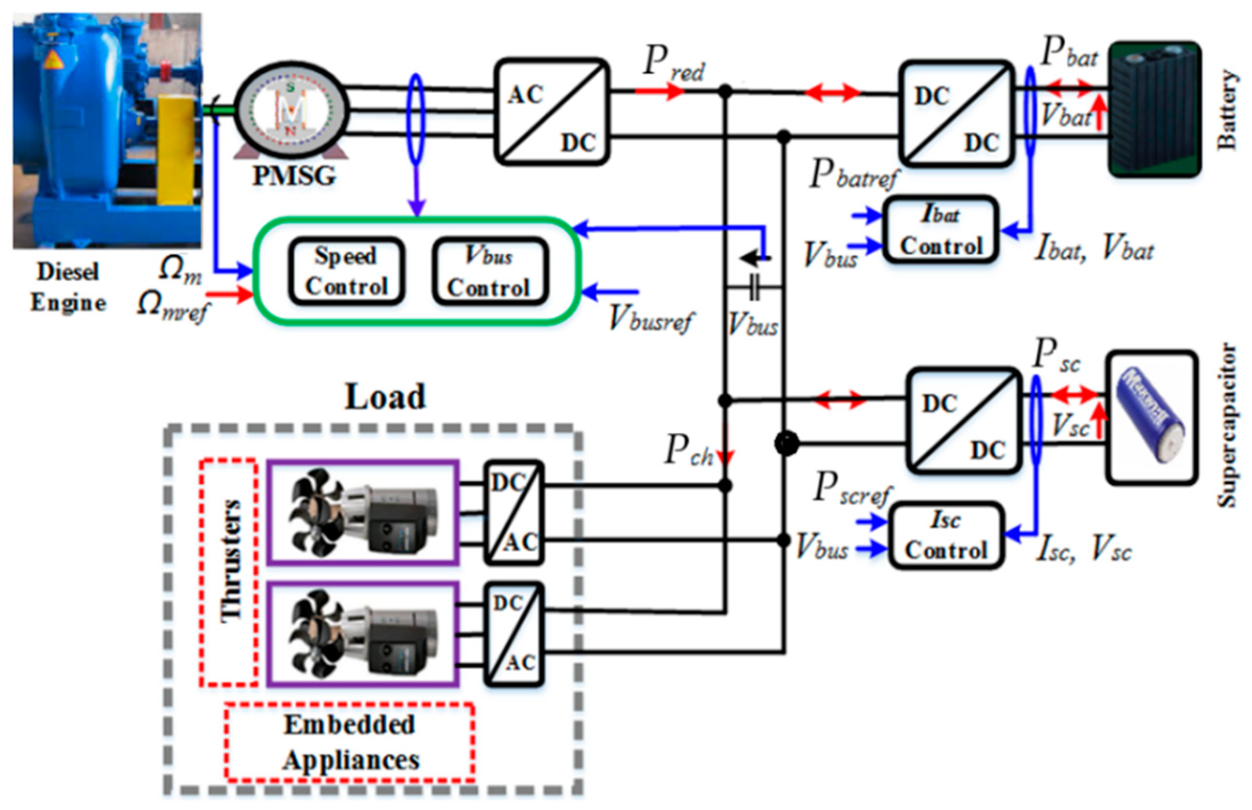
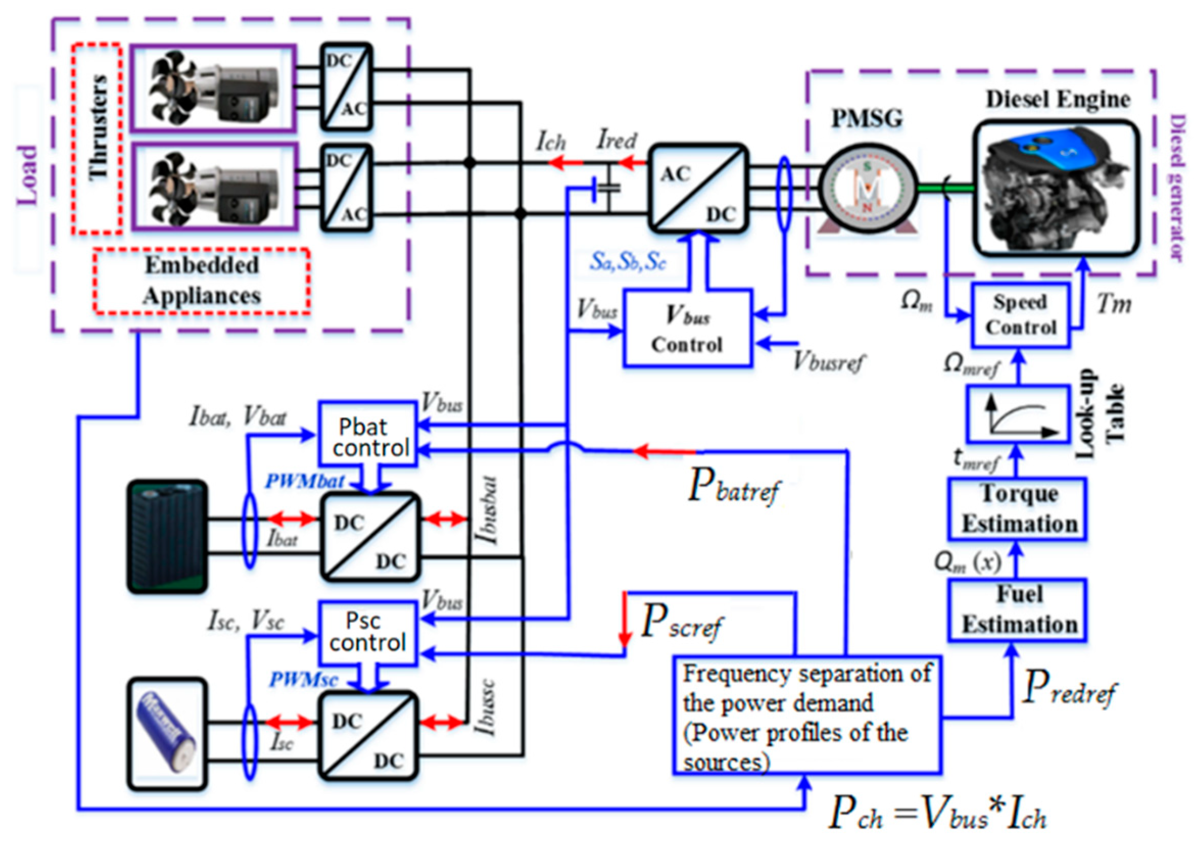
Coordinated control of the transient power use Dynamic Components Separation Concept (DCSC), with an interesting flexibility compared to the classic power control-based time domain, was described in Refs. [8,9,10,11,12,13,14]. The DCSC allows for coordinated transient power control without previous knowledge of the HES power demand profile (database), which is interesting when facing load demand changes. DCSC allows batteries–supercapacitors’ optimal dimensioning to be adapted to the dynamic power demand of the HES. One type of an HES is presented in Figure 1, and its electric configuration is presented in Figure 2, where the load presents the total power needed by the thrusters and onboard equipment. A diesel generator is interfaced in the DC-bus through a controlled AC/DC converter to control the voltage in the DC-bus. Battery and SC modules are interfaced in the DC-bus using two DC/DC converters to manage the transient and dynamic components of the load’s power demand.
This paper is structured as follows: Batteries and SCs models are exposed in Section 2; the coordinated power control-based DCSC is presented in Section 3; hybrid electric ship behavior simulations are given in Section 4; and conclusions and remarks are given in Section 5.

2. Energy Storage Systems Behavior Modeling

2.1. LiFePO4-Battery Modeling

A Lithium-Iron-Phosphate (LiFePO4) battery model is proposed in this subsection. LiFePO4 battery technology presents a good compromise of the cost and required energetic performances [15,16,17,18,19,20,21]. The proposed model of the batteries is extracted from the LFP-100 Ah/3.2 V battery’s cell characterization using the method described in [16,21]. The resulting models of the resistance and capacity of the batteries obtained from 4800 cycles of charge/discharge tests based on four battery cells are given in Equation (1), where T represents the operating temperature in [°C] and Fr is the ripples’ frequency of the current of the battery in [Hz]. These models enable us to describe the degradation of the resistance and capacity when the batteries are submitted to the temperature and current waveform constraints at the same time.
R Cell F r , T = 1 1000 R α + R β + R γ R α = k 0 + k 10 F r + k 01 T + k 20 F r 2 R β = k 11 F r T + k 02 T 2 + k 30 F r 3 R γ = k 21 F r 2 T + k 12 F r T 2 Q cell _ ch F r , T Q cell _ di F r , T = Q α + Q β Q α = q 0 + q 10 F r + q 01 T + q 20 F r 2 Q β = q 11 F r T + q 02 T 2
The coefficients of Equation (1) are specified as follows: k0 = 2.26; k10 = 0.45; k01 = −0.56; k20 = −0.47; k11 = −0.15; k02 = 0.31; k30 = 0.14; k21 = 0.15; k12 = −4.14 × 10⁻²; q0 = 84; q10 = 1.01; q01 = 1.50; q20 = −0.16; q11 = −0.22; q02 = −0.015.
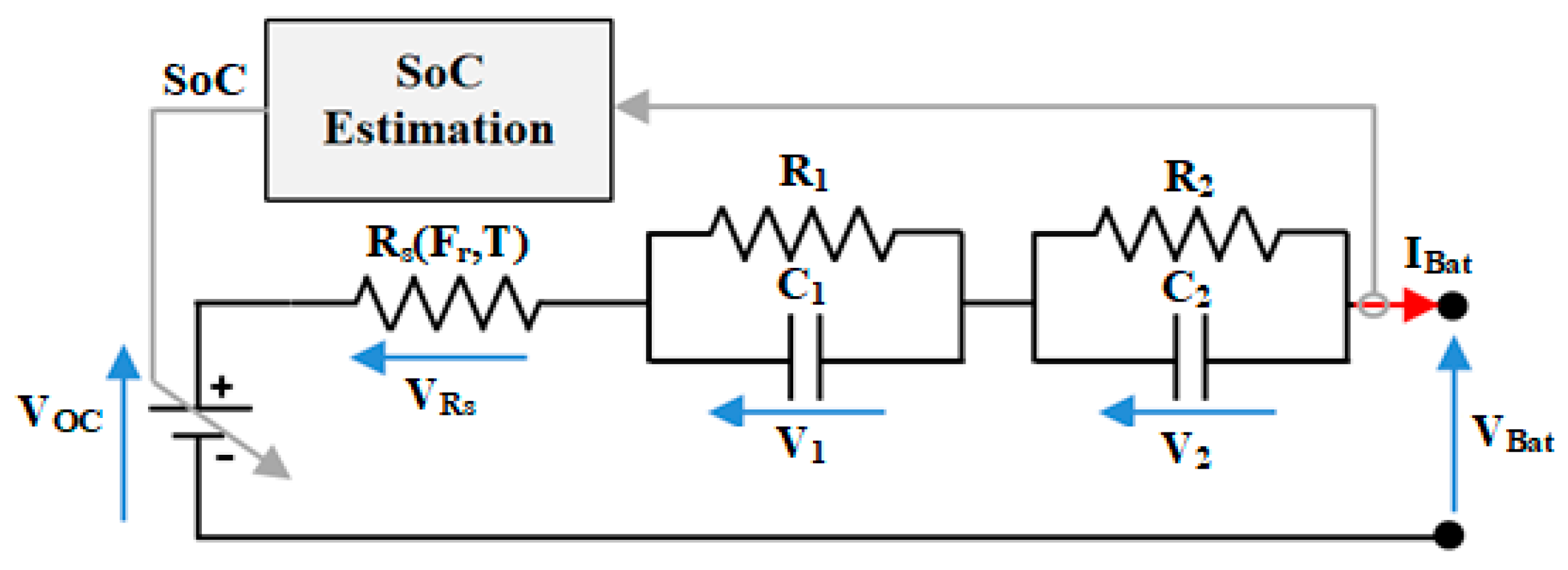
The electric behavior model of the battery module is shown in Figure 3, where the open circuit voltage Voc depends on the state of charge (SoC) and the sign of the current. The series resistance RS (Fr,T) depends on the temperature and frequency of the current ripples. The two time constants (R1*C1 and R2*C2) are supposedly constant.
{ S o C = { S o C ( t 0 ) + t 0 t ( I B a t 3600     Q c e l l _ c h ( F r , T ) ) · d t f o r I B a t < 0 S o C ( t 0 ) t 0 t ( I B a t 3600     Q c e l l _ d i ( F r , T ) ) · d t f o r I B a t > 0 d d t [ V 1 V 2 ] = [ 1 R 1 C 1 0 0 1 R 2 C 2 ] [ V 1 V 2 ] + [ 1 C 1 0 1 C 2 0 ] [ I B a t 0 ] R s ( F r , T ) = N S _ B a t N p _ B a t R C e l l ( F r , T ) + ( N S _ B a t 1 ) N p _ B a t R b w i V o c ( S o C ) = { c 5 S o C 5 + c 4 S o C 4 c 3 S o C 3 + c 2 S o C 2 + c 1 S o C + c 0         f o r         I B a t < 0 d 5 S o C 5 + d 4 S o C 4 d 3 S o C 3 + d 2 S o C 2 d 1 S o C + d 0         f o r         I B a t > 0 V B a t = N S _ B a t V o c ( S o C ) + ( N S _ B a t N p _ B a t ) ( R s I B a t + V 1 + V 2 )
Equation (2) presents the mathematical model of the LiFePO4 battery module, where RCell(Fr,T) is the resistance of the battery’s cell presented previously; NS_Bat represents the number of batteries in series; NP_Bat is the number of sub-modules in parallel. The parameters of open circuit voltage VOC(SoC) model-based battery charge (IBat < 0)/discharge (IBat > 0) are given as c0 = 0.90; c1 = 4.80; c2 = 33; c3 = 140; c4 = 179; c5 = 74; d0 = 1; d1 = 0.70; d2 = 42; d3 = 132; d4 = 15; d5 = 62. This model enables us to describe the LiFePO4 batteries’ behavior when they are submitted to electrical and thermal constraints at the same time. The parameters used in the battery module are presented in Table 2.
The proposed electrical model of the batteries is an improvement on the classical constant parameter model presented in Ref. [21]. It results from a simplification of the global model presented in Ref. [16] to reduce the complexity of the model and the computing time, which is necessary for good energy management. In other words, it considers variations in the series resistance and capacitance according to electrical and thermal operating conditions. The parameters of parallel RC circuits are assumed to remain constant.

2.2. Supercapacitor Modeling

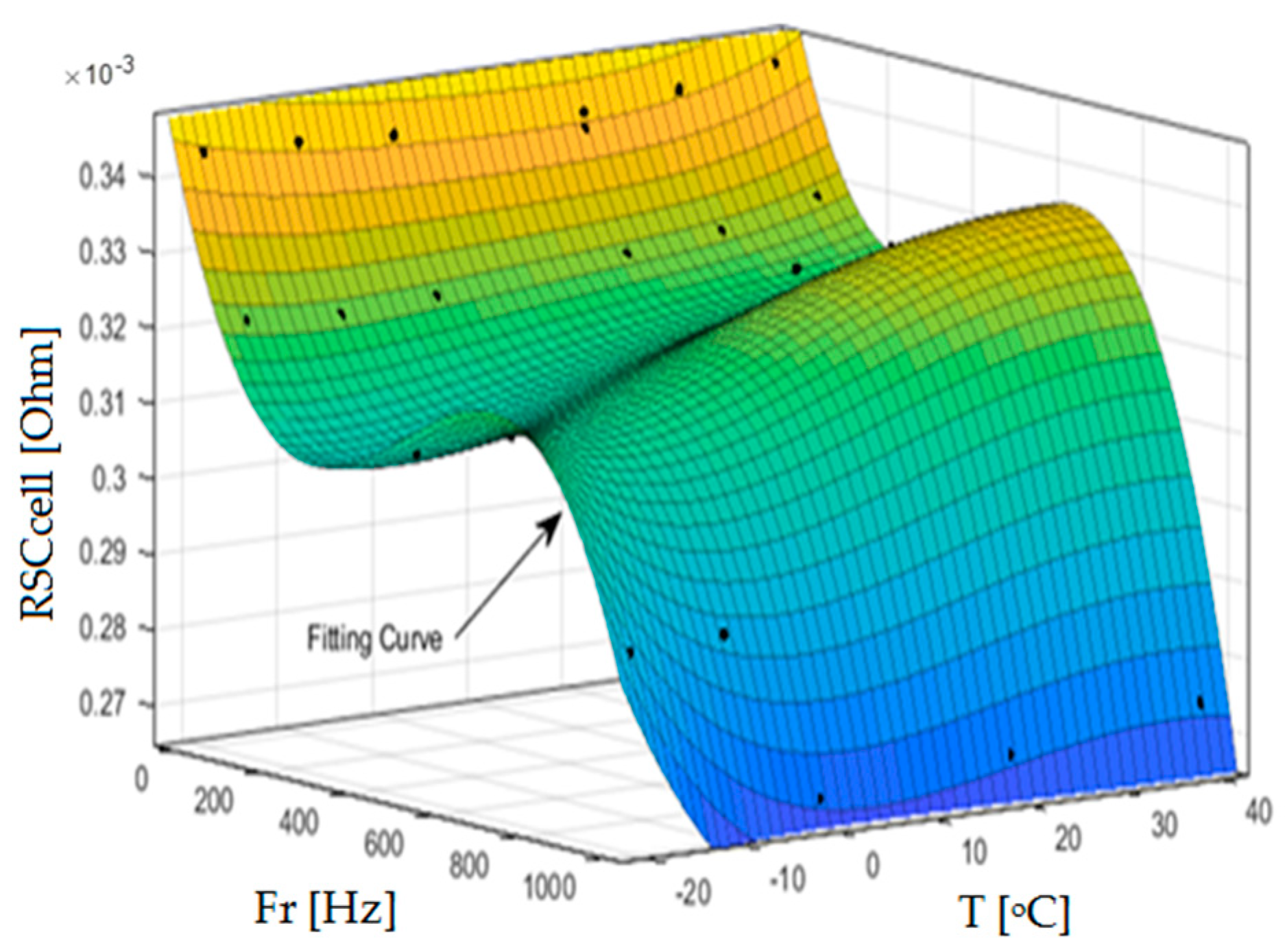
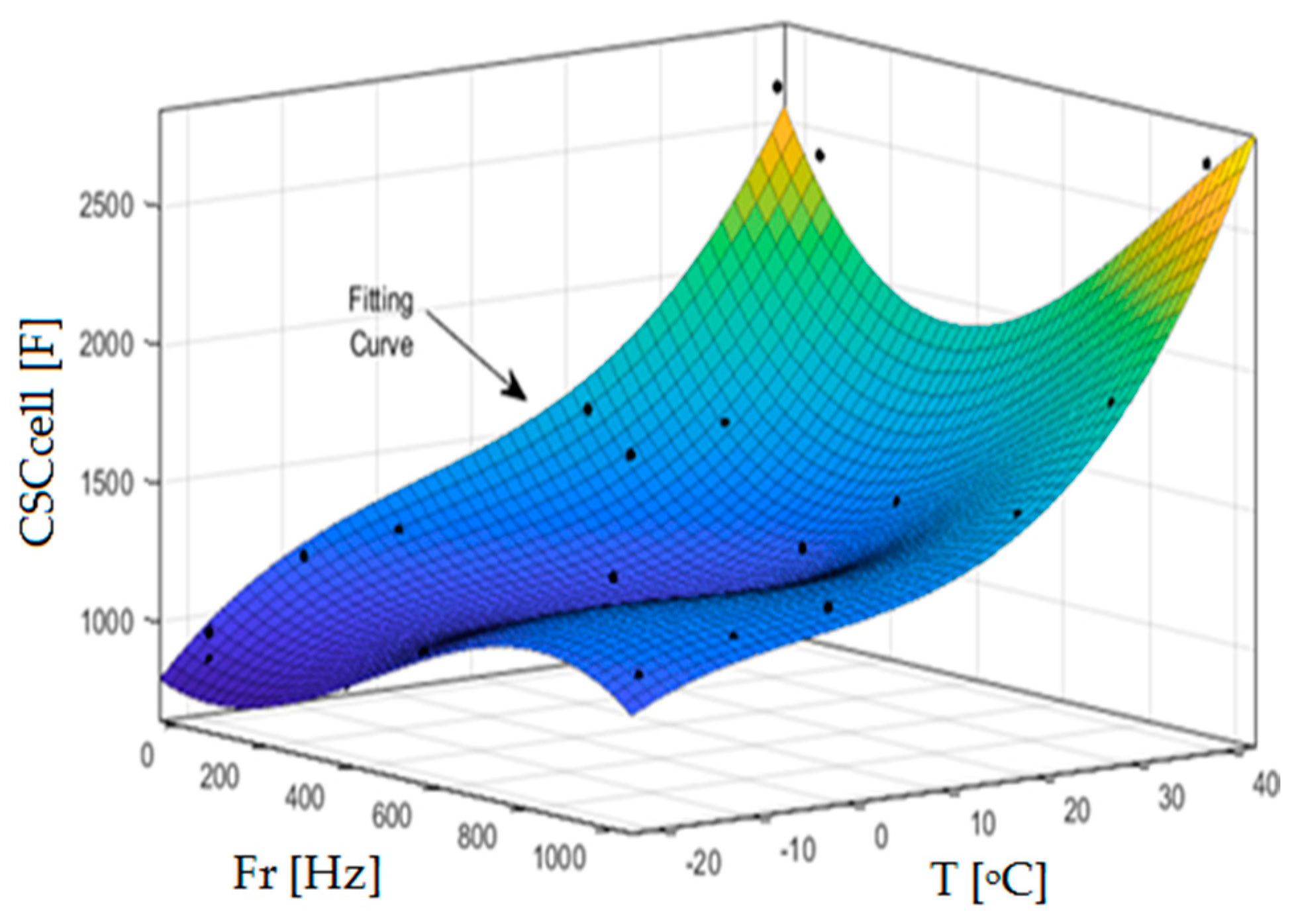
Supercapacitor (SC) modeling is performed by charge/discharge tests using fluctuating DC current waveforms with different operating temperatures. Various technologies and models of the SCs are proposed in the literature [22,23,24,25,26,27,28], but these models are usually limited due to the current and temperature changes. To consider these constraints, SC characterization is proposed to assess the degradation of the SCs’ capacitance and resistance using the frequency of the DC current ripples and the operating temperature to establish the SCs’ behavior model-based temperature and current waveforms. The SC characterization method is described in [26,27]. The degradation of the SCs’ resistance and capacitance according to electrothermal constraints is presented in Figure 4 and Figure 5, where T is the temperature and Fr is the frequency of the SCs’ current ripples. The resistance and capacitance models from the MATLAB curve-fitting Toolbox are presented in Equation (3), where T presents the temperature in [°C] and Fr is the supercapacitor’s current ripple frequency in [Hz].
R Sccell F r , T = 1 1000 R A + R B + R C R A = b 0 b 1 F r b 2 T + b 3 F r 2 + b 4 F r T + b 5 T 2 R B = b 6 F r 3 b 7 F r 2 T b 8 F r T 2 R C = b 9 T 3 b 10 F r 3 T + b 11 F r 2 T 2 b 12 F r T 3 + b 13 T 4 C Sccell F r , T = C A + C B C A = α 0 α 1 F r + α 2 T + α 3 F r 2 α 4 F r T α 5 T 2 C B = α 6 F r 3 + α 7 F r 2 T + α 8 F r T 2 + α 9 T 3
The coefficients of Equation (3) are as follows: b0 = 339.90; b1 = 2.28 × 10⁻¹; b2 = 6.22 × 10⁻²; b3 = 5.62 × 10⁻⁴; b4 = 1.62 × 10⁻³; b5 = 2.67 × 10⁻³; b6 = 4.05 × 10⁻⁷; b7 = 5.29 × 10⁻⁸; b8 = 1.54 × 10⁻⁵; b9 = 7.91 × 10⁻⁵; b10 = 1.76 × 10⁻⁹; b11 = 4.29 × 10⁻⁸; b12 = 5.55 × 10⁻⁷; b13 = 3.22 × 10⁻⁶; α0 = 124; α1 = 1.63; α2 = 10.46; α3 = 3.95 × 10⁻³; α4 = 0.046; α5 = 0.153; α6 = 2.225 × 10⁻⁶; α7 = 4.079 × 10⁻⁵; α8 = 2.984 × 10⁻⁴; α9 = 1.233 × 10⁻².
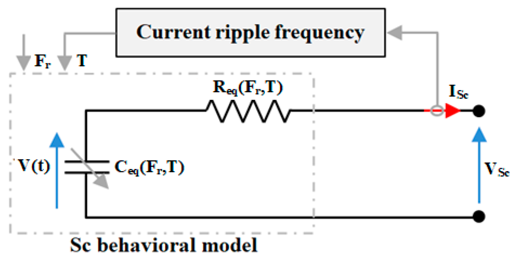
The resistance of the SC cell RSCcell (Fr,T) decreases as the frequency in the supercapacitor’s current increases. The capacitance of the cell CSCcell (Fr,T) increases as the frequency and temperature increase. The resulting model of the supercapacitor module is shown in Figure 6, where Req (Fr,T) is an equivalent series resistance and Ceq (Fr,T) is an equivalent capacitance, which depends on the temperature and frequency as illustrated in Equations (3) and (4). The mathematical model of the SC module is presented in Equation (4), where NS_SC is the number of SC cells in series and NP_SC is the number of SC sub-modules in parallel; Rwi is the wiring resistance of one cell and VSC0 is the initial voltage of the cell. Compared to the literature information, this model considers the frequency of current ripples and temperature changes, which are known to be major aging factors of SCs in real applications. The parameters of the SC module used are presented in Table 3.
V S C = N s _ S C V S C 0 0 t I S c C eq F r , T d t R eq F r , T I S c C eq F r , T = N p S C N s S C C S C c e l l ( F r , T ) R e q F r , T = N S _ S C N p _ S C R S C c e l l ( F r , T ) + N S _ S C 1 N p _ S C R w i
The electrical model of the supercapacitors proposed in this paper is an improvement of the constant-parameters model described in Ref. [21] and the low-frequency range (0 to 0.5 Hz) model presented in Ref. [26]. The improvement concerns the extension of the frequency range (0 to 1 kHz) of the current ripples while considering parameter evolution according to the temperature and current waveform used.

3. Coordinated Power Control of the Hybrid Electric Ship

3.1. Power Profiles of the Supercapacitors, Batteries, and Variable-Speed Diesel Generator

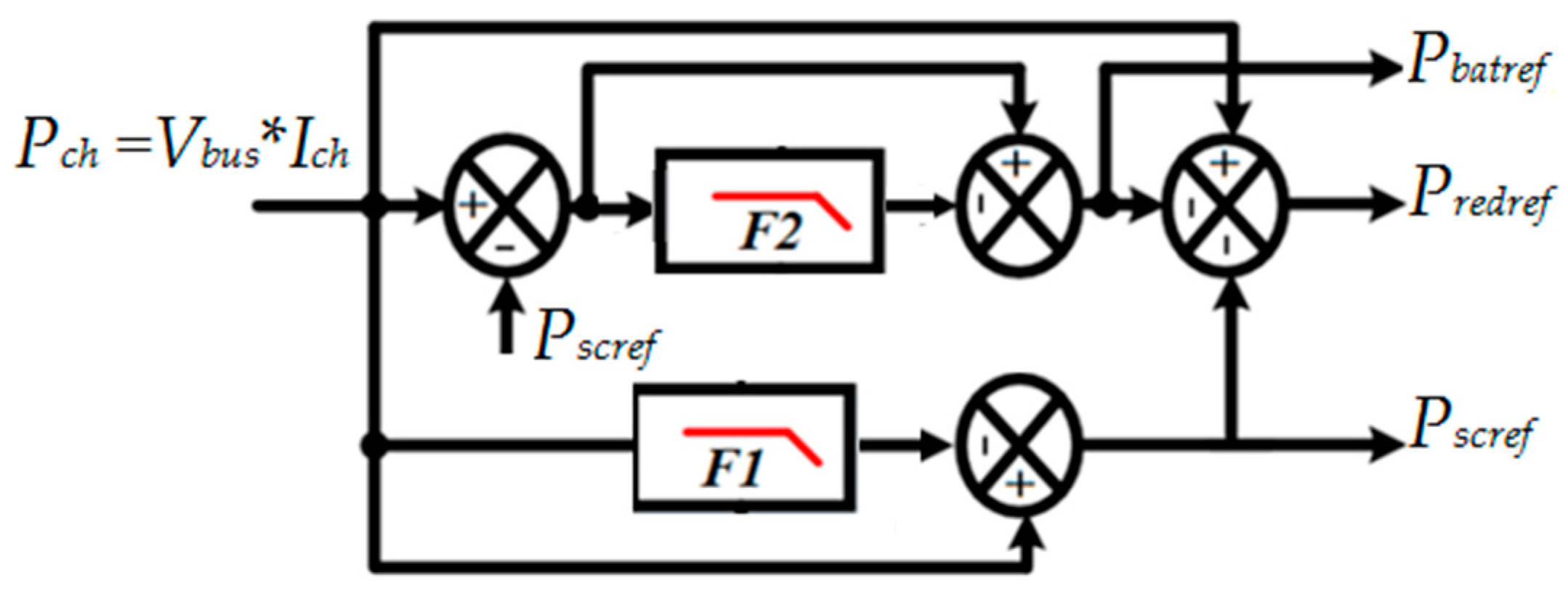
The coordinated power control uses the Dynamic Components Separation Concept (DCSC) of the load’s demand and its assignation to the sources. This method consists of sharing the power demand (Pch = Vbus*Ich) with a fast-dynamic power component, an average-dynamic power component, and low-dynamic ones, as shown in Figure 7. Dynamic components’ separation from the power demand is performed using two filters (F1 and F2) to obtain the average-dynamic power component and fast-dynamic components. Estimated profiles are assigned to the power sources according to their dynamic action capability. Therefore, the fast-dynamic power component is assigned to the supercapacitors Pscref, the average-dynamic power component is assigned to the batteries Pbatref, and the diesel generator supplies the low-dynamic power component Predref adapted to its dynamic action capability. The frequencies of the filters are f1 and f2, with f1 > f2. The frequency of the filters is related to the power density and energy density of the SCs/batteries. The maximum values of the frequencies are computed as shown in Equation (5). For a multi-source application-based variable-speed diesel generator (VSDG) and two energy storage systems (TESSs) controlled by the DCSC, the maximum values of the frequencies are not necessary because the sources (VSDG, supercapacitors, and batteries) operate in complementary situations. For this, f2 is fixed at 0.333 mHz with f1 ≈ 5*f2 with the aim of reducing the size of the supercapacitors and batteries. A global view of the coordinated power control is presented in Figure 8, which includes the control of the diesel generator speed, DC-bus voltage, and batteries/supercapacitors’ power as presented in the following subsections.
f 1 ρ p S C ρ e S C = 5.9     1000   W k g 6     3600   W · s k g = 270   m H z f 2 ρ p B a t ρ e B a t = 309.68   W k g 102.24     3600   W · s k g = 0.84   m H z

3.2. Diesel Generator Speed Control

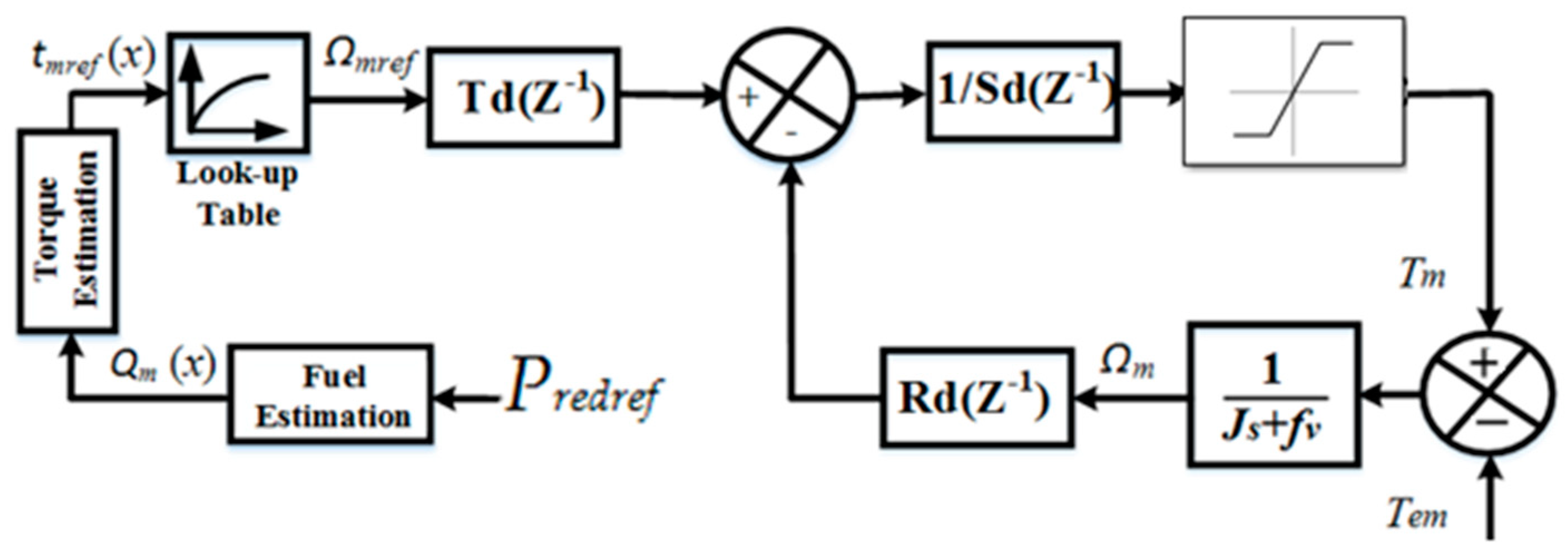
The speed control of the diesel generator (DG) consists of controlling the engine speed to maintain an efficient operating point. To do this, mechanical torque Tm is calculated as shown in Figure 9 based on Equation (6), where fv presents the viscous coefficient and Tem is the electromagnetic torque.
J d d t m + f v m = T m T e m T e m = 3 2 p φ m I s q + L d L q I s d I s q V s d = R s I s d + L d d d t I s d p m L q I s q V s q = R s I s q + L q d d t I s q + p m L d I s d + φ m
Equation (6) can be also expressed as presented in Equation (7), where the voltages in the stator are calculated from active power conservation through the controlled rectifier. Then, Isd and Isq currents can be computed using the S-function of MATLAB/Simulink.
V s d V b u s     I r e d     I s d I s d 2 + I s q 2 d d t I s d I s q = R s L d p     Ω m     L d L q p     Ω m     L q L d R s L q I s d I s q + V s d L d V s q p     Ω m     ϕ m L q V s q V b u s     I r e d     I s q I s d 2 + I s q 2
The speed reference of the diesel engine Ωmref is calculated using Equation (8), where tmref is the torque reference.
Q m x = λ 5 x 5 + λ 4 x 4 + λ 3 x 3 + λ 2 x 2 + λ 1 x + λ 0 t m r e f 1 1 + τ D 1 s 2 τ D 2 s 2 + τ D 2 s Q m ( x ) Ω m r e f = χ 4 t m r e f 4 + χ 3 t m r e f 3 + χ 2 t m r e f 2 + χ 1 t m r e f + χ 0 χ 0 = 148.87 ;   χ 1 = 6.58 ; χ 2 = 0.11 ;   χ 3 = 6.33 × 1 0 4 ; χ 4 = 1.29 × 1 0 6 λ 0 = 0.257 ;   λ 1 = 0.217 ;   λ 2 = 3.891 ;   λ 3 = 7.236 ;   λ 4 = 6.401 ; λ 5 = 2.108
In Equation (8), τD1 = 0.05 s presents a time constant-based diesel engine speed response limit; τD2 = 0.02 s is a time constant-based torque change period; x is the fuel flow index per unit (p.u.); Qm(x) presents the engine torque gain. In this paper, x is calculated using Equation (9), where Pnom = 400 kW is the nominal power of the Variable Speed Diesel Generator (VSDG). The VSDG parameters are shown in Table 4.
x P r e d r e f P n o m
The controllers of the DG speed are presented in Equation (10), where Td(z−1) and Rd(z−1) are considered the same regarding the goal of reducing the complexity of the control.
S d ( z 1 ) = 1 z 1 R d z 1 = T d z 1 = r 0 d + r 1 d z 1
The coefficients of Rd(z−1) are computed through a comparison of the desired polynomial and the denominator of the transfer function in a closed loop as shown in Equation (11), where A(z−1) is the denominator of the DG speed transfer function and B(z−1) is the numerator.
A z 1 S d z 1 + B z 1 R d z 1 = 1 z 1 exp ω n T e
The resulting coefficients are expressed in Equation (12), where Te represents the sampling period, ωa is the speed control bandwidth, J represents the total inertia of the VSDG, and fv represents the friction coefficient.
r 0 d = 2     J T e 1 exp ( ω a T e ) f v 2     J T e 1 1 1 + ω a T e f v r 1 d = J T e exp ( 2 ω a T e ) + T e     f v J 1 J T e 1 1 + 2 ω a T e + T e     f v J 1 ω a 0.15 f d

3.3. DC-Bus Voltage Control Method

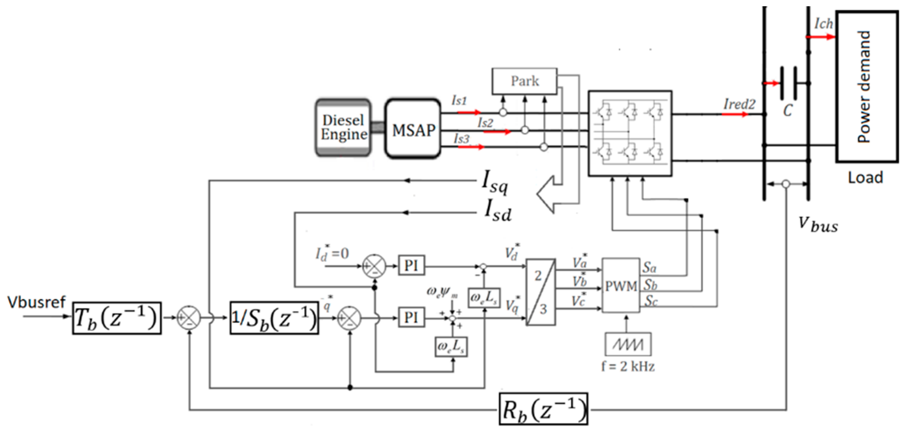
The DC-bus voltage control method based on mixed Polynomial-PI controllers is presented in Figure 10, where the inner loop is based on Isdq currents control and the outer loop is dedicated to the DC-bus voltage control. The reference current Isqref is calculated using the voltage control loop and Isdref is fixed to zero to obtain the best power factor. The controllers used in the DC-bus voltage control loop are given in Equation (13) [2,5,7].
S b ( z 1 ) = 1 z 1 R b z 1 = T b z 1 = r 0 b + r 1 b z 1
The coefficients of the controllers are presented in Equation (14), where CT is the total capacitor in the DC-bus, Te is the sampling period, ωv is the voltage control bandwidth, and fd is the AC/DC converter control frequency fixed at 2 kHz. Voltage references in the dq axis are estimated using PI controllers as presented in Equation (15), where ωn is the dq currents control bandwidth and ξ is the damping ratio fixed at 2 / 2 .
r 0 b = 2 1 exp ( ω v T e ) C T T e 2     C T T e 1 1 1 + ω v     T e r 1 b = exp ( 2 ω v T e ) 1 C T T e C T T e 1 1 + 2 ω v T e 1 ω v 0.32 f d C T = C + C s c + C b a t
V d = K p c 1 + K i c K p c     s I d I s d ω e L s I s q V q = K p c 1 + K i c K p c     s I q     I s q + ω e     L s     I s d + ω e     φ m K p c = 2 ξ L s   ω n R s K i c = L s   ω n 2  

3.4. Batteries’ and Supercapacitors’ Powers Control

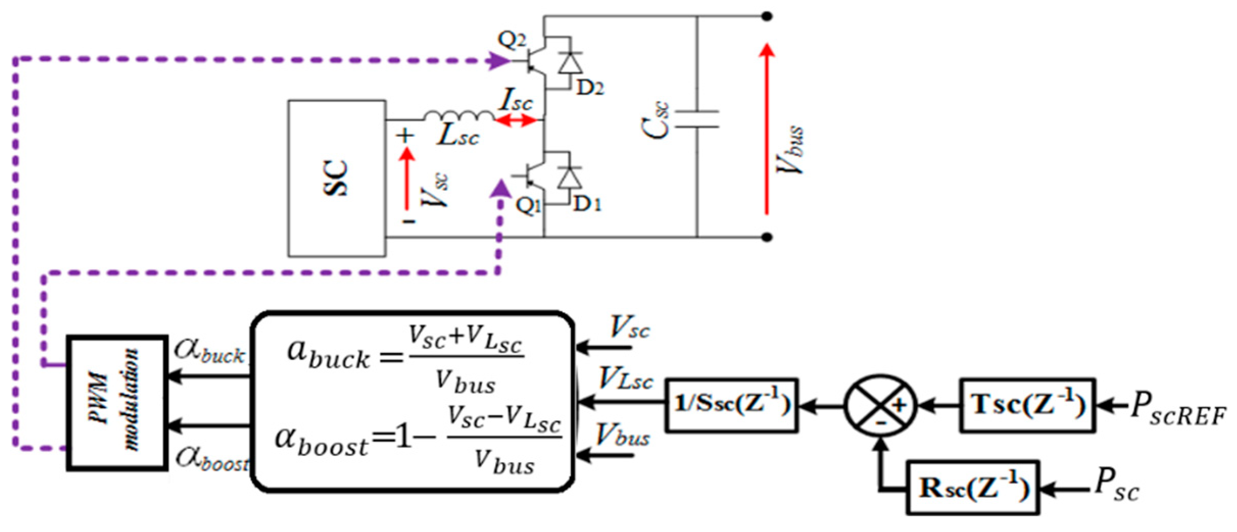
The packs of SCs and batteries are coupled in the DC-bus using two bidirectional DC/DC converters as shown in Figure 11 and Figure 12. The power profiles of the sources are calculated as shown in Figure 7. SCs’ and batteries’ voltages change frequently due to the fast-dynamic and average-dynamic power components of the load’s power demand, respectively. To avoid ruining the SCs or batteries, it is essential to add the voltage-supervising algorithms in the TESS power control loops, which corresponds to the limiting of energy storage (SCs, batteries) operation ranges. This action consists of keeping the voltages of the SCs and batteries in preconized operation ranges, i.e., between maximum and minimum values, to avoid the decline in SCs and batteries. The proposed method consists of using an offset in the dynamic power profiles (Pscref and Pbatref) extracted from Figure 7. Equation (16) presents the concept, where Pscref0 and Pbatref0 are the offsets of power from the supercapacitor and battery voltage-limiting algorithms.
P s c R E F = P s c r e f ,   i f   V s c m i n   V s c V s c m a x P s c r e f + P s c r e f 0 ,   i f   n o t P b a t R E F = P b a t r e f ,   i f   V b a t m i n   V b a t V b a t m a x P b a t r e f + P b a t r e f 0 ,   i f   n o t
Therefore, the batteries and the supercapacitors operate in preconized ranges. However, some safeguards are necessary when choosing Pscref0 and Pbatref0 values. If the values are large, the supercapacitors’ and batteries’ voltages rapidly reach the voltage limits. When the voltages of the supercapacitors and batteries reach the typical values, the offsets (Pscref0 and Pbatref0) can be immediately canceled. Quick charge–discharge of the SCs’ or batteries’ operations is not recommended because Pscref and Pbatref present a random evolution. Pscref0 and Pbatref0 are estimated to be approximately 1% of the maximum load’s power demand (300 kW). The SCs’ and batteries’ power controllers are presented in Equation (17).
S s c , b a t ( z 1 ) = 1 z 1 R s c , b a t ( z 1 ) = T s c , b a t ( z 1 ) = r 0 s c , b a t + r 1 s c , b a t z 1
The parameters used in the supercapacitors’ and batteries’ power control are calculated using Equation (18), where Lsc and Lbat are the inductances in buck-boost converters, Te is the sampling period, ωsc and ωbat represent the power control bandwidths, and fd represents the control frequency of the converters [2,5,7].
r 0 s c , b a t = 2 1 exp ( ω s c , b a t T e ) L s c , b a t T e 2     L s c , b a t T e 1 1 1 + ω s c , b a t     T e r 1 s c , b a t = exp ( 2 ω s c , b a t T e ) 1 L s c , b a t T e L s c , b a t T e 1 1 + 2     ω s c , b a t     T e 1 ω s c = 2 π f d ω b a t 0.1 ω s c
To control the power of the supercapacitors and batteries, the control laws given in Equation (19) are used to generate the control signals of (Q1, Q2, Q3, and Q4) for the two DC/DC converters [29].
a b u c k = V s c , b a t   +   V L s c , b a t V b u s α b o o s t = 1 V s c , b a t     V L s c , b a t V b u s
The supercapacitors’ and batteries’ power control loops are shown in Figure 11 and Figure 12, respectively, where the power references of the SCs and batteries (PscREF, PbatREF) are obtained from Equation (16). If the power control loops of the supercapacitors and batteries are employed, the low-dynamic power component of the load’s power demand will be supplied by the variable-speed DG.

4. Electric Ship Behavior Simulations

4.1. Conditions of the Simulations

A Hybrid Electric Ship is presented in Figure 2. This configuration includes a VSDG with a nominal power of 400 kW/50 Hz, a supercapacitors pack with a maximum voltage of 324 V, a batteries module with a maximum voltage of 270 V, two DC/DC converters, and the load. This last aspect is based on two thrusters with their interface power electronics and embedded appliances. The control of thrusters is not given here because the HES power demand is based on an existing diesel ship database. The parameters of the SCs and batteries change according to the temperature and load power transients used. Coordinated power control is implemented in MATLAB/Simulink software using the parameters presented in Table 5.

4.2. Simulation Results

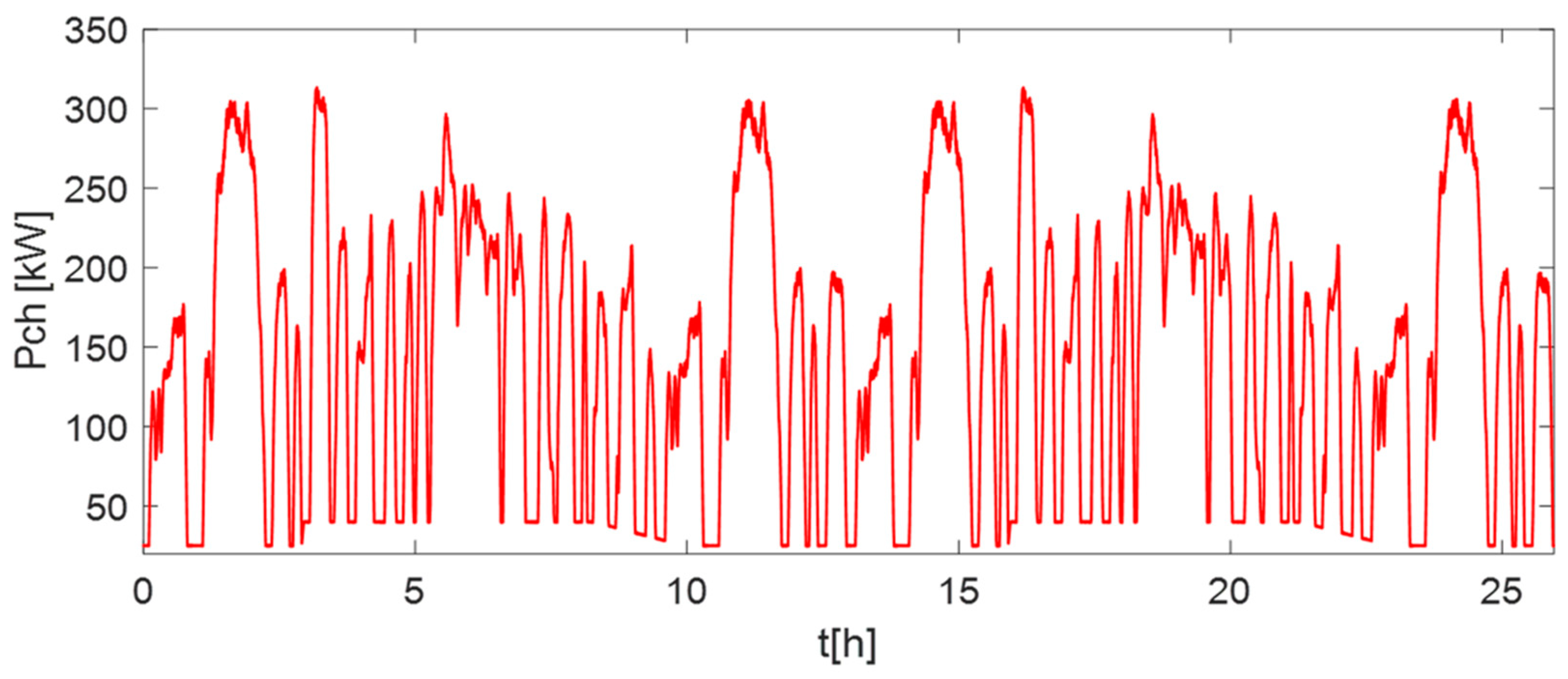
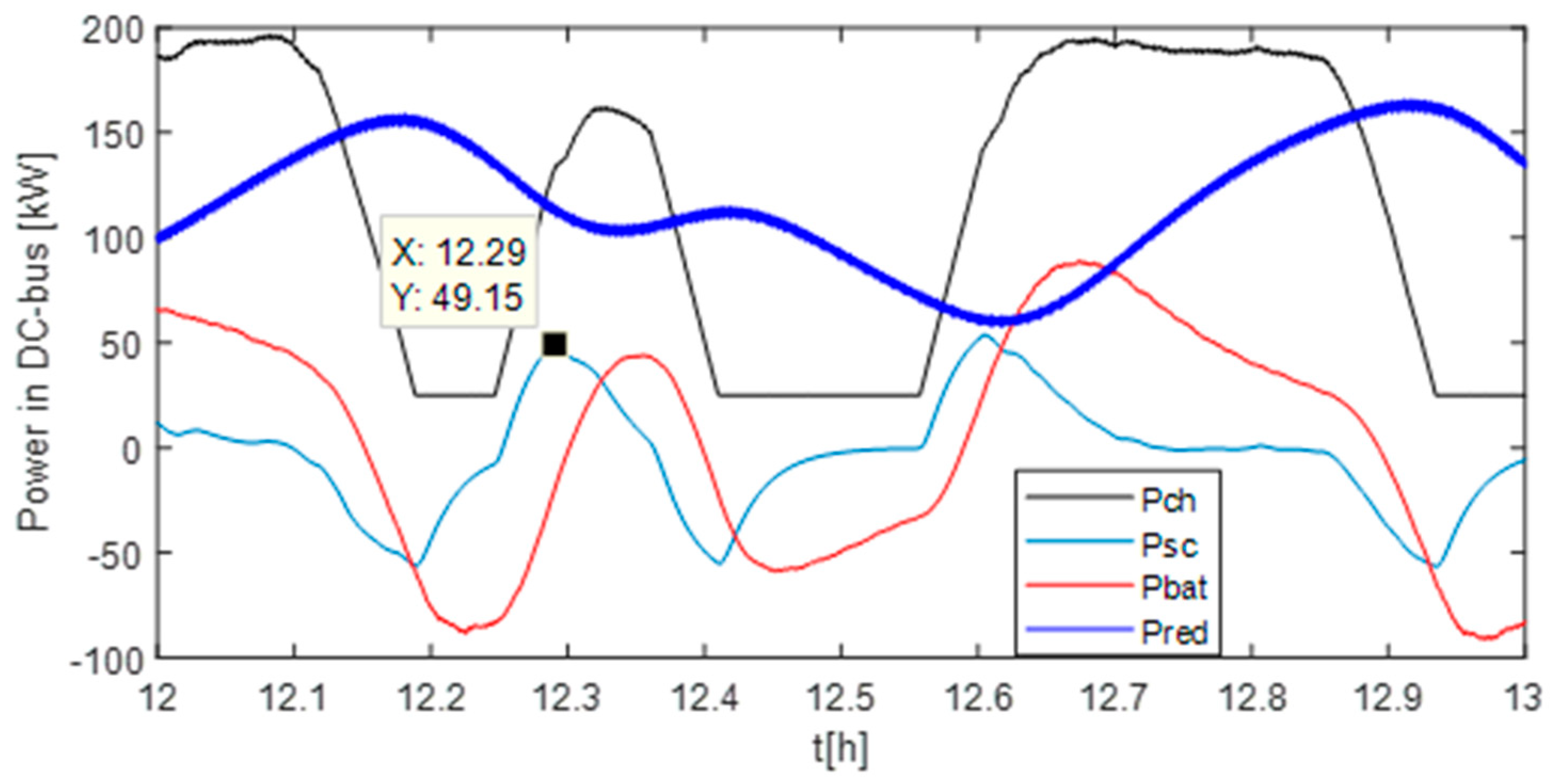
The typical profile of the load’s power demand based on one trip of the HES is presented in Figure 13. This power demand Pch is distributed to the fast-dynamic component Psc, average-dynamic component Pbat, and low-dynamic components Pred. To show the performances of the sources in the transient states, the contributions of the SCs/batteries and the VSDG are presented in Figure 14. These curves show that the peaks in power due to swift variations in the load are mitigated by the supercapacitors, the average-dynamic component is mitigated by the batteries, and the low-dynamic component is supplied by VSDG. In other words, the contributions of all sources decrease during low-load conditions, and the fast-dynamic component is supplied by the SCs, the average-dynamic component is provided by the batteries, and VSDG ensures the low-dynamic component.
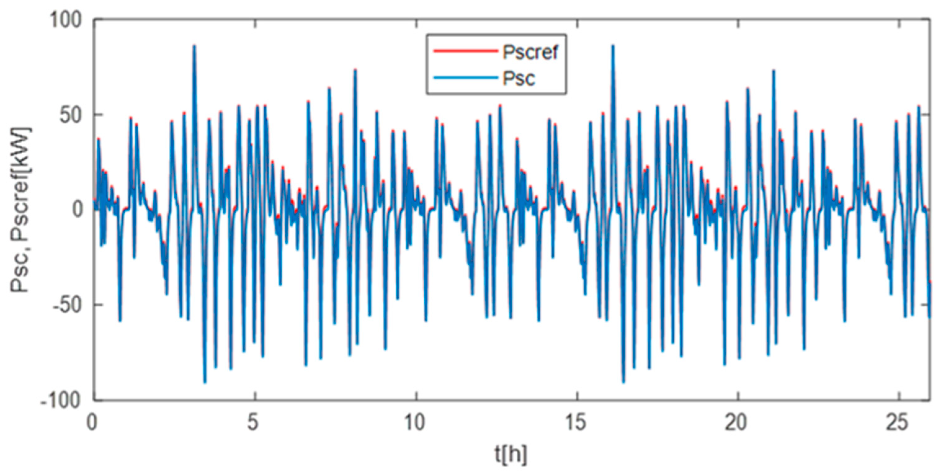
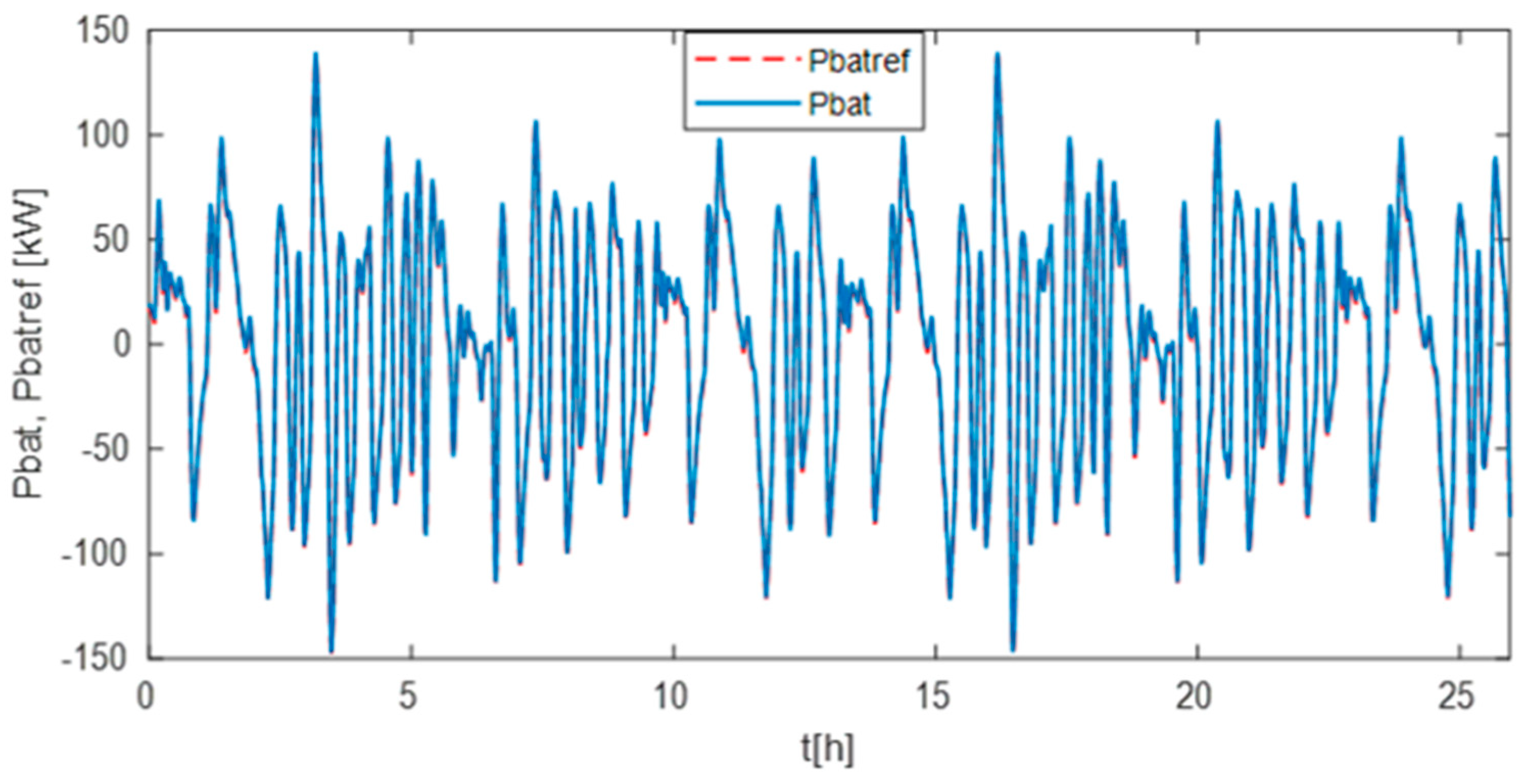
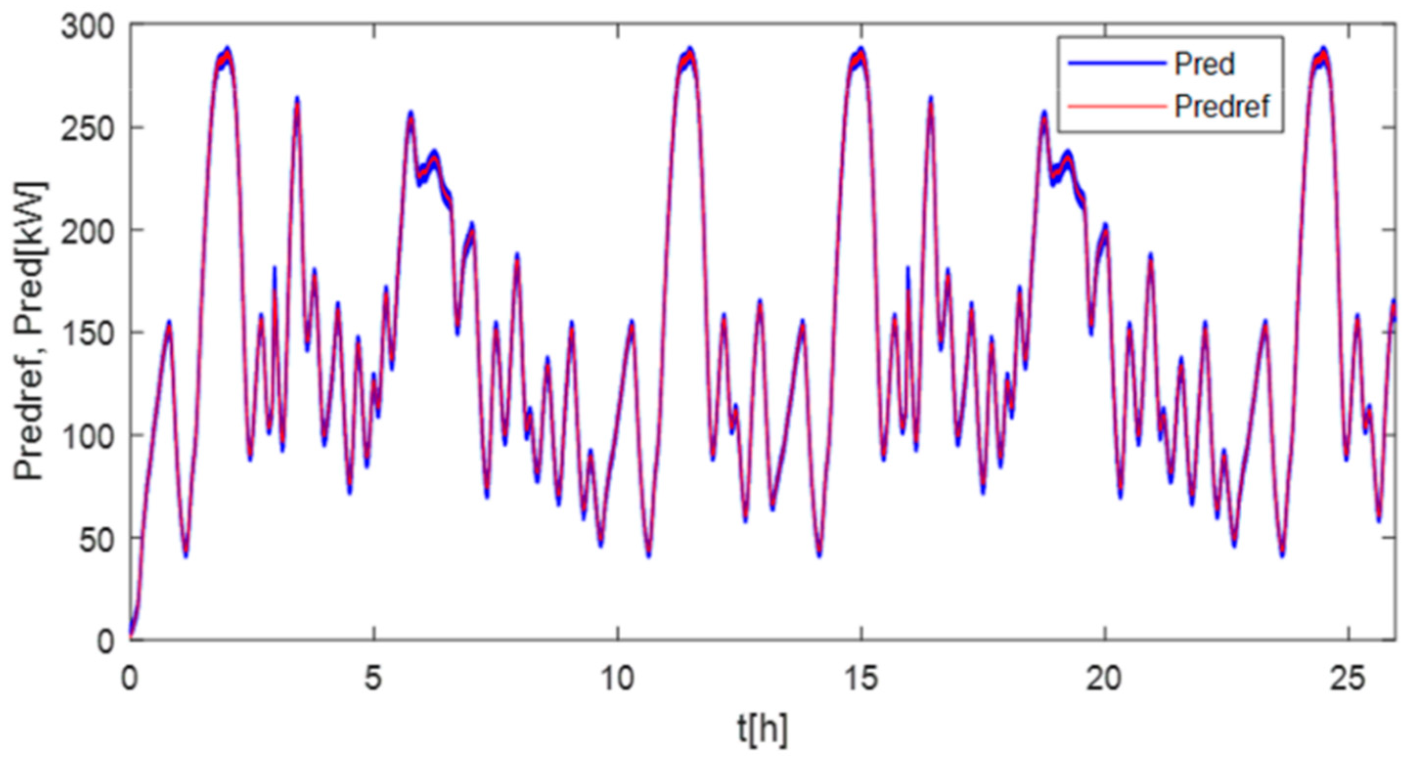
The power of SCs corresponding to the fast-dynamic component is presented in Figure 15. This figure shows that the fast-dynamic power from the load’s power demand is mitigated by the supercapacitors. The average-dynamic power from the load’s power demand is compensated for by the batteries, as presented in Figure 16. Figure 15 and Figure 16 show that the power of the SCs and batteries are close to their references, and fast-dynamic power fluctuations from the load’s power demand are mitigated by the supercapacitors and the average-dynamic power is ensured by the batteries. The proposed method allows us to reduce the impact of the fluctuations in the load’s power demand for the VSDG as illustrated by the low-dynamic power component presented in Figure 17, where the power variations are adapted to the dynamic characteristic of a variable-speed diesel engine. The DC-bus voltage reference is respectively fixed at 500 V and 800 V to illustrate the performances of the control, as plotted in Figure 18. Based on this result, the proposed DC-bus voltage control performs even under light-load conditions of the HES. In other words, the dynamic components of the load’s power demand are mitigated by the supercapacitors and batteries, which avoids the DC-bus voltage disturbance. The control result of the diesel generator speed is presented in Figure 19, where the controlled speed is close to the reference, which depends on the load’s power demand except during the no-load conditions where the VSDG must operate without the load’s demand to maintain the DC-bus voltage level.
These simulation results show that the coordinated power control using dynamic component separation of the power demand considering the dynamic performances of the connected sources [30,31] is interesting. This control technique avoids the supercapacitors/batteries being outsized as in the classic methods [29,30,31,32,33] for the same power demand profile and allows us to reduce the effect of the load’s power fluctuations on VSDG with a possible reduction in the CO2 [34]. However, the dynamic components assignation to the supercapacitors and batteries increases the electric stress on the SCs and batteries. This stress causes the rapid aging of the TESS [35,36].
The computed torque Tem based on Isq and Isd current control is illustrated in Figure 20. This figure shows a good correlation between the controlled torque Tem and its reference Tem-ref based on Isqref. In other words, the variations in the diesel generator’s torque are assigned to the Isq current, and the Isd current is maintained at zero through the control to obtain a unitary power factor.
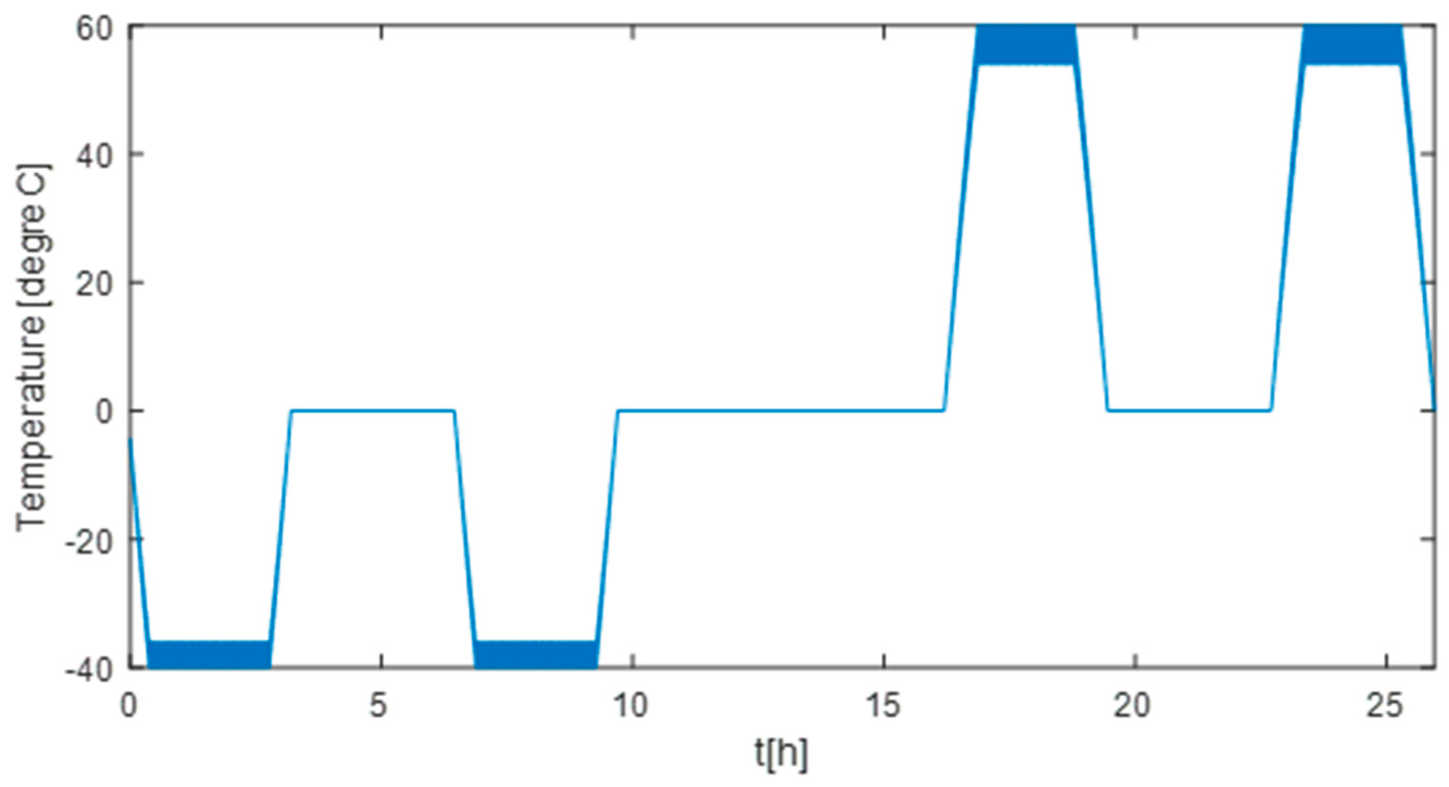
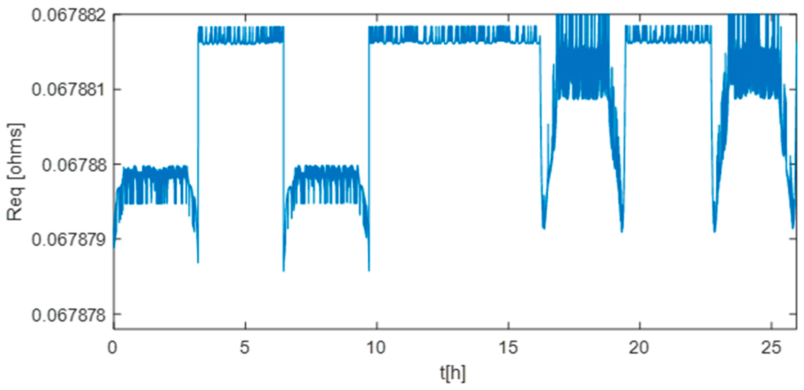
The impact of the temperature presented in Figure 21 on the supercapacitors’ parameters is illustrated in Figure 22 and Figure 23. These curves show that the SCs’ performance is better at −40 °C (minimum equivalent resistance Req of 67.880 mΩ and equivalent capacitance Ceq of 158 F) compared to that at 60 °C with an equivalent resistance Req of 67.882 mΩ and equivalent capacitance Ceq of 142 F. Based on Figure 22 and Figure 23, the negative temperature is the best operation conditions for the supercapacitors, where the equivalent resistance and equivalent capacitance are best compared to those obtained in positive-temperature conditions [10].
The variation in Ceq as a function of time, which is illustrated in Figure 23, is due, on the one hand, to the waveform of the power assigned to the SCs, and on the other hand, to the operating temperature change in the SCs. In real applications, the capacity is generally estimated at a time interval much greater than the sampling time; that is to say, it is not directly measurable, which makes it possible to attenuate the fluctuations of Ceq in practice.
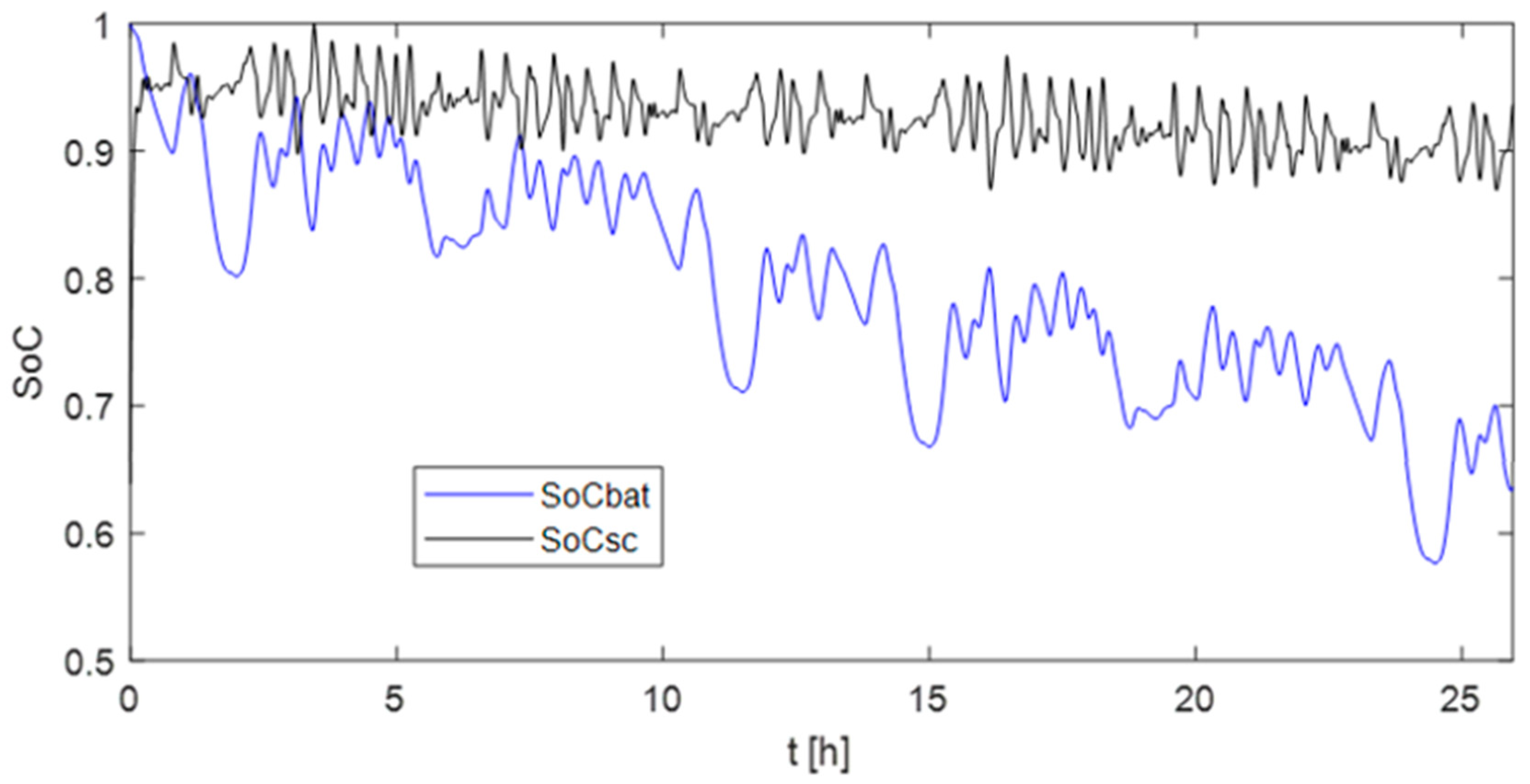
The SoCs of the supercapacitors module (SoCsc) and that of the batteries (SoCbat) are presented in Figure 24, where that of the batteries decreases more quickly due to the greater power demand. The fluctuations in the curves in Figure 24 are due to the phenomena of charge/discharge macrocycles of the supercapacitors and batteries.

5. Conclusions

This paper presents the coordinated power control of a Hybrid Electric Ship (HES) in transient situations, using the load power demand distribution based on the dynamic power components’ separation method. The control strategies of the DC-bus voltage and electric power are proposed and evaluated through HES behavior simulations. The performances of the proposed method are evaluated using simulations based on dynamic power components’ distribution between SCs and batteries. The simulations show that the proposed method is interesting regarding transient power control, where the power sources are not the same in terms of dynamic performance capabilities. Coordinated power control of the sources using the dynamic power components’ separation method enables us to share the load’s power requirements across the fast-dynamic power component, average-dynamic power component, and low-dynamic power component, where the fast-dynamic power component is assigned to the supercapacitors, the average-dynamic power component is assigned to the batteries, and the low-dynamic power component is provided by the diesel generator. The speed of the VSDG is controlled to follow the reference to ensure the good efficiency of the diesel engine. In summary, the power control using the dynamic power components’ assignation considers the dynamic response capabilities of the sources. This concept allows us to reduce the impacts of the load’s power variations for VSDG without knowing the profile of the load’s power demand (database) because the HES energy demand changes frequently in real applications. Therefore, the TESS can be sized using only the fast-dynamic power component for the supercapacitors and the average-dynamic power component for the batteries, which allows us to reduce the capacities of the batteries and supercapacitors to the optimal size adapted to the load’s power fluctuations. The strength of this paper compared to previous works is its focus on coordinated power control based on the HES fast-acting improvement during sudden power demand changes using supercapacitors–batteries. The novelty concerns the electric energy management considering SCs’ parameter dependency on temperature and their fast-acting capability during transient operations of the HES. An additional contribution is the electrothermal modeling of the SCs with the extension of the current ripples’ frequency range.

Author Contributions

Conceptualization, M.B.C.; methodology, M.B.C.; software, M.B.C.; formal analysis, M.B.C.; data curation, M.B.C.; writing—original draft preparation, M.B.C.; writing—review and editing, M.B.C. and B.D.; visualization, M.B.C. and B.D.; supervision, M.B.C. and B.D.; project administration, M.B.C. and B.D.; funding acquisition, M.B.C. and B.D. All authors have read and agreed to the published version of the manuscript.

Funding

This research received no external funding.

Data Availability Statement

The data presented in this study are available upon request from the corresponding authors.

Acknowledgments

The authors would like to thank the Council of the Region Normandy/France, and University of Le Havre Normandie for their financial support.

Conflicts of Interest

The authors declare no conflict of interest.

Abbreviations

SCSupercapacitor
PMSGPermanent Magnet Synchronous Generator
VSDGVariable Speed Diesel Generator
HESHybrid Electric Ship
TESSTwo Energy Storage System
Vbus & VbusrefDC-bus voltage and its reference in [V]
VbatBatteries voltage in [V]
VscSupercapacitors voltage in [V]
PscPower of the SC
PbatPower of the batteries
PchPower of the load in [kW]
PredPower of the VSDG
Sa, Sb, ScControl signals of the rectifier
TeSampling period in [s]
Vsd & VsqVoltage of the PMSG in dq axis in [V]

References

  1. Trovão, J.P.; Machado, F.; Pereirinha, P.G. Hybrid electric excursion ships power supply system based on a multiple energy storage system. IET Electr. Syst. Transp. 2015, 6, 190–201. [Google Scholar] [CrossRef]
  2. Bellache, K.; Camara, M.; Dakyo, B. Hybrid Electric Boat based on variable speed Diesel Generator and lithium-battery—Using frequency approach for energy management. In Proceedings of the 2015 Intl Aegean Conference on Electrical Machines & Power Electronics (ACEMP), 2015 Intl Conference on Optimization of Electrical & Electronic Equipment (OPTIM) & 2015 Intl Symposium on Advanced Electromechanical Motion Systems (ELECTROMOTION), Side, Turkey, 2–4 September 2015; pp. 744–749. [Google Scholar] [CrossRef]
  3. Lidozzi, A.; Solero, L.; Crescimbini, F. Adaptive Direct-Tuning Control for Variable-Speed Diesel-Electric Generating Units. IEEE Trans. Ind. Electron. 2012, 59, 2126–2134. [Google Scholar] [CrossRef]
  4. Zhou, Z.; Camara, M.B.; Dakyo, B. Coordinated Power Control of Variable-Speed Diesel Generators and Lithium-Battery on a Hybrid Electric Boat. IEEE Trans. Veh. Technol. 2017, 66, 5775–5784. [Google Scholar] [CrossRef]
  5. Oukkacha, I.; Camara, M.B.; Dakyo, B. Energy Management in Electric Vehicle based on Frequency sharing approach, using Fuel cells, Lithium batteries and Supercapacitors. In Proceedings of the 2018 7th International Conference on Renewable Energy Research and Applications (ICRERA), Paris, France, 14–17 October 2018; pp. 986–992. [Google Scholar] [CrossRef]
  6. Trovao, J.P.F.; Santos, V.D.N.; Antunes, C.H.; Pereirinha, P.G.; Jorge, H.M. A Real-Time Energy Management Architecture for Multisource Electric Vehicles. IEEE Trans. Ind. Electron. 2015, 62, 3223–3233. [Google Scholar] [CrossRef]
  7. Tani, A.; Camara, M.B.; Dakyo, B.; Azzouz, Y. DC/DC and DC/AC Converters Control for Hybrid Electric Vehicles Energy Management-Ultracapacitors and Fuel Cell. IEEE Trans. Ind. Informatics 2013, 9, 686–696. [Google Scholar] [CrossRef]
  8. Huang, Y.; Wang, H.; Khajepour, A.; Li, B.; Ji, J.; Zhao, K.; Hu, C. A review of power management strategies and component sizing methods for hybrid vehicles. Renew. Sustain. Energy Rev. 2018, 96, 132–144. [Google Scholar] [CrossRef]
  9. Hossain, M.; Rahim, N.; Selvaraj, J.A. Recent progress and development on power DC-DC converter topology, control, design and applications: A review. Renew. Sustain. Energy Rev. 2018, 81, 205–230. [Google Scholar] [CrossRef]
  10. Sorlei, I.-S.; Bizon, N.; Thounthong, P.; Varlam, M.; Carcadea, E.; Culcer, M.; Iliescu, M.; Raceanu, M. Fuel Cell Electric Vehicles—A Brief Review of Current Topologies and Energy Management Strategies. Energies 2021, 14, 252. [Google Scholar] [CrossRef]
  11. Odeim, F.; Roes, J.; Heinzel, A. Power Management Optimization of an Experimental Fuel Cell/Battery/Supercapacitor Hybrid System. Energies 2015, 8, 6302–6327. [Google Scholar] [CrossRef]
  12. Sampietro, J.L.; Puig, V.; Costa-Castelló, R. Optimal Sizing of Storage Elements for a Vehicle Based on Fuel Cells, Supercapacitors, and Batteries. Energies 2019, 12, 925. [Google Scholar] [CrossRef]
  13. Gherairi, S. Hybrid Electric Vehicle: Design and Control of a Hybrid System (Fuel Cell/Battery/Ultra-Capacitor) Supplied by Hydrogen. Energies 2019, 12, 1272. [Google Scholar] [CrossRef]
  14. Nassef, A.M.; Fathy, A.; Rezk, H. An Effective Energy Management Strategy Based on Mine-Blast Optimization Technique Applied to Hybrid PEMFC/Supercapacitor/Batteries System. Energies 2019, 12, 3796. [Google Scholar] [CrossRef]
  15. Cao, Y.; Kroeze, R.C.; Krein, P.T. Multi-timescale Parametric Electrical Battery Model for Use in Dynamic Electric Vehicle Simulations. IEEE Trans. Transp. Electrif. 2016, 2, 432–442. [Google Scholar] [CrossRef]
  16. Bellache, K.; Camara, M.B.; Dakyo, B.; Ramasamy, S. Aging Characterization of Lithium Iron Phosphate Batteries Considering Temperature and Direct Current Undulations as Degrading Factors. IEEE Trans. Ind. Electron. 2020, 68, 9696–9706. [Google Scholar] [CrossRef]
  17. Lee, Y.-D.; Park, S.-Y.; Han, S.-B. Online Embedded Impedance Measurement Using High-Power Battery Charger. IEEE Trans. Ind. Appl. 2015, 51, 498–508. [Google Scholar] [CrossRef]
  18. Bruen, T.; Marco, J. Modelling and experimental evaluation of parallel connected lithium ion cells for an electric vehicle battery system. J. Power Sources 2016, 310, 91–101. [Google Scholar] [CrossRef]
  19. Zhao, X.; Wu, X.; Li, Y.; Tian, H. Energy management strategy of multiple supercapacitors in an autonomous DC microgrid using adaptive virtual impedance. In Proceedings of the 2016 IEEE 7th International Symposium on Power Electronics for Distributed Generation Systems (PEDG), Vancouver, BC, Canada, 27–30 June 2016; pp. 1174–1185. [Google Scholar] [CrossRef]
  20. Gandolfo, D.; Brandão, A.; Patiño, D.; Molina, M. Dynamic model of lithium polymer battery—Load resistor method for electric parameters identification. J. Energy Inst. 2015, 88, 470–479. [Google Scholar] [CrossRef]
  21. Bellache, K.; Camara, M.B.; Dakyo, B. Transient Power Control for Diesel-Generator Assistance in Electric Boat Applications Using Supercapacitors and Batteries. IEEE J. Emerg. Sel. Top. Power Electron. 2018, 6, 416–428. [Google Scholar] [CrossRef]
  22. El Mejdoubi, A.; Chaoui, H.; Gualous, H.; Sabor, J. Online Parameter Identification for Supercapacitor State-of-Health Diagnosis for Vehicular Applications. IEEE Trans. Power Electron. 2017, 32, 9355–9363. [Google Scholar] [CrossRef]
  23. Ahmad, H.; Wan, W.Y.; Isa, D. Modeling the Ageing Effect of Cycling Using a Supercapacitor-Module Under High Temperature with Electrochemical Impedance Spectroscopy Test. IEEE Trans. Reliab. 2018, 68, 109–121. [Google Scholar] [CrossRef]
  24. Liu, W.; Song, Y.; Liao, H.; Li, H.; Zhang, X.; Jiao, Y.; Peng, J.; Huang, Z. Distributed Voltage Equalization Design for Supercapacitors Using State Observer. IEEE Trans. Ind. Appl. 2018, 55, 620–630. [Google Scholar] [CrossRef]
  25. Murray, D.B.; Hayes, J.G. Cycle Testing of Supercapacitors for Long-Life Robust Applications. IEEE Trans. Power Electron. 2015, 30, 2505–2516. [Google Scholar] [CrossRef]
  26. Bellache, K.; Camara, M.B.; Dakyo, B. Supercapacitors Characterization and Modeling Using Combined Electro-Thermal Stress Approach Batteries. IEEE Trans. Ind. Appl. 2018, 55, 1817–1827. [Google Scholar] [CrossRef]
  27. Sarr, C.T.; Camara, M.B.; Dakyo, B. Supercapacitors aging assessment in wind/tidal intermittent energies application with variable temperature. J. Energy Storage 2021, 46, 103790. [Google Scholar] [CrossRef]
  28. Corti, F.; Gulino, M.-S.; Laschi, M.; Lozito, G.M.; Pugi, L.; Reatti, A.; Vangi, D. Time-Domain Circuit Modelling for Hybrid Supercapacitors. Energies 2021, 14, 6837. [Google Scholar] [CrossRef]
  29. Tankari, M.A.; Camara, M.B.; Dakyo, B.; Lefebvre, G. Use of Ultracapacitors and Batteries for Efficient Energy Management in Wind–Diesel Hybrid System. IEEE Trans. Sustain. Energy 2013, 4, 414–424. [Google Scholar] [CrossRef]
  30. Broomhead, T.; Manzie, C.; Hield, P.; Shekhar, R.; Brear, M. Economic Model Predictive Control and Applications for Diesel Generators. IEEE Trans. Control. Syst. Technol. 2016, 25, 388–400. [Google Scholar] [CrossRef]
  31. Hussain, S.; Ali, M.U.; Park, G.-S.; Nengroo, S.H.; Khan, M.A.; Kim, H.-J. A Real-Time Bi-Adaptive Controller-Based Energy Management System for Battery–Supercapacitor Hybrid Electric Vehicles. Energies 2019, 12, 4662. [Google Scholar] [CrossRef]
  32. Camara, M.B.; Gualous, H.; Gustin, F.; Berthon, A.; Dakyo, B. DC/DC Converter Design for Supercapacitor and Battery Power Management in Hybrid Vehicle Applications—Polynomial Control Strategy. IEEE Trans. Ind. Electron. 2010, 57, 587–597. [Google Scholar] [CrossRef]
  33. Azuara-Grande, L.S.; Arnaltes, S.; Alonso-Martinez, J.; Rodriguez-Amenedo, J.L. Comparison of Two Energy Management System Strategies for Real-Time Operation of Isolated Hybrid Microgrids. Energies 2021, 14, 6770. [Google Scholar] [CrossRef]
  34. Lau, H.C.; Ramakrishna, S.; Zhang, K.; Hameed, M.Z.S. A Decarbonization Roadmap for Singapore and Its Energy Policy Implications. Energies 2021, 14, 6455. [Google Scholar] [CrossRef]
  35. Baqar, A.; Camara, M.B.; Dakyo, B. Supercapacitors Fast Ageing Control in Residential Microgrid Based Photovoltaic/Fuel Cell/Electric Vehicle Charging Station. Energies 2023, 16, 5084. [Google Scholar] [CrossRef]
  36. Mariscotti, A. Power Quality Phenomena, Standards, and Proposed Metrics for DC Grids. Energies 2021, 14, 6453. [Google Scholar] [CrossRef]
Figure 1. Freight transport Hybrid Electric Ship.
Energies 16 06666 g001
Figure 2. Hybrid Electric Ship Power circuit configuration.
Energies 16 06666 g002
Figure 3. LiFePO4 batteries behavior model, where Voc = Voc (SoC).
Energies 16 06666 g003
Figure 4. SC cell resistance depending on the temperature and frequency of current ripples.
Energies 16 06666 g004
Figure 5. Capacitance of the SC cell depending on the T and frequency of current ripples.
Energies 16 06666 g005
Figure 6. Model of the supercapacitor module.
Energies 16 06666 g006
Figure 7. Power profile estimation for the SCs–batteries Variable-Speed Diesel Generator.
Energies 16 06666 g007
Figure 8. Coordinated power control principle for Hybrid Electric Ship Application.
Energies 16 06666 g008
Figure 9. DG Speed control loop.
Energies 16 06666 g009
Figure 10. DC-bus voltage control using mixed Polynomial-PI controllers, where I d = I s d r e f and I q = I s q r e f . In terms of control, the difference compared to the work presented in Ref. [21] concerns the use of mixed Polynomial-PI controllers, which consider the system parameter change.
Energies 16 06666 g010
Figure 11. Supercapacitors’ power control loop.
Energies 16 06666 g011
Figure 12. Batteries’ power control loop.
Energies 16 06666 g012
Figure 13. Hybrid Electric Ship power demand.
Energies 16 06666 g013
Figure 14. Contributions of the sources in transient operations, where Pred is the power of the diesel generator, Psc is the power of the SCs, Pbat is the power of the batteries, and Pch is the load’s power demand.
Energies 16 06666 g014
Figure 15. Fast-dynamic power component from the supercapacitors.
Energies 16 06666 g015
Figure 16. Average-dynamic power component from the batteries.
Energies 16 06666 g016
Figure 17. Low-dynamic power component supplied by VSDG.
Energies 16 06666 g017
Figure 18. DC-bus voltage control result.
Energies 16 06666 g018
Figure 19. Speed control result of the VSDG.
Energies 16 06666 g019
Figure 20. Torque of the variable-speed diesel generator.
Energies 16 06666 g020
Figure 21. Supercapacitors’ operating temperature.
Energies 16 06666 g021
Figure 22. Equivalent resistance of the supercapacitors pack.
Energies 16 06666 g022
Figure 23. Equivalent capacitance of the supercapacitors pack.
Energies 16 06666 g023
Figure 24. SoC of the supercapacitors and batteries.
Energies 16 06666 g024
Table 1. Performances of the batteries compared to the supercapacitors.
Basic CharacteristicsSupercapacitorsLi-ion Batteries
Capacity cost in [€/kWh]279~18,600465~3534
Life time in [cycles]100,000~1,000,000500~2000
Efficiency in [%]75~9870~90
Self-discharge in [%/day]20~400.33
Table 2. Parameters used in battery module based on LiFePO4 ~100 Ah/3.2 V cell.
Parameters of the Batteries ModuleValues
VBatmin~VBatmaxBattery’s cell voltage range in [V]2.8~3.8
R1* C1First order time constant in [Ω* F]0.033*92
R2* C2Second order time constant in [Ω* F]0.375*499
ρPBatSpecific power in [W/kg]310
ρEBatSpecific energy in [Wh/kg]102
SoC(t0)Initial value of SoC [%]97
Ns_BatNumber of the battery’s cells in series71
NP_BatNumber of the sub-modules in parallel8
RbwiResistance of electric wiring for a battery’s cell in [m Ω]4.5
Table 3. Parameters of the SC module-based 3000 F/2.7 V cell.
Parameters of the SC ModuleValues
VSCmin~VSCmaxVoltage range of the SC cell in [V]0.7~2.7
ρPSCSpecific power in [W/kg]5900
ρESCSpecific energy in [Wh/kg]6
SoC(t0)Initial value of the SoC [%]80
Ns_SCSupercapacitors cells in series120
NP_SCSub-modules of the supercapacitors in parallel7
RwiWiring resistance of a SC cell in [m Ω]4.47
Table 4. Parameters of Variable Speed Diesel Generator (VSDG).
Parameters of the VSDGValues
PnomDG nominal power in [kW]400
nDG nominal speed in [rpm]1500
τD1Actuator time constant of DG in [s]0.05
τD2Fuel combustion delay in [s]0.02
pPair of poles9
RsResistance of the PMSG in [mΩ]14
Ls = Ld = LqInductance of the PMSG in [mH]8.1
φmPMSG rotor flux in [Wb]0.9
JTotal inertia of VSDG in [kg.m2]4.562
fvFriction coefficient0.0024
Table 5. HES System control parameters.
Parameters of the ControlValues
Capacitances in DC-busCbat = Csc = 2 mF; C = 30 mF
Inductance in DC/DC converters
Tb(Z−1) = Rb (Z−1) = r0b + r1b*Z−1
Lsc = Lbat = 0.18 mH
28.58–26.09*Z−1
Tbat (Z−1) = Rbat (Z−1) = r0bat + r1bat* Z−118–16*Z−1
Tsc (Z−1) = Rsc (Z−1) = r0sc + r1sc*Z−174.44–40.23*Z−1
Td (Z−1) = Rd (Z−1) = r0d + r1d*Z−11909–1832.3*Z−1
Kpc; Kic2.5; 20
Disclaimer/Publisher’s Note: The statements, opinions and data contained in all publications are solely those of the individual author(s) and contributor(s) and not of MDPI and/or the editor(s). MDPI and/or the editor(s) disclaim responsibility for any injury to people or property resulting from any ideas, methods, instructions or products referred to in the content.