
Topology Review of Three-Phase Two-Level Transformerless Photovoltaic Inverters for Common-Mode Voltage Reduction

 ,
,  ,
,  ,
,  ,
,  and
and 
Abstract
:1. Introduction
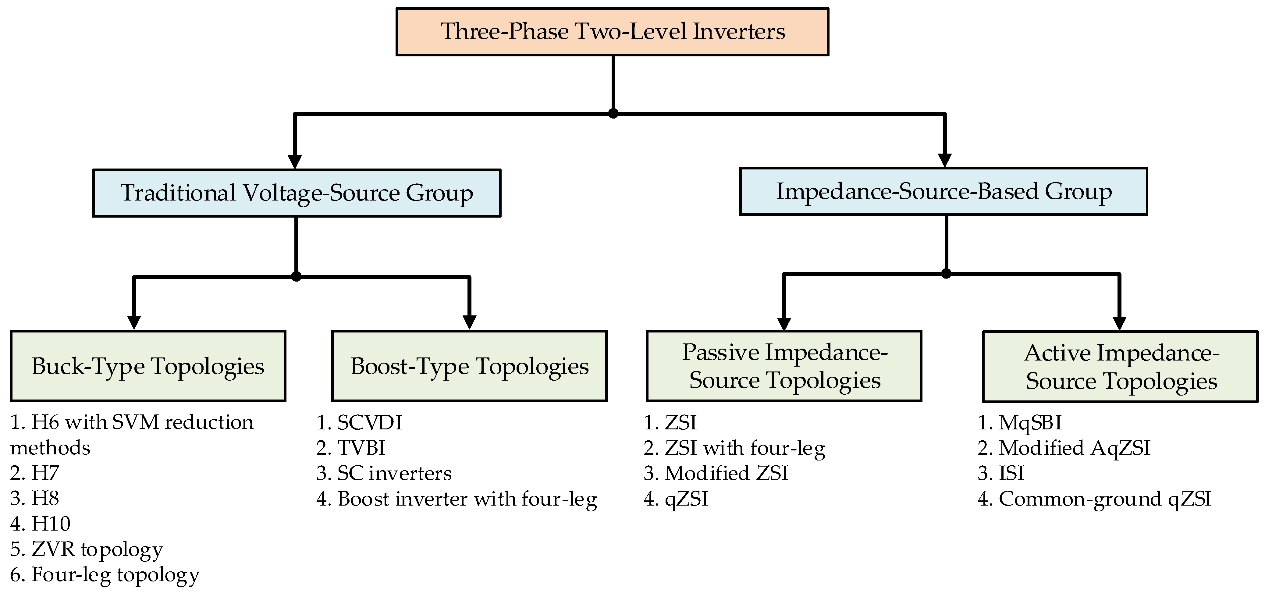
2. Classification of Three-Phase Two-Level Transformerless Topologies for CMV Reduction
3. Traditional Voltage Source Topologies
3.1. Buck-Type Topologies
3.2. Boost-Type Topologies
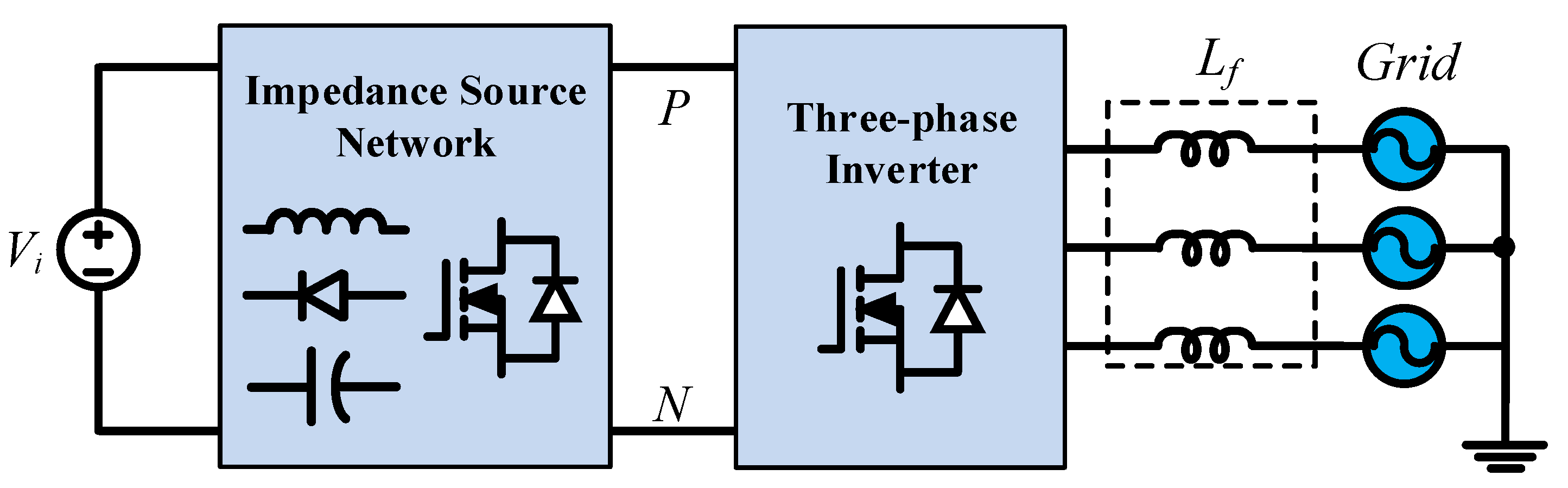
4. Impedance-Source-Networks-Based Topologies
4.1. Passive-Type Topologies
4.2. Active-Type Topologies
5. Conclusions
Author Contributions
Funding
Institutional Review Board Statement
Informed Consent Statement
Data Availability Statement
Conflicts of Interest
Abbreviations
| PV | Photovoltaic |
| DC | Direct current |
| AC | Alternating current |
| VSIs | Voltage source inverters |
| CSIs | Current source inverters |
| CMV | Common-mode voltage |
| SVM | Space vector modulation |
| PWM | Pulse width modulation |
| THD | Total harmonic distortion |
| ZSI | Z-source inverter |
| DSVM | Discontinuous space vector modulation |
| NSSVM | Near-state space vector modulation |
| AZSVM | Active zero-state space vector modulation |
| RSSVM | Remote-state space vector modulation |
References
- Almutairi, A.; Sayed, K.; Albagami, N.; Abo-Khalil, A.G.; Saleeb, H. Multi-Port PWM DC-DC Power Converter for Renewable Energy Applications. Energies 2021, 14, 3490. [Google Scholar] [CrossRef]
- Abramovitz, A.; Shmilovitz, D. Short Survey of Architectures of Photovoltaic Arrays for Solar Power Generation Systems. Energies 2021, 14, 4917. [Google Scholar] [CrossRef]
- Bughneda, A.; Salem, M.; Richelli, A.; Ishak, D.; Alatai, S. Review of Multilevel Inverters for PV Energy System Applications. Energies 2021, 14, 1585. [Google Scholar] [CrossRef]
- Subramaniam, U.; Bhaskar, S.M.; Almakhles, D.J.; Padmanaban, S.; Leonowicz, Z. Investigations on EMI Mitigation Techniques: Intent to Reduce Grid-Tied PV Inverter Common Mode Current and Voltage. Energies 2019, 12, 3395. [Google Scholar] [CrossRef] [Green Version]
- Nguyen, M.K.; Duong, T.D.; Lim, Y.C.; Kim, Y.J. Isolated boost DC-DC converter with three switches. IEEE Trans. Power Electron. 2018, 33, 1389–1398. [Google Scholar] [CrossRef]
- Duong, T.D.; Nguyen, M.K.; Tran, T.T.; Lim, Y.C.; Choi, J.H. Transformerless High Step-Up DC-DC Converters with Switched-Capacitor Network. Electronics 2019, 8, 1420. [Google Scholar] [CrossRef] [Green Version]
- Kouro, S.; Leon, J.I.; Vinnikov, D.; Franquelo, L.G. Grid-connected photovoltaic systems: An overview of recent research and emerging PV converter technology. IEEE Ind. Electron. Mag. 2015, 9, 47–61. [Google Scholar] [CrossRef]
- Nguyen, M.K.; Duong, T.D.; Lim, L.C. Switched-capacitor-based dual-switch high-boost DC-DC converter. IEEE Trans. Power Electron. 2018, 33, 4181–4189. [Google Scholar] [CrossRef]
- Duong, T.D.; Nguyen, M.K.; Tran, T.T.; Lim, Y.C.; Choi, J.H. Transformer-Less Switched-Capacitor Quasi-Switched Boost DC-DC Converter. Energies 2021, 14, 6591. [Google Scholar] [CrossRef]
- Mohamed Hariri, M.H.; Mat Desa, M.K.; Masri, S.; Mohd Zainuri, M.A.A. Grid-Connected PV Generation System-Components and Challenges: A Review. Energies 2020, 13, 4279. [Google Scholar] [CrossRef]
- Ali Khan, M.Y.; Liu, H.; Yang, Z.; Yuan, X. A Comprehensive Review on Grid Connected Photovoltaic Inverters, Their Modulation Techniques, and Control Strategies. Energies 2020, 13, 4185. [Google Scholar] [CrossRef]
- Jo, K.Y.; Duong, T.D.; Nguyen, Y.C.; Choi, J.H. Emerging Technologies in Power Systems. Electronics 2022, 11, 71. [Google Scholar] [CrossRef]
- Zhai, L.; Lin, L.; Zhang, X.; Song, C. The Effect of Distributed Parameters on Conducted EMI from DC-Fed Motor Drive Systems in Electric Vehicles. Energies 2017, 10, 1. [Google Scholar] [CrossRef] [Green Version]
- Monjo, L.; Sainz, L.; Mesas, J.J.; Pedra, J. Quasi-Z-Source Inverter-Based Photovoltaic Power System Modeling for Grid Stability Studies. Energies 2021, 14, 508. [Google Scholar] [CrossRef]
- Duong, T.D.; Nguyen, M.K.; Lim, Y.C.; Choi, J.H.; Wang, C.; Vilathgamuwa, M. Modeling and Control of a Discontinuous Quasi-Switched Boost Cascaded Multilevel Inverter for Grid-Tied Applications. In Proceedings of the 2020 IEEE Energy Conversion Congress and Exposition (ECCE), Detroit, MI, USA, 11–15 October 2020; pp. 3261–3265. [Google Scholar]
- Kerekes, T.; Teodorescu, R.; Liserre, M.; Klumpner, C.; Sumner, M. Evaluation of Three-Phase Transformerless Photovoltaic Inverter Topologies. IEEE Trans. Power Electron. 2009, 24, 2202–2211. [Google Scholar] [CrossRef]
- Tang, Y.; Yao, W.; Loh, P.C.; Blaabjerg, F. Highly Reliable Transformerless Photovoltaic Inverters with Leakage Current and Pulsating Power Elimination. IEEE Trans. Ind. Electron. 2016, 63, 1016–1026. [Google Scholar] [CrossRef]
- Yang, B.; Li, W.; Gu, Y.; Cui, W.; He, X. Improved Transformerless Inverter with Common-Mode Leakage Current Elimination for a Photovoltaic Grid-Connected Power System. IEEE Trans. Power Electron. 2012, 27, 752–762. [Google Scholar] [CrossRef]
- Julian, A.L.; Oriti, G.; Lipo, T.A. Elimination of common-mode voltage in three-phase sinusoidal power converters. IEEE Trans. Power Electron. 1999, 14, 982–989. [Google Scholar] [CrossRef]
- Son, Y.C.; Sul, S.K. Generalization of active filters for EMI reduction and harmonics compensation. IEEE Trans. Ind. Appl. 2006, 42, 545–551. [Google Scholar] [CrossRef]
- Ogasawara, S.; Ayano, H.; Akagi, H. Measurement and Reduction of EMI Radiated by a PWM Inverter-Fed AC Motor Drive Systems. IEEE Trans. Ind. Appl. 1997, 33, 1019–1026. [Google Scholar] [CrossRef] [Green Version]
- Wang, X.; Lin, H.; Yang, H. The Characteristics and Suppression of Common-Mode Current for Brushless Doubly Fed Generator System. IEEE Trans. Electromagn. Compat. 2020, 62, 2265–2276. [Google Scholar] [CrossRef]
- Akagi, H.; Hasegawa, H.; Doumoto, T. Design and performance of a passive EMI filter for use with a voltage-source PWM inverter having sinusoidal output voltage and zero common-mode voltage. IEEE Trans. Power Electron. 2004, 19, 1069–1076. [Google Scholar] [CrossRef]
- Heldwein, M.L.; Ertl, H.; Biela, J.; Kolar, J.W. Implementation of a Transformerless Common-Mode Active Filter for Offline Converter Systems. IEEE Trans. Ind. Electron. 2010, 57, 1772–1786. [Google Scholar] [CrossRef] [Green Version]
- Jeong, S.Y.; Shin, D.G.; Kim, J.G. A Transformer-Isolated Common-Mode Active EMI Filter without Additional Components on Power Lines. IEEE Trans. Power Electron. 2019, 34, 2244–2257. [Google Scholar] [CrossRef]
- Zheng, J.; Lyu, M.; Li, S.; Luo, Q.; Huang, K. Common-Mode Reduction SVPWM for Three-Phase Motor Fed by Two-Level Voltage Source Inverter. Energies 2020, 13, 3884. [Google Scholar] [CrossRef]
- Turzyński, M.; Musznicki, P. A Review of Reduction Methods of Impact of Common-Mode Voltage on Electric Drives. Energies 2021, 14, 4003. [Google Scholar] [CrossRef]
- Guo, X.; Wang, N.; Wang, B.; Lu, Z.; Blaabjerg, F. Evaluation of Three-Phase Transformerless DC-Bypass PV Inverters for Leakage Current Reduction. IEEE Trans. Power Electron. 2020, 35, 5918–5927. [Google Scholar] [CrossRef]
- Zalhaf, A.S.; Abdel-Salam, M.; Ahmed, M. An active common-mode voltage canceler for PWM converters in wind-turbine doubly-fed induction generators. Energies 2019, 12, 691. [Google Scholar] [CrossRef] [Green Version]
- Hava, A.M.; Un, E. Performance Analysis of Reduced Common-Mode Voltage PWM Methods and Comparison with Standard PWM Methods for Three-Phase Voltage-Source Inverters. IEEE Trans. Power Electron. 2009, 24, 241–252. [Google Scholar] [CrossRef]
- Un, E.; Hava, A.M. A Near-State PWM Method with Reduced Switching Losses and Reduced Common-Mode Voltage for Three-Phase Voltage Source Inverters. IEEE Trans. Ind. Appl. 2009, 45, 782–793. [Google Scholar] [CrossRef]
- Hava, A.M.; Um, E. A high-performance PWM algorithm for common-mode voltage reduction in three-phase voltage source inverters. IEEE Trans. Power Electron. 2011, 26, 1998–2008. [Google Scholar] [CrossRef]
- Cavalcanti, M.; Oliveria, K.C.D.; Farias, A.M.D.; Neves, F.A.S.; Azevedo, G.M.S.; Camboim, F.C. Modulation techniques to eliminate leakage currents in transformerless three-phase photovoltaic systems. IEEE Trans. Ind. Electron. 2010, 57, 1360–1368. [Google Scholar] [CrossRef]
- Hwang, S.I.; Kim, J.M. Opposite Triangle Carrier with SVPWM for Common-Mode Voltage Reduction in Dual Three Phase Motor Drives. Energies 2021, 14, 282. [Google Scholar] [CrossRef]
- Cacciato, M.; Caro, S.D.; Scarcella, G.; Scelba, G.; Testa, A. Improved space-vector modulation technique for common mode currents reduction. IET Power Electron. 2013, 6, 1248–1256. [Google Scholar] [CrossRef]
- Janabi, A.; Wang, B. Hybrid SVPWM scheme to minimize the common-mode voltage frequency and amplitude in voltage source inverter drives. IEEE Trans. Power Electron. 2019, 34, 1595–1610. [Google Scholar] [CrossRef]
- Hou, C.C.; Shih, C.C.; Cheng, P.T.; Hava, A.M. Common-Mode Voltage Reduction Pulsewidth Modulation Techniques for Three-Phase Grid-Connected Converters. IEEE Trans. Power Electron. 2013, 28, 1971–1979. [Google Scholar] [CrossRef]
- Chen, H.; Zhao, H. Review on pulse-width modulation strategies for common-mode voltage reduction in three-phase voltage-source inverters. IET Power Electron. 2016, 9, 2611–2620. [Google Scholar] [CrossRef]
- Xu, J.; Han, J.; He, R.; Wang, J.; Ali, M.; Tang, H. High-Frequency SiC Three-Phase VSIs With Common-Mode Voltage Reduction and Improved Performance Using Novel Tri-State PWM Method. IEEE Trans. Power Electron. 2019, 34, 1809–1822. [Google Scholar] [CrossRef]
- Xu, J.; Han, J.; He, R.; Wang, J.; Habib, S.; Tang, H. A Novel Scalar PWM Method to Reduce Leakage Current in Three-Phase Two-Level Transformerless Grid-Connected VSIs. IEEE Trans. Ind. Electron. 2020, 67, 3788–3797. [Google Scholar] [CrossRef]
- Yuan, J.; Yang, Y.H.; Blaabjerg, F. Leakage Current Mitigation in Transformerless Z-Source/Quasi-Z-Source PV Inverters: An Overview. In Proceedings of the 2019 IEEE Energy Conversion Congress and Exposition (ECCE), Baltimore, MD, USA, 29 September–3 October 2019; pp. 2603–2608. [Google Scholar]
- Freddy, T.K.S.; Rahim, N.A.; Hew, W.P.; Che, H.S. Modulation techniques to reduce leakage current in three phase tranformerless H7 photovoltaic inverter. IEEE Trans. Ind. Electron. 2015, 62, 322–331. [Google Scholar] [CrossRef]
- Negesse, B.B.; Park, C.H.; Lee, S.H.; Hwang, S.W.; Kim, J.M. Optimized modulation method for common mode voltage reduction in H7 inverter. Energies 2021, 14, 6409. [Google Scholar] [CrossRef]
- Jeong, W.S.; Lee, Y.S.; Lee, J.H.; Lee, C.H.; Won, C.Y. Space vector modulation (SVM) based common mode current (CMC) reduction method of H8 inverter for permanent magnet synchronous motor (PMSM) Drives. Energies 2022, 15, 266. [Google Scholar] [CrossRef]
- Rahimi, R.; Farhangi, S.; Farhangi, B.; Moradi, G.R.; Afshari, E.; Blaabjerg, F. H8 inverter to reduce leakage current in transformerless three phase grid connected photovoltaic systems. IEEE J. Emerg. Sel. Topics Power Electron. 2018, 6, 910–918. [Google Scholar] [CrossRef]
- Concari, L.; Barater, D.; Buticchi, G.; Concari, C.; Liserre, M. H8 inverter for common mode voltage reduction in electric drives. IEEE Trans. Ind. Appl. 2016, 52, 4010–4019. [Google Scholar] [CrossRef] [Green Version]
- Gupta, A.K.; Agrawal, H.; Agarwal, V. A novel three phase transformerless H8 topology with reduced leakage current for grid tied solar PV applications. IEEE Trans. Ind. Appl. 2019, 55, 1765–1774. [Google Scholar] [CrossRef]
- Arpan, H.; Vivek, A. Novel three phase H10 inverter topology with zero common mode voltage for three phase induction motor drive applications. IEEE Trans. Ind. Electron. 2022, 69, 7522–7525. [Google Scholar]
- Najafi, P.; Houshmand Viki, A.; Shahparasti, M.; Seyedalipour, S.S.; Pouresmaeil, E. A novel space vector modulation scheme for a 10 switch converter. Energies 2020, 13, 1855. [Google Scholar] [CrossRef] [Green Version]
- Guo, X.; Zhang, X.; Guan, H.; Kerekes, T.; Blaabjerg, F. Three phase ZVR topology and modulation strategy for transformerless PV system. IEEE Trans. Power Electron. 2019, 34, 1017–1021. [Google Scholar] [CrossRef] [Green Version]
- Guo, X.; He, R.; Jian, J.; Lu, Z.; Sun, X.; Guerrero, J.M. Leakage current elimination of four leg inverter for transformerless three phase PV systems. IEEE Trans. Power Electron. 2016, 31, 1841–1846. [Google Scholar] [CrossRef] [Green Version]
- Guo, X.; Zhou, J.; He, R.; Jia, X.; Rojas, C.A. Leakage current attenuation of a three phase cascaded inverter for transformerless grid connected PV systems. IEEE Trans. Ind. Electron. 2018, 65, 676–686. [Google Scholar] [CrossRef]
- Tran, T.T.; Nguyen, M.K.; Duong, T.D.; Choi, J.H.; Lim, Y.C.; Zare, F. A switched capacitor voltage doubler based boost inverter for common mode voltage reduction. IEEE Access 2019, 7, 98618–98629. [Google Scholar] [CrossRef]
- Tran, T.T.; Nguyen, M.K.; Ngo, V.Q.B.; Nguyen, H.N.; Duong, T.D.; Lim, Y.C.; Choi, J.H. A three phase constant common mode voltage inverter with triple voltage boost for transformerless photovoltaic system. IEEE Access 2020, 8, 166692–166702. [Google Scholar] [CrossRef]
- Hota, A.; Mohammad, M.Q.; Kirtley, J.L.; Vivek, A. Novel switched capacitor boost inverter configuration for three phase induction motor driven home appliances. IEEE Trans. Ind. Appl. 2021, 57, 1450–1458. [Google Scholar] [CrossRef]
- Hota, A.; Vivek, A. A Novel three phase induction motor drive with voltage boosting capability low current THD and low common-mode voltage. In Proceedings of the 2020 IEEE International Conference on the Power Electronics Drives and Energy Systems (PEDES), Jaipur, India, 16–19 December 2020; pp. 1–4. [Google Scholar]
- Kharan, S.; Somasekhar, V.T. An Integrated Four-leg Three-phase Transformerless PV Inverter with Voltage Boosting Capability. In Proceedings of the 2020 IEEE International Conference on Power Electronics, Drives and Energy Systems (PEDES), Jaipur, India, 16–19 December 2020; pp. 1–5. [Google Scholar]
- Peng, F.Z. Z-source inverter. IEEE Trans. Ind. Appl. 2003, 39, 504–510. [Google Scholar] [CrossRef]
- Liu, Y.; Ge, B.; Abu, R.H.; Sun, D. Comprehensive modeling of single-phase quasi-Z-source photovoltaic inverter to investigate low frequency voltage and current ripple. IEEE Trans. Ind. Electron. 2015, 62, 4194–4202. [Google Scholar] [CrossRef]
- Siwakoti, Y.P.; Peng, F.Z.; Blaabjerg, F.; Loh, P.C.; Town, G.E. Impedance-Source Networks for Electric Power Conversion Part I: A Topological Review. IEEE Trans. Power Electron. 2015, 30, 699–716. [Google Scholar] [CrossRef]
- Nguyen, M.K.; Lim, Y.C.; Park, S.J. A Comparison Between Single Phase Quasi Z Source and Quasi Switched Boost Inverters. IEEE Trans. Ind. Electron. 2015, 62, 6336–6344. [Google Scholar] [CrossRef]
- Duong, T.D.; Nguyen, M.K.; Lim, Y.C.; Choi, J.H.; Mahinda, D.V. A comparison between quasi Z source inverter and active quasi Z source inverter. In Proceedings of the 2019 10th International Conference on Power Electronics and ECCE Asia (ICPE 2019-ECCE Asia), Busan, Korea, 27–30 May 2019; pp. 1–6. [Google Scholar]
- Nguyen, M.K.; Le, T.V.; Park, S.J.; Lim, Y.C. A Class of Quasi-Switched Boost Inverters. IEEE Trans. Ind. Electron. 2015, 62, 1526–1536. [Google Scholar] [CrossRef]
- Barath, J.N.; Soundarrajan, A.; Stepenko, S.; Husev, O.; Vinnikov, D.; Nguyen, M.K. Topological Review of Quasi-Switched Boost Inverters. Electronics 2021, 10, 1485. [Google Scholar] [CrossRef]
- Nguyen, M.K.; Duong, T.D.; Lim, Y.C.; Choi, J.H.; Vilathgamuwa, D.M.; Walker, G.R. DC-Link quasi-switched boost inverter with improved PWM strategy and its comparative evaluation. IEEE Access 2020, 8, 53857–53867. [Google Scholar] [CrossRef]
- Nguyen, M.K.; Choi, Y.O. Maximum boost control method for single-phase quasi-switched-boost and quasi-Z-source inverters. Energies 2017, 10, 553. [Google Scholar] [CrossRef]
- Nguyen, M.K.; Duong, T.D.; Lim, Y.C.; Kim, Y.G. Switched-Capacitor Quasi-Switched Boost Inverters. IEEE Trans. Ind. Electron. 2017, 65, 5105–5113. [Google Scholar] [CrossRef]
- Hossameldin, A.A.; Abdelsalam, A.K.; Ibrahim, A.A.; Williams, B.W. Enhanced Performance Modified Discontinuous PWM Technique for Three-Phase Z-Source Inverter. Energies 2020, 13, 578. [Google Scholar] [CrossRef] [Green Version]
- Duong, T.D.; Nguyen, M.K.; Lim, Y.C.; Choi, J.H.; Vilathgamuwa, D.M. SiC-Based Active Quasi-Z-Source Inverter with Improved PWM Control Strategy. IET Power Electron. 2019, 12, 3810–3821. [Google Scholar] [CrossRef]
- Nguyen, M.K.; Duong, T.D.; Lim, Y.C.; Choi, J.H. High Voltage Gain Quasi-Switched Boost Inverters with Low Input Current Ripple. IEEE Trans. Ind. Inform. 2018, 15, 4857–4866. [Google Scholar] [CrossRef]
- Erginer, V.; Sarul, M.H. A novel reduced leakage-current modulation technique for Z source inverter used in photovoltaic systems. IET Power Electron. 2014, 7, 496–502. [Google Scholar] [CrossRef]
- Guo, X.; Yang, Y.; He, R.; Wang, B.; Blaabjerg, F. Leakage current reduction of three phase Z source three level four leg inverter for transformerless PV system. IEEE Trans. Power Electron. 2019, 34, 6299–6308. [Google Scholar] [CrossRef]
- Guo, X.; Yang, Y.; He, R.; Wang, B.; Blaabjerg, F. Transformerless Z source four leg PV inverter with leakage current reduction. IEEE Trans. Power Electron. 2019, 34, 4343–4352. [Google Scholar] [CrossRef]
- Bradaschia, F.; Cavalcanti, M.C.; Ferraz, P.E.P.; Neves, F.A.S. Modulation for three phase transformerless Z source inverter to reduce leakage currents in photovoltaic systems. IEEE Trans. Ind. Electron. 2011, 58, 5385–5395. [Google Scholar] [CrossRef]
- Ferraz, P.E.P.; Bradaschia, F.; Cavalcanti, M.C.; Neves, F.A.S.; Azevedo, G.M.S. A modified Z-source inverter topology for stable operation of transformerless photovoltaic systems with reduced leakage currents. In Proceedings of the XI Brazilian Power Electronics Conference, Natal, Brazil, 11–15 September 2011; pp. 615–622. [Google Scholar]
- Liu, W.; Yang, Y.; Kerekes, T. Modified Quasi-Z-Source Inverter with Model Predictive Control for Constant Common-Mode Voltage. In Proceedings of the ICPE-ECCE Asia, Busan, Korea, 27–30 May 2019; pp. 1–6. [Google Scholar]
- Liu, W.; Yang, Y.; Kerekes, T.; Liivik, E.; Vinnikov, D.; Blaabjerg, F. Common-Mode Voltage Analysis and Reduction for the Quasi-Z-Source Inverter with a Split Inductor. Appl. Sci. 2020, 10, 8713. [Google Scholar] [CrossRef]
- Noroozi, N.; Zolghadri, M.R. Three phase quasi Z source inverter with constant common mode voltage for photovoltaic application. IEEE Trans. Ind. Electron. 2018, 65, 4790–4798. [Google Scholar] [CrossRef]
- Noroozi, N.; Yaghoubi, M.; Zolghadri, M.R. A modulation method for leakage current reduction in a three phase grid tie quasi Z source inverter. IEEE Trans. Power Electron. 2019, 34, 5439–5450. [Google Scholar] [CrossRef]
- Duong, T.D.; Nguyen, M.K.; Tran, T.T.; Lim, Y.C.; Choi, J.H.; Wang, C. Modulation Techniques for a Modified Three-Phase Quasi-Switched Boost Inverter with Common-Mode Voltage Reduction. IEEE Access 2020, 8, 160670–160683. [Google Scholar] [CrossRef]
- Nguyen, M.K.; Choi, Y.O. Modulation Technique for Modified Active Quasi-Z-Source Inverter with Common-Mode Voltage Reduction. Electronics 2021, 10, 2968. [Google Scholar] [CrossRef]
- Duong, T.D.; Nguyen, M.K.; Tran, T.T.; Vo, D.V.; Lim, Y.C.; Choi, J.H. Three-Phase Impedance-Source Inverter with Common-Mode Voltage Reduction. IEEE Access 2021, 9, 164510–164519. [Google Scholar] [CrossRef]
- Kharan, S.; Akash, S.; Rajeev, K.S. Transformerless Common Ground Quasi-Z-Source Three Phase Inverter for PV Applications. In Proceedings of the IECON 2020 The 46th Annual Conference of the IEEE Industrial Electronics Society, Singapore, 18–21 October 2020; pp. 1935–1940. [Google Scholar]


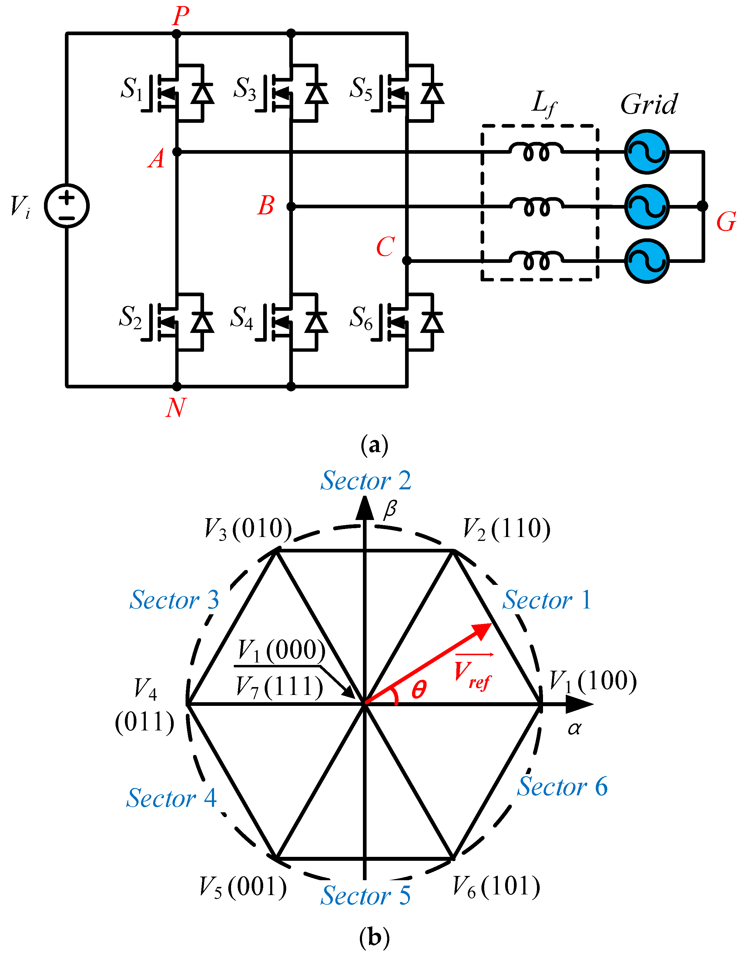
| Switching State | Bridge States | CMV Value |
|---|---|---|
| M0 | 000 | 0 |
| M1 | 100 | VPN/3 |
| M2 | 110 | 2VPN/3 |
| M3 | 010 | VPN/3 |
| M4 | 011 | 2VPN/3 |
| M5 | 001 | VPN/3 |
| M6 | 101 | 2VPN/3 |
| M7 | 111 | VPN |
| Topology | Component Count | Modulation Index | Boost Factor | CMV | Characteristic | ||||
|---|---|---|---|---|---|---|---|---|---|
| S | D | C | L | Advantage | Disadvantage | ||||
| Figure 4a [42] | 7 | 0 | 0 | 7 | 0 to 1 | 1 | VPN/3 |
|
|
| Figure 4b [45] | 8 | 0 | 0 | 0 | 0 to 1 | 1 | VPN/3 |
|
|
| Figure 4c [46] | 8 | 2 | 3 | 0 | 0 to 1 | 1 | VPN/3 |
|
|
| Figure 4d [47] | 8 | 0 | 0 | 0 | 0 to 1 | 1 | VPN/3 |
|
|
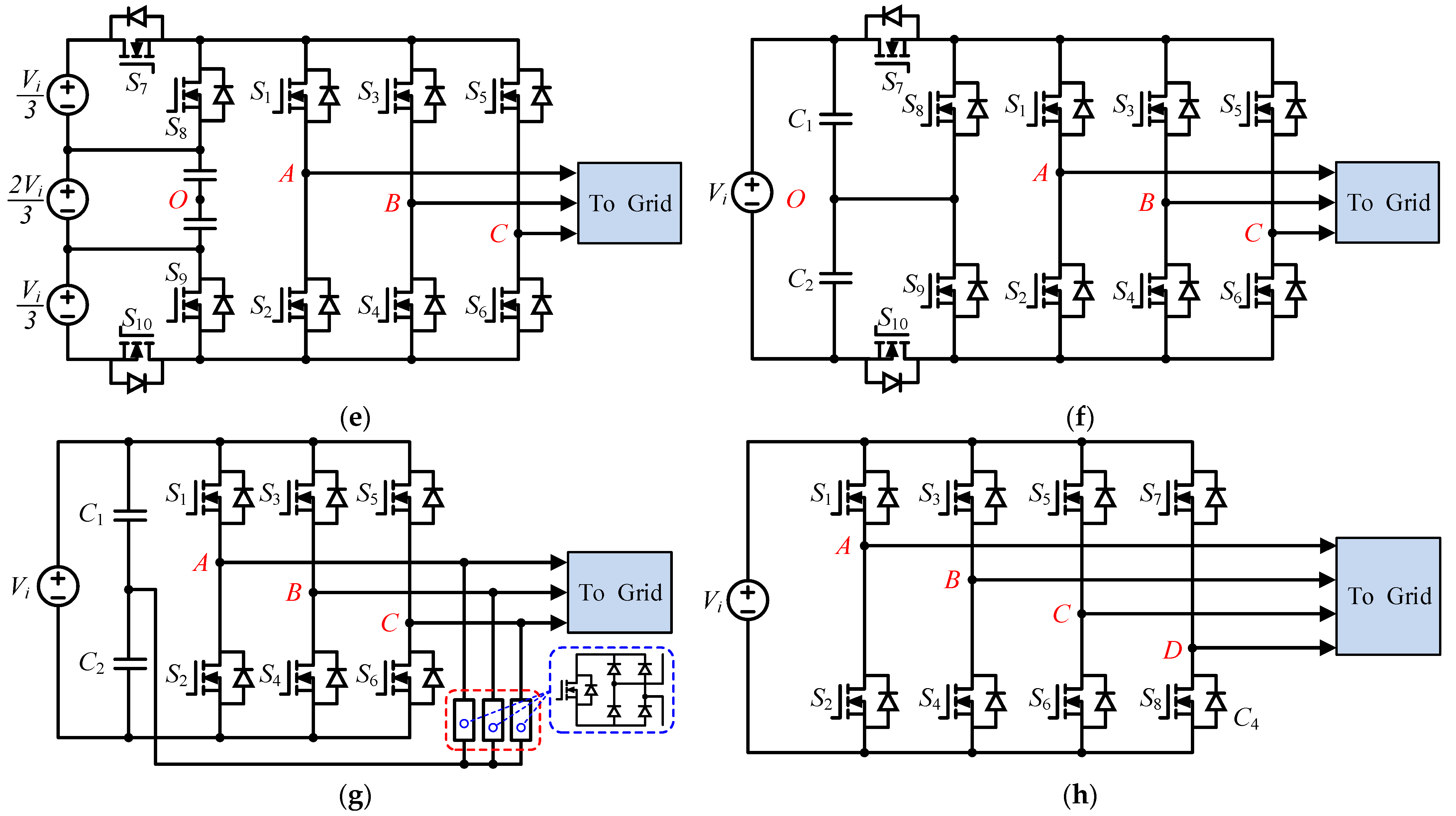
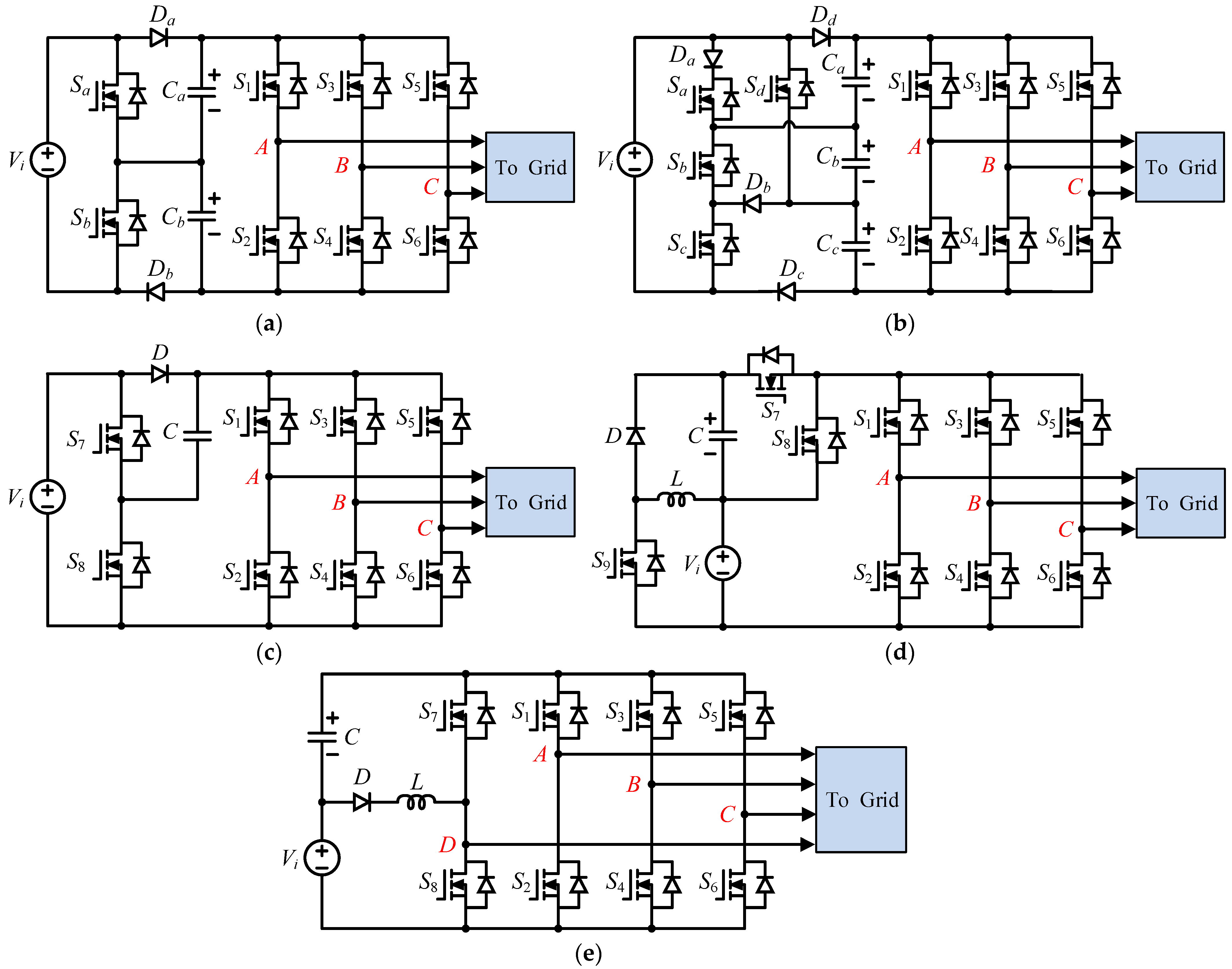
| Figure 4e [48] | 10 | 0 | 2 | 0 | 0 to 1 | 1 | 0 |
|
|
| Figure 4f [49] | 10 | 0 | 0 | 0 | 0 to 1 | 1 | 0 |
|
|
| Figure 4g [50] | 9 | 12 | 2 | 0 | 0 to 1 | 1 | 0 |
|
|
| Figure 4h [51] | 8 | 0 | 1 | 1 | 0.66 to 1 | 1 | 0 |
|
|
| Figure 5a with DSVM [53] | 8 | 2 | 2 | 0 | 0 to 1 | 2 | VPN/3 |
|
|
| Figure 5a with NSSVM [53] | 8 | 2 | 2 | 0 | 0.66 to 1 | 2 | VPN/6 |
|
|
| Figure 5a with RSSVM [53] | 8 | 2 | 2 | 0 | 0 to 0.57 | 2 | 0 |
|
|
| Figure 5b [54] | 10 | 4 | 3 | 0 | 0 to 1 | 3 | 0 |
|
|
| Figure 5c [55] | 8 | 1 | 1 | 0 | 0 to 1 | 1 or 2 | VPN/3 |
|
|
| Figure 5d [56] | 9 | 1 | 1 | 1 | 0 to 1 | 2 | VPN/3 |
|
|
| Figure 5e [57] | 8 | 1 | 2 | 2 | 0 to 1 | 2 | 0 |
|
|
| Topology | Component Count | Modulation Index | Boost Factor | CMV | Characteristic | ||||
|---|---|---|---|---|---|---|---|---|---|
| S | D | C | L | Advantage | Disadvantage | ||||
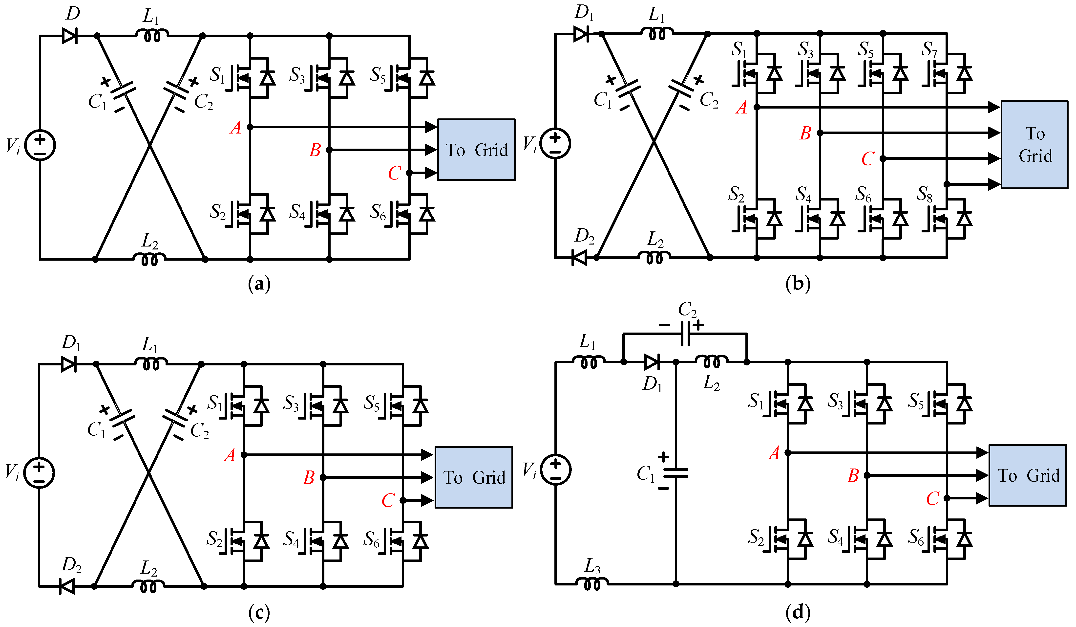
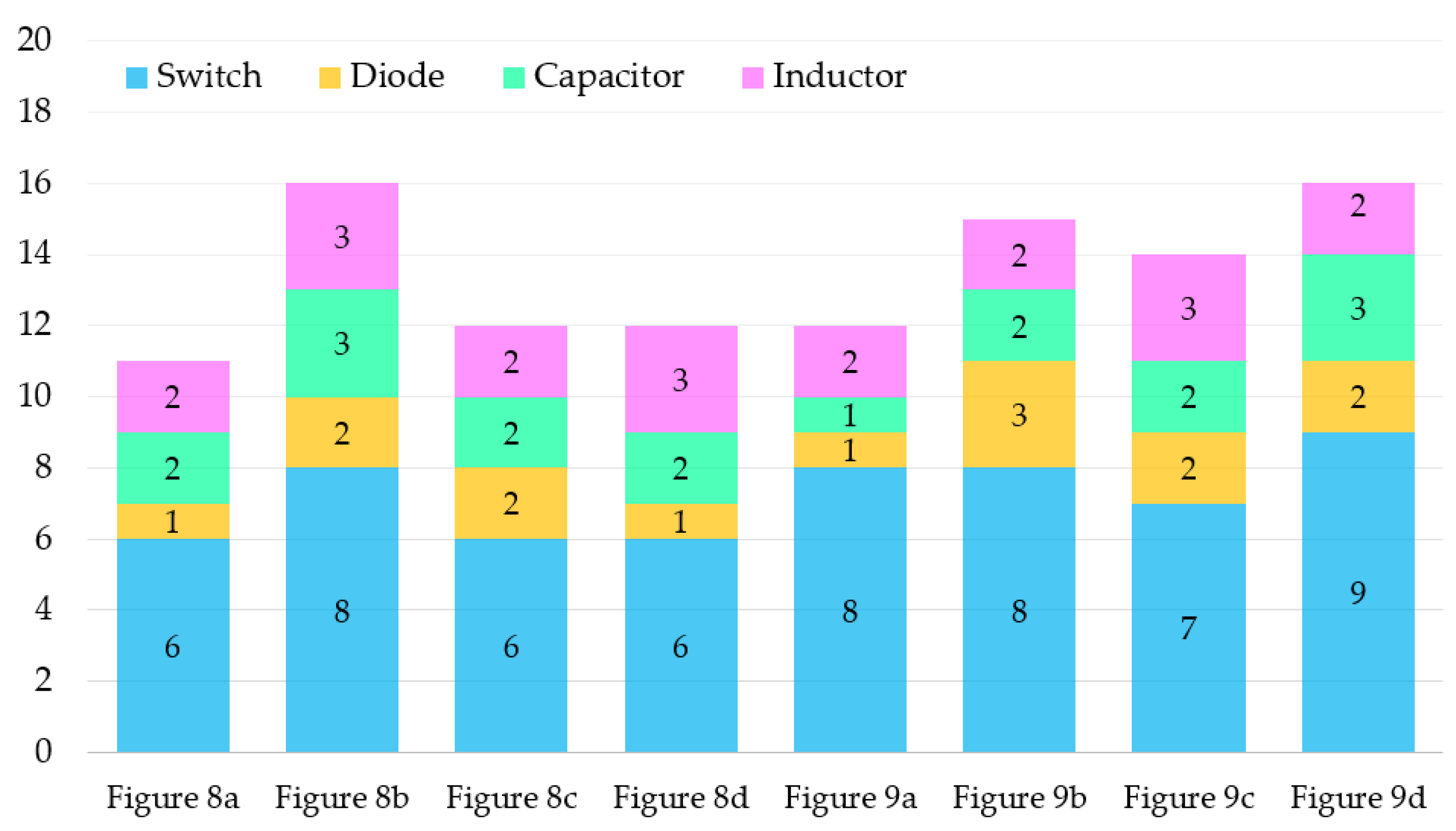
| Figure 8a [71] | 6 | 1 | 2 | 2 | 0.66 to 1 | 1/(1 − 2D) | VPN/3 |
|
|
| Figure 8b [73] | 8 | 2 | 3 | 3 | 0 to 1 | 1/(1 − 2D) | 0 |
|
|
| Figure 8c [74] | 6 | 2 | 2 | 2 | 0 to 0.57 | 1/(1 − 2D) | 0 |
|
|
| Figure 8d [76] | 6 | 1 | 2 | 3 | 0 to 0.57 | 1/(1 − 2D) | 0 |
|
|
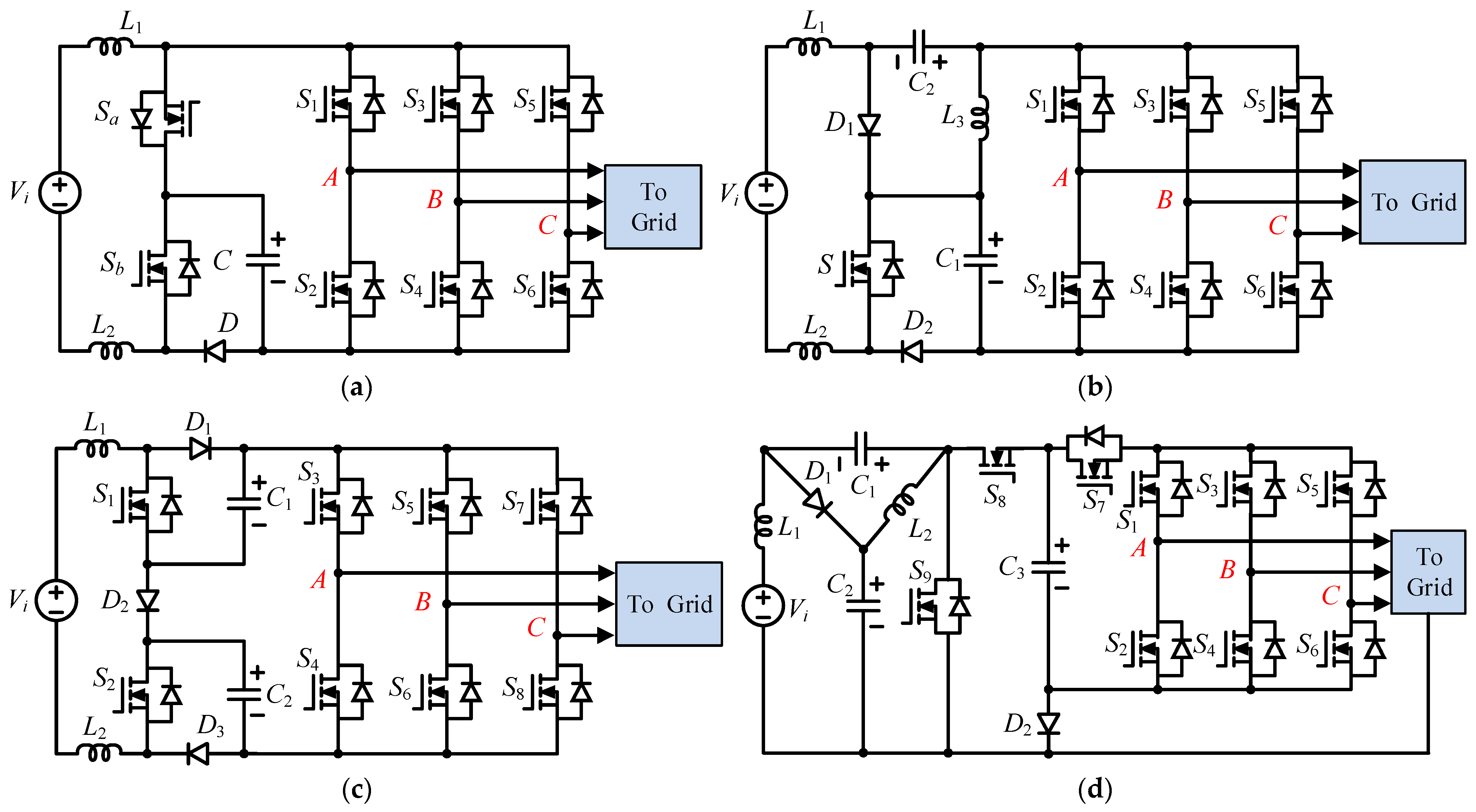
| Figure 9a [80] | 8 | 1 | 1 | 2 | 0 to 1 | 1/(1 − 2D) | VPN/3 |
|
|
| Figure 9b [81] | 8 | 2 | 2 | 2 | 0 to 1 | 2/(1 − 3D) | VPN/6 |
|
|
| Figure 9c [82] | 7 | 2 | 2 | 3 | 0.66 to 1 | 1/(1 − 3D + D2) | VPN/3 |
|
|
| Figure 9d [83] | 9 | 2 | 3 | 2 | 0 to 1 | 1/(1 − 2D) | 0 |
|
|
Publisher’s Note: MDPI stays neutral with regard to jurisdictional claims in published maps and institutional affiliations. |
© 2022 by the authors. Licensee MDPI, Basel, Switzerland. This article is an open access article distributed under the terms and conditions of the Creative Commons Attribution (CC BY) license (https://creativecommons.org/licenses/by/4.0/).
Share and Cite
Duong, T.-D.; Nguyen, M.-K.; Tran, T.-T.; Vo, D.-V.; Lim, Y.-C.; Choi, J.-H. Topology Review of Three-Phase Two-Level Transformerless Photovoltaic Inverters for Common-Mode Voltage Reduction. Energies 2022, 15, 3106. https://doi.org/10.3390/en15093106
Duong T-D, Nguyen M-K, Tran T-T, Vo D-V, Lim Y-C, Choi J-H. Topology Review of Three-Phase Two-Level Transformerless Photovoltaic Inverters for Common-Mode Voltage Reduction. Energies. 2022; 15(9):3106. https://doi.org/10.3390/en15093106
Chicago/Turabian StyleDuong, Truong-Duy, Minh-Khai Nguyen, Tan-Tai Tran, Dai-Van Vo, Young-Cheol Lim, and Joon-Ho Choi. 2022. "Topology Review of Three-Phase Two-Level Transformerless Photovoltaic Inverters for Common-Mode Voltage Reduction" Energies 15, no. 9: 3106. https://doi.org/10.3390/en15093106
APA StyleDuong, T.-D., Nguyen, M.-K., Tran, T.-T., Vo, D.-V., Lim, Y.-C., & Choi, J.-H. (2022). Topology Review of Three-Phase Two-Level Transformerless Photovoltaic Inverters for Common-Mode Voltage Reduction. Energies, 15(9), 3106. https://doi.org/10.3390/en15093106