1. Introduction
Large-scale integration of renewable energy sources (RES) in energy systems is challenging because of several operational obstacles. To name a few, one may start from technical issues such as, control and management because of the intermittent supply from solar and wind systems and then, one may continue to issues related to social acceptance, legal and economic issues about new business models [
1,
2]. As regards the electricity grids, by large-scale integration of RES, the electrical power distribution grid shows strong de-centralized characteristics that directly correlated to other technologies such energy storage systems (ESS) [
3] and flexible loads such as electric vehicles (EVs) [
4,
5]. Nowadays, customers have the opportunity to produce, consume, store, export and import energy. Consequently, they have an active role in the electrical power grid [
6,
7]. Energy storage, either as part of behind the meters applications [
8] or as part of the secondary distribution network [
9], offers several advantages for power peak saving, grid efficiency, and security of supply. This is an important contribution for the electricity grid because it involves releasing resources into the power systems value chain since they defer in future possible infrastructure reinforcement. In addition, the combination of ESS to demand response (DR) technology and distributed generation (DG) from RES further strengthens the electricity grids by adding flexibility in load energy management. In such cases, optimal energy management is achieved in terms of constraints for improved efficiency, reduced operation costs, and/or CO2 emissions [
10].
Energy storage involving DG and power peak shaving is extensively investigated in many aspects. The study presented in [
11] investigated power peak shaving and the effects of ESS and PV production aiming to maximize self-consumption. Other studies focus on control and incentive schemes for power peak shaving and demand management [
12,
13]. Investigation about the optimal sizing of battery storage for residential power peak shaving is conducted in [
14] taking into account low and high electricity usage and electric space heating. The algorithm by S. Favuzza et al. in [
15] to completely flatten consumer’s load profile requires massive storage capability that could be techno-economically unfeasible to be adopted. It is therefore important to understand using real data and customers’ behavior the applicability of any relevant proposal. Jaser Sa’ed et al. [
16] present an optimization methodology that provides a holistic approach for dimensioning a BESS based on the applicable peak charging energy contracts. Bwo-Ren Ke et al. in [
17] provide a procedure for sizing a BESS that operates in line with DG. This approach clearly provides benefits as far as the energy bills are concerned, but these benefits are rather produced from the solar system than the BESS per se. Enrique Lobato et al. developed an algorithm for peak shaving using energy storage for isolated networks in [
18]. Roozbeh Karandeh et al. [
19] investigated peak shaving through BESS for charging applications. They demonstrate the impact of the storage to the capability of a complete system to provide smooth load profiles even under intense operation periods.
In this paper, two distinct operational business models of BESS are examined in relation to the design and the implementation of the systems as well as in relation to the incentives of the relevant business models. In the first model, the BESS is aggregated at the transformer’s low-voltage (LV) side and operates as a single unit that covers the total load of the end users as seen by that point in the grid. In the second model, a BESS placed at LV-side but at the end users is considered that operates as distributed system aiming to cover the end-user at which it belongs. Both models take into consideration the customers’ behavior via electrical power demand extended measurements and prices for the energy and the batteries as investment cost. In addition, the paper contributes to the debate about how solar PV power might be large-scale integrated by avoiding LV grid hosting capacity violation by using BESS either in aggregated or in a more distributed concept.
The main contributions in this paper are:
- (i)
The electrical power consumption patterns of a real residential LV feeder were measured and analyzed. The total power at the LV side was measured and compared to the corresponding measurements at the load side via the end users’ meters.
- (ii)
The operability of local energy transaction is investigated between residential customers of the same type which present different consumption habits.
- (iii)
Based on the measurements, an aggregated at the LV side of transformer and a distributed to the load side BESS are computed and examined aiming to assess the factors that incentivize the installation of BESS including the economic viability and profitability.
The paper is organized as follows.
Section 2 presents the residential feeder and the analysis of the measurements.
Section 3 presents the computations for the business models under consideration. Discussion of the finding is presented in
Section 4 and the paper is concluded in
Section 5.
2. Feeder Description and Measurements
In this section, the measurements of the electrical power consumption patterns for the residential customers at the utility LV transformer side and at the load side are presented.
2.1. Description of the System
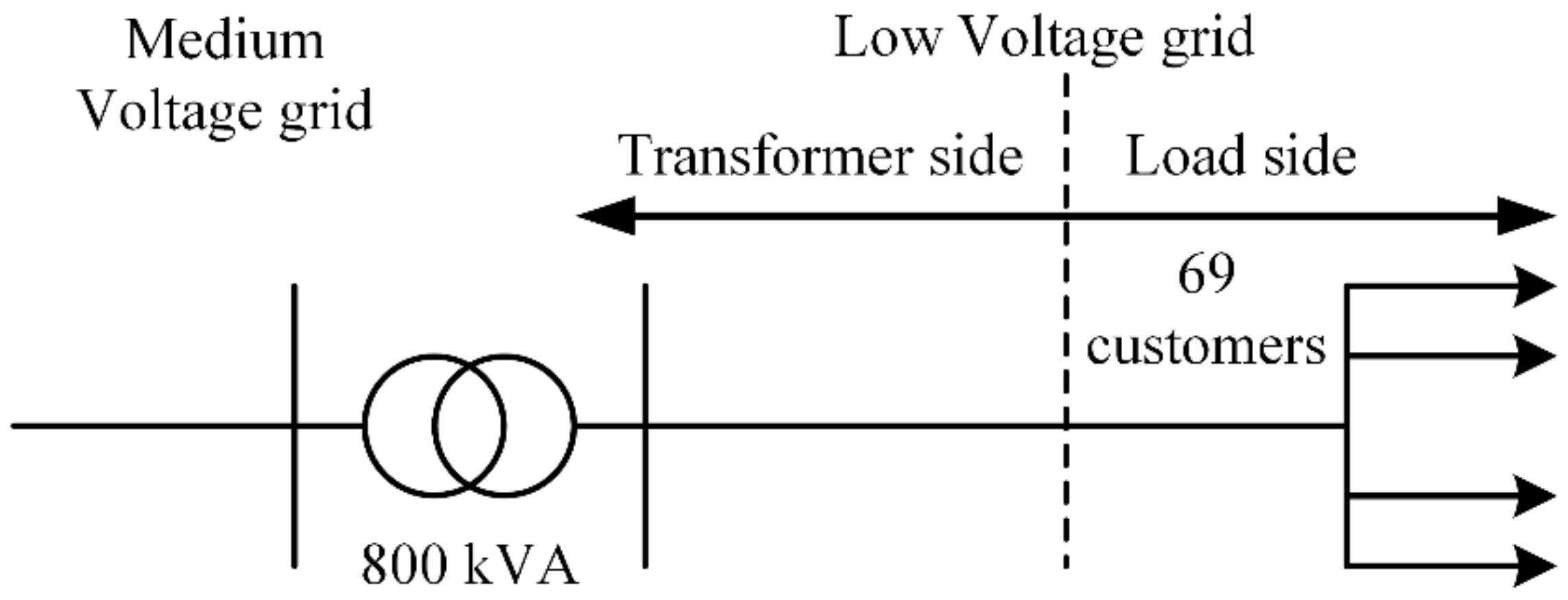
The LV residential feeder in
Figure 1 at Karlstad city in Sweden is examined in this paper. An 800 kVA distribution transformer supplies 69 customers, from which 68 consist of typical residencies and 1 represents a collection rail for lamp posts. The regional distribution system operator (DSO) provided to us access to the energy meters of the network in order to collect data of the consumed power during one year, from 1 March 2018 to 28 February 2019. Hourly measured data were available and the measurements have been collected and processed accordingly in the form of lists. Due to privacy policy reasons, the measurement are presented in the form of graphs in the next sections.
2.2. Measured Data at Transformer Side
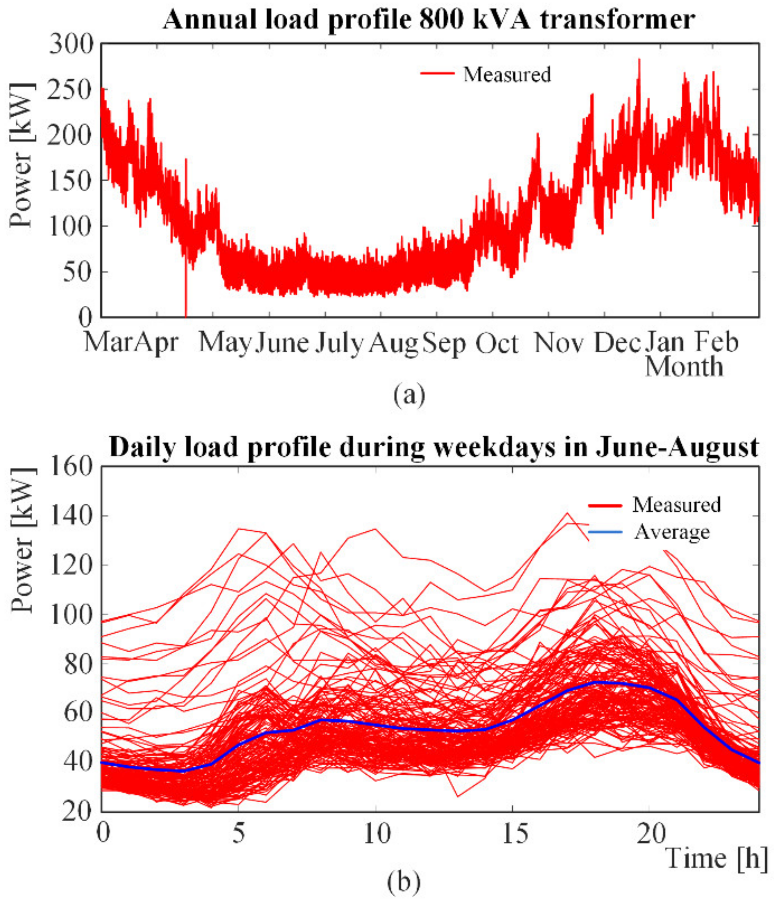
The collected data at the transformer side during one year are shown in the
Figure 2. In
Figure 2a, the red line represents the measured consumption during one year and one can observe a decreased energy consumption during spring and summer in comparison to autumn and winter seasons. This is due to the higher temperature of about 15–25 °C when there is no increased need for space heating. The power peak varies between 80–290 kW depending on the season. Moreover, one can observe that during May to mid-September there are no high monthly variations of the power consumption as those in comparison to the period between mid-September to end-April. For example, during November the lowest and the highest peaks are about 75 kW and about 240 kW, respectively while in June they are about 25 kW and 80 kW, respectively. In
Figure 2b the red lines correspond to the measured consumption and the blue line presents the average consumption from June to August during weekdays. The average consumption is calculated by summation of the measured consumption values at the same time in each day for all days from June to August over the number of the measured values. By following the blue line that shows the average consumption, there is a low peak in the morning around 08:00 having value about 60 kW and one higher peak in the evening around 18:00 having value about 75 kW.
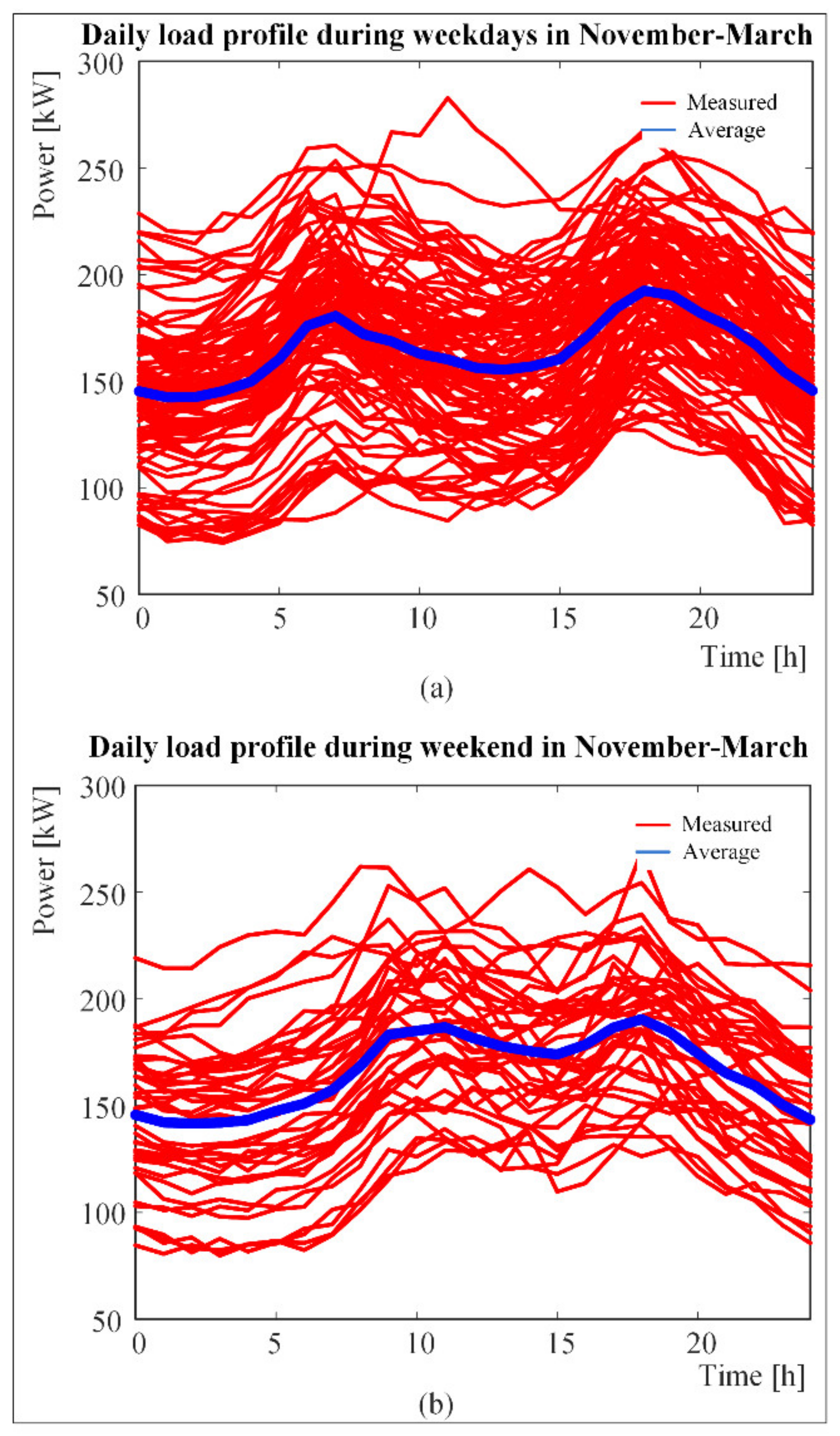
Figure 3 presents the consumption patterns for the period between November to end-February during weekdays and weekends. During weekdays and by reading the blue average line in
Figure 3a, one can observe two distinct highest power peaks. The first is in the morning around 07:00 having a value about 175 kW and the second is in the evening around 2:00 having value about 190 kW. During weekends in
Figure 3b, by reading the average blue line, one can observe that the highest power peaks reach the same levels as those during the weekdays, the evening highest peak is about 20:00. However, the highest peak in the morning is shifted about 10:00 in comparison to that in weekdays.
The above analysis of the measured consumption patterns reveal that except of the high seasonal variation as is presented in
Figure 2a, the consumption patterns from the transformer side reveal strong similarities during particular seasons. As such, the transformer does not experience loading conditions that have high differences and consequently, a technically and economically viable aggregated BESS system for energy storage and peak shaving could be computed suitable to cover all customers treated as one aggregated load.
2.3. Measured Data at the Load Side
The individual consumption patterns for each customer have been measured.
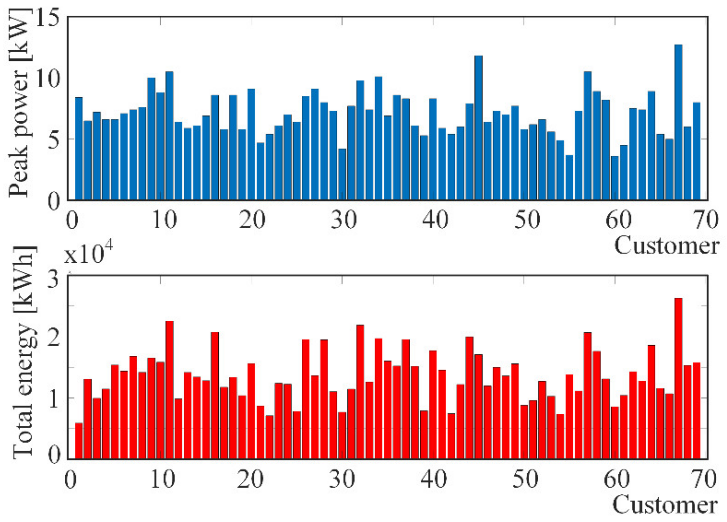
Figure 4 presents the power peak and the total power consumption of the residential area under examination. The peak power varies between 3.6 kW to 12.7 kW while the annual energy consumption varies from 9 MWh to 26.3 MWh.
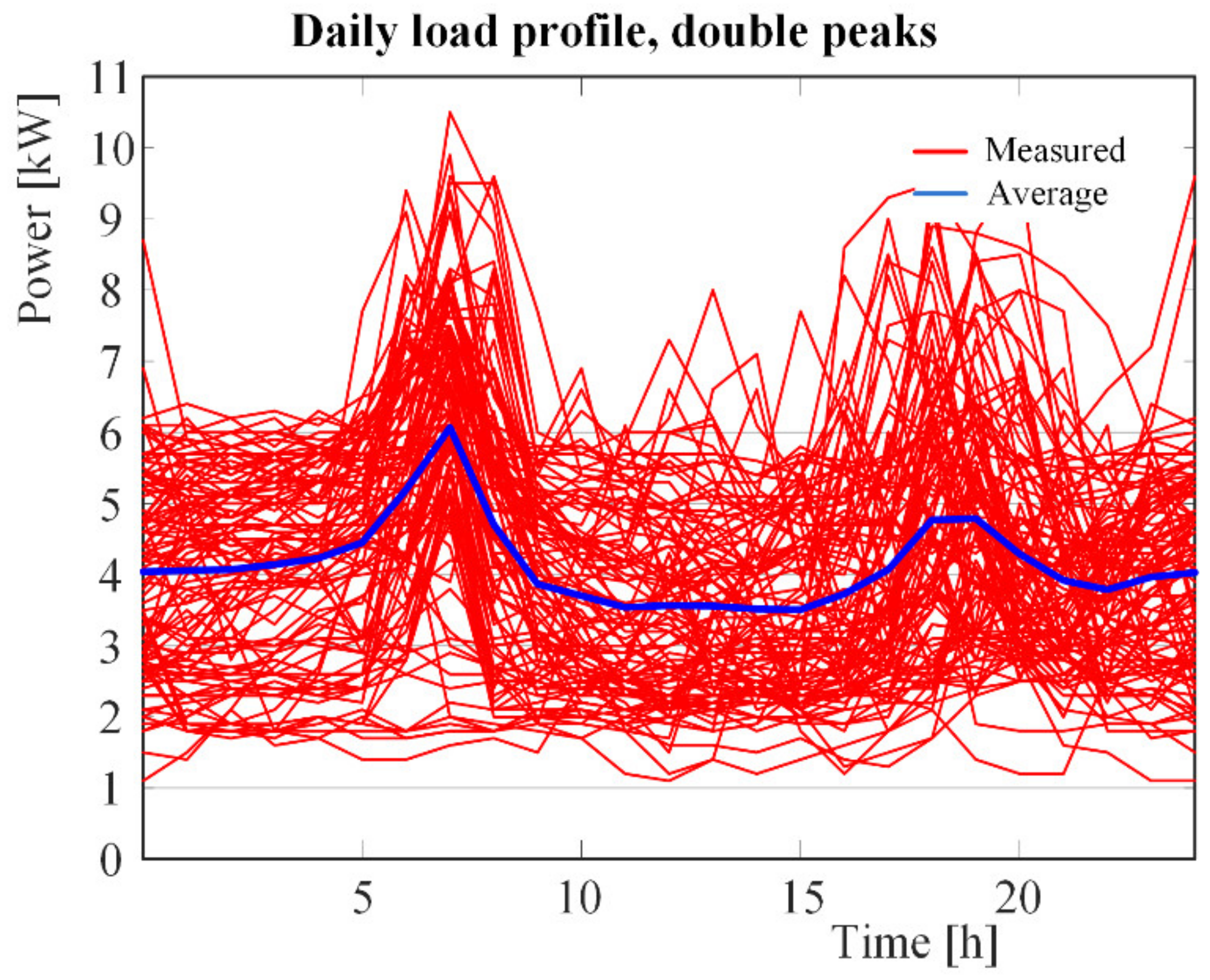
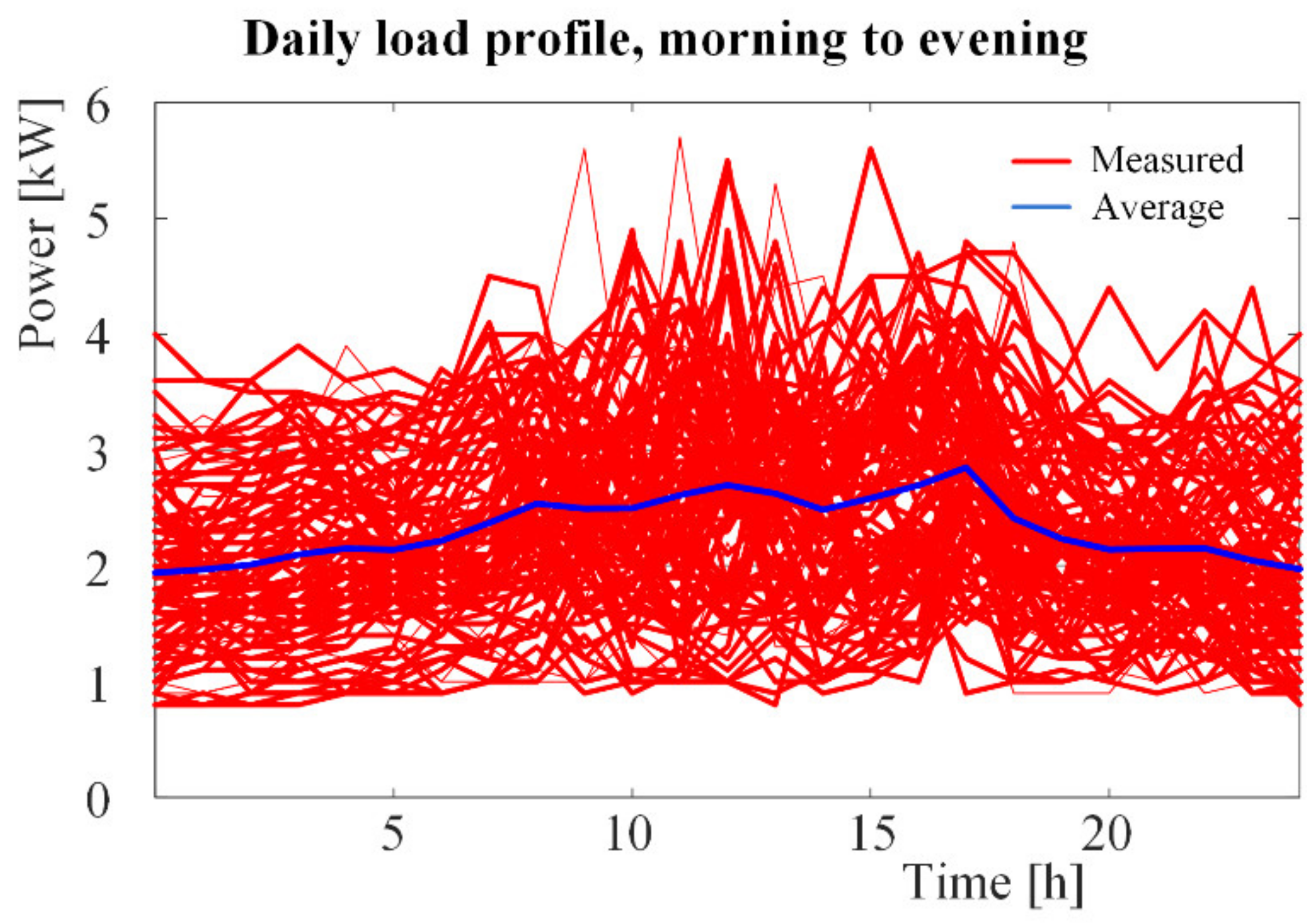
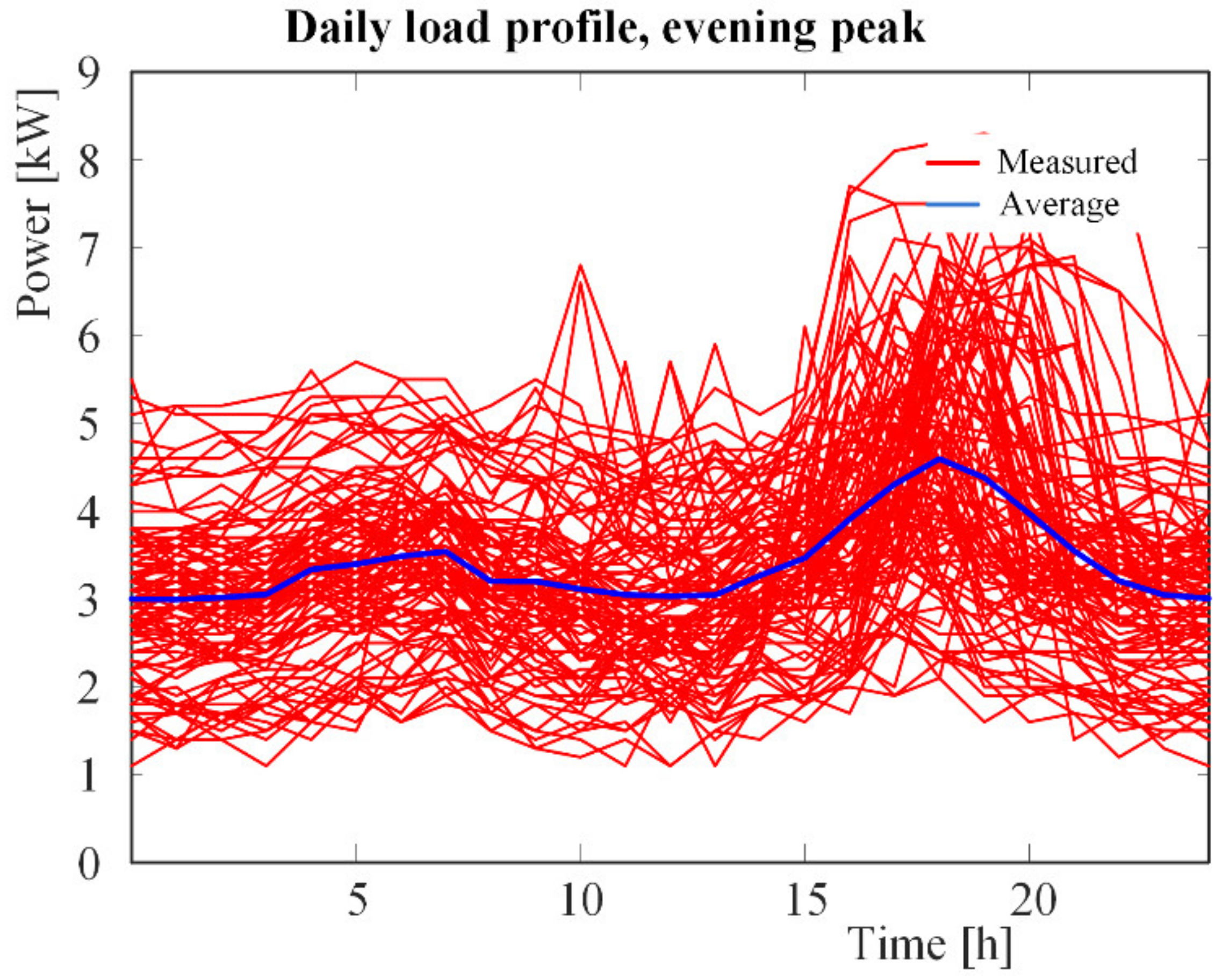
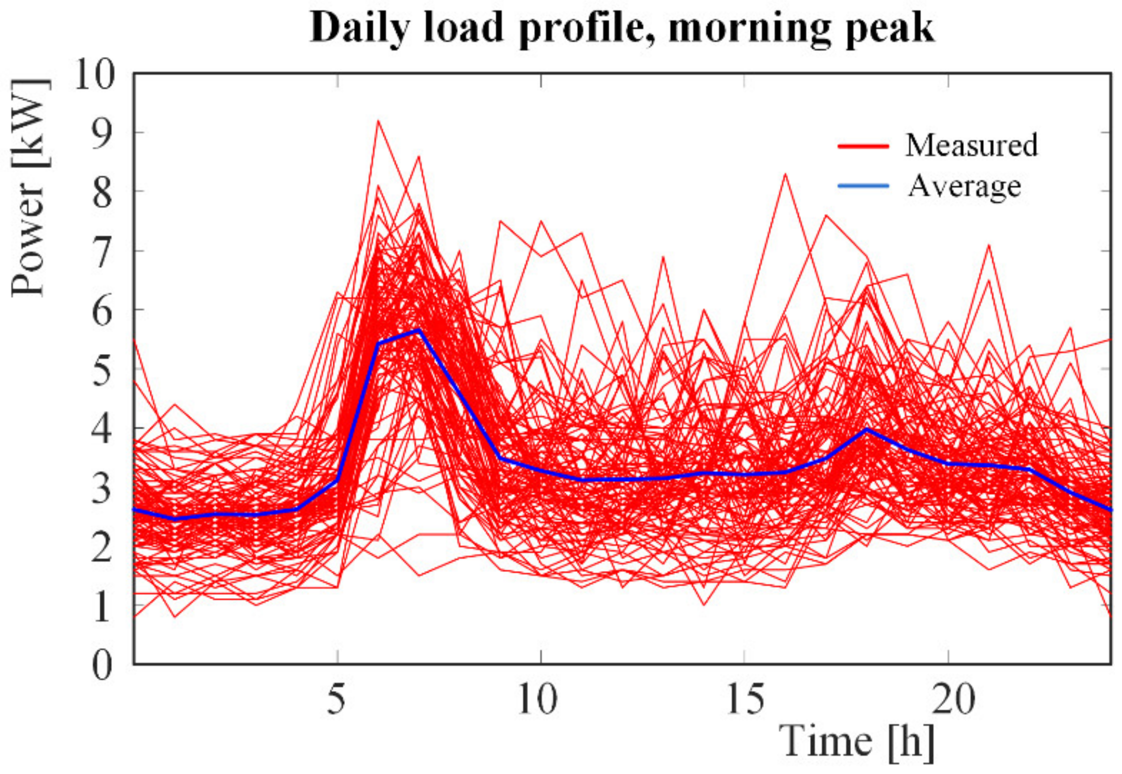
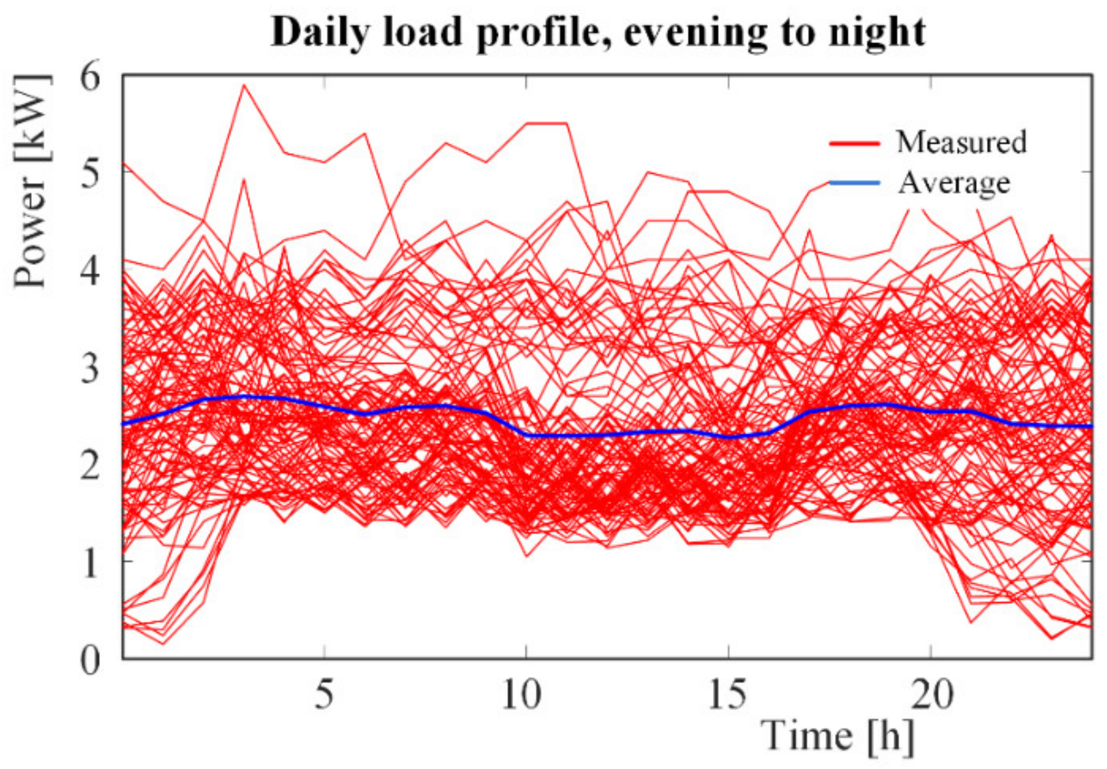
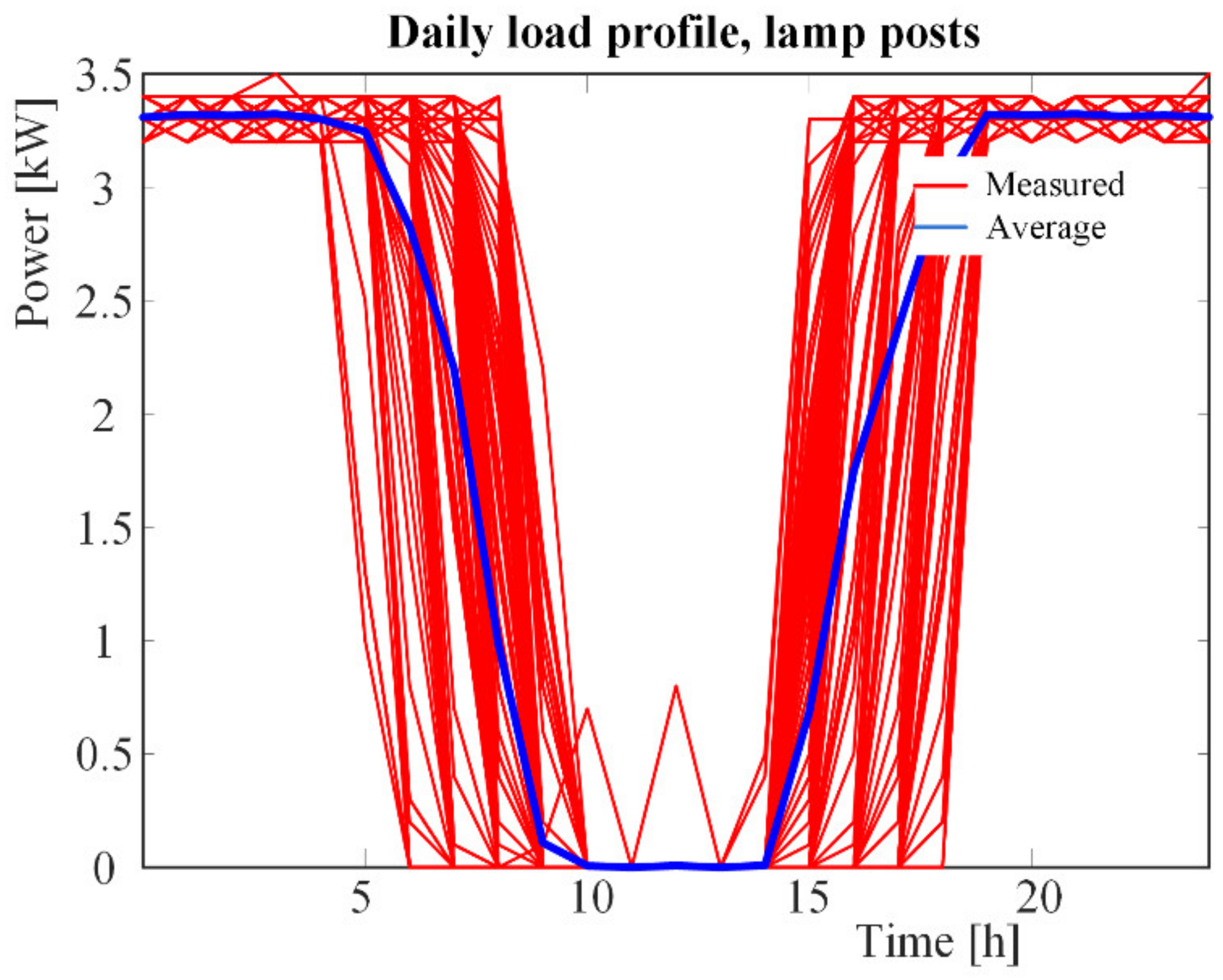
As the highest power output occurs during the winter months, the residential consumption patterns were further analyzed between November and end-February because during these months there are additional fees from the regional DSO called as “high-charge fees”. The analysis reveal six consumption patterns. There are five different residential consumption patterns during weekdays and are presented in the
Figure 5,
Figure 6,
Figure 7,
Figure 8 and
Figure 9. They are categorized as double-peaks, day-evening peak, evening-peak, morning-peak, and evening-night peak. There is also one pattern that corresponds to outlets of lampposts in
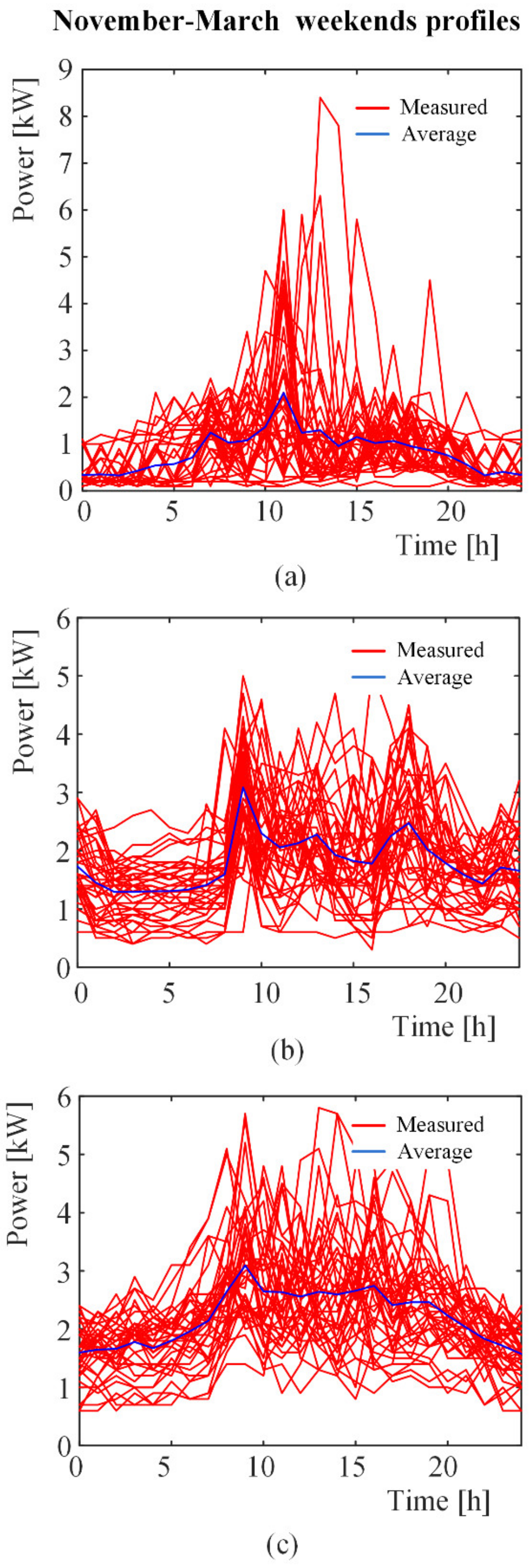
Figure 10. Among the above defined profiles of the 69 consumers, the 45% presented double-peaks and 39.1% presented day-evening peaks. The rest presented 8.7% evening-peak, 4.3% morning-peak, and 1.45% evening-night peak. The rest 1.45% corresponds to the lampposts. During weekends, there were not so many consumptions variations between the consumers. The corresponding consumption patterns are presented in
Figure 11. One may observe one highest peak in the morning to afternoon hours while there could be a lower peak in the evening hours.
The measured residential consumption patterns reveal that at load side, the patterns may show major differences mostly in weekdays rather than during weekends. Residential storage and peak-shaving, especially in the case where a customer has power production capabilities as prosumer, are case-by-case dependent. Hence, none may take for granted that energy storage should be conducted during night supposing that the energy demands are lower. Analysis of the individual consumption pattern for each prosumer is necessary in order to size an economically viable residential BESS. In addition, the presence of battery storage in DC applications may have an important share in future installation because of their advantages in relation to AC solutions [
20]. Another important finding from the analysis of the measurements is that the customers who bring energy production from RES and residential BESS may participate in peer-to-peer (P2P) energy trading because their peak demands appear at different times during a 24 h period especially during weekdays. This kind of energy management schemes for optimal trading based on market tariffs is considered an important topic in transactive microgrids [
21,
22].
3. Simulation Results for an Aggregated and for a Distributed BESS Configuration
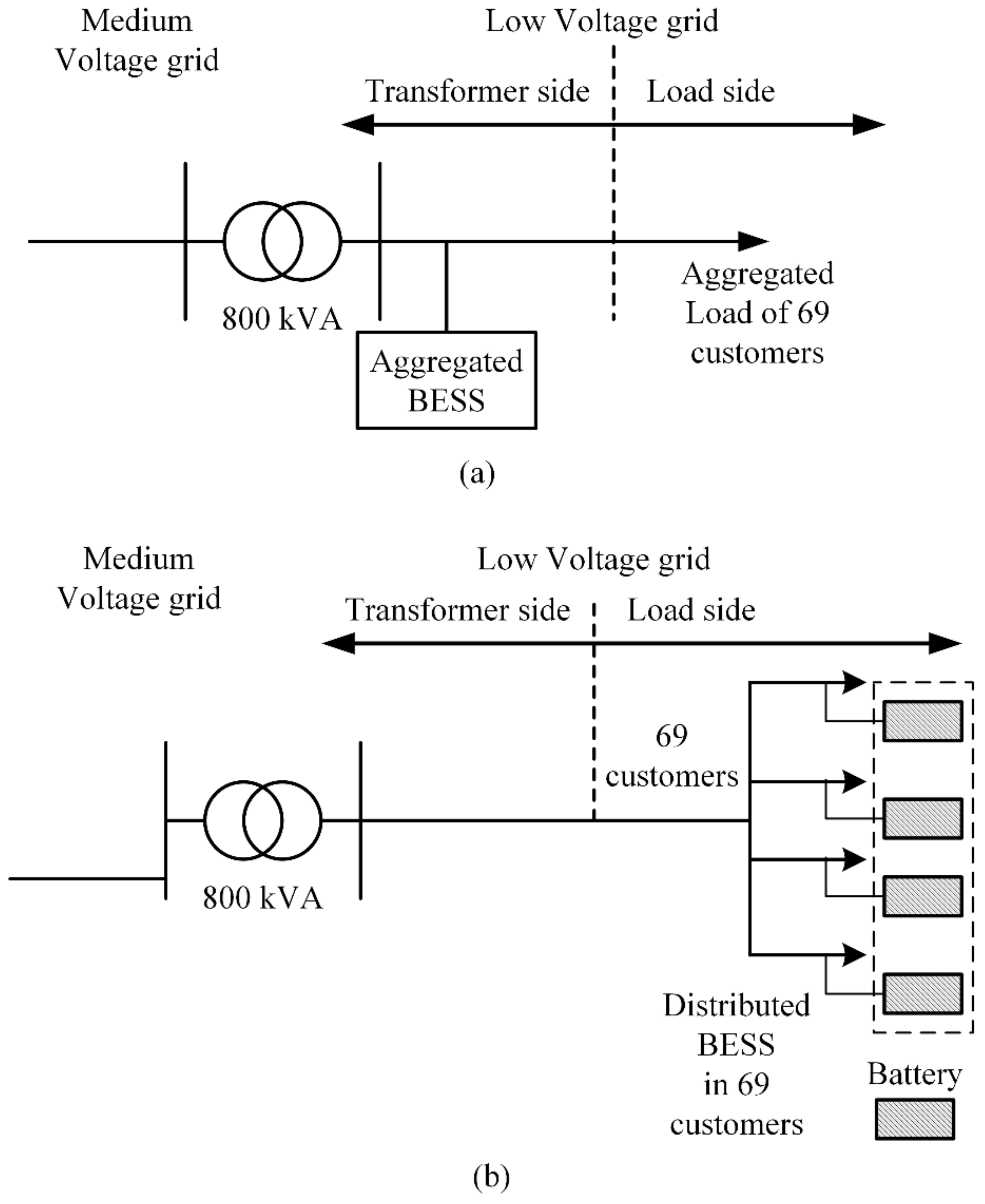
In this section, computations about two scenarios of BESS are presented as shown in
Figure 12. In the first scenario, as shown in
Figure 12a, the 69 customers are considered as an aggregated load for which an aggregated BESS at the transformer LV side aims to support the transformer’s loading conditions. In the second scenario, as shown in
Figure 12b, a distributed BESS allocated to each customer that also aims to support the transformer’s loading conditions is presented. The BESS under development aims to sustain the transformer during the periods of high load demand rather than during the whole year. As such, the presented investigation is focused in the periods of high power profile. The first period is during March 2018 and the second period starts at the beginning of December 2018 and closes in the end of February 2019, which is mostly used for the discussion of the findings. Preliminary computations have been conducted in order to explore the correlation of the threshold limits of the maximum power above which reduction of the power peak is intended to relief the grid, the corresponding batteries sizes, and the associated profitability of the investment. As expected, a lower threshold limit leads to a wider time window for peak shaving for lower profiles which in turn, results in a larger battery size and thus, in a more expensive investment and more years of investment. However, each BESS design presents different capabilities and particularities because the one coordinates to the transformer aggregated load and the associated costs while the other coordinates to the end-users loads and charging fees.
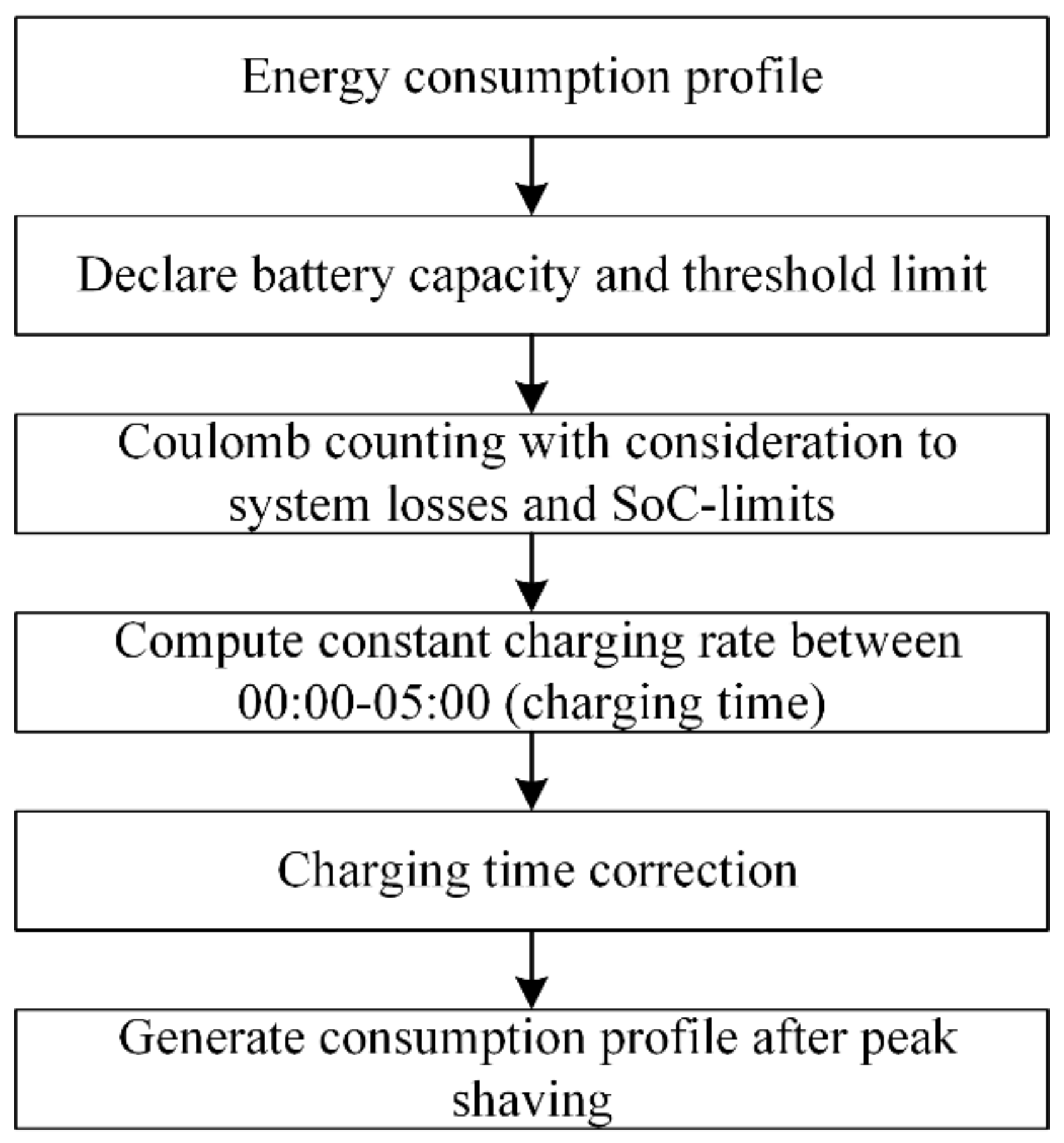
The BESS computations are performed by using the flowchart and the conditions described in the
Appendix A. Additional explanations on the calculation of several quantities are described further on. In this section, simulation results such as the state of charge (SoC), the depth of discharge (DoD), and the C-rate as well as discussions and challenges regarding financial calculations are presented. Specifically, in the simulation results of the scenarios sections, representative results are highlighted for the reduction of the power peak, the SoC, the DoD, the charging and discharging rates and cycles for the above defined time window. In the economic calculations sections, the profitability of the designs is explored aiming to highlight its dependence from the charging costs, the initial investment of the batteries, and the gain because of the cost reduction due to power peak shaving.
As regards the batteries, the SoC varies between 30% and 75% to protect their state of health, the efficiency is considered 100% for both charging and discharging operations as well as ageing effect and package degradation are not taken into account. The charging and discharging rates are constant supposing constant current charging mode as appears in the algorithms of real lithium-ion batteries in the above mentioned SoC range. Improved assumptions on the aforementioned parameters should be adopted in a detailed energy management optimization investigation in which objectives such as minimization of systems losses, maximization of customers’ comfort and/or satisfaction levels and the maximization of profit for each stakeholder are important. The charging times are set from midnight to 05:00 h in the morning. The charging and discharging rates are considered to be constant and correspond to typical values for lithium-ion batteries for these applications and the values are mentioned in the results presentation sections in each case separately. Finally, the analysis is performed in a 15 min time interval for which linear interpolation is used to create intermediate to the hourly measured time-series data points for the computations.
As regards the economic calculations, the cost of such investments depends on the installation costs such as equipment (e.g., batteries, cables, management systems, software for monitoring etc.,), maintenance costs as well as human-hours costs for the technicians. Since, this is not a strict techno-economic investigation, as basic investment the cost of batteries is assumed that is the product of the battery capacity selected in kWh and the battery price per kWh. Based on this, the payback time is calculated as the product of the basic investment and the savings per year. Then, the year of profit is the time left after the payback time until 20 years which is the selected lifetime of the batteries. Finally, the total profit is examined with respect to the years of profit.
3.1. Scenario 1: Aggregated BESS
In this section, simulation results and economic calculations are presented for the aggregated BESS. Such systems are under investigation from the regional DSO for grid support and energy management as part of the secondary distribution at the LV-side of the transformer.
3.1.1. Simulation Results of Scenario 1
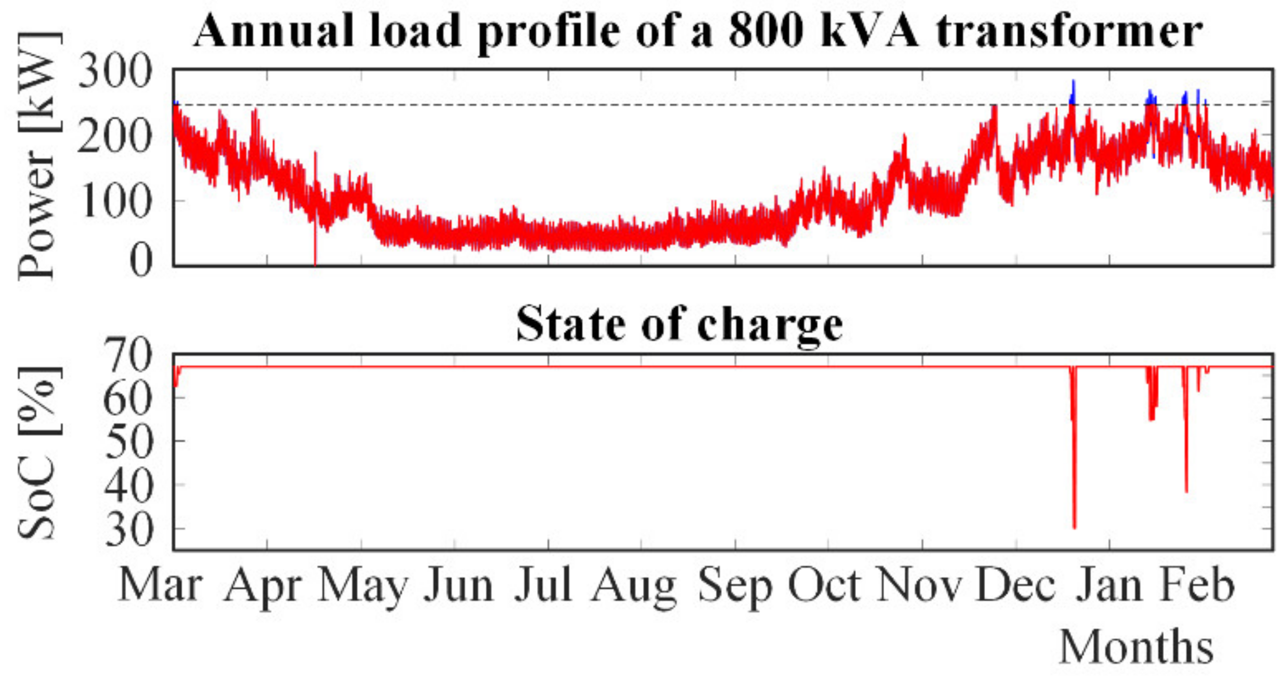
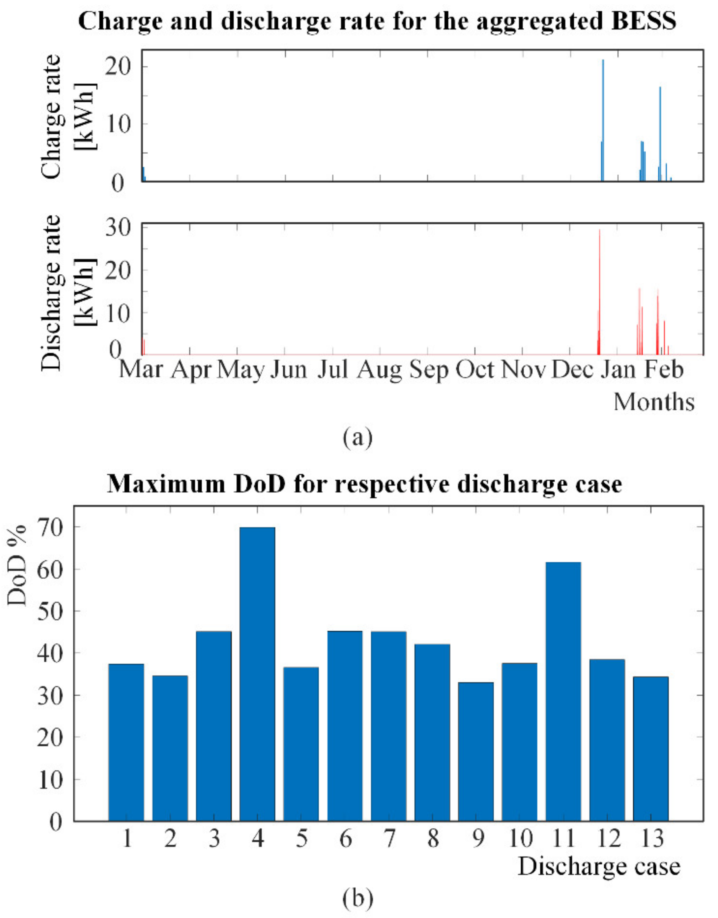
Figure 13 shows the reduction of the power peak at the transformer side. The maximum power output is 282.8 kW, the threshold limit is 246 kW, and capacity of the battery is 289 kWh. This leads to a reduction of the power peak about 13% (36.8 kW). During mid-March 2018 until mid-December 2018, the SoC remains constant at about 70% as a result of the computations during charge/discharge events at mid-March 2018. In this period, the transformer experiences low load needs as seen in the annual load profile while the investigation is focused in the period of higher load profile. The simulation settings yielded a maximum charging rate and discharging rate of 21.32 kWh and 29.49 kWh respectively, as shown in
Figure 14a. This corresponds to 0.074C and 0.102C for the C-rate, respectively.
Figure 14b shows the number of discharge cases in one year and the corresponding DoD for the discharging cases while, both charging and discharging rates during the operations of the battery are shown in
Figure 14a. In particular, one may observe that battery discharge occurs only for 13 days during the year in the period from December to March that leads to DoD variation of about 33–70%. To describe an example, discharge case 1 in
Figure 14b reaches to a DoD of about 38%, having discharging rate about 3 kWh as it is shown during March on the left side in
Figure 14a and SoC about 62% as it is shown during March on the left side in
Figure 13.
Further simulations have been conducted by lowering the threshold limit and increasing the capacity of battery. The results present qualitative similarities to those presented in
Figure 13 and
Figure 14 such as, higher levels of the power peak reduction at the transformer side, similar levels of the C-rates, and more days of discharge. However, these results should be investigated from an economic perspective in order to estimate their influence on the total investment. This investigation is presented in the next section.
3.1.2. Economic Calculations of Scenario 1
In this section, the total profit is calculated for the above presented aggregated at the transformer side BESS for increasing threshold limit from 246 kW onwards.
Table 1 shows the savings per year, the repayment period, and total profit depending on the reduction of the power peak and the battery price. The power charge per year reflect the highest power peak consumption cost and is calculated as the sum over one year (12 months) of the product of the corresponding fee and the value of the highest power peak consumption in each month. The variable charge per year reflects the total used energy cost in one year and is calculated as the product of the corresponding fee and the whole amount of energy in one year. Savings per year are calculated as the difference of the charges per year before and after reduction of the power peak by using tariffs as 194 SEK per kW and year for the power charges as well as 0.007 SEK per kWh for varying regional network charges as they have been taken from the regional transmission operator. Larger reduction of the power peak results in lower total profit because of the battery size and cost.
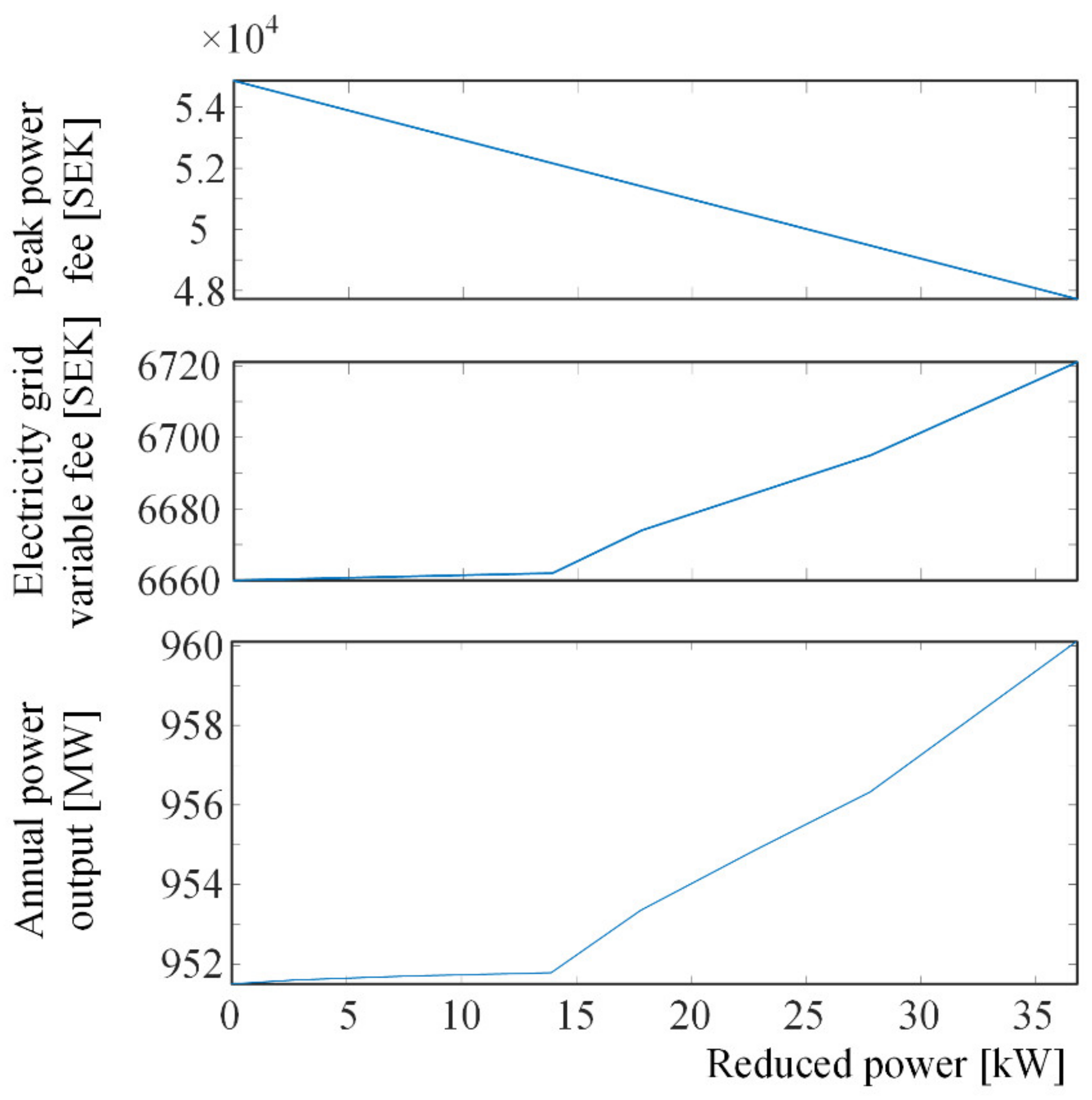
Figure 15 highlights that the annual peak power charge decreases linearly with reduced power peak, while the variable electricity grid charge stays at approximately the same level between 0 and 13.9 kW reduced power peak. Thereafter, the electricity grid variable fee rises almost linearly in relation to reduced power peak. Moreover, after 13.9 kW reduction of power peak, the total power output increases linearly in relation to reduced power.
The savings per year S
p with respect to the profit time T for battery price
$50/kWh is plotted in
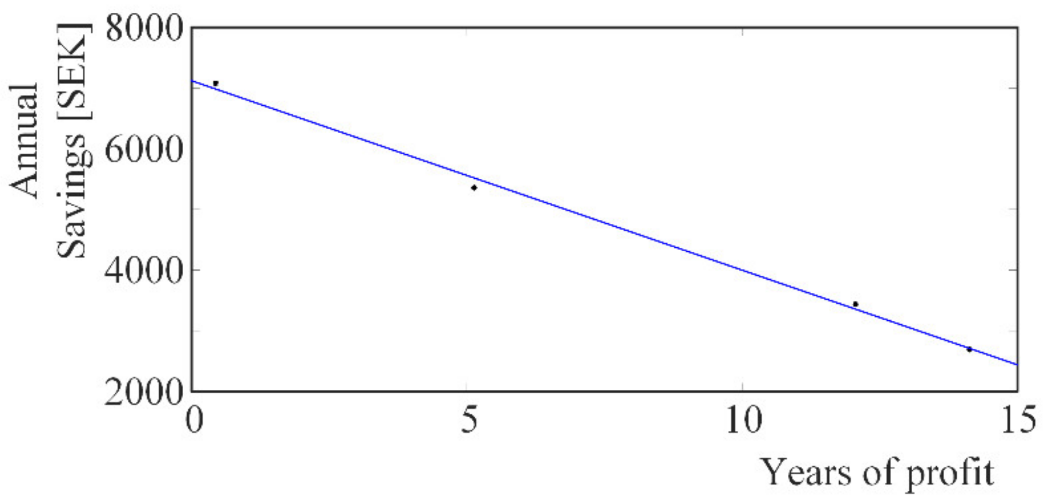
Figure 16. Profit time is the time left after the payback time and the battery’s lifetime, which is selected to be 20 years. MATLAB curve fitting toolbox has been used in order to compute the curve that best fits to the plotted points. The result is the linear expression
a = −312.2 SEK/year and b = 7121 SEK.
Total profit P
r is given by
By substituting (1) in (2), the total profit P
r shows a second-order dependence from the profit time T as
Figure 16.
Saving per year with respect to the years of profit supposing $50/kWh battery price.
Figure 16.
Saving per year with respect to the years of profit supposing $50/kWh battery price.
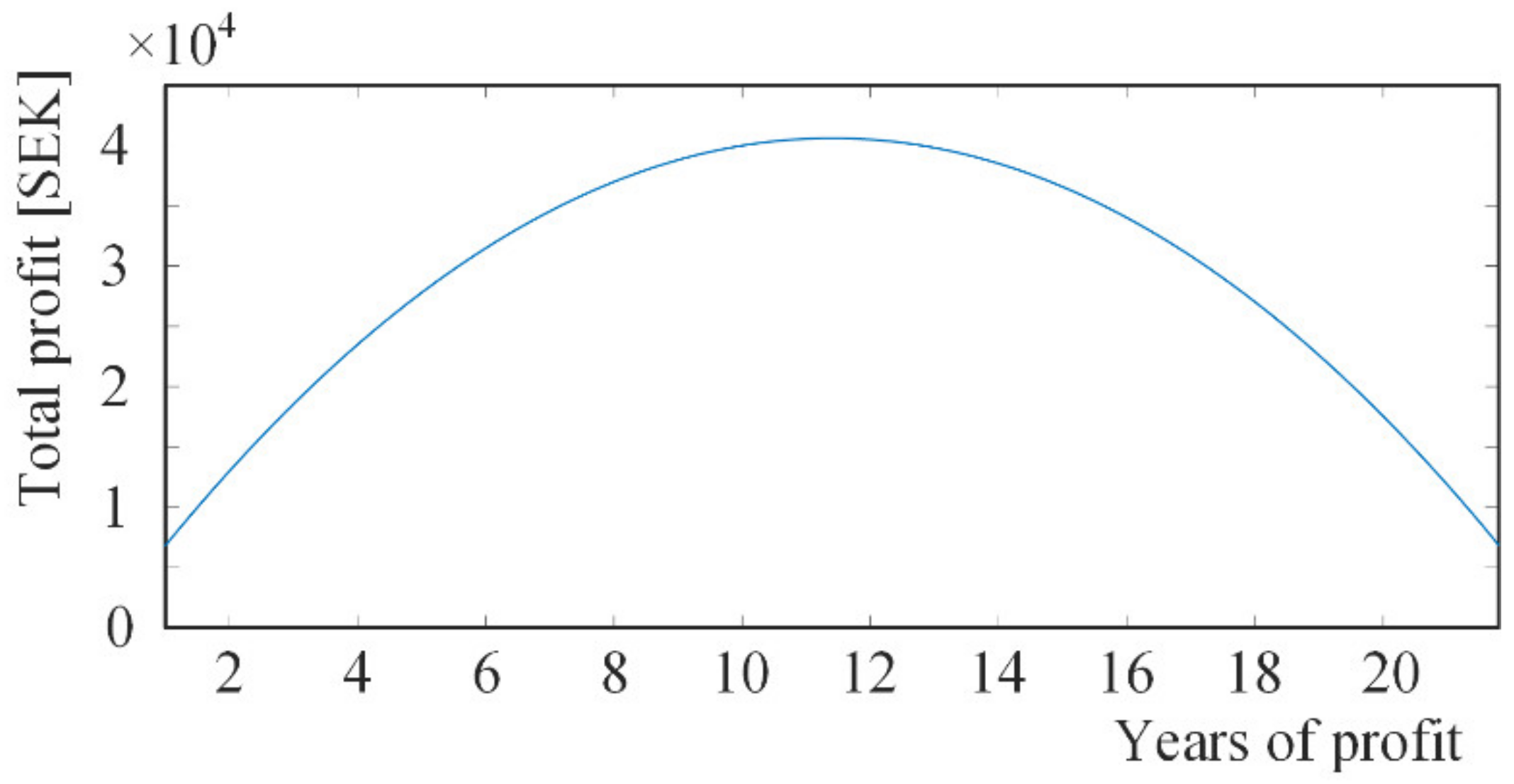
Figure 17 shows that the total maximum profit appears at 11.4 years. The profit period of 11.4 years corresponds to 3560 SEK in savings per year and the payback period of 8.6 years. Total profit is estimated at 40,584 SEK that means a reduction of 17.8 kW and battery capacity of 57 kWh. The reason why a reduction of 13.9 kW does not provide maximum profit is because the relationship between savings per year and the profit period is not completely linear.
3.2. Scenario 2: Distributed BESS
In this section, simulation results and economic calculations are presented for the distributed at the customers side BESS. Such systems are widely integrated in secondary distribution, usually as the storage part of a combined system of power production from RES. The most common consumption pattern of the double power peaks in
Figure 5 is supposed for all customers. In addition, two cases are considered depending on the power peak that are 10.5 kW and 5.8 kW.
3.2.1. Simulation Results of Scenario 2
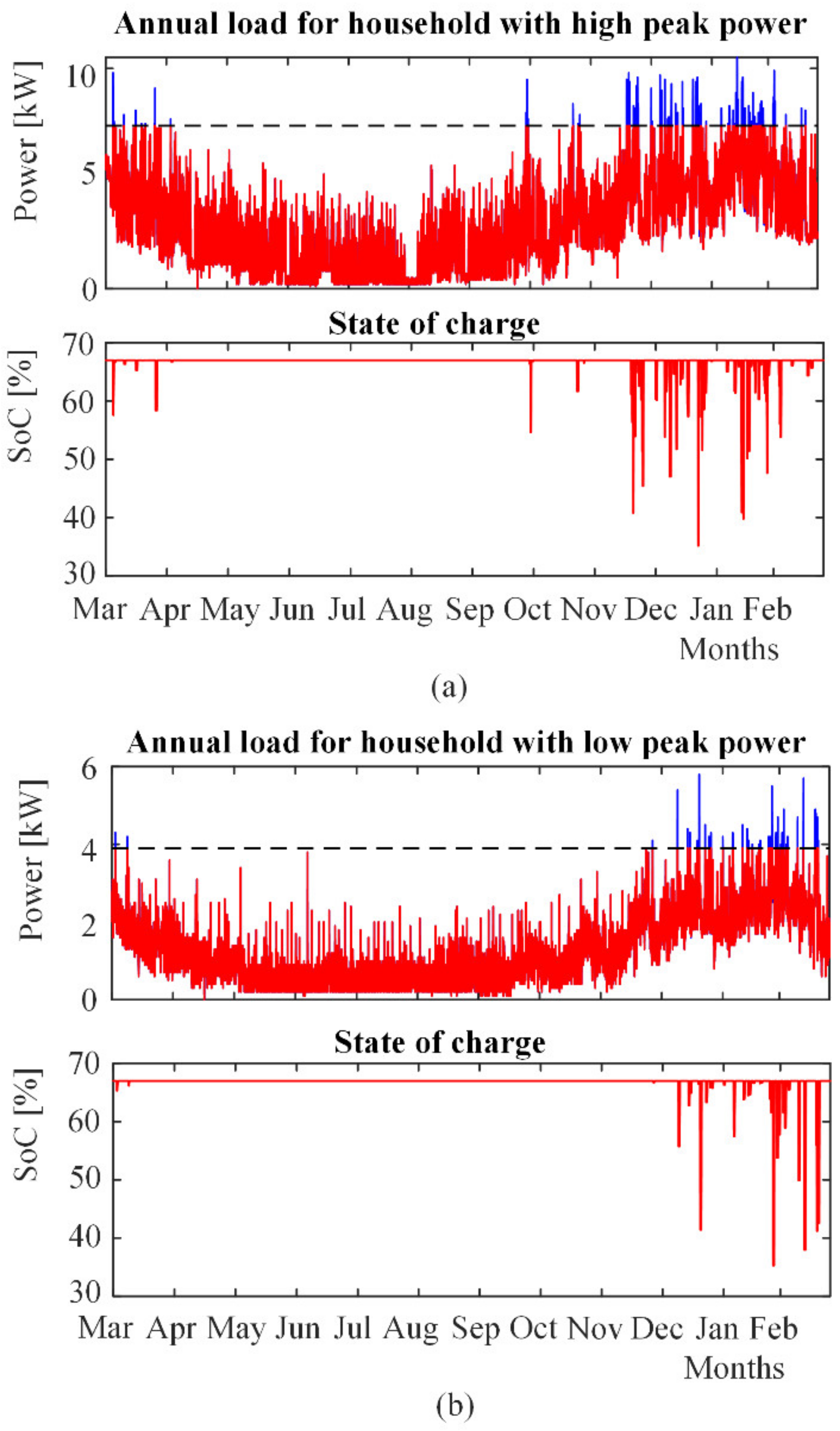
The power peak-shaving of the distributed BESS on the loading conditions for a double power peaks customer is shown in
Figure 18. Households with high power peak of 10.5 kW and a threshold limit of 7.4 kW present 29.5% reduction and battery capacity of 17.6 kWh. Households with low power peak of 5.8 kW and threshold limit of 3.9 kW present 33% reduction and battery capacity of 6.8 kWh.
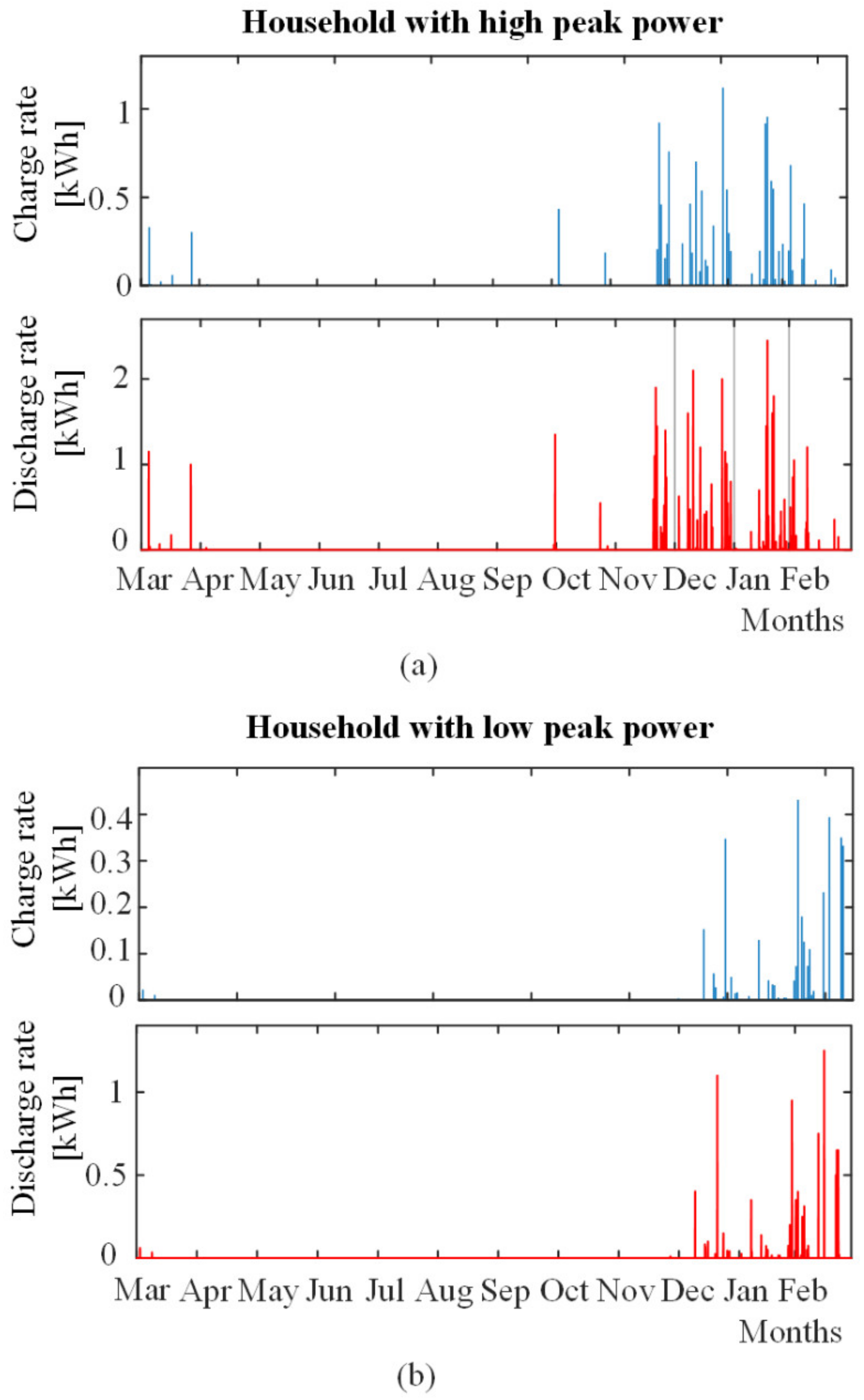
Figure 19 presents the charging and discharging rates in both cases. The maximum charging and discharging rate for high-power households is 1.21 kWh (0.069C C-rate) and 2.45 kWh (0.139C C-rate), respectively. The maximum charging and discharging rate for low-power households is 0.43 kWh (0.0632C C-rate) and 1.25 kWh (0.1834C C-rate), respectively.
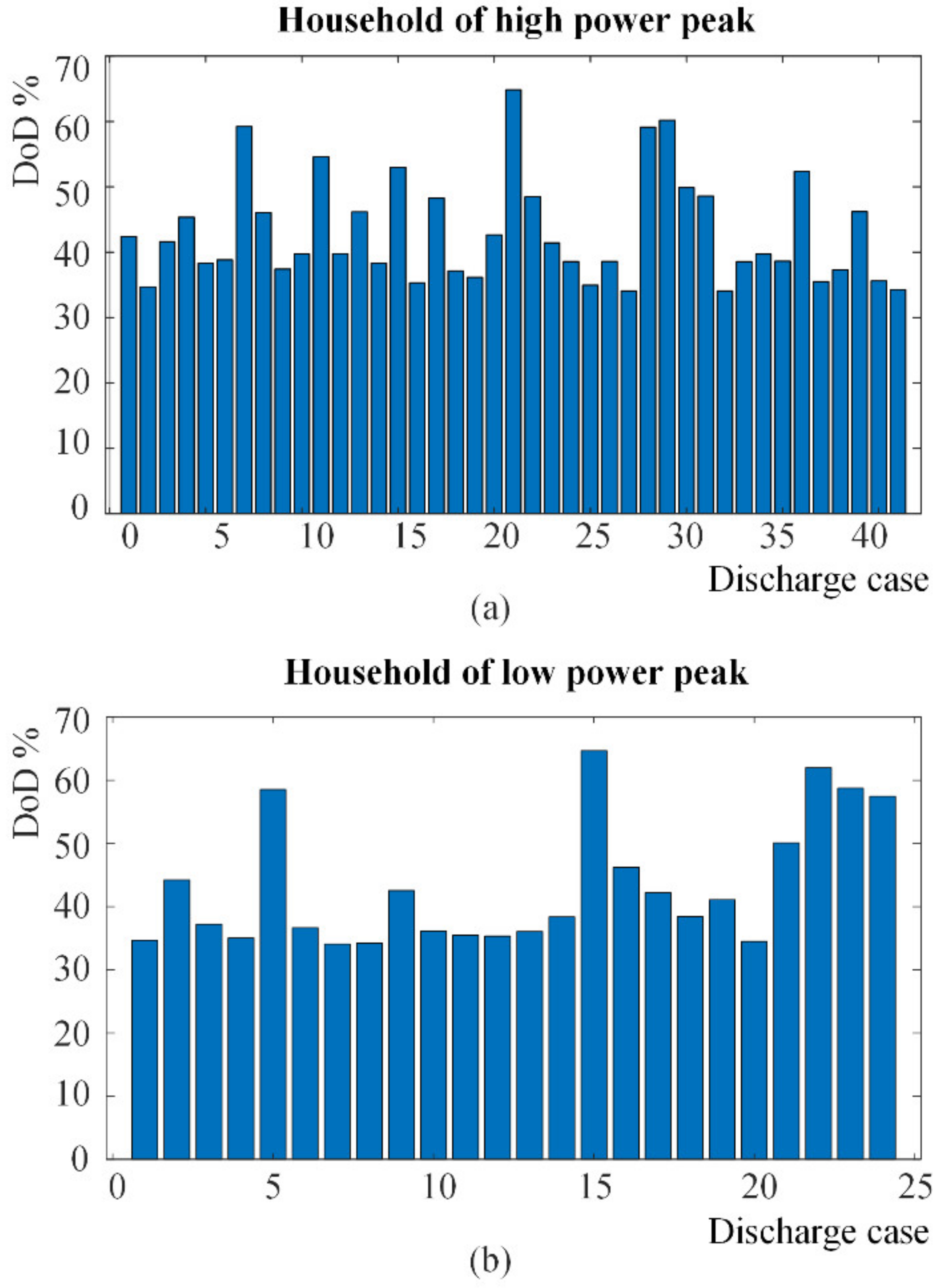
Figure 20 presents the DoD and the number of discharges in one year for both households with high power-peak and low power-peak. In
Figure 20a, one can see that for high power-peak households, the DoD varies between 34.10% and 64.71% in 41 days while, in
Figure 20b, one can observe that for low power-peak the DoD varies between 34.07% and 64.85% in 21 days.
3.2.2. Economic Calculations of Scenario 2
In this section, the total profit is calculated for the above presented distributed at the customers’ premises BESS for increasing threshold limits of 7.4 kW and 3.9 kW for high peak power and low peak power, respectively. The savings per year are calculated as in the case of the aggregated BESS.
In case of houses having high power peak,
Table 2 shows the highest power outages for each month for a year, depending on the reduced power peak. During November-March, a high-load charge is also charged, which requires information on the next highest power peak on weekdays between 06:00 and 18:00 for these months. Public holidays are not included in the calculations.
Table 3 shows the savings per year, payback time, and total savings for households with high power peak. Total profit with respect to profit period results in 10.56 year and payback time corresponding to 9.44 years. The profit time must be lowered in order for the total repayment to increase, which in this case is not possible since 3.1 kW is the maximum reduction for the household because of the threshold limit of 7.4 kW. Consequently, the threshold limit of 7.4 kW and 17.6 kWh offers the most profitable case.
For households with low power peak, the highest power output is as shown in
Table 4.
Table 5 shows the savings per year, payback time, and total savings. Total profit with respect to profit period results in 12.6 year and payback time corresponds to 7.4 years. The profit time must be lowered in order for the total repayment to increase, which in this case is not possible since 1.9 kW is the maximum reduction because of the threshold limit of 3.9 kW. Threshold limit of 3.9 kW and 6.8 kWh thus provides the most profitable case for this household.
If the threshold were to be generalized for the entire housing area and all households would reduce the power peak by 1.9 kW, the power peak at the transformer LV side would be lowered by 129.2 kW, which corresponds to a 45.7% reduction.
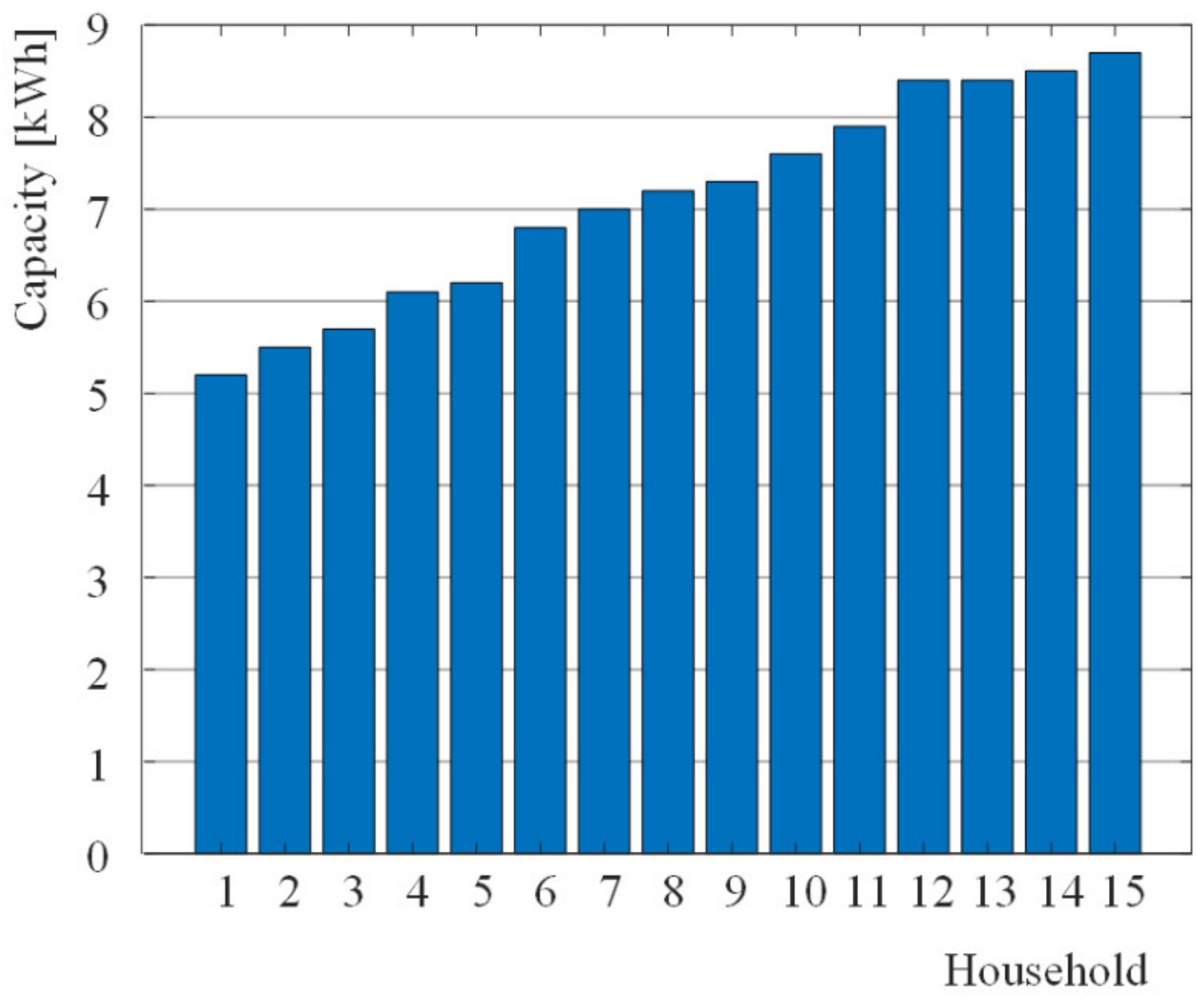
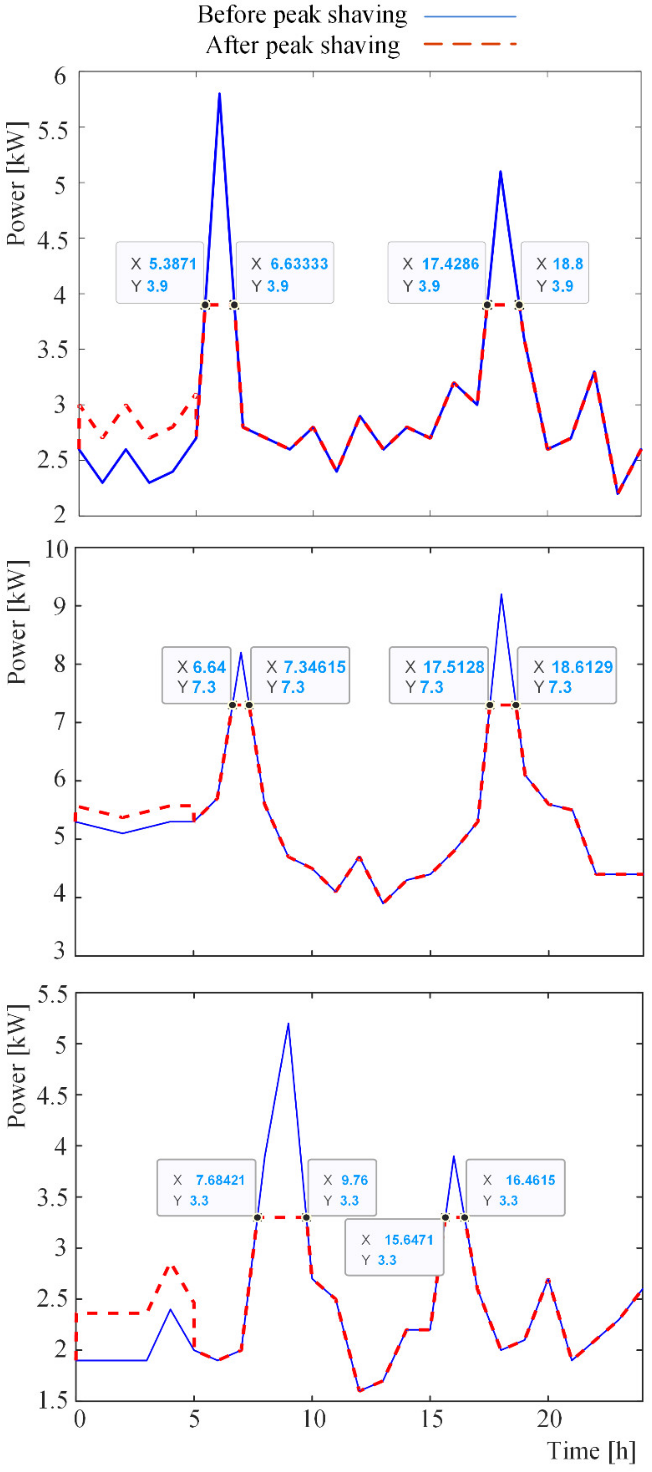
Figure 21 shows simulation results for 15 households with 1.9 kW reduction. The result shows that battery capacity varies between 5.2 and 8.7 kWh. The reason why equal reduction of power gives different battery capacity is due to the discharge time varying between these households as
Figure 22 indicates. The longer the discharge time, the higher the battery capacity needed.
4. Discussion
As regards the load profile at the transformer side, the power output is highest at 07:00 and 17:00 and the lowest between 22:00 and 05:00 on weekdays. On weekends, the power output is at its peak at 10:00 and 18:00 and the lowest between 00:00 and 07:00. The measured consumption patterns reveal high seasonal variation however, strong similarities during particular seasons revealed as well.
At the load side power profile, the measured residential consumption patterns revealed major differences leading to six consumption patterns. Hence, residential storage and power peak-shaving, especially in the case where the customer operates as prosumer, is case-by-case dependent. It is not wise to take for granted that energy storage should be conducted during night supposing that the energy demands are lighter. Thus, analysis of the individual consumption pattern, especially when the customer brings RES capabilities, is necessary in order to size an economically viable residential BES. It should be also highlighted that the customers who bring RES and BESS may participate in peer-to-peer (P2P) energy trading because their peak demands rise on different times during a 24-h period [
10,
13]. Optimal trading based on market tariffs is considered an important topic, which attracts high attention in the literature that, however, was not addressed in this investigation.
Both BESS were computed by using simulation models built in MATLAB. In the simulation models, the system loss is set to 15% and SoC may vary between 30 and 75% to protect battery health. The performance of each system depends on the preferred level for the reduction of the power peak, the initial investment that depends on the battery capacity size, the price and maintenance costs among other as well as on the charging fees that apply in each system. Preliminary simulations were used to avoid ranges of threshold limits that would lead to unrealistic sizes of batteries and payback periods. In the results section, representative results for different threshold limits were presented in each case while, the economic profitability was investigated on the basis of an initial investment that takes into account the battery cost and market prices and charges. Other factors were not taken into account because this work aims to explore the incentives from a qualitative manner for the integration of aggregated and distributed BESS rather than to respond on which systems is best. This is because the importance of each design on the power system value chain refers to different stakeholders, the DSO and the end-users in this case, as well as because the systems may have different objectives with respect to the overall power system operation.
Regarding the aggregated BESS, for a threshold limit and battery capacity that are set to 246 kW and 289 kWh respectively, which corresponds to a 13% reduction, the charge C-rate is 0.074 while the discharge C-rate is 0.1. Discharge takes place only 13 days a year between December-March with DoD varying between 22% and 70%. The battery can therefore be used for other applications such as a special AC or DC power lines for electrification of the wider transport sector and EVs integration [
5]. At present, the eligibility to install and utilize aggregated BESS either by separate energy storage companies or by individual customers is under investigation according to national and European laws. The customers might participate under a predefined contract having a predefined percentage of ownership of the storage investment.
Regarding the distributed BESS, households with high and low power peak were simulated. A threshold limit for households with high power peak that is 7.4 kW and battery capacity of 17.6 kWh gives a 29.5% reduction. Discharge takes place 41 days a year with DoD varying from 31.10–64.71%. Maximum charging and discharging rate is 1.21 kWh and 2.45 kWh respectively. A threshold limit for low peak power households that is 3.9 kW and battery capacity of 6.8 kWh results to 33.0% reduction. Discharge takes place 21 days a year with DoD varying from 34.07–64.85%. Maximum charging and discharging rate is 0.43 kWh and 1.25 kWh respectively.
Financial calculations for both BESS indicate that profitability depends on the threshold limit, battery capacity, payback time, profit time, and total profit. The calculations also show that the increased threshold limit does not provide the highest profitability due to a high battery capacity, which results in increased battery cost. The total profit in relation to the profit period appears a second-order dependency. For the aggregated BESS, the total profit is at most 41,474 SEK. For the distributed BESS with a high and low power peak, the total repayment will be maximum SEK 9430 and SEK 5544 respectively for 20 years (battery life). Investment of a battery system is recommended from 2030 onwards due to drastically falling battery expected prices in the coming years.
Threshold limit generalization was investigated by examining how much battery capacity is needed in a residential area to reduce the power peak by 1.9 kW. Fifteen households were analyzed. The results show that the battery capacity varies between 5.2 and 8.7 kWh due to varying discharge time. If all 68 households were to reduce their power peak by 1.9 kW, the transformer power peak would be reduced by 129.2 kW, which would give SEK 24,746 savings per year for the distribution company. The result indicates that there is a greater possibility of reducing the power peak by using distributed BESS.
5. Conclusions
Electrical power residential consumption patterns were studied in order to compute and examine an aggregated and a distributed BESS. Measurements at both the transformer and the load side were conducted and the analysis was performed at 15′ time intervals. Linear interpolation is used at time instants in between the measuring points. The examination of the aggregated and a distributed BESS reveal the advantages and disadvantages in each case. To mention a few in each approach, the advantage of placing the BESS at the transformer LV side is that any technical problems that arise in the system can be quickly resolved by the DSO. In addition, the objective of the aggregated BESS is to relieve the transformer loading conditions, to alleviate the risks in the distribution system because of markets implementation and to offer services for grid voltage and frequency stability. Moreover, there is no need for the DSO to convince the customers to install batteries behind their meters. On the other hand, the computations for the aggregated BESS reveal that an optimal case only from an economic perspective appear to offer less than 10% (actual value 6.2%) reduction of the power peak. This is due to the combination of the initial investment for the batteries, the prices, and the total lifecycle of the batteries. A higher reduction of the power peak as the one presented in
Section 3.1.1 that corresponds to 13% of the power peak (reduction value 36.8 kW) does not appear as the most profitable choice but offers higher relief to the transformer loading conditions. In the case of the distributed BESS, the computations revealed that when only the total profit is taken as objective, the reduction of the power peak might be more than 14% and 17% for residencies with high and low peak values respectively (reduction of power peak 1.5 kW and 1 kW respectively). Hence, by placing BESS behind the households’ meters, higher power system demand flexibility appears. However, the difficulty is that the national authorities and the DSO should work on the social acceptance of such systems by motivating customers to install a BESS in order to be favorable to all stakeholders i.e., the end-users, the DSO, the power producers, and the markets. Moreover, for the extended usage of distributed BESS, it is recommended to install higher resolution meters for detailed sampling of the highest power peaks. In particular, (near to-) real-time sampling, that is about 5 min, is suggested for proper management of the distribution grid. This is of great importance as long as the number of BESS, aggregated or distributed, increases since many stakeholders need to cooperate in an energy transaction market. As such, increased computations and data transfer are expected. Although there is literature which indicates that edge-computations and the associated telemetry are not heavy for a typical system of 500 end-users for a cloud-based management [
10], big-data handling and analytics are expected to increase accordingly and thus, special attention is required for successful digitalization of the distribution grid.
In practice, there is no special reason to distinguish which approach, aggregated BESS or distributed BESS, is best. This is because each approach is implemented in the power system by addressing similar objectives, as for example reduction of the power peak and profit maximization nevertheless, the aggregated BESS targets the total transformer loading conditions while the distributed BESS targets the end-user load profile. The transformer and the end-uses belong to different segments in the power system value chain that follow different security regulations and market laws. In particular, the directive framework for BESS at the end-users side is not clear and common around the globe, the DSO might follow the wholesale and/or retail market while for the end-users the market framework is not definite [
23]. In addition, the DSO is responsible for the power system security and stability while the end-users are responsible for their own properties. This makes obvious that there are different angles for the large-scale integration of BESS. In each perspective there are different objectives such as grid relief, cost profit, environmental impact, customer satisfaction, and comfort indexes that lead to complex optimization investigations.
To successfully integrate BESS in the distribution grid level, more future work needs to be conducted on power quality improvement, energy management, grid support, and system reserves because of their important role on system stability and operability. Especially in the presence of solar PV installations in which power harmonics are present [
24], although hosting capacity is expected to be improved [
25], special attention needs to be taken in order to keep low levels of total harmonic distortion [
26] because of transformer slow front transients [
27]. Furthermore, the utilization DC/DC and DC/AC converters in combination to the associated filters might lead to high frequency overvoltage [
28] for which the system parameters such as the loading conditions and the cabling have a critical role in the transformer insulation health [
29]. The operation of BESS in the distribution grid is correlated to demand response techniques from several stakeholders that shape the power system state according to several incentives by following advanced electricity markets strategies [
30] and management [
31]. However, the coordination of resources is a complicated task that affects the system performance and the economic benefits of all involved partners and thus, robust operational management is of highest priority [
32].
Author Contributions
Conceptualization, A.T. and S.H.; methodology, A.T. and S.H.; software, S.H.; validation, A.T. and S.H.; formal analysis, A.T. and S.H.; investigation, A.T. and S.H.; resources, S.H.; data curation, S.H.; writing—original draft preparation, A.T. and S.H.; writing—review and editing, A.T.; visualization, S.H.; supervision, A.T.; project administration, A.T. All authors have read and agreed to the published version of the manuscript.
Funding
This research received no external funding.
Institutional Review Board Statement
Not applicable.
Informed Consent Statement
Not applicable.
Data Availability Statement
Not applicable.
Acknowledgments
The authors would like to thank Karlstad El-och Stadsnät AB, Sweden, for providing the data.
Conflicts of Interest
The authors declare no conflict of interest.
Appendix A
The Coulomb method estimates SoC based on the of integration of the battery current time-dependent function when charging/discharging the battery [
33,
34]. By considering that the energy consumption is measured in kilowatt hours, SoC is calculated as
where C
kWh is the nominal battery capacity in kWh and P(t) is power as a function of time. DoD is calculated as
A simplified block-diagram of the calculations is shown in
Figure A1. The calculation starts by reading customers load profile and declaration of battery capacity and threshold limit. Thereafter Coulomb counting method with consideration to system losses 15% is implemented in order to calculate SoC which varies between 75% and 35%. Constant charging rate is executed between 00:00 and 05:00. If the power output is equal or exceeds the threshold limit during charging time, the charging time is postponed by one hour. Load profile after peak shaving can be generated by accumulating the original load profile with charging rate during charging time. The load profile is set to be equal to the threshold limit if the power output is greater than the peak value limit.
Figure A1.
The simplified block-diagram for the computations.
Figure A1.
The simplified block-diagram for the computations.
References
- Husin, H.; Zaki, M. Muhibbuddin A critical review of the integration of renewable energy sources with various technologies. Prot. Control Mod. Power Syst. 2021, 6, 3. [Google Scholar] [CrossRef]
- The European parliament and the council of the European Union, UE Directive (EU) 2018/2001 of the European Parliament and of the Council of 11 December 2018 on the Promotion of the Use of Energy from Renewable Sources. Available online: https://eur-lex.europa.eu/legal-content/EN/TXT/PDF/?uri=CELEX:32018L2001&from=fr (accessed on 7 December 2020).
- Sahaphol, H.; Elisabeth, W.; Stavros, L.; Andreas, T. Measurements and analysis of electri-cal power consumption patterns for the computation of an aggregated battery energy storage system. In Proceedings of the 2020 IEEE Interna-tional Conference on Environment and Electrical Engineering, Madrid, Spain, 9–12 June 2020. [Google Scholar]
- Maninnerby, H.; Bergerland, S.; Lazarou, S.; Theocharis, A. Electric Vehicle Penetration in Distribution Network: A Swedish Case Study. Appl. Syst. Innov. 2019, 2, 19. [Google Scholar] [CrossRef]
- Johansson, S.; Persson, J.; Lazarou, S.; Theocharis, A. Investigation of the Impact of Large-Scale Integration of Electric Vehicles for a Swedish Distribution Network. Energies 2019, 12, 4717. [Google Scholar] [CrossRef]
- Steve, S. Reducing energy demand: A review of issues, challenges and approaches. Renew. Sustain. Energy Rev. 2015, 47, 74–82. [Google Scholar]
- Georgilakis, P.S.; Hatziargyriou, N.D. A review of power distribution planning in the modern power systems era: Models, methods and future research. Electr. Power Syst. Res. 2015, 121, 89–100. [Google Scholar] [CrossRef]
- IRENA. Innovation Landscape Brief: Behind-the-Meter Batteries; International Renewable Energy Agency: Abu Dhabi, United Arab Emirates, 2019. [Google Scholar]
- Elmouatamid, A.; Ouladsine, R.; Bakhouya, M.; El Kamoun, N.; Khaidar, M.; Zine-Dine, K. Review of Control and Energy Management Approaches in Micro-Grid Systems. Energies 2020, 14, 168. [Google Scholar] [CrossRef]
- Nammouchi, A.; Aupke, P.; Kassler, A.; Theocharis, A.; Raffa, V.; Di Felice, M. Integration of AI, IoT and Edge-Computing for Smart Microgrid Energy Management. In Proceedings of the 2021 IEEE International Conference on Environment and Electrical Engineering and 2021 IEEE Industrial and Commercial Power Systems Europe (EEEIC/I&CPS Europe), Bari, Italy, 7–10 September 2021; pp. 1–6. [Google Scholar] [CrossRef]
- Luthander, R.; Widén, J.; Munkhammar, J.; Lingfors, D. Self-consumption enhancement and peak shaving of residential photovoltaics using storage and curtailment. Energy 2016, 112, 221–231. [Google Scholar] [CrossRef]
- Zheng, M.; Meinrenken, C.J.; Lackner, K.S. Smart households: Dispatch strategies and economic analysis of distributed energy storage for residential peak shaving. Appl. Energy 2015, 147, 246–257. [Google Scholar] [CrossRef]
- Hayes, B.; Melatti, I.; Mancini, T.; Prodanovic, M.; Tronci, E. Residential demand management using individualized de-mand aware price policies. IEEE Trans. Smart Grid 2017, 8, 1284–1294. [Google Scholar] [CrossRef]
- Leadbetter, J.; Swan, L. Battery storage system for residential electricity peak demand shaving. Energy Build. 2012, 55, 685–692. [Google Scholar] [CrossRef]
- Favuzza, S.; Ippolito, M.G.; Massaro, F.; Sanseverino, E.R.; Telaretti, E.; Zizzo, G. DEMAND Project: A Peak Load Shaving Strategy for End-User Consumers. In Proceedings of the 2018 IEEE International Conference on Environment and Electrical Engineering and 2018 IEEE Industrial and Commercial Power Systems Europe (EEEIC/ICPS Europe), Palermo, Italy, 12–15 June 2018. [Google Scholar]
- Sa’ed, J.; Favuzza, S.; Massaro, F.; Telaretti, E. Optimization of BESS Capacity Under a Peak Load Shaving Strategy. In Proceedings of the 2018 IEEE International Conference on Environment and Electrical Engineering, Palermo, Italy, 12–15 June 2018. [Google Scholar]
- Ke, B.-R.; Ku, T.-T.; Ke, Y.-L.; Chuang, C.-Y.; Chen, H.-Z. Sizing the Battery Energy Storage System on a University Campus with Prediction of Load and Photovoltaic Generation. IEEE Trans. Ind. Appl. 2015, 52, 1136–1147. [Google Scholar] [CrossRef]
- Lobato, E.; Sigrist, L.; Rouco, L. Use of energy storage systems for peak shaving in the Spanish Canary Islands. In Proceedings of the 2013 IEEE Power & Energy Society General Meeting, Vancouver, BC, Canada, 21–25 July 2013. [Google Scholar] [CrossRef]
- Karandeh, R.; Lawanson, T.; Cecchi, V. Impact of Operational Decisions and Size of Battery Energy Storage Systems on Demand Charge Reduction. In Proceedings of the 2019 IEEE Milan PowerTech, Milan, Italy, 23–27 June 2019. [Google Scholar] [CrossRef]
- Just, J.J.; Mwasilu, F.; Lee, J.; Jung, J.-W. AC-microgrids versus DC-microgrids with distributed en-ergy resources: A review. Renew. Sustain. Energy Rev. 2013, 24, 387–405. [Google Scholar] [CrossRef]
- Morstyn, T.; McCulloch, M.D. Multiclass Energy Management for Peer-to-Peer Energy Trading Driven by Prosumer Preferences. IEEE Trans. Power Syst. 2018, 34, 4005–4014. [Google Scholar] [CrossRef]
- Zia, M.F.; Benbouzid, M.; Elbouchikhi, E.; Muyeen, S.M.; Techato, K.; Guerrero, J.M. Microgrid Transactive Energy: Review, Architectures, Distributed Ledger Technologies, and Market Analysis. IEEE Access 2020, 8, 19410–19432. [Google Scholar] [CrossRef]
- Mousavi, M.; Wu, M. A DSO Framework for Market Participation of DER Aggregators in Unbalanced Distribution Networks. IEEE Trans. Power Syst. 2021, 14, 1–12. [Google Scholar] [CrossRef]
- Theocharis, A.D.; Pyrgioti, E.C.; Naxakis, A.I. Modelling of Photovoltaic Generators Based on a Linarized Equivalnet Circuit. In Proceedings of the International Conference on Renewable Energies and Power Quality (ICREPQ’12), Santiago de Com-postela, Spain, 28–30 March 2012. [Google Scholar]
- Mulenga, E. On the Hosting Capacity of Distribution Networks for Solar Power. Ph.D. Thesis, Luleå University of Tech-nology, Skellefteå, Sweden, 2021. [Google Scholar]
- Heine, P.; Hellman, H.; Pihkala, A.; Siilin, K. Battery Energy Storage for Distribution System—Case Helsinki. In Proceedings of the 2019 Electric Power Quality and Supply Reliability Conference (PQ) & 2019 Symposium on Electrical Engineering and Mechatronics (SEEM), Kärdla, Estonia, 12–15 June 2019; pp. 1–6. [Google Scholar]
- Theocharis, A.D.; Tzinevrakis, A.; Charalampakos, V.; Milias-Argitis, J.; Zacharias, T. Transformer modeling based on incremental reluctances. In Proceedings of the 2010 International Conference on Power System Technology, Hangzhou, China, 24–28 October 2010; pp. 1–7. [Google Scholar]
- Kuczek, T.; Florkowski, M.; Piasecki, W. Transformer Switching With Vacuum Circuit Breaker: Case Study of PV Invert-er LC Filters Impact on Transient Overvoltages. IEEE Trans. Power Deliv. 2016, 31, 44–49. [Google Scholar] [CrossRef]
- Theocharis, A.; Popov, M.; Terzija, V. Computation of internal voltage distribution in transformer wind-ings by utilizing a voltage distribution factor. Electr. Power Syst. Res. 2016, 138, 11–17. [Google Scholar] [CrossRef][Green Version]
- Xiao, D.; Chen, H.; Wei, C.; Bai, X. Statistical Measure for Risk-Seeking Stochastic Wind Power Offering Strategies in Electricity Markets. J. Mod. Power Syst. Clean. Energy 2021, 1, 1–6. [Google Scholar] [CrossRef]
- Tabandeh, A.; Hossain, M.J. Hybrid Scenario-IGDT-Based Congestion Management Considering Uncertain Demand Response Firms and Wind Farms. IEEE Syst. J. 2021, 1, 1–12. [Google Scholar] [CrossRef]
- Luo, Y.; Nie, Q.; Yang, D.; Zhou, B. Robust Optimal Operation of Active Distribution Network Based on Minimum Con-fidence Interval of Distributed Energy Beta Distribution. J. Mod. Power Syst. Clean Energy 2021, 9, 423–430. [Google Scholar] [CrossRef]
- Hannan, M.A.; Lipu, M.S.H.; Hussain, A.; Mohamed, A. A review of lithium-ion battery state of charge estimation and management system in electric vehicle applications: Challenges and recommendations. Renew. Sustain. Energy Rev. 2017, 78, 834–854. [Google Scholar] [CrossRef]
- Stefanopoulou, A.G.; Kim, Y. System-Level Management of Rechargeable Lithium-Ion Batteries. In Rechargeable Lithium Baterries; Woodhead Publishing Series in Energy; Woodhead Publishing: Sawston, UK, 2015; Chapter 10; pp. 281–302. [Google Scholar]
Figure 1.
The one-line diagram of the LV feeder under examination.
Figure 1.
The one-line diagram of the LV feeder under examination.
Figure 2.
Power consumption (a) from 1 March 2018 to 28 February 2019 and (b) during weekdays from June to August 2018.
Figure 2.
Power consumption (a) from 1 March 2018 to 28 February 2019 and (b) during weekdays from June to August 2018.
Figure 3.
Power consumption from 1 November 2018 to 31 March 2019 (a) during weekdays and (b) during weekends.
Figure 3.
Power consumption from 1 November 2018 to 31 March 2019 (a) during weekdays and (b) during weekends.
Figure 4.
The power peak and the total power consumption of the residential area under examination for each customer from 1 March 2018 to 28 February 2019.
Figure 4.
The power peak and the total power consumption of the residential area under examination for each customer from 1 March 2018 to 28 February 2019.
Figure 5.
The double-peaks consumption pattern.
Figure 5.
The double-peaks consumption pattern.
Figure 6.
The day-evening peak consumption pattern.
Figure 6.
The day-evening peak consumption pattern.
Figure 7.
The evening peak consumption pattern.
Figure 7.
The evening peak consumption pattern.
Figure 8.
The morning peak consumption pattern.
Figure 8.
The morning peak consumption pattern.
Figure 9.
The evening-night peak consumption pattern.
Figure 9.
The evening-night peak consumption pattern.
Figure 10.
The lamp posts consumption pattern.
Figure 10.
The lamp posts consumption pattern.
Figure 11.
Consumption patterns during weekends presenting (a) a peak in the morning, (b) a peak in the morning and a lighter peak in the evening, and (c) a peak in the morning and then slowly decreasing load demand.
Figure 11.
Consumption patterns during weekends presenting (a) a peak in the morning, (b) a peak in the morning and a lighter peak in the evening, and (c) a peak in the morning and then slowly decreasing load demand.
Figure 12.
(a) An aggregated BESS that responds to the aggregated load and (b) a distributed BESS where each battery responds to its own associated load.
Figure 12.
(a) An aggregated BESS that responds to the aggregated load and (b) a distributed BESS where each battery responds to its own associated load.
Figure 13.
Peak-shaving at the transformer LV side by using an aggregated BESS.
Figure 13.
Peak-shaving at the transformer LV side by using an aggregated BESS.
Figure 14.
(a) The charge and discharge rate and (b) the DoD in case of aggregated BESS.
Figure 14.
(a) The charge and discharge rate and (b) the DoD in case of aggregated BESS.
Figure 15.
The peak power charge, the variable grid charges, and the annual power output with respect to the reduced power peak.
Figure 15.
The peak power charge, the variable grid charges, and the annual power output with respect to the reduced power peak.
Figure 17.
The total profit versus the years of profit.
Figure 17.
The total profit versus the years of profit.
Figure 18.
Peak-shaving for a double power peaks by using distributed BESS in case of household for (a) high power peak and (b) low power peak.
Figure 18.
Peak-shaving for a double power peaks by using distributed BESS in case of household for (a) high power peak and (b) low power peak.
Figure 19.
Charging and discharging rates in case of (a) high power peak and (b) low power peak.
Figure 19.
Charging and discharging rates in case of (a) high power peak and (b) low power peak.
Figure 20.
Maximum DoD in each discharge cycle in case of (a) high power peak and (b) low power peak.
Figure 20.
Maximum DoD in each discharge cycle in case of (a) high power peak and (b) low power peak.
Figure 21.
Battery capacity needed to reduce the power peak by 1.9 kW.
Figure 21.
Battery capacity needed to reduce the power peak by 1.9 kW.
Figure 22.
Load profile before and after peak shaving in three different households and discharging times for different households.
Figure 22.
Load profile before and after peak shaving in three different households and discharging times for different households.
Table 1.
Economic calculations before and after reduction of the power peak.
Table 1.
Economic calculations before and after reduction of the power peak.
| Reduction [kW] | Battery Capacity [kWh] | Power Charge per Year [SEK] | Variable Charge per Year [SEK] | Savings per Year [SEK] | Payback for $100 per kWh [Years] | Payback for $50 per kWh [Years] | Total Profit for $50 per kWh [SEK] |
|---|
| 0 | - | 54,683 | 6660 | - | - | - | - |
| 17.8 | 57 | 51,410 | 6674 | 3439 | 15.89 | 7.94 | 41,474 |
| 27.8 | 166 | 49,470 | 6695 | 5358 | 29.71 | 14.87 | 27,487 |
| 36.8 | 289 | 47,724 | 6721 | 7077 | 39.55 | 19.56 | 3114 |
Table 2.
Maximum power output before and after reduction of the power peak for high power houses.
Table 2.
Maximum power output before and after reduction of the power peak for high power houses.
| Month | Before Reduction [kW] | Reduction 1.5 kW | Reduction 3.1 kW |
|---|
| March | Wednesday 8.10 Saturday 9.80 | Wednesday 8.10 Saturday 9.00 | Wednesday 7.40 Saturday 7.40 |
| April | 7.70 | 7.70 | 7.70 |
| May | 6.30 | 6.30 | 6.30 |
| June | 5.20 | 5.20 | 5.20 |
| July | 4.40 | 4.40 | 4.40 |
| August | 5.60 | 5.60 | 5.60 |
| September | 6.20 | 6.20 | 6.20 |
| October | 9.50 | 9.00 | 7.40 |
| November | Wednesday 9.80 Wednesday 9.60 | Wednesday 9.00 Wednesday 9.00 | Wednesday 7.40 Wednesday 7.40 |
| December | Tuesday 9.60 Saturday 9.70 | Tuesday 9.00 Saturday 9.00 | Tuesday 7.40 Saturday 7.40 |
| January | Thursday 10.50 Sunday 9.60 | Thursday 9.00 Sunday 9.00 | Thursday 7.40 Sunday 7.40 |
| February | Tuesday 9.90 Thursday 8.70 | Tuesday 9.00 Thursday 8.70 | Tuesday 7.40 Thursday 7.40 |
Table 3.
Economic calculations before and after reduction of the power peak for high power houses.
Table 3.
Economic calculations before and after reduction of the power peak for high power houses.
| Reduction [kW] | Maximum Power [kW] | Battery
Capacity [kWh] | High Charge per Year | Power Charge per Year [SEK] | Transmission Charge per Year [SEK] | Savings per Year [SEK] | Payback for $100 per kWh [Years] | Payback for $50 per kWh [Years] | Total Profit for $50 per kWh [SEK] |
|---|
| 0 | 10.50 | - | 2856 | 2361 | 1635 | - | - | - | - |
| 1.5 | 9.00 | 3.55 | 2630 | 2279 | 1661 | 282 | 12.07 | 6.03 | 4213 |
| 3.1 | 7.40 | 17.6 | 2206 | 2034 | 1719 | 893 | 18.90 | 9.44 | 9430 |
Table 4.
Maximum power output before and after reduction of the power peak for low power houses.
Table 4.
Maximum power output before and after reduction of the power peak for low power houses.
| Month | Before Reduction [kW] | Reduction 1.5 kW | Reduction 3.1 kW |
|---|
| March | Wednesday 4.30 Thursday 4.80 | Friday 4.30 Thursday 4.80 | Friday 3.90 Thursday 3.90 |
| April | 3.10 | 3.10 | 3.10 |
| May | 3.40 | 3.40 | 3.40 |
| June | 3.80 | 3.80 | 3.80 |
| July | 2.40 | 2.40 | 2.40 |
| August | 2.40 | 2.40 | 2.40 |
| September | 2.50 | 2.50 | 2.50 |
| October | 3.10 | 3.10 | 3.10 |
| November | Friday 4.20 Tuesday 3.90 | Friday 4.20 Tuesday 3.90 | Friday 3.90 Tuesday 3.90 |
| December | Monday 5.80 Thursday 5.40 | Monday 4.80 Thursday 4.80 | Monday 3.90 Thursday 3.90 |
| January | Wednesday 5.50 Tuesday 4.50 | Wednesday 4.80 Tuesday 4.50 | Wednesday 3.90 Tuesday 3.90 |
| February | Friday 5.70 Tuesday 4.90 | Friday 4.80 Tuesday 4.80 | Friday 3.90 Tuesday 3.90 |
Table 5.
Economic calculations before and after reduction of the power peak for low power houses.
Table 5.
Economic calculations before and after reduction of the power peak for low power houses.
| Reduction [kW] | Maximum Power [kW] | Battery
Capacity [kWh] | High Charge per Year | Power Charge per Year [SEK] | Transmission Charge per Year [SEK] | Savings per Year [SEK] | Payback for $100 per kWh [Years] | Payback for $50 per kWh [Years] | Total Profit for $50 per kWh [SEK] |
|---|
| 0 | 5.80 | - | 1521 | 1131 | 753 | - | - | - | - |
| 1.0 | 4.80 | 1.65 | 1366 | 1113 | 757 | 169 | 9.36 | 4.68 | 2467 |
| 1.9 | 3.90 | 6.80 | 1163 | 1028 | 774 | 440 | 14.82 | 7.40 | 5544 |
| Publisher’s Note: MDPI stays neutral with regard to jurisdictional claims in published maps and institutional affiliations. |
© 2022 by the authors. Licensee MDPI, Basel, Switzerland. This article is an open access article distributed under the terms and conditions of the Creative Commons Attribution (CC BY) license (https://creativecommons.org/licenses/by/4.0/).
