Article

A Position Sensorless Closed-Loop Control Mode of a Three-Phase Hybrid Stepper Motor

Department of Control Science and Engineering, University of Shanghai for Science and Technology, Shanghai 20093, China
*
Author to whom correspondence should be addressed.
Energies 2022, 15(3), 804; https://doi.org/10.3390/en15030804
Submission received: 23 December 2021 / Revised: 14 January 2022 / Accepted: 20 January 2022 / Published: 22 January 2022
(This article belongs to the Special Issue Advanced Electrical Machine Design and Optimization)

Abstract

:
The demand for the high-performance and low-cost position control actuators in many applications promotes the development of three-phase hybrid stepper motors. The torque ripple, loss, and pullout torque of the motor are the key factors to be considered in the motor application. In order to solve the problems of the open-loop control mode, this paper proposes a new “sensorless closed-loop” control mode to significantly improve the performance of three-phase hybrid stepper motors. This control mode is developed by estimating the rotor position with the Extended Kalman filter observer, thereby realizing the closed-loop control of the motor with sensorless technology. This paper illustrates the effects of this control mode by analyzing motor noise, losses, and pullout-torque. The results show that the use of the “sensorless closed-loop” control mode presented can effectively improve the performance of the stepper motor while maintaining the advantages of the motor in terms of cost and size. These results have positive significance for the development, application, and promotion of high-performance three-phase hybrid stepper motor systems.

1. Introduction

Hybrid stepper motors (HSMs) are used in a wide range of applications due to their advantages in performance and cost. Compared to the two-phase hybrid stepper motor (2P-HSM), the three-phase hybrid stepper motor (3P-HSM) is expanding its market share and will play an increasingly important role in the market due to its high resolution, low noise, and simple control [1].
HSMs are often used as actuators for position control, and its common control mode is open-loop control without additional physical sensors [1,2]. The performance of 3P-HSM is related to its electromagnetic (EM) structure, motor material, and manufacturing process. However, the performance of the motor is also closely related to its controller. How to use the control method to make the motor show better performance is the focus of many applications. Under the open-loop control mode, in order to prevent the occurrence of a lost step, the controller must drive the motor with a large current to increase the amplitude of its “Torque-Angle Characteristic” (TAC). The strong vibration and noise are thus induced, and the copper loss is thus certainly increased in motor operation. Moreover, with the increase of motor speed, the “Pullout-Torque” of the motor will drop, and the motor speed is thus limited. To solve these problems, some researchers have proposed the subdivision control modes to subdivide the drive current; the motor performance can thus be improved in terms of stability, vibration, and noise [2]. However, the subdivision control mode cannot effectively solve the problem of large drive current.
The Field Oriented Control (FOC) mode is a highly regarded control technique for permanent magnet synchronous motor (PMSM) applications today [3,4]. This control mode can effectively reduce the drive current and running noise of the motor. However, the suitability of this control mode for many other motors, including stepper motors, is subject to further research work [5,6]. The results of this paper show that the characteristics of a 3P-HSM are adapted to the FOC mode. In order to realize the sensorless closed-loop control (SCLC) of stepper motors, this paper present the results from using sensorless FOC mode for 3P-HSM and “Extended Kalman filter” (EKF) position observer for replacing the physical position transducer.
In the steady-state operation, the noise source of HSMs can be divided into three aspects: mechanical noise, aerodynamic noise, and the noise induced by EM sources [7,8]. The mechanical noise and aerodynamic noise are caused by the moving parts and working environment of the motor and will not be discussed in detail in this paper. The EM noise is caused by EM factors such as unbalanced magnetic pull (UMP), torque ripple, the magnetostrictive effect, and the forces in current-carrying conductors. EM noise is closely related to the control mode of HSMs [9,10,11]. This paper focuses on the issues generated by the control mode.
The vibration and noise are inseparable in the motor operation. The noise caused by torque ripple certainly contains the information of the ripple in its spectrum [12]. Therefore, the influence of control mode on the EM torque can be revealed by detecting the motor noise. For 3P-HSM, due to the large number of magnetic pole-pairs, it is difficult to measure directly the torque ripple with a contact measuring device such as the torque transducer. However, the non-contact noise test method for measuring motor noise can provide a clear picture of motor torque pulsation [12,13].
The loss of a motor mainly includes the copper loss of armature winding, the iron loss, and the mechanical loss of bearings and air ducts [14]. The loss discussed here is mainly the copper loss as it is closely linked with the control mode.
The pullout torque of a stepper motor is associated with many factors, including the drive mode. Traditionally, subdivision open-loop control mode is used to increase the pullout torque by increasing the drive current. Such control mode inevitably leads to an increase in the copper consumption of the motor. The technology to increase the pullout torque with a small drive current is of great interest in the application of stepper motors.
This paper presents a control mode that can significantly improve the performance of 3P-HSM: the “position sensorless closed-loop” control mode. This control mode significantly reduces the copper consumption of the motor, increases the pullout torque of the motor, and reduces the noise of the motor. Test results also confirm the effectiveness of this control method.

2. Analysis of the Characteristics of 3P-HSM

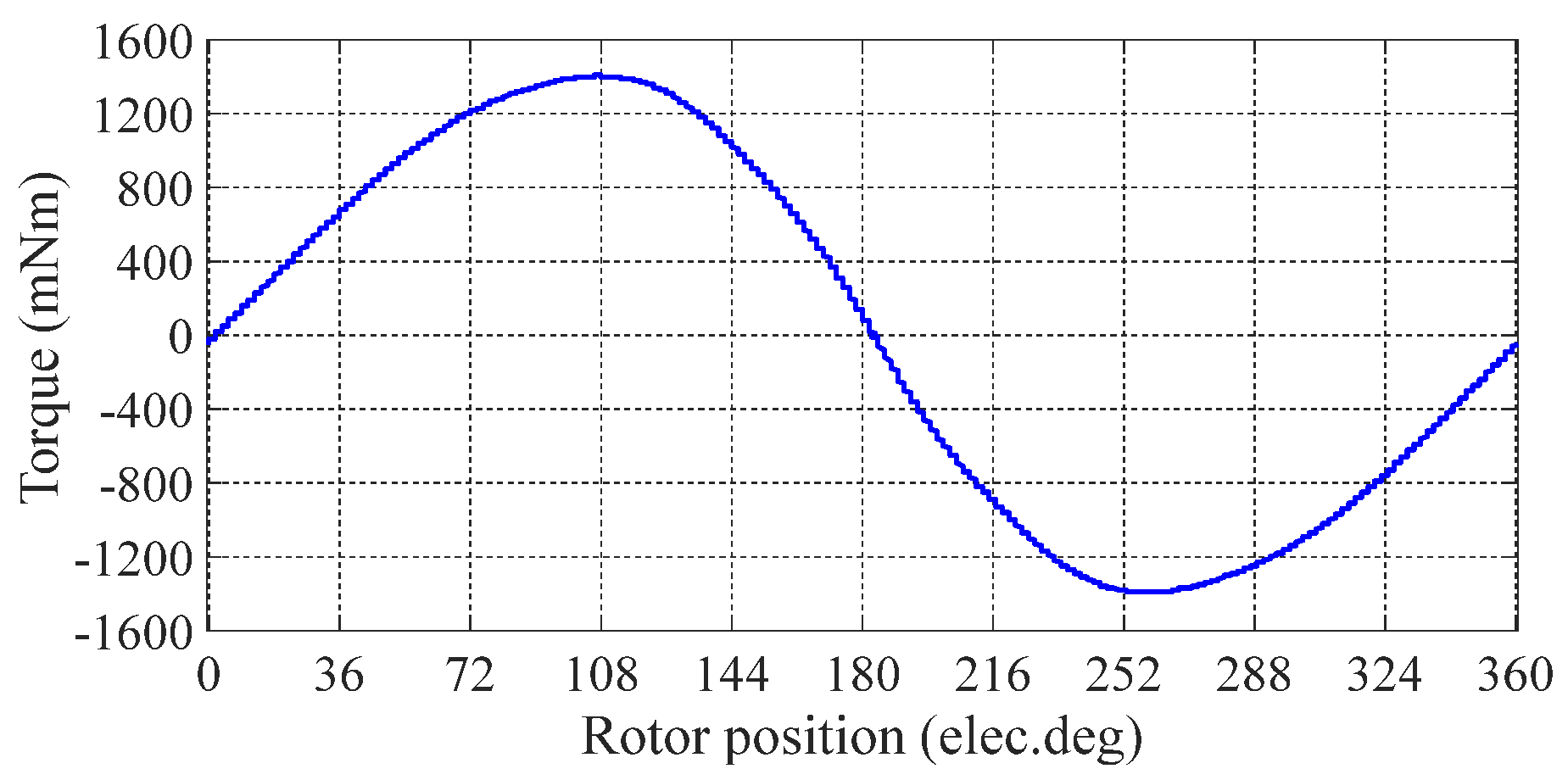
2.1. Torque Angle Characteristic of 3P-HSM

Ignoring the influence of high-order torque harmonics, the EM torque of HSM generated by single-phase current can be expressed as
T p = p Ψ f I s sin β
where, p is the number of poles of the motor (i.e., the number of rotor teeth of the motor), Ψf is the rotor flux, Is is the input current, β is the angle between the stator and rotor magnetic fields. When the current is constant, the torque represented by Equation (1) is also known as the “TAC” of stepper motors [15].
In fact, for a commercial stepper motor, its TAC contains not only the fundamental component as shown in Equation (1), but also high-order harmonic components.
When all 3-phase windings are energized, in a linear state, the combined torque of the motor can be calculated by superposing the EM torque generated by each phase current,
T a b c = T e a + T e b + T e c = 3 2 p Ψ f I m cos α
where, Im is the amplitude of drive current, α is the phase difference between the current and the back-emf.
Since the magnetic field generated by the stator winding is directly related to the drive current, and the back-emf of the motor winding has a 90° difference with the rotor flux linkages, Equation (2) can be changed to:
T a b c = 3 2 p Ψ f I m sin δ
where, δ is the angle between the stator flux linkage and the rotor flux linkage.
Equations (2) and (3) show that, when the stator flux linkage is orthogonal to the rotor flux linkage, i.e., the phase difference α between the current and the back-emf is zero, the EM torque can be maximum under the same drive current. In this case, the stator flux linkage is orthogonal to the rotor flux linkage and the copper loss of the motor can be minimized.
For the 3P-HSM tested in the authors’ research, its TAC is shown in Figure 1, which contains a few high-order harmonic components.
The TAC of the stepper motor moment angle characteristic also reflects the relationship between the EM torque and the angle β between the stator and rotor magnetic fields of the motor. From the stability analysis, when β is in the region of dTP/dβ > 0, the rotor is in the stable region [16,17]. For the ideal stepper motor, its TAC is shown in Equation (1), i.e., the stable region of the stepper motor is in (0°, 90°) in the motor operation state. When β is outside of the region, the operation of the motor is unstable, and it will lose a step or even stall. Therefore, when the FOC mode is used in motor control, the controller can adjust the EM torque timely according to the rotor position, so that the rotor can be kept in the stable region and generate the required EM torque with a smaller current.

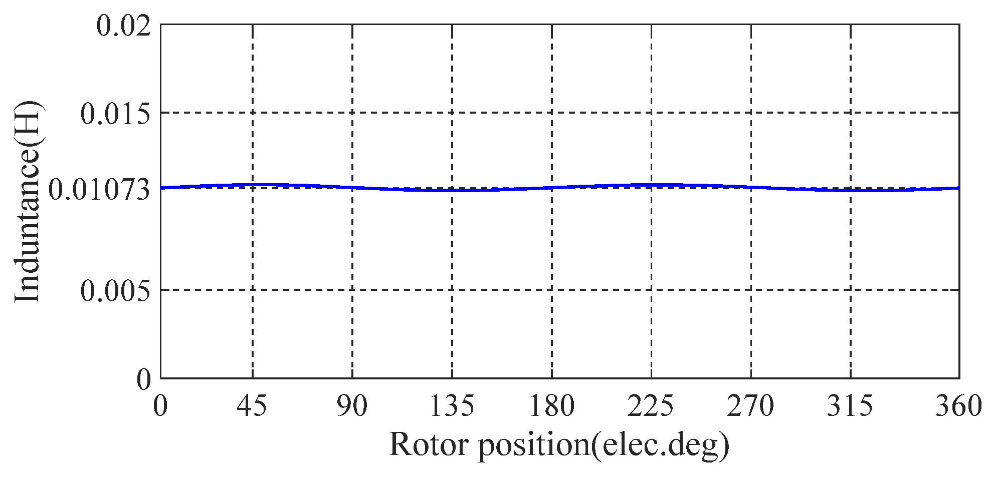
2.2. Characteristics of Motor Armature Inductance

In terms of EM characteristics, a 3P-HSM has similar characteristics to PMSM. EM analysis showed that, for the hybrid stepper motor used in the test, the main magnetic field component responsible for the saturation effect is the magnetic field generated by the permanent magnet mode of NdFeB on the rotor. The 3P-HSM used in the authors’ research is a commercial product with a typical EM structure of 3P-HSM. Figure 2 shows the curve of the motor’s armature inductance as a function of rotor angle. Figure 3 shows the back-emf curve of the armature winding in the time domain during steady state operation of the motor.
It can be seen from Figure 2 that the motor inductance varies by less than 0.8% of its average value over an electrical cycle, so the inductance of such motors can be treated as a constant value during motor operation. It can also be seen in Figure 3 that the motor has good sinusoidality of the back-emf curve. These EM characteristics show that this hybrid stepper motor can be analyzed and controlled as a PMSM with a surface mounted magnet rotor, and that many of the control modes which were effective for PMSM should also be available for use in hybrid stepper motors, including the FOC mode [18].
Due to the inductance of the armature, winding hardly changes with the position of the rotor and the reluctance torque of 3P-HSM can be ignored in motor control. For this kind of synchronous motor with sinusoidal back-emf, the FOC mode is undoubtedly very effective. The use of the FOC mode and the estimation of the motor rotor position by means of an observer for closed-loop control [19,20], and the use of the direct axis current Id to zero, allows to realize the SCLC of the motor.

2.3. FOC of a Permanent Magnet Synchronous Motor

The principle of the FOC mode is to drive a synchronous motor with a sinusoidally symmetrical current and, during the drive, to adjust the angular difference between the flux-linkages of stator rotor so that the performance of the motor is optimal [21]. The FOC mode enables “closed-loop control” of the motor position as the angle of the rotor is detected and controlled in the operation of the motor [22]. As the closed-loop control of the rotor position is realized by the “angle observer” algorithm instead of the “physical position sensor” [23], this control mode is defined here as the SCLC mode. The overall control block diagram for the constant speed control is shown in Figure 4.
From Equation (3), when the reluctance torque of the motor is negligible, the torque generated by the unit current can be maximum when the stator flux-linkage is orthogonal to the rotor flux-linkage. In this case, for the same load, the drive current can be minimum [24,25]. The reduction of current will certainly lead to the reduction of acoustic noise and cupper loss during the motor operation.
The existing FOC mode often uses additional physical sensors, such as optical encoders or Hall sensors, to observe and control the angle between the magnetic fields of the motor stator and rotor [26]. However, the use of the sensors makes the stepper motor lose its superiority in terms of cost and size. In addition, the sensor is easily affected by its environment, which also limits the application of the motor [27]. Since most position sensors use a local effect, such as local light or local magnetic field, in detecting the rotor position, the motor performance should be affected by the error of the local effect. The use of a “sensorless” mode can avoid the use of physical sensors, and the problems induced by the sensor can thus be avoided. As the EM torque is a global effect of the motor, and the overall EM effect of the motor is used in the sensorless FOC to estimate the angle between the stator and rotor fields, the angle obtained by the observer of the mode is more meaningful in the generation of EM torque. In this way, the relative angle between the stator and rotor flux-linkages can be adjusted effectively and timely, so that the maximum EM torque of the motor per unit current can be realized [28].
Figure 5 shows the three-phase current waveform under the FOC mode in the authors’ test. It shows that the three-phase currents are sinusoidal, and this is desired for the motor with the TAC described by Equation (1). Therefore, using the FOC mode should be more effective in reducing the vibration and noise of the 3P-HSM.

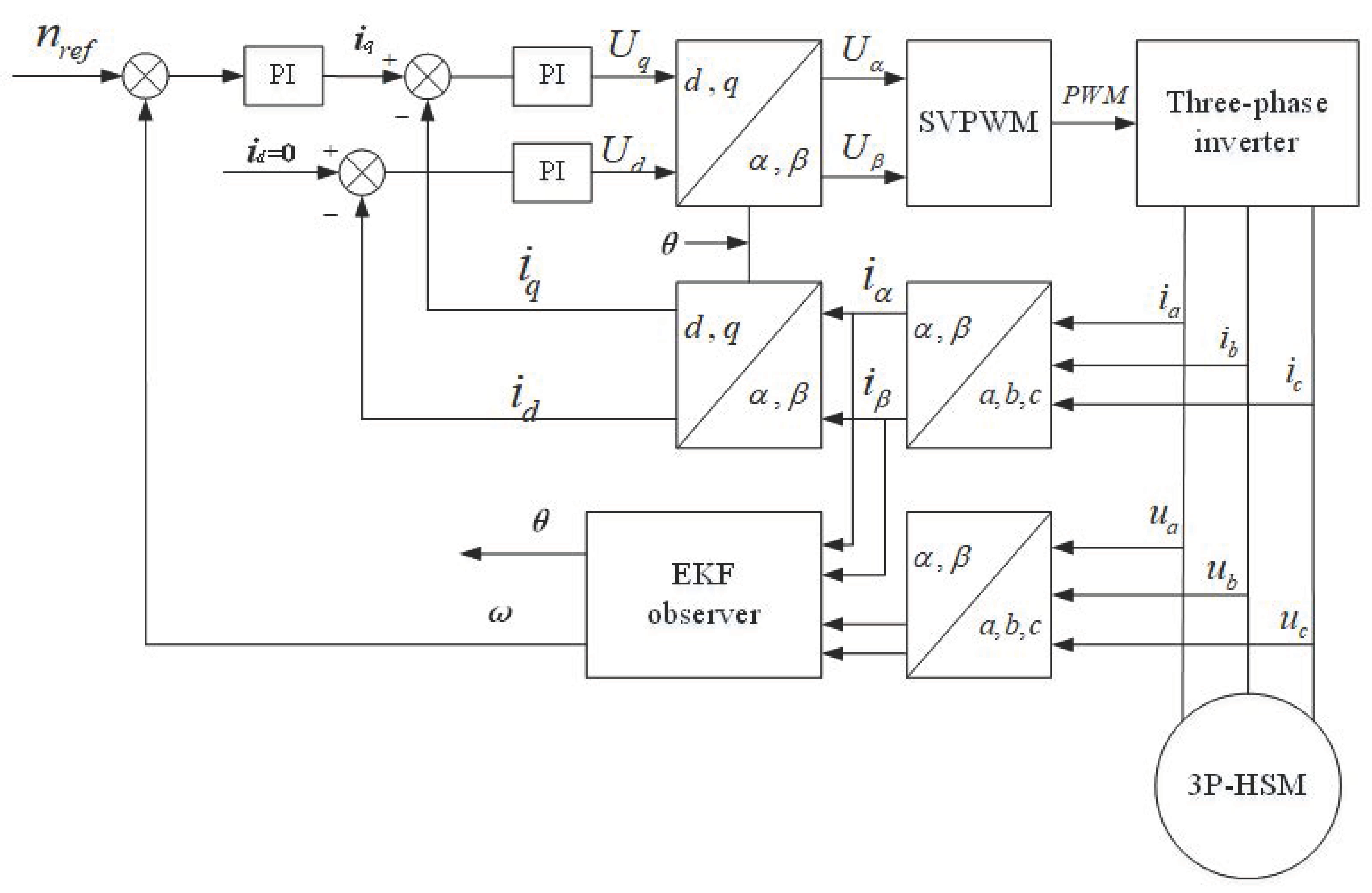
3. Mathematical Model and Observer Design of 3P-HSM

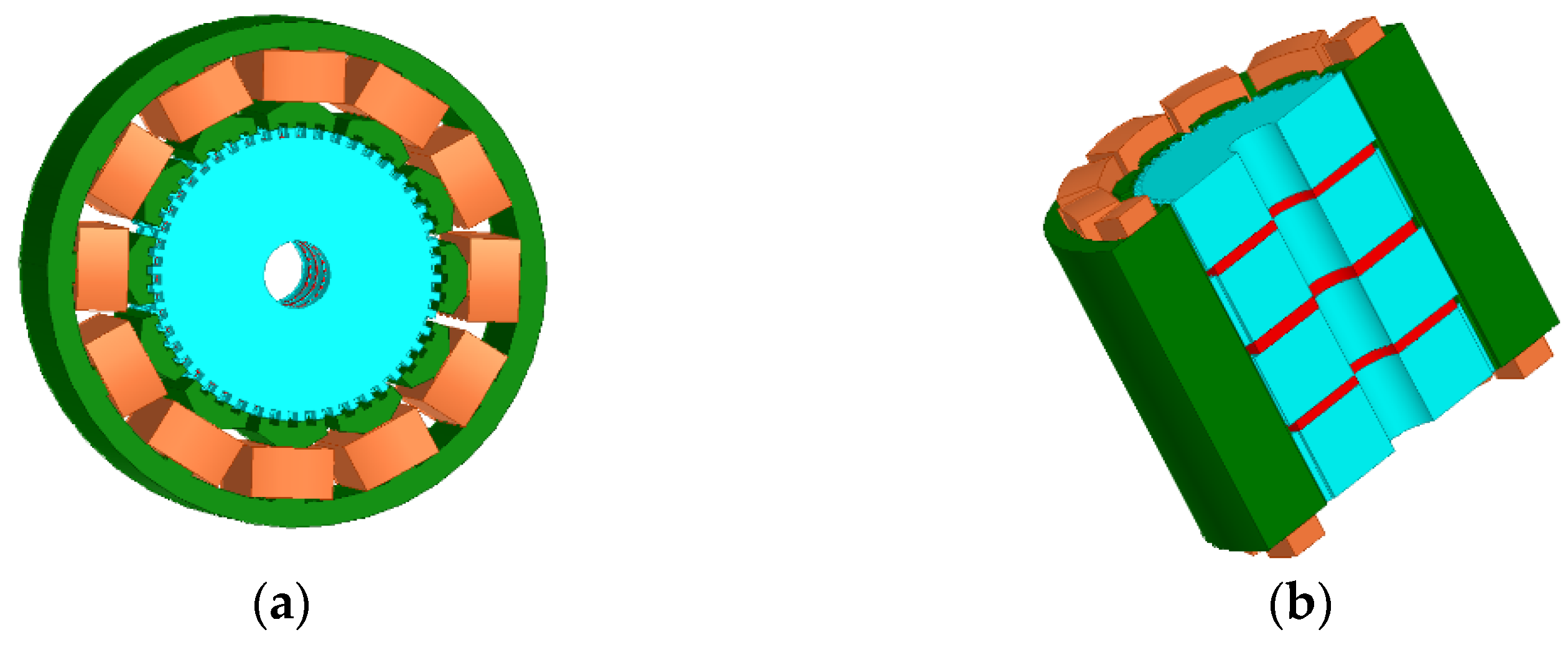
3.1. Mathematical Model of 3P-HSM

The motor stator voltage equation of 3P-HSM in the α-β coordinate system is [15]
u α u β = R S 0 0 R S i α i β + d d t L S 0 0 L S i α i β + e α e β
where, uα and uβ are the stator voltages, iα and iβ are the stator currents, in the α-β coordinate system; RS is the stator phase resistance; LS is the stator phase inductance; eα and eβ are the back-emf of the armature winding of the motor. It is well known that the back-emf can be further expressed as,
e α e β = cos θ sin θ E = 4.44 N s k N s ϕ m cos θ sin θ f 1
where, E is the motor back-emf constant, NS is the number of turns of the stator winding in series, kNS is the stator fundamental winding coefficient, ϕm is the air gap magnetic flux per pole, f1 is the stator current frequency, θ is the position angle of the rotor.
The values id and iq of the drive current in the d-q coordinate system can be obtained from the values iα and iβ of the current in the α-β coordinate system,
i d i q = cos θ sin θ sin θ cos θ i α i β
The EM torque Tem balance equation is:
T e m = J d ω d t + B m ω + T L
where, ω is the mechanical speed of the motor; J is the moment of inertia; Bm is the friction coefficient of the motor; TL is the load torque.
By controlling the straight axis current with id = 0, the stator current is all torque current, so that the motor can produce the required torque with the minimum current, which also minimizes the cupper losses in the operation of a stepper motor.

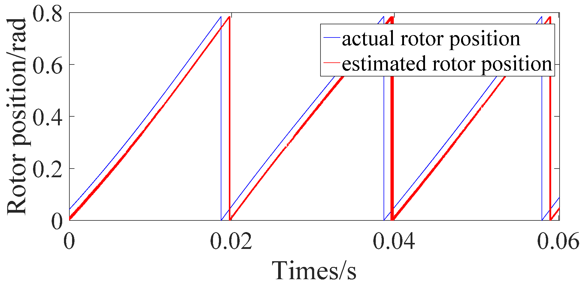
3.2. EKF Position Observer

Rotor position estimation is an important part of determining the sensorless FOC mode and its effect determines the quality of SCLC. After analyzing and researching a variety of observers, the authors decided to use the “EKF Observer” to realize the SCLC of 3P-HSM.
The 3P-HSM model in the α-β coordinate system was rewritten as [29]:
u α = R S i α + d Ψ α / d t u β = R S i β + d Ψ β / d t
Ψ α = L S i α + Ψ r cos θ Ψ β = L S i β + Ψ r sin θ
where, Ψα and Ψβ are the flux-linkages of the motor excitation winding in the α-β coordinate system, Ψr is the flux-linkage generated by the permanent magnet on the motor. Substituting Equation (9) into Equation (8):
u α = R S i α + L S d i α / d t Ψ r p ω sin ( p ω t ) u β = R S i β + L S d i β / d t + Ψ r p ω cos ( p ω t )
In the actual system, the mechanical constant of 3P-HSM is much larger than the electrical constant, and ω can thus be considered as constant in a sampling period, i.e., Δω = 0. Then, the corresponding nonlinear equation of the system is [29]:
d d t x = f ( x ) + B u y = C x
Here:
x = [ i α i β ω θ ] T u = [ u α u β ] T y = [ i α i β ] T
f ( x ) = R S L S i α + ω Ψ r L S sin θ R S L S i β ω Ψ r L S cos θ 0 θ
B = [ 1 L S 0 0 0 0 1 L S 0 0 ] C = [ 1 0 0 1 0 0 0 0 ]
and the discrete model obtained by using the EKF algorithm is:
x ( k + 1 ) = f [ x ( k ) ] + B ( k ) u ( k ) + V ( k ) y ( k ) = C ( k ) x ( k ) + W ( k )
where, V(k) is the system noise, w(k) is the measurement noise.
Assuming that V(k) and W(k) are both zero-mean white noise [29]:
E { V ( k ) } = 0 E { W ( k ) } = 0
where, E {} is the expected numerical value.
In the recursive calculation of the EKF algorithm, instead of using the noise vectors V and W directly, the covariance matrix Q of V and the covariance matrix R of W are used. The basic consideration in choosing the parameters Q and R is to ensure convergence of the filtering algorithm and to enable the algorithm to quickly track the actual state of the system. In the actual selection of the parameters, experiments should be carried out in advance for the specific motor to select the best overall performance. The values chosen in this paper are as follows:
Q = 0.1 0 0 0 0 0.1 0 0 0 0 25 0 0 0 0 0.4
R = 0.2 0 0 0.2
According to the internal state variables and input feedback of the motor, the 3P-HSM state equation can be established,
d i α d t = R S i α L S + Ψ r L S p ω sin ( p ω t ) + u α L S d i β d t = R S i β L S Ψ r L S p ω cos ( p ω t ) + u β L S d θ d t = p ω
compared with electrical variables, the change of mechanical ones is much slower. In order to construct the rotor position observer, Formula (19) can be transformed into:
d i α d t = R S i α L S + e α L S + u α L S + K 1 ( i α i α ) d i β d t = R S i β L S e β L S + u β L S + K 1 ( i β i β ) d e α d t = p ω e β + K 2 ( i α i α ) d e β d t = p ω e α + K 2 ( i β i β )
where, i ^ α and i ^ β are the estimated currents, K1 and K2 are the coefficients of the EKF observer, e ^ α and e ^ β are the estimated back-emf. Based on these results, the motor rotor position angle can thus be obtained:
θ = p ω t = arctan ( e ^ β / e ^ α )
In an actual control system, the rotor position of the stepper motor can be estimated by Equation (21). Figure 6 shows the simulation results of the actual rotor position and estimated rotor position during the steady-state operation of the motor. It can be seen that the estimation error of motor rotor position is quite small in the stable operation of the motor. Therefore, by adjusting the appropriate controller parameters, the sensorless control technology based on the EKF observer can be applied to the actual closed-loop control of 3P-HSM.

4. Effect of SCLC Mode on Performance of 3P-HSM
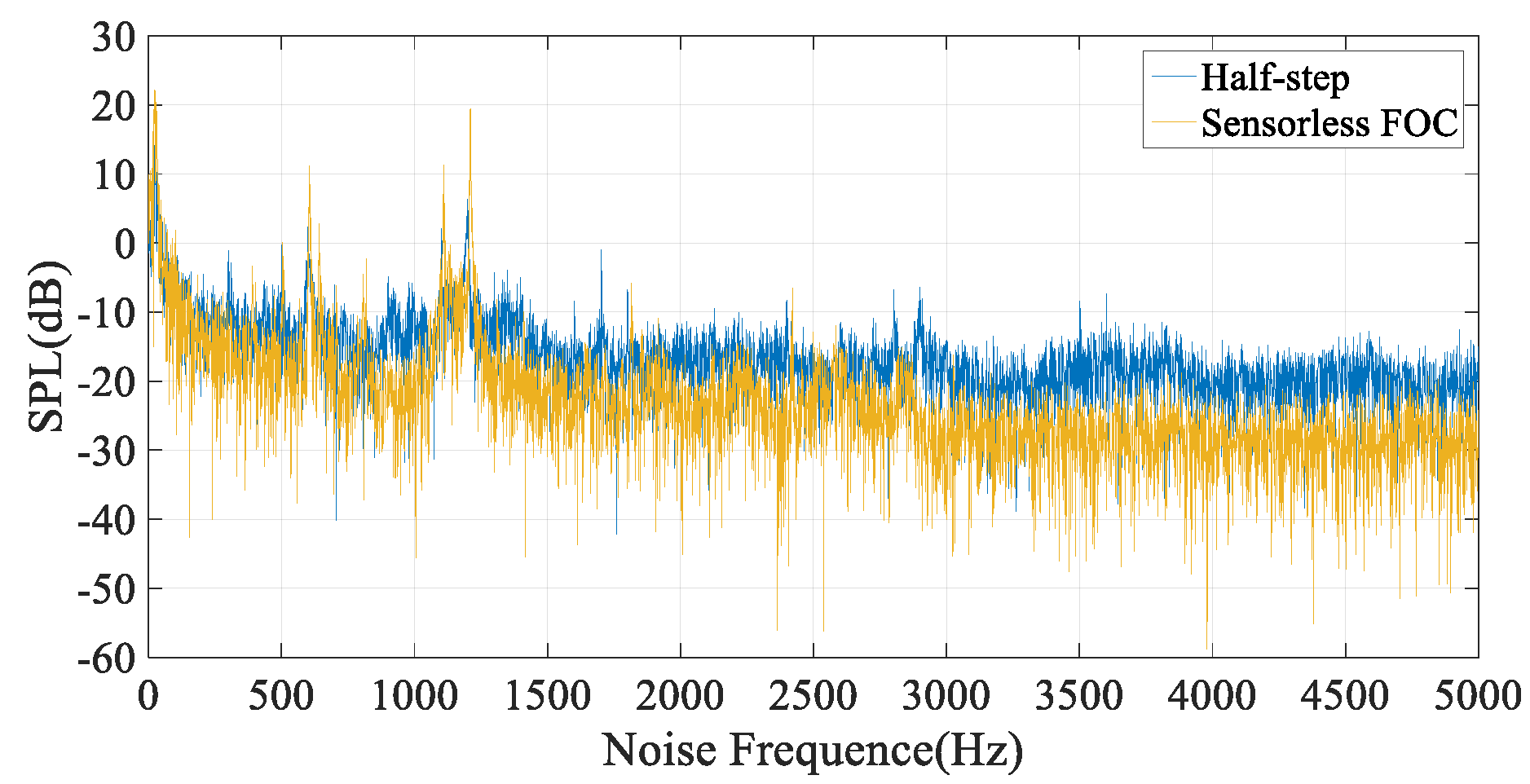
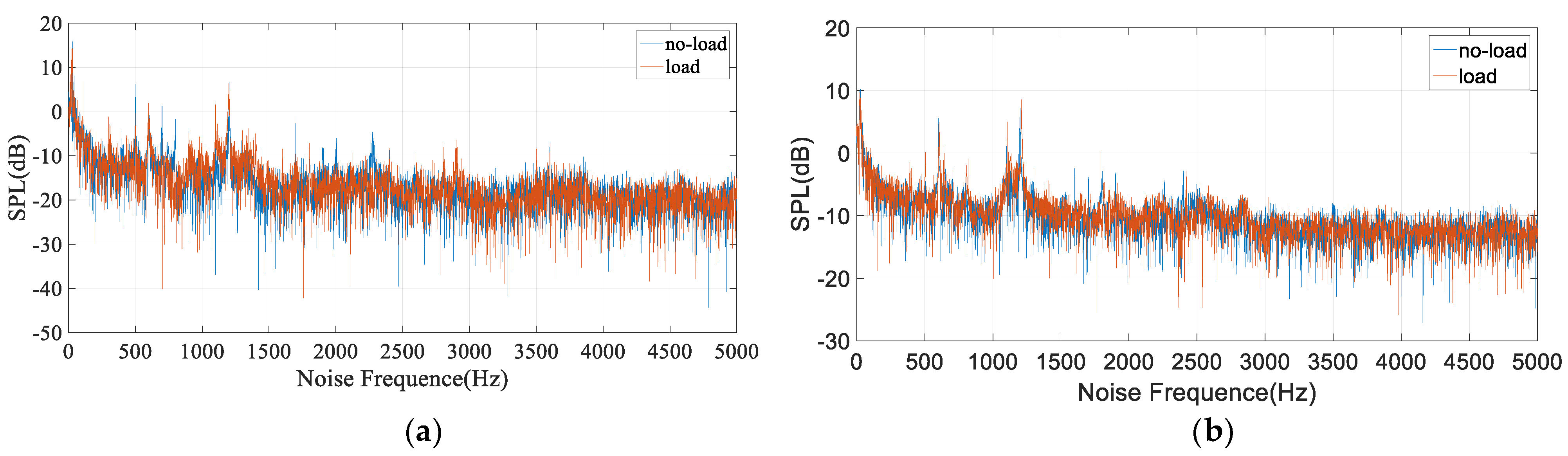
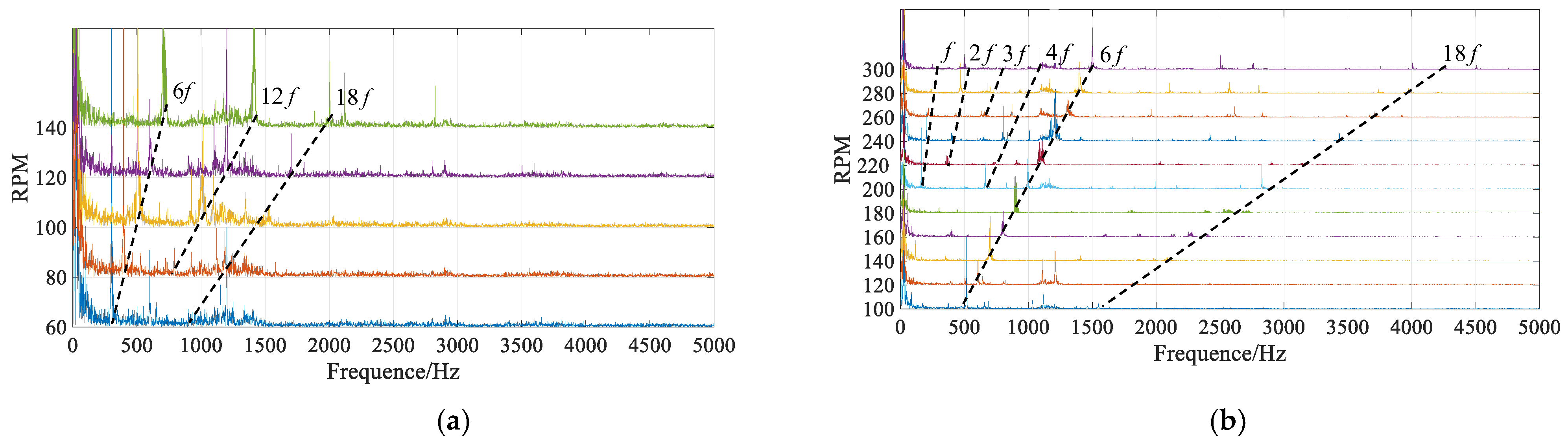
4.1. Noise Analysis

The relationship between the rotating speed of the stepper motor n and the frequency of the drive current f1 is,
f 1 = p × n 60
In the operation, the stepper motor is energized and operated in a certain logic state according to the pulse of the control signal [30,31]. Therefore, the pulse frequency fcp of the control signal and the current frequency have the following relationship:
f c p = N × f i
where, N is an integer of a multiple of 6, i.e., the number of pulses for the 3P-HSM to rotate a tooth pitch.
From Equations (1) and (22), the EM torque generated by the drive current should have the same fundamental frequency of the drive current, and the torque ripples that are integer multiples of the fundamental frequency should also be accompanied by the current. For the same reason, the noise at the frequency point of Equation (23) should also be pronounced in the motor operation.
In addition, there is another EM cycle in the operation of the motor: the switching cycle of power semiconductors, and it is also known as a chopping cycle [32]. It is determined by the design of the controller and is independent to the motor speed. However, the chopping affects the current waveform to a certain level, and the noise spectrum should contain the information of the chopping.

4.2. Loss Analysis

It was mentioned that the hybrid stepper motor can be classified as a PMSM, and the losses of this kind of motor are mainly divided into winding copper loss, mechanical loss, and motor iron loss [33].
Winding copper loss, pcu, refers to the loss of motor winding caused by resistance. When the phase current is sinusoidal, it can be expressed as:
p c u = m I 2 R
where, m is the number of motor phases; I is the effective value of the phase current, R is the phase winding resistance. It can be seen from Equation (24) that pcu is related to the winding current and resistance. In order to simplify the analysis, the winding resistance is assumed to be constant. pcu of the motor is thus related to the control modes as a different mode could generate a different current for the same load.
The mechanical loss of a motor is mainly divided into two parts: windage loss and friction loss. The former is caused by the windage between the rotor and the surrounding air of the rotor during the operation of the motor; the latter is caused by friction between the stationary and rotating parts of the bearing. Motor iron loss is the eddy current loss generated in the iron core due to the variation of the motor magnetic field and the loss caused by the hysteresis effect in the iron core [33]. The iron loss is mainly affected by motor structure, silicon steel sheet used, and installation quality, and is not related to the control mode [34]. In this paper, one of the focuses is analyzing the impact of the control mode on motor loss, i.e., the impact on copper loss.

4.3. Pullout Torque Analysis

The torque that can effectively drive the maximum load at the same speed is known as the pullout torque of a stepper motor. Therefore, it is desirable to have a stepper motor with a large pullout torque over a wide speed range. This is because when there is a sudden change in load torque, the motor will be unstable if the pullout torque of the motor is not sufficient, resulting in a constantly increasing difference between load torque and motor torque, which will eventually cause the motor to be out-of-step [35]. To ensure that a stepper motor can be operated safely, the motor must be driven at a considerable current to produce a sufficiently high torque, and this inevitably causes large cupper loss.
Increasing the speed of the stepper motor, the EM torque of the motor will decrease during subdivision operation [35,36]. The main reasons include:
(1)
High speed means the high frequency of current. Due to the effect of inductance, the winding current rises relatively slowly in an electric cycle when the frequency is increased, and the effective value of the current is thus reduced. Therefore, the average EM torque of the motor is reduced.
(2)
The winding back-emf is increased with the increase of speed, which limits the current rising ability during open-loop operation.
If the stator magnetic field can be adjusted appropriately to change its relative position with the rotor for making the motor run in its stable region, the phenomenon of out-of-step can be avoided [17]. FOC mode has such an ability. Using this control mode, the controller detects the relative position of the rotor through the sensored or sensorless method to ensure that the rotor is in the stable region and tries to optimize the difference angle between the stator and rotor fields. In this way, the motor can operate stably. Therefore, FOC mode can effectively improve the pullout torque of the motor.

5. Motor Test

Figure 7 illustrates the EM structure of the motor used for the experiment. In order to verify the effects of the sensorless FOC mode, the test platform shown in Figure 8 was designed and built. In the experiment, the RTI1202 control platform of dSPACE company was used. The motor and load were put in an acoustic chamber and the microphone was connected to the host computer through the sound card for detecting the motor noise. The acoustic noises at different motor speeds were recorded and their spectra were analyzed. The equipment shown in Table 1 were used in the platform. Table 2 shows the main indicators of the 3P-HSM used in the test.

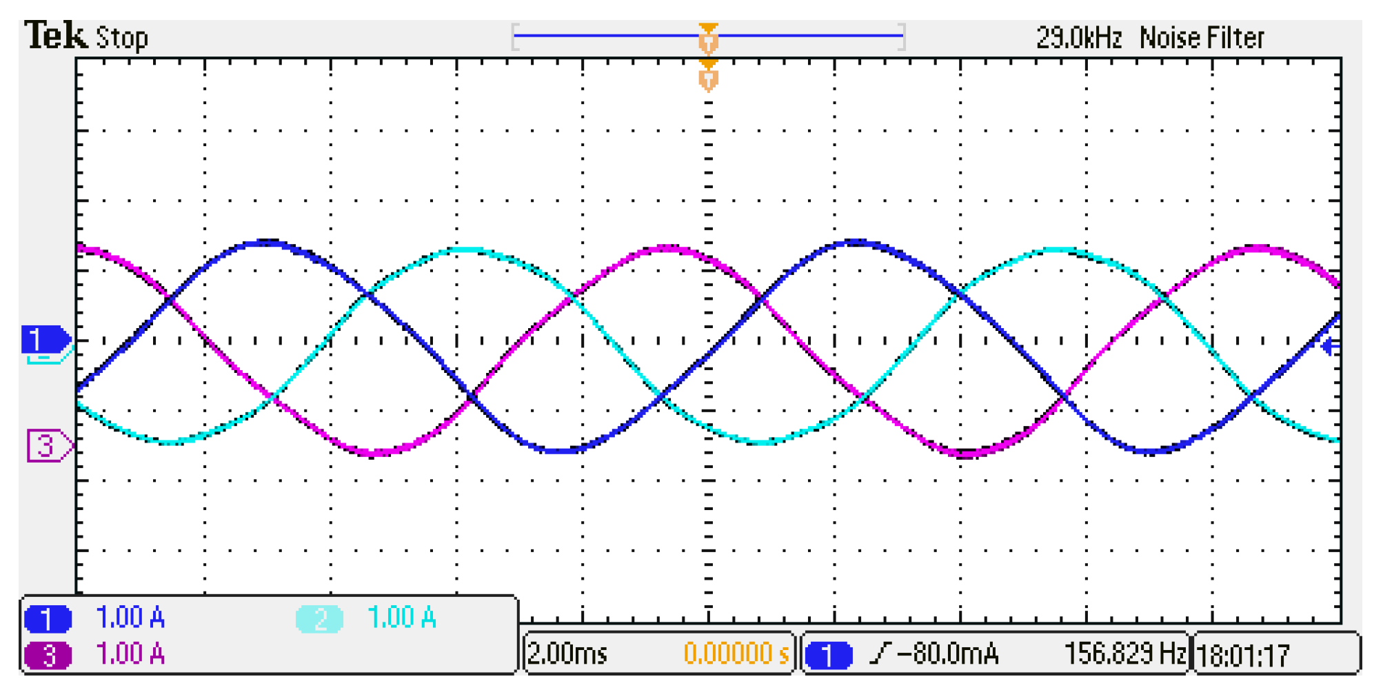
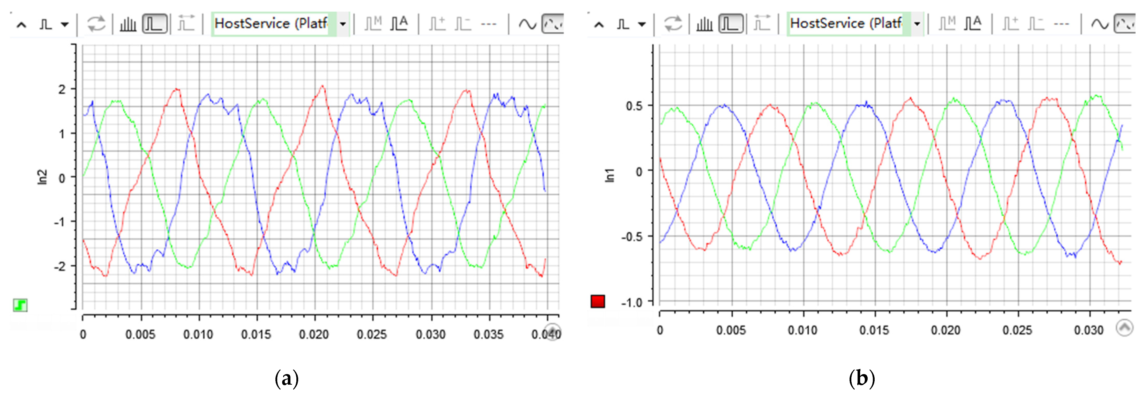
5.1. Control Current

The current waveforms of the 3P-HSM at 120 rpm are shown in Figure 9.
It can be seen from the Figure 9 that when the stepper motor is running in half-step subdivision mode, its stator current contains rich harmonics, and the motor thus easily enters the “out-of-step” state [37]. To ensure that the motor is in step, the controller has to use a large current to increase the amplitude of the motor’s TAC and cause the rotor to be located in the stable region. This certainly induces large copper loss and EM noise in motor operation. With the FOC mode, the drive current is sinusoidal, when the stator field is orthogonal to rotor field the current can be much smaller than the subdivision mode, and all of these factors are important to reduce the copper loss and acoustic noise.

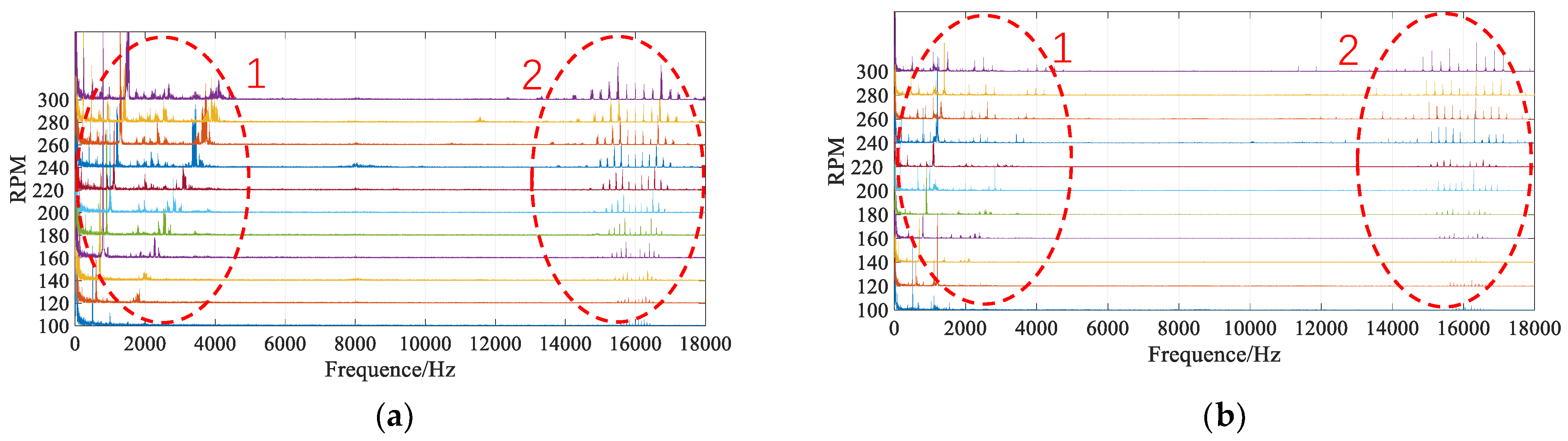
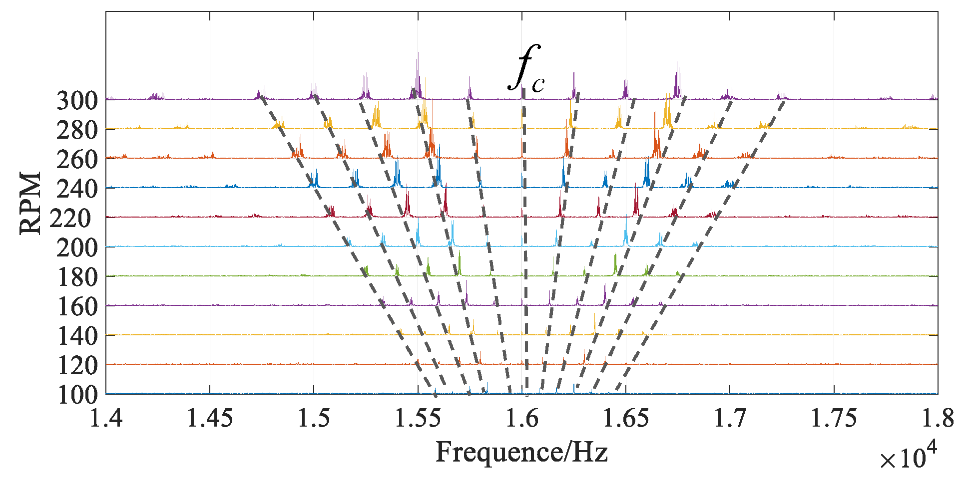
5.2. Noise Analysis with a Waterfall Plot

A waterfall plot is an effective tool for analyzing the vibration and noise of rotating machinery. It superimposes the noise spectrum of different speeds into a plot to disclose the relationship between the noise source and frequency spectra [33].
In the test, a host computer collected and analyzed the noise data of the 3P-HSM, and built the noise waterfall plot of the motor. The waterfall plot for different control modes and loading states is shown in Figure 10. In the plot, the noise is classified as low frequency oscillation noise and harmonic noise part (ellipse-1) and chopping frequency part (ellipse-2).
From Figure 10, in the low-frequency region, there is a lot of noise closing the ordinate axis in the operation with both control modes. This part of the noise is chaotic and related to the mechanical structure of the motor and the test environment [38]. This part of the noise is basically independent of the drive mode.
Figure 11 shows the noise induced by the current in idle and loaded operations. Taking the results under 120 rpm as an example, the following conclusions can be obtained:
(1) Under the half-step subdivision mode, with the influence of the drive current with a square wave the rotor does not run smoothly (see Figure 11a). The spectrum of the noise at 120 rpm, and other speeds, contains many burrs. The vibration is obvious and the noise amplitude is relatively large at many frequency points, especially at the points of the 6th, 12th, and 18th multiples of the current frequency. From Equation (22), the fundamental current frequency at 120 rpm is
f 1 = 50 × 120 60 = 100 Hz
all of the noise related to the current is indicated by the dotted line in Figure 11b.
(2) Under the sensorless FOC, the motor drive current is also sinusoidal and symmetric. Since the EM torque of the motor is generated with the overall EM effect of the motor, the sensorless FOC can adjust the angle between the stator and rotor fields with global EM effect, and this is more meaningful to the EM torque generation. In the waterfall plot shown in Figure 11b, the noise burr is significantly reduced, and the amplitude of the noise is also reduced significantly at many spectrum points, especially in the high frequency region.
Comparing the waterfall plots under different modes, it can be seen that the EM torque ripples are strong under the half-step subdivision mode, as its current harmonics are rich, and large drive current has to be used in this control mode. As a comparison, the noise can be reduced significantly in the use of the sensorless FOC mode.
Figure 12 shows the effects of chopping frequency on the waterfall. The dotted line at 16.2 kHz represents the PWM chopping frequency of the controller used in the test. As mentioned above, the chopping frequency is determined by the controller’s own characteristics, and not linked to the motor speed and control mode. Therefore, the chopping line exists in all of the waterfall plots built from the experiment data. The influence of the chopping can be found from the mirrored lines around the chopping line [39,40]. In addition, in the sensorless FOC mode, with the decrease of harmonics drive current, it can be seen that the noise is reduced obviously in many points of the multiple frequencies of the current. The waterfall shows also that, for the applications that are sensitive to the acoustic effects of chopping noise, the PWM should be processed with a frequency higher than audible range, i.e., higher than 20 kHz.
Figure 13 shows the comparison of Sound Pressure Levels (SPLs) of the motor noise in idle operation under different control modes. Under the half-step subdivision mode, the motor is always driven by the step-like current, and the harmonics of the current are much stronger than that of FOC, resulting in the increase of motor noise. Under the sensorless FOC mode, the motor is driven by sinusoidal current, and the current harmonics are much weaker than that of half-step subdivision mode. From the plots, it can thus be found that SPLs of the motor noise induced by the sensorless FOC mode are significantly lower than the ones induced by the half-step subdivision.
Figure 14 shows the comparison of SPL in loaded operation under two control modes. A stepper motor is used as the actuator in the position control, and its load can certainly affect the drive current and control effect of the motor. For the half-step subdivision mode, when the load is increased, the rotor gradually moves to the unstable region. In order to ensure the motor operates in stable state, the controller must drive the motor with large current to increase the amplitude of the TAC, and the by-products of this measure ensure that both the noise and loss of the motor are increased. The FOC mode can adjust the field angle during motor operation timely to maximize the EM torque per unit current and ensure the operation of the motor in stable state. In addition, under the sensorless FOC, the field angle can be adjusted more accurately with the global EM effect of the motor. Therefore, both the noise SPL and copper loss can be reduced with the sensorless FOC mode in the motor operation.
Figure 15 shows the noise waterfall of two control modes under idle and load conditions at 120 rpm. It can be seen from the figure that the noise in idle operation is lower than the loaded operation for the same control mode. Due to the rich harmonics and larger current, the half-step mode is always the worst in the noise generation, and the sensorless FOC is the best.

5.3. Motor Copper Loss Analysis

For a given motor, the copper loss generated in its operation is always an important index to judge the performance of the controller. Table 3 and Table 4 show the effective values of the drive current and copper losses in idle and loaded (0.14 Nm) operations under the two control modes, and the motor speeds are controlled at 120 rpm. The effective value of the current Ieff is obtained by using the following equation,
I e f f = 1 N k = 1 N i k 2
where, ik is the transient phase current sampled in the test, and N is the sampling number in one current cycle.
In Table 3 and Table 4, the results of half-step subdivision mode are used as the benchmark. The tables show that the sensorless FOC modes can reduce the drive current and copper loss significantly. Taking the loaded operation, for example, 70.6% of the drive current and 91.4% of copper loss can be reduced with the use of the sensorless FOC mode. Reducing the drive current is important to reduce the current redundancy of the controller, and the cost of the controller can therefore be reduced. Copper loss is not only related to the efficiency of the motor system, but also related to the heating, and further to the health, of the motor.

5.4. The Maximum Speed of the Motor

Whether the motor is running in idle or loaded condition, its maximum speed is closely related to the motor’s “pullout torque”. This torque is difficult to detect with the direct torque measurement as the pullout torque is sensitive to the moment of inertia and friction of torque transducer. In order to explore the influence of the control mode on the pullout torque, the maximum speeds of 3P-HSM under the different modes were tested in the authors’ research and the results are shown in Table 5 and Table 6.
It can be seen from the table that, whether the motor is running idle or load state, the maximum speed of the motor under the sensorless FOC mode is significantly higher than that of subdivision mode. The voltage of the control system is 24 V. It can be found from the tables that the maximum speed of the motor under the sensorless FOC mode is about 3.4 times that of the half-step subdivision mode. The results reflect that the sensorless FOC can always keep the angle between the rotor and stator fields in a stable region, and the pullout torque of 3P-HSM can thus be increased, until the back-emf of winding rises to the point where the controller loses the effective regulation of the drive current.

6. Conclusions

The performance of 3P-HSM is not only related to its EM structure and materials used, but also closely related to its control mode. From the published literature, the study on the drive mode of this kind of motor is essentially based on the open-loop control mode. Since this control mode cannot significantly improve the performance of stepper motor, this paper presented a “position sensorless closed-loop” control mode to greatly improve the performance of 3P-HSM in steady-state operation. In order to realize the “sensorless closed-loop” control, “EKF position observer” was presented to estimate the rotor position of the motor, and then realize the closed-loop control of 3P-HSM. In the paper, the testing results on the noise, copper consumption, and maximum speed of the motor under different control modes were analyzed. The results show that the “EKF position observer” has high accuracy and is suitable for the closed-loop control of 3P-HSM. The testing results showed that the sensorless closed-loop control mode presented can reduce the EM torque ripple of the motor in a wide speed range, and the running noise of the motor can also be reduced significantly, especially the high-order harmonic noise. In terms of losses, the copper consumption of the motor in the sensorless closed-loop control mode is only 4~8.6% of that in the open-loop operation, which is of great significance to save energy and prolong the service life of the motor. In addition, the sensorless closed-loop control mode can ensure that the difference angle of the global stator and rotor magnetic field of the motor remain orthogonal, which can make the motor run steadily, and greatly improve the pullout torque and maximum speed of the motor. Because there is no need to install additional physical sensors on the motor, the sensorless closed-loop mode has great advantages in terms of cost and size control. These are very important for broadening the application of 3P-HSM.

Author Contributions

All authors have made significant contributions to this manuscript. Conceptualization, Z.P.; Data curation, Z.P.; Formal analysis, Z.P.; Investigation, Z.P.; Methodology, Z.P.; Resources, C.B.; Validation, Z.P.; Writing—original draft, Z.P.; Writing—review and editing, C.B. All authors have read and agreed to the published version of the manuscript.

Funding

This research received no external funding.

Institutional Review Board Statement

Not applicable.

Informed Consent Statement

Not applicable.

Data Availability Statement

Not applicable.

Acknowledgments

We acknowledge the support and the use of the facilities and equipment provided by the China Fortior Technology (Shenzhen) Co., Ltd.

Conflicts of Interest

The authors declare no conflict of interest.

References

  1. Peng, Z.; Bi, C. Analysis of Drive Mode on Torque and Noise of Stepper Motor. Micromotors 2019, 52, 27–31. (In Chinese) [Google Scholar]
  2. Chen, L.; Yan, Z.; Liu, X. Control Motor; Xidian University Press: Xi’an, China, 2013; pp. 245–247. (In Chinese) [Google Scholar]
  3. Ma, X.; Bi, C. A technology for online parameter identification of permanent magnet synchronous motor. China Electrotech. Soc. Trans. Electr. Mach. Syst. 2020, 4, 237–242. [Google Scholar] [CrossRef]
  4. Peng, Z.; Bi, C.; Yao, K.; Fang, L. Reducing acoustic noise of 3-phase hybrid stepper motor with drive mode. Electr. Eng. 2021, 103, 1–9. [Google Scholar] [CrossRef]
  5. Sarr, M.P.; Ndiaye, M.F.; Dieng, B.; Thiam, A. Field oriented control of stepper motors for a mini heliostat tracking. In Proceedings of the 2021 IEEE 1st International Maghreb Meeting of the Conference on Sciences and Techniques of Automatic Control and Computer Engineering MI-STA, Tripoli, Libya, 25–27 May 2021; pp. 104–109. [Google Scholar] [CrossRef]
  6. Son, H.U.; Jeong, Y.W.; Chung, C.C. Position Estimation of Stepping Motor Using Adaptive Gain Super Twisting Algorithm Sliding Mode Observer. In Proceedings of the 2021 21st International Conference on Control, Automation and Systems (ICCAS), Jeju, Korea, 12–15 October 2021; pp. 566–570. [Google Scholar] [CrossRef]
  7. Bi, C.; Lin, S. Analysis of acoustic noise sources of FDB and ADB spindle motors operating at BLDC mode. In Proceedings of the 4th International Conference on Power Electronics, Machines and Drives, York, UK, 2–4 April 2008. [Google Scholar]
  8. Lin, S.; Jiang, Q.; Mamun, A.A. Effect of Drive Modes on the Acoustic Noise of Fluid Dynamic Bearing Spindle Motors. IEEE Trans. Magn. 2003, 39, 3277–3279. [Google Scholar] [CrossRef]
  9. Pindoriya, R.M.; Rajpurohit, B.S.; Kumar, R. A Novel Application of Harmonics Spread Spectrum Technique for Acoustic Noise and Vibration Reduction of PMSM Drive. IEEE Access 2020, 8, 103273–103284. [Google Scholar] [CrossRef]
  10. Tang, M.; Odhano, S.; Formentini, A.; Zanchetta, P. Reuse of a Damaged Permanent Magnet Synchronous Motor for Torque Ripple and Acoustic Noise Elimination Using a Novel Repetitive Observer. IEEE Trans. Ind. Appl. 2020, 56, 3790–3798. [Google Scholar] [CrossRef] [Green Version]
  11. Li, G.-J.; Liang, X.-B.; Zhu, Z.-Q.; Ojeda, J.; Gabsi, M. Vibrations and Acoustic Noise Analyses of Modular SPM Machines. In Proceedings of the 2020 IEEE Energy Conversion Congress and Exposition (ECCE), Detroit, MI, USA, 11–15 October 2020; pp. 5567–5573. [Google Scholar]
  12. Xiangjun, T. Learn NVH: Noise, Vibration and Harshness; Machine Press: Beijing, China, 2018; pp. 209–226. (In Chinese) [Google Scholar]
  13. Wang, Y.; Tian, Y.; Wang, Z. Analysis of Harmonic Electromagnetic Torques of Hybrid Stepping Motors. Trans. China Electrotech. Soc. 2002, 17, 17–20. (In Chinese) [Google Scholar]
  14. Yu, Y.; Chai, F.; Cheng, S. Analysis of modulation pattern and losses in inverter for PMSM drives. In Proceedings of the 2008 IEEE Vehicle Power and Propulsion Conference, Harbin, China, 3–5 September 2008; pp. 1–4. [Google Scholar]
  15. Chengyuan, W.; Jiakuan, X.; Yibiao, S. Modern Motor Control Technology; Machine Press: Beijing, China, 2014. (In Chinese) [Google Scholar]
  16. de Viaene, J.; Ceulemans, D.; Derammelaere, S.; Haemers, M.; Stockman, K. Improved dynamic behaviour of a sensorless stepping motor load angle estimator based on Transfer Function Analyzer technique. In Proceedings of the 2021 23rd European Conference on Power Electronics and Applications (EPE’21 ECCE Europe), Ghent, Belgium, 6–10 September 2021; pp. 1–10. [Google Scholar]
  17. Yunmiu, T. Electrical Machinery; Machine Press: Beijing, China, 2014; pp. 283–285. (In Chinese) [Google Scholar]
  18. Apte, A.; Joshi, V.A.; Mehta, H.; Walambe, R. Disturbance-Observer-Based Sensorless Control of PMSM Using Integral State Feedback Controller. IEEE Trans. Power Electron. 2019, 35, 6082–6090. [Google Scholar] [CrossRef]
  19. Zhu, Z.Q.; Howe, D. Electrical Machines and Drives for Electric, Hybrid, and Fuel Cell Vehicles. Proc. IEEE 2007, 95, 746–765. [Google Scholar] [CrossRef]
  20. Li, Z. Study on driving system of three-phase hybrid stepping motor. In Proceedings of the Sixth International Conference on Electrical Machines and Systems, Beijing, China, 9–11 November 2003. [Google Scholar]
  21. Ton, T.-D.; Hsieh, M.-F.; Chen, P.-H. A Novel Robust Sensorless Technique for Field-Oriented Control Drive of Permanent Magnet Synchronous Motor. IEEE Access 2021, 9, 100882–100894. [Google Scholar] [CrossRef]
  22. Podder, A.; Pandit, D. Study of Sensorless Field-Oriented Control of SPMSM Using Rotor Flux Observer & Disturbance Observer Based Discrete Sliding Mode Observer. In Proceedings of the 2021 IEEE 22nd Workshop on Control and Modelling of Power Electronics (COMPEL), Cartagena, Colombia, 2–5 November 2021; pp. 1–8. [Google Scholar] [CrossRef]
  23. Tang, X.; Zhang, Z.; Liu, C.; Zhang, M.; Liu, X.; Jiang, M.; Zhang, Z. The Field-Orientated-Control Algorithm for Permanent Magnet Synchronous Motor in 60° Coordinate System. In Proceedings of the 2021 24th International Conference on Electrical Machines and Systems (ICEMS), Gyeongju, Korea, 31 October–3 November 2021; pp. 1829–1832. [Google Scholar] [CrossRef]
  24. Bae, J.; Lee, D. Position Control of a Rail Guided Mover Using a Low-Cost BLDC Motor. IEEE Trans. Ind. Appl. 2018, 54, 2392–2399. [Google Scholar] [CrossRef]
  25. Tang, Z.; Akin, B. A New LMS Algorithm Based Deadtime Compensation Method for PMSM FOC Drives. IEEE Trans. Ind. Appl. 2018, 54, 6472–6484. [Google Scholar] [CrossRef]
  26. Zhurov; Bayda, S.; Florentsev, S. Field-Oriented Control of the Cargo Locomotive Induction Motor Electric Drive When Using Single Power Converter Feeding Two Traction Motors. In Proceedings of the 2021 International Conference on Electrotechnical Complexes and Systems (ICOECS), Ufa, Russian Federation, 16–18 November 2021 ; pp. 37–42. [Google Scholar] [CrossRef]
  27. Wang, Z.; Chen, J.; Cheng, M.; Chau, K.T. Field-Oriented Control and Direct Torque Control for Paralleled VSIs Fed PMSM Drives with Variable Switching Frequencies. IEEE Trans. Power Electron. 2015, 31, 2417–2428. [Google Scholar] [CrossRef]
  28. Luo, P.; Xu, J.; Liu, H.; Huang, H.; Yang, Y.; Yu, Y. An Integrated Vector Control Strategy for BLDC Current. In Proceedings of the 2019 IEEE 3rd Information Technology, Networking, Electronic and Automation Control Conference (ITNEC), Chengdu, China, 15–17 March 2019; pp. 1666–1670. [Google Scholar]
  29. Cui, B.; Fang, L.L.; Jiang, Q.; Bi, C. A Comparative Study of High-Speed Position Sensorless Control Technology in Surface Mounted Permanent Magnet Synchronous Motors. Electron. Sci. Technol. 2021, 34, 8–17. (In Chinese) [Google Scholar]
  30. Bi, C.; Phyu, H.N.; Jiang, Q. Unbalanced magnetic pull induced by leading wires of permanent magnet synchronous motor. In Proceedings of the 2009 International Conference on Electrical Machines and Systems, Tokio, Japan, 15–18 November 2009. [Google Scholar]
  31. Pindoriya, R.M.; Gautam, G.; Rajpurohit, B.S. A Novel Application of Pseudorandom-Based Technique for Acoustic Noise and Vibration Reduction of PMSM Drive. IEEE Trans. Ind. Appl. 2020, 56, 5511–5522. [Google Scholar] [CrossRef]
  32. Odabaşı, T.; Tap, A.; Ergene, L.T. Simulation and Design of a Sensorless FOC Driver for a PMSM used in Compressor. In Proceedings of the 2021 3rd Global Power, Energy and Communication Conference (GPECOM), Antalya, Turkey, 5–8 October 2021; pp. 97–102. [Google Scholar] [CrossRef]
  33. Lixiang, S.; Xiaoyan, Z. Loss Analysis of Permanent Magnet Synchronous Motor. Electr. Technol. 2019, 20, 158–161. (In Chinese) [Google Scholar]
  34. Rong, X. Loss analysis and temperature calculation of permanent magnet synchronous motor. Shanghai SDJJ 2017, 8, 8–15. (In Chinese) [Google Scholar]
  35. Acarnley, P. Stepping Motors: A Guide to Modern Theory and Practice; IET: London, UK, 2002; pp. 41–58. [Google Scholar]
  36. Russell, A.; Pickup, I. A circuital method for the prediction of pull-out torque characteristics of hybrid stepping motors. IEE Proc. B Electr. Power Appl. 1982, 129, 330–336. [Google Scholar] [CrossRef]
  37. Kangning, C.U.I.; Shenbo, Y.U.; Rutong, D.O.U.; Pengpeng, X.I.A. Reduction Method of Torque Ripple and Vibration and Noise of Permanent Magnet Synchronous Motor. Micromotors 2020, 53, 11–16. [Google Scholar]
  38. Vijayraghavan, P.; Krishnan, R. Noise in electric machines: A review. IEEE Trans. Ind. Appl. 1999, 35, 1007–1013. [Google Scholar] [CrossRef]
  39. Guan, Q.; Liu, J.; Zhou, Y.; Qiu, H. The Vector Control Research and Implementation of the Three-Phase Hybrid Stepping Motor. In Proceedings of the 2016 International Conference on Industrial Informatics—Computing Technology, Intelligent Technology, Industrial Information Integration (ICIICII), Wuhan, China, 3–4 December 2016; pp. 384–387. [Google Scholar]
  40. Pantano, M.N.; Puchol, M.C.F.; Rossomando, F.G.; Scaglia, G.J.E. Open-Loop Dynamic Optimization for Nonlinear Multi-Input Systems. Application to Recombinant Protein Production. IEEE Latin Am. Trans. 2021, 19, 1307–1314. [Google Scholar] [CrossRef]
Figure 1. Testing result: the TAC of the motor.
Energies 15 00804 g001
Figure 2. Testing result: the line inductance curve of the 3P-HSM.
Energies 15 00804 g002
Figure 3. Testing result: the line back-emf of the 3P-HSM.
Energies 15 00804 g003
Figure 4. The overall control diagram of SCLC mode for the constant speed control.
Energies 15 00804 g004
Figure 5. Testing result: current waveform of FOC mode.
Energies 15 00804 g005
Figure 6. Motor rotor position.
Energies 15 00804 g006
Figure 7. The EM structure of the motor. (a) The stator model of the 3P-HSM with 12 slots. (b) The rotor model.
Energies 15 00804 g007
Figure 8. The experimental system: (a) the outside of the testing system; (b) the inside of the acoustic chamber.
Energies 15 00804 g008
Figure 9. Testing result: the waveform of the drive current: (a) half-step subdivision mode in the loaded operation; (b) sensorless FOC mode in the loaded operation.
Energies 15 00804 g009
Figure 10. Testing results. Waterfall of the acoustic noise of the motor: (a) half-step subdivision mode in loaded operation; (b) sensorless FOC mode in loaded operation.
Energies 15 00804 g010
Figure 11. Testing results. The effects of current harmonics on the waterfall: (a) half-step subdivision mode in loaded operation; (b) sensorless FOC mode in loaded operation.
Energies 15 00804 g011
Figure 12. Testing result: the effects of chopping frequency on the waterfall.
Energies 15 00804 g012
Figure 13. Testing result: the SPL spectrum of the motor at 120 rpm idle operation.
Energies 15 00804 g013
Figure 14. Testing result: the SPL spectrum of the motor at 120 rpm loaded operation.
Energies 15 00804 g014
Figure 15. Comparison of SPL spectra of idle and loaded motors: (a) 120 rpm SPL under half-step subdivision mode; (b) 120 rpm SPL under sensorless FOC mode.
Energies 15 00804 g015
Table 1. The test equipment type.
Test EquipmentCompanyType
ControllerdSPACERTI1202
Sound cardiCONMicU
MicrophoneBehringerECM8000
Decibel meterAihuaAWA5661
Table 2. The test motor parameters.
ParametersValues
Rated current (Amp)5.8
Holding torque (Nm)1.4
Phase resistance (ohm)4.13
Phase inductance (mH)10.7
Rotor inertia (g·cm2)460
Back-emf (V/1000 rpm)46.2
Table 3. Copper loss in idle operation.
IdlePhase Current/ARatioCopper Loss/WRatio
Sensorless FOC0.320%1.1074%
Half-step subdivision1.5100%27.675100%
Table 4. Copper loss in loaded operation.
Load (0.14 Nm)Phase Current/ARatioCopper Loss/WRatio
Sensorless FOC0.529.4%3.0758.6%
Half-step subdivision1.7100%35.55100%
Table 5. The maximum speed in idle operation.
Operating StatesMax Speed/rpmPhase Current/A
Half-step for idle1851.5
Sensorless FOC for idle6700.3
Table 6. The maximum speed in loaded operation.
Operating StatesMax Speed/rpmPhase Current/A
Half-step for load
(0.14 Nm)
1531.7
Sensorless FOC for load
(0.14 Nm)
6300.5
Publisher’s Note: MDPI stays neutral with regard to jurisdictional claims in published maps and institutional affiliations.

