Article

Analysis and Cogging Torque Minimization of a Novel Flux Reversal Claw Pole Machine with Soft Magnetic Composite Cores

1
State Key Laboratory of Reliability and Intelligence of Electrical Equipment, Hebei University of Technology, Tianjin 300130, China
2
Key Laboratory of Electromagnetic Field and Electrical Apparatus Reliability of Hebei Province, Hebei University of Technology, Tianjin 300130, China
*
Author to whom correspondence should be addressed.
Energies 2022, 15(4), 1285; https://doi.org/10.3390/en15041285
Submission received: 27 December 2021 / Revised: 28 January 2022 / Accepted: 29 January 2022 / Published: 10 February 2022
(This article belongs to the Special Issue Advanced Electrical Machine Design and Optimization)

Abstract

:
The performances of a novel flux reversal claw pole machine (FRCPM) using soft magnetic composite (SMC) cores is analyzed in detail. The developed FRCPM uses both a flux reversal permanent magnet machine (FRPMM) and claw pole machine (CPM). In this paper, the main dimensions are optimized to ensure that the FRCPM can achieve maximum torque. In addition, the rotor skewing technology applied in the paper leads to a reduction in cogging torque and torque ripple of the machine. The main electromagnetic parameters and performance are obtained using the 3D finite element method.

1. Introduction

As a special kind of permanent magnet machine, flux reversal permanent magnet machines (FRPMM) have a particular topology: the permanent magnets (PM) and windings are both located on the stator side of the machine, while the rotor side only has an iron core [1,2,3,4]. Such structure displays some advantages, such as high torque, high fault tolerance, and mechanical robustness. Consequently, the FRPMM is considered a promising driving machine in applications of electric vehicles, power generations, and subways [5,6,7]. In recent years, a great number of attempts have been made to improve the performance of FRPMM, including the use of distributed windings to increase the power density [8] and the new even-distributed PMs to improve the torque. Some techniques, such as rotor skewing, stator skewing, and rotor pole pairing rotor teeth shaping, are also employed to reduce the torque ripple and cogging torque [9,10,11].
As a special member of transverse flux machines (TFM), the claw pole machines (CPM) adopt the structure of the claw pole teeth, which is currently fabricated from the soft magnetic composite (SMC). As a result, its torque and power factor are significantly improved compared with TFM [12,13,14]. With the rapid development of SMC, the applications of the CPM will be extended significantly.
The SMC materials are synthesized from iron powder coated with an insulating layer by powder metallurgy technology. It has high resistivity compared with silicon steels. Together with isotropic magnetic and thermal characteristics, the low material consumption of the rotor, and stator fabrications, it shows superior performance, for example, low core loss, in the high-frequency range in particular [15,16,17,18,19].
This paper will focus on the optimization of a new flux reversal claw pole machine (FRCPM) with SMC cores to weaken its cogging torque and torque ripple. Table 1 shows a clear comparison of the above three kinds of motors [20,21]. The FRCPM has the three-dimensional magnetic circuit of CPM, and at the same time, the permanent magnet is transferred to the stator so that the rotor is as robust as FRPMM. The proposed FRCPM can have the merits of both FRPMM and CPM with SMC cores, including high torque, high fault tolerance, high power factor, and mechanical robustness. The commercial 3D finite element method (FEM) package Maxwell 3D analyzes the parameter and performance. The paper is organized as follows. First, the main dimensions and parameters are optimized. Second, the main parameters and performance of FRCPM are obtained. Third, the cogging torque and torque ripple are minimized by using the rotor skewing method. Lastly, some conclusions are drawn.

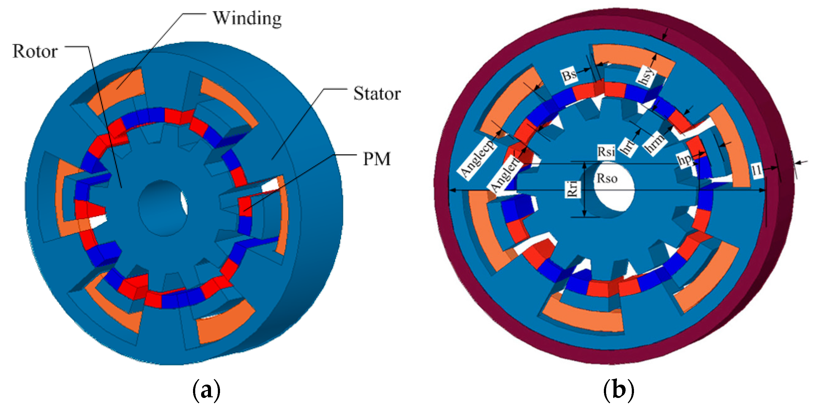
2. Topology of FRCPM

To clearly show the topology of the three-phase FRCPM studied in this paper, Figure 1a only shows the schematic one-phase topology. Every phase of FRCPM has been shifted with a determined degree to form the symmetrical three-phase operation. The main stator core fabricated from SMC and global ring winding is quite similar to CPM’s. The PMs are attached to the surface of stator claw pole teeth in FRCPM, while they are attached to the rotor core in CPM. The magnetization direction of PMs in FRCPM is along the radial direction. Two magnets are attached to the teeth. They are placed close together, but the magnetization directions are opposite. Two close PMs with opposite directions are also attached to the adjacent claw pole (or teeth) in such an order so that the adjacent two PMs, attached to the adjacent poles, have the same directions. The rotor core is made from stacked silicon steel with no windings and PMs. Therefore, the mechanical structure is very robust and satisfies the high-speed requirements. Figure 1b shows the main dimensions of FRCPM. The electromagnetic torque of FRCPM can be expressed as [14]:
T e m = C T R s i L 1 ( L 1 2 B s ) ( R s o R r o h s y h p h r m ) J m
where
C T = 0.5 π N s m K s p K c K d B g k s f
where L1 is the effective axial length for the one-phase model, m is the number of phases, Bs is the stator tooth length in the axial direction, Rso is the stator outer radius, Rsi is the stator inner radius, hsy is the length of stator yoke, hp is the thickness of stator claw pole, hrm is the thickness of magnets, Ns is the number of stator poles, Ksp is the ratio of stator tooth width to pole arc, Kc is the winding factor, Kd is the flux leakage coefficient, Bg is the air gap flux density, and ksf is the slot fill factor.

3. Design Optimization

From the power equations for FRCPM, it can be seen that the electrical load and magnetic load should be balanced to achieve the best performance by altering the two parameters, i.e., the thickness of the stator wall, Bs, and the inner radius of the stator core, Rsi. In this study, the electromagnetic (EM) torque is regarded as the most important output. In FRCPM, the pole ratio of the stator claw pole width to pole pitch, k, and the height of the rotor teeth, hrt, can affect the distributions of the magnetic flux density in the air gap since both the leakage flux and effective flux are strongly dependent on k and hrt. The pole ratio and the height of the rotor teeth can be optimized after optimizing the thickness of the stator wall and the inner radius of the stator core.
Figure 2 shows the optimization process of the thickness of the stator wall and the inner radius of the stator core. It can be seen that the achievement of a greater EM torque requires a thinner stator wall. Taking the mechanical strength of the stator wall into account, the minimum thickness is set to 4 mm. The mechanical strength of the stator wall will be much lower and even unacceptable if it is less than 4 mm. Correspondingly, the inner stator radius is between 20.5 mm and 23 mm. In addition, the core loss increases when decreasing the inner radius of the stator core, as shown in Figure 2b. Based on the analysis of the factors, the inner radius of the stator core of 22.5 mm is adopted. Thus, the EM torque of the designed machine could be 0.09 Nm, and the core loss is around 3.8 W.
Figure 3 shows the design optimization of the pole ratio and the height of rotor teeth. It can be seen that there are five regions to reach the maximum torque. However, the core loss will increase with an increase in the pole ratio. Thus, the lower ratio, the better the overall performance. For the developed FRCPM, k is set to be 0.8 and hrt 4 mm. After the design optimization, the main parameters and dimension of FRCPM are given in Table 2, based on which the performance of FRCPM are calculated.

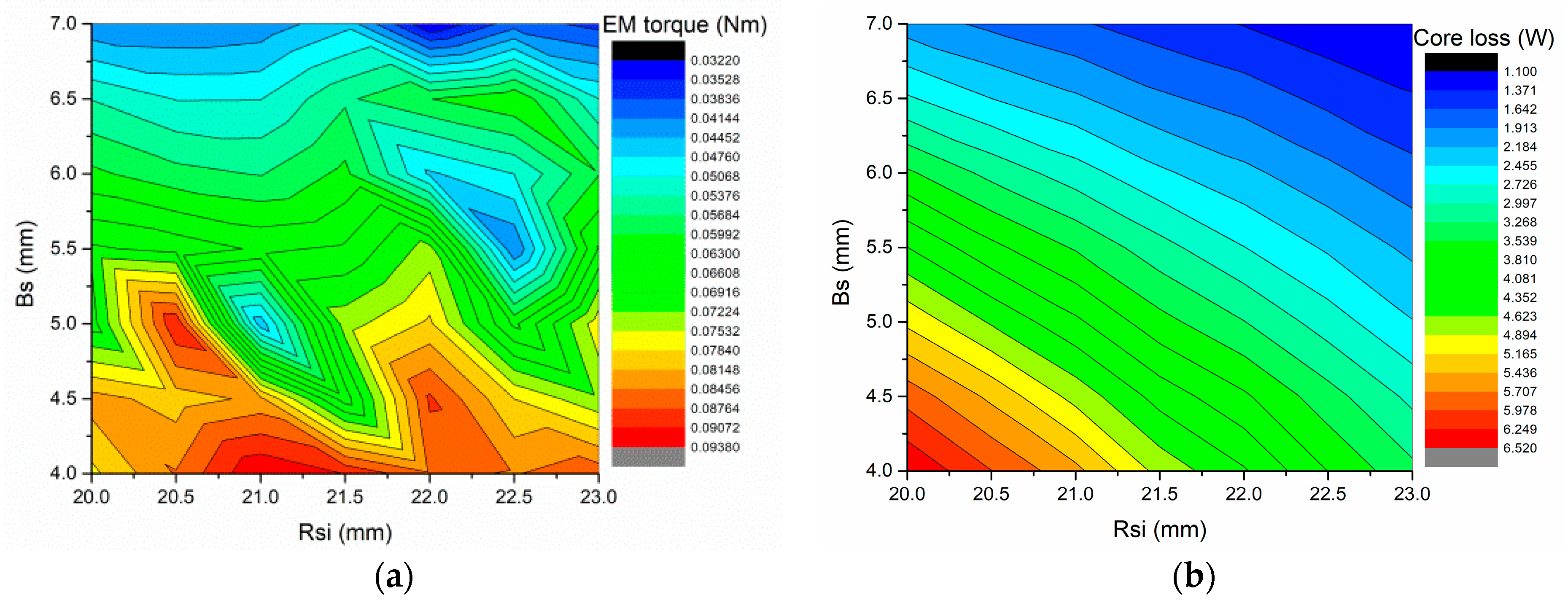
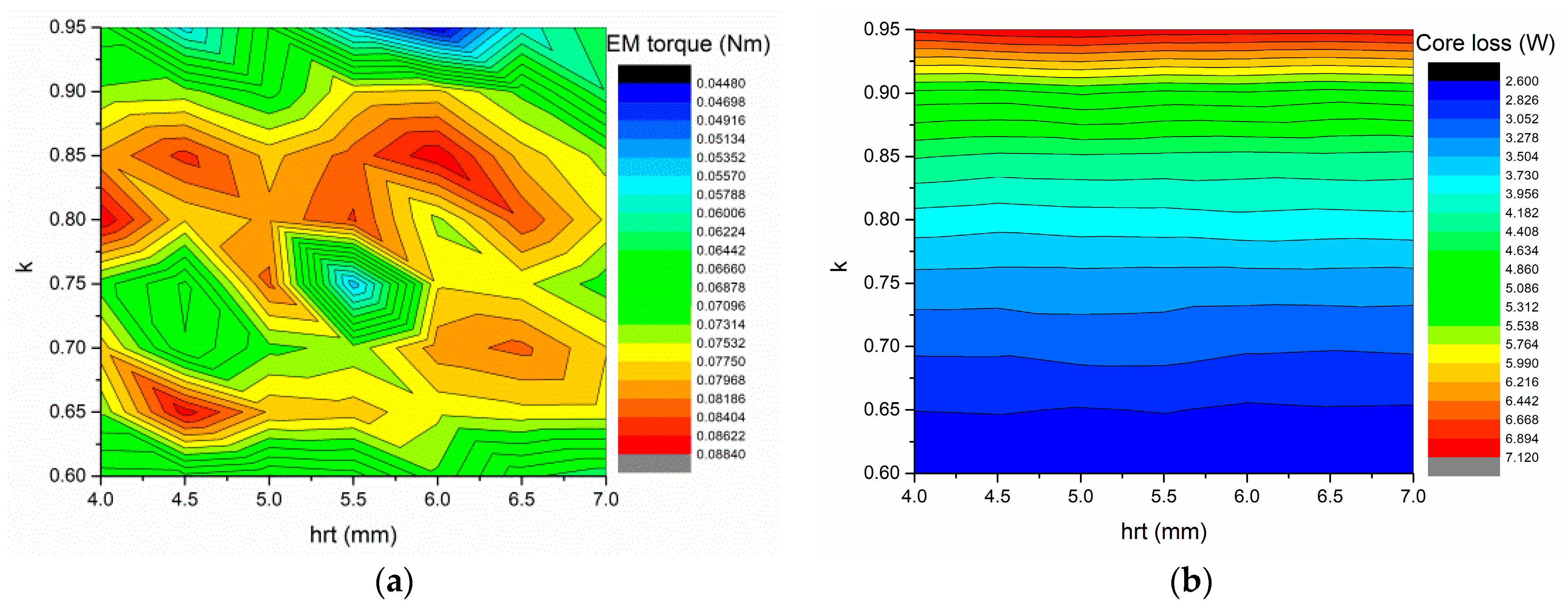
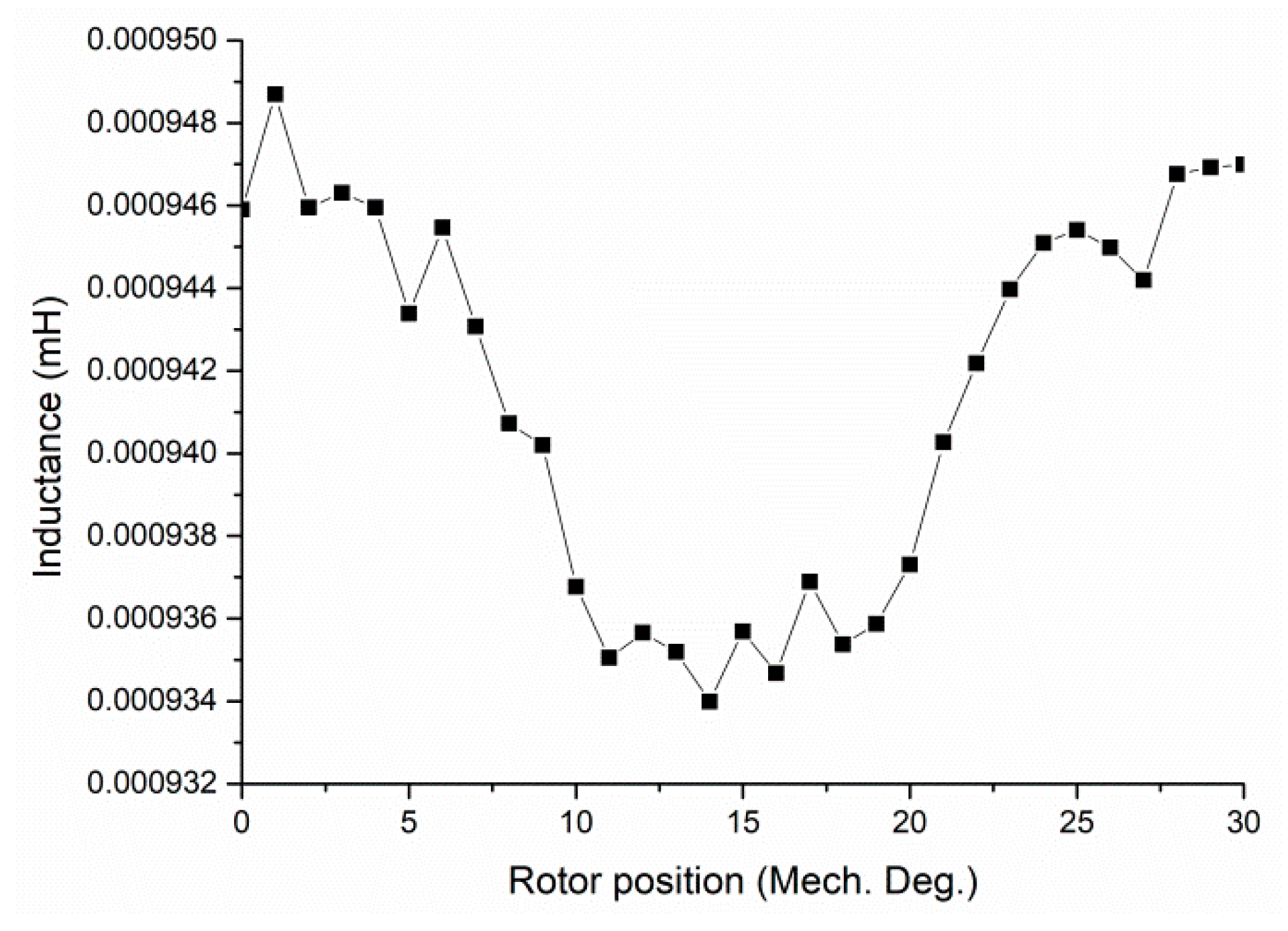
4. Parameters Analysis

Figure 4 shows the PM flux per turn of FRCPM using 3D FEM. It shows that the maximum value of the PM flux linkage per turn is 0.06 mWb, approximately within the period of 30 degrees. It can be used to verify the above theoretical analysis results.
Figure 5a shows the waveform of back EMF per winding calculated at a rotor speed of 1800 rpm, which is an approximate sine waveform. The analysis of harmonic contents, as shown in Figure 5b, exhibits that the fundamental content is dominant, but the high-order harmonics still exist.
The existence of leakage flux between the adjacent PMs located at stator claw pole teeth will lead to leakage inductance. Figure 6 shows the small variation of inductance on the rotor position with the average value of about 0.94 uH; for performance prediction, a d-axis current equaling zero is used.
The cogging torque resulting from the interaction between the PM on the stator, or rotor and the rotor slot or stator slot, causes the torque ripple, vibration, and noise. It also affects the starting process of a machine. The co-energy method is used to calculate the cogging torque. To reduce the time consumption, the variation of three-phase cogging torque on the rotor positions is obtained by combining three one-phase torques, as shown in Figure 7. The three-phase structure is arranged in the axial direction, and there is insulation between phases, which do not affect each other so that it can be calculated independently, and the results can be superimposed. It can be seen that the magnitude of three-phase cogging torque is about 0.2 Nm, while the magnitude of single-phase cogging torque is about 0.5 Nm. The main order for one-phase cogging torque has two periods, and the main order for three-phase cogging torque has six periods, which can be verified by using the harmonics order analysis method.

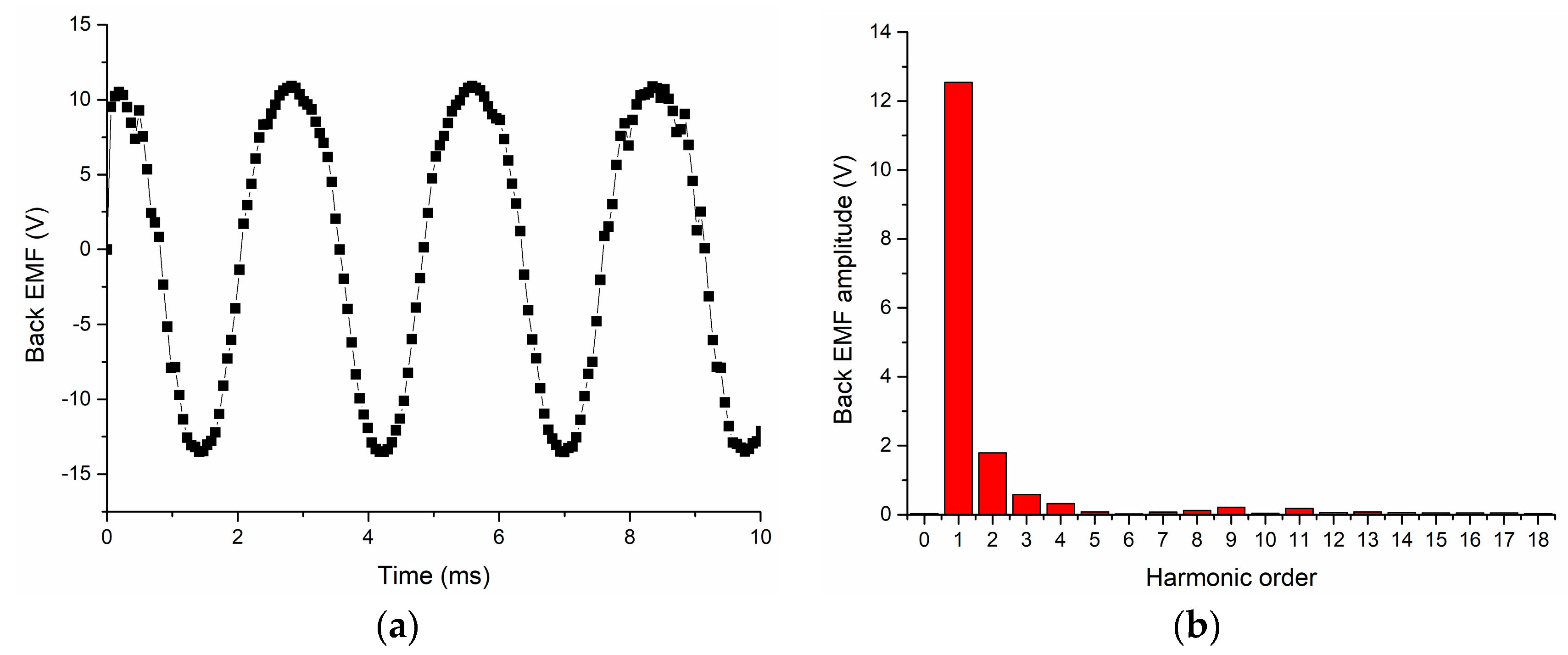
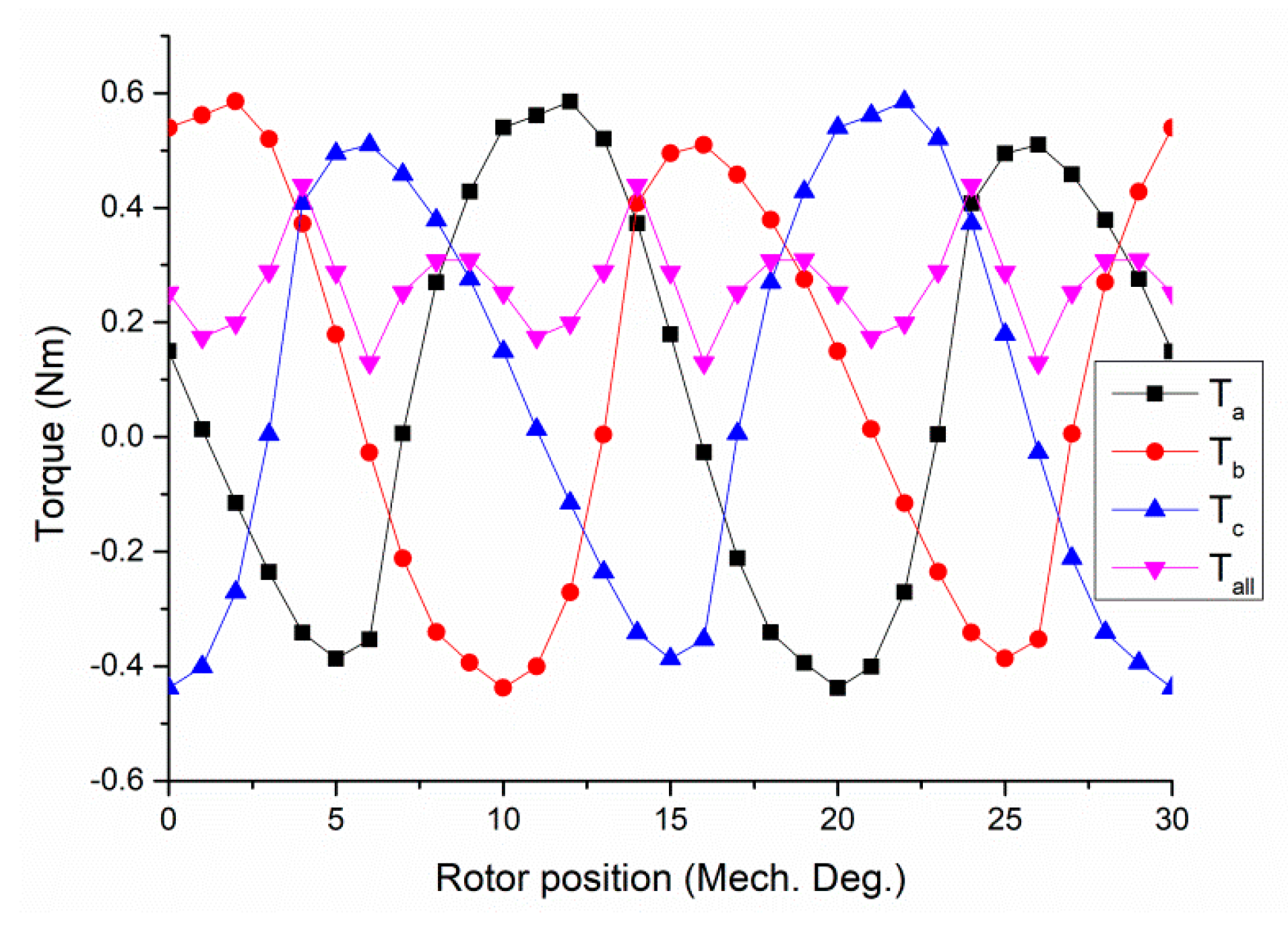
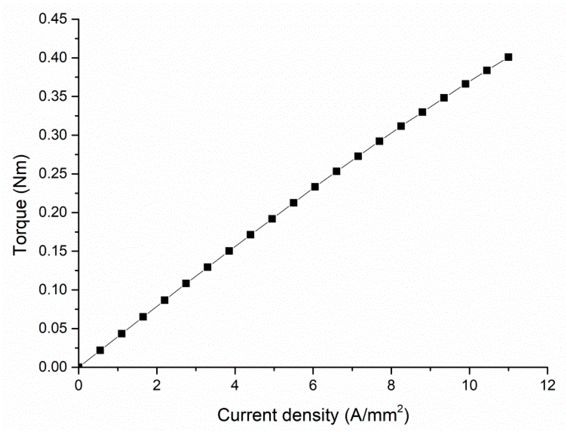
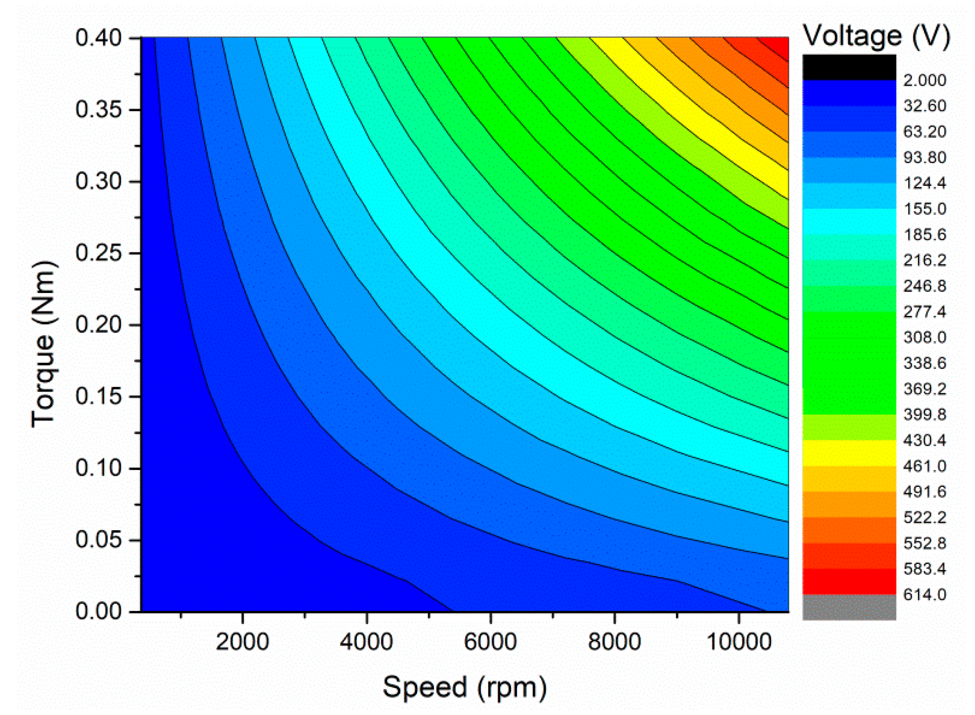
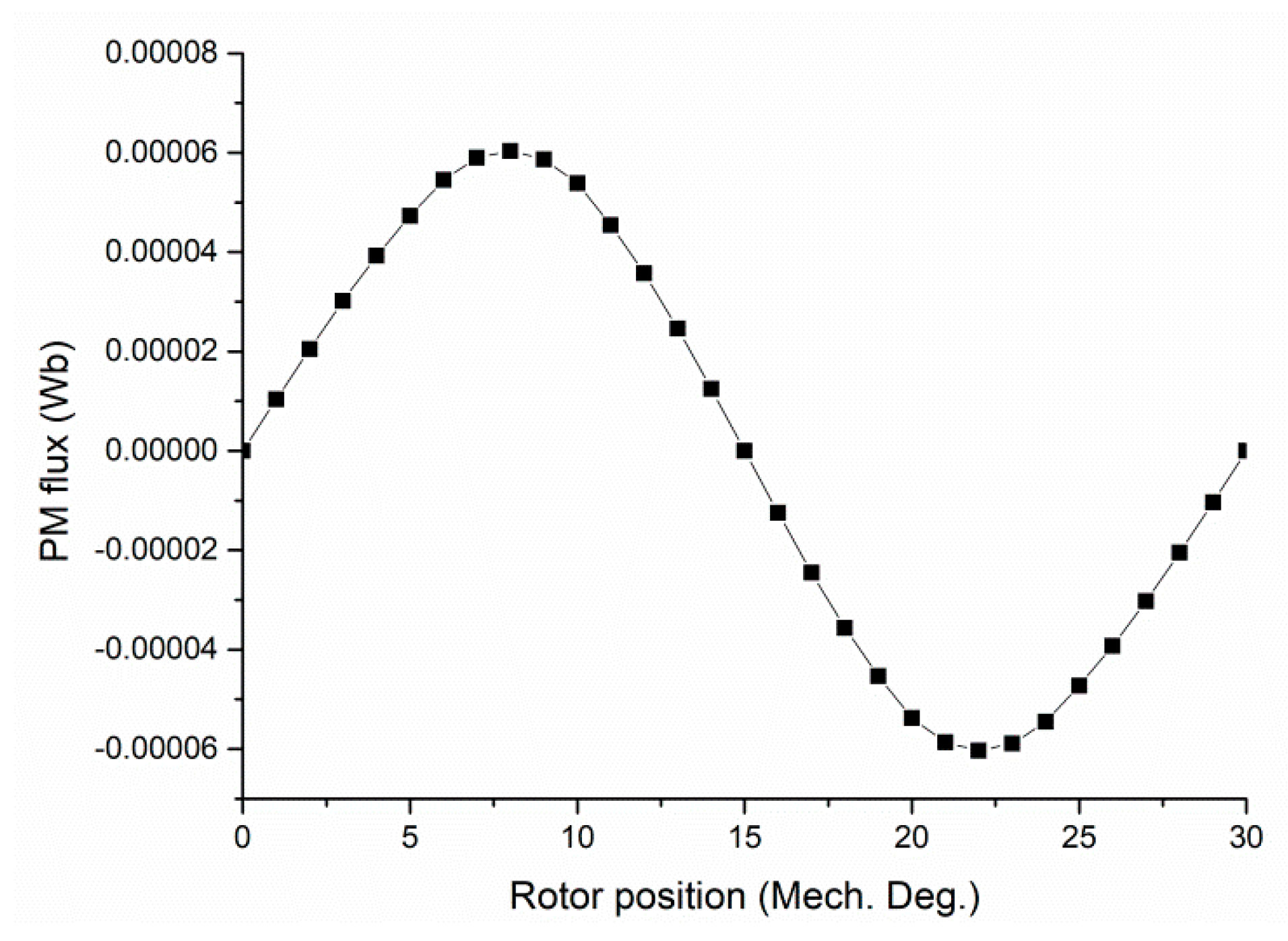
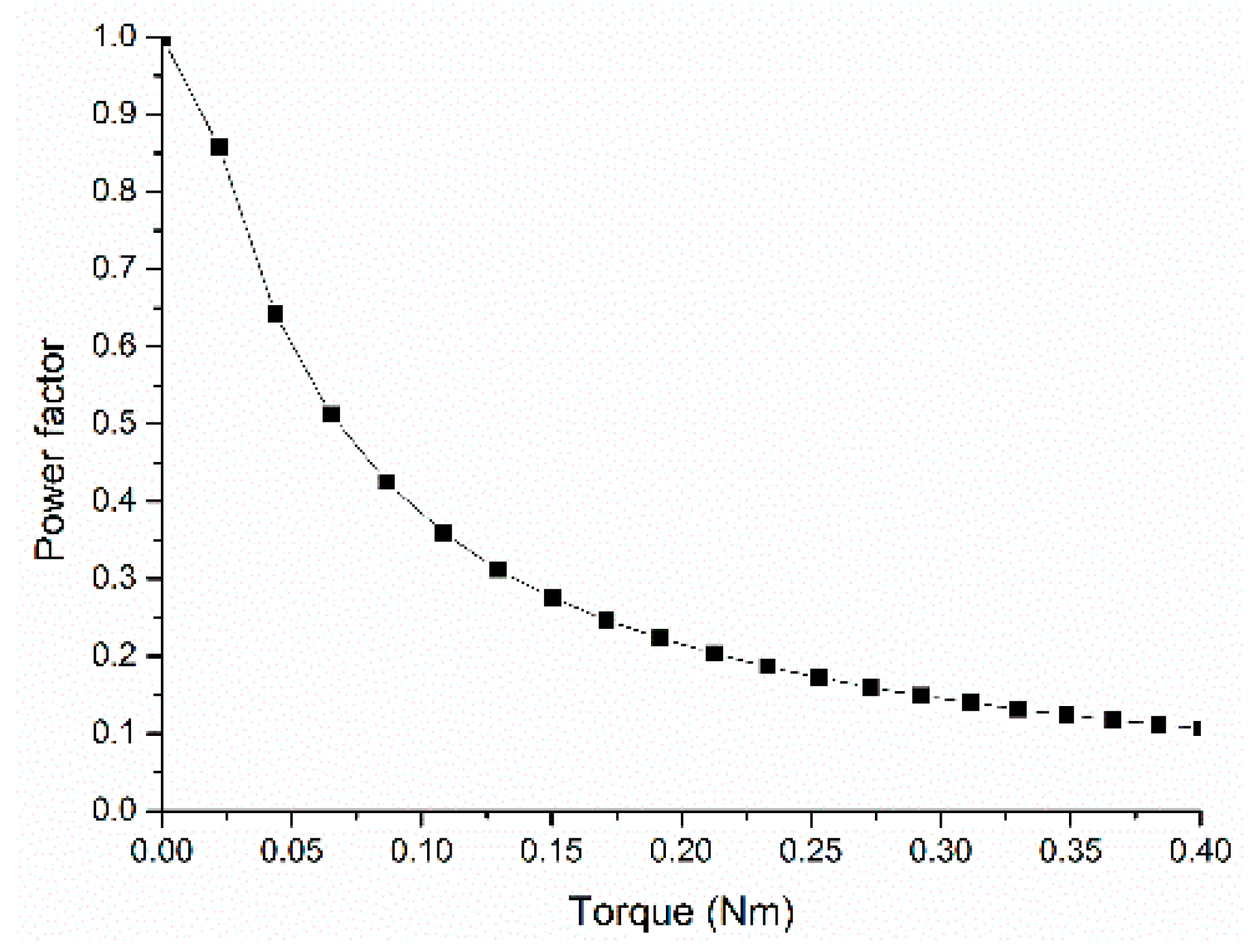
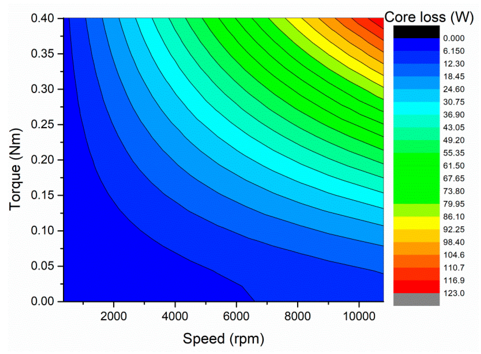
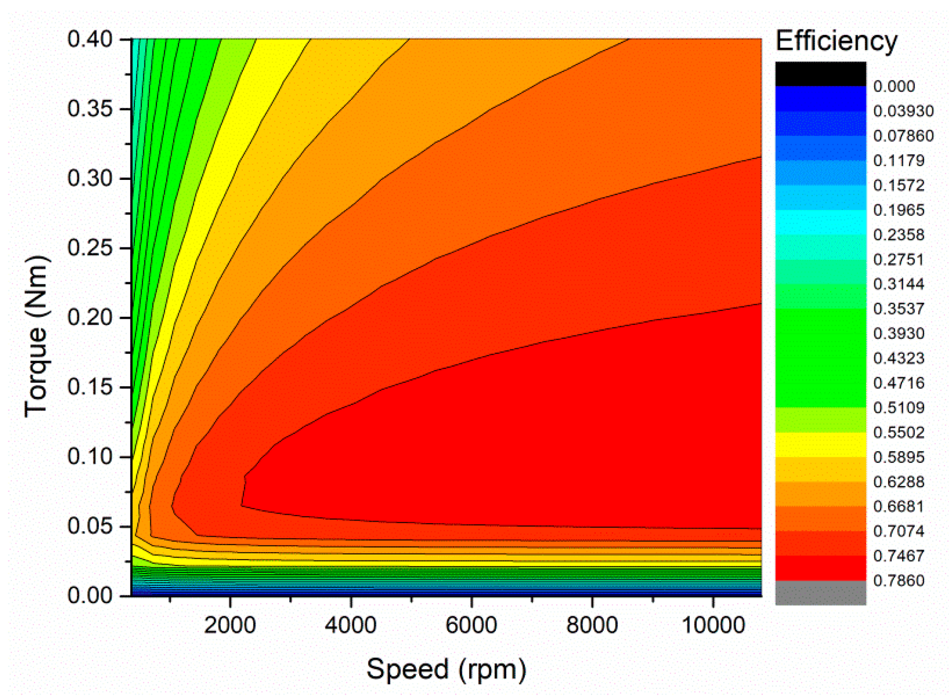
5. Performance Analysis

The torque and loss characteristics are important parameters to indicate the performance of FRCPM, and they are calculated in different excitation conditions. The performance is analyzed by setting the d-axis current to zero based on the assumption that the FRCMP only has PM torque without reluctance torque since the d-axis and q-axis inductance are very close. Figure 8 shows the waveform of EM torque at the rated state. The overall torque combines three torques obtained at different phases together. It can be seen that the average torque is about 0.25 Nm when the current density is 6 A/mm2. However, the peak to peak value is about 0.3 Nm, close to the average torque. The change of the average EM torque is linear to the applied current density, approximately up to the value of 11 A/mm2, as shown in Figure 9. Such a linear relationship indicates that higher torque could be achieved by increasing the current density.
For driving the FRCPM, an inverter is required, and the power factor is a very important parameter to characterize the machine performance. If the power factor is very low, it will lead to the inverter’s capacity being much higher than the power of the PM machine. The power factor of the PM machine is calculated by
P f a c t o r = 1 1 + ( ω c L s I s / E 0 ) 2
where ωc is the electrical angular speed, Ls is the synchronous inductance, Is is the input current, and E0 is the back EMF. Figure 10 shows the power factors at the different torques at 1800 rpm. The power factor decreases quickly when increasing the torque, particularly in the range of lower torque. The power factor is about 0.2 at the rated torque of 0.25 Nm. Fortunately, the region of the constant power speed is wider while the power factor is lower.
The core loss indicates that the power efficiency has to be analyzed since the FRCPM studied in this paper will operate at a high frequency. However, the mechanism of rotational core loss is not clearly understood, and experimental data are insufficient in spite of a great amount of attention paid to the rotational core loss. Instead, the coefficient of alternating core loss obtained from the calculated core loss loops of the stator claw pole is adopted to calculate the core loss. Figure 11 illustrates the core losses at different torques and speeds. The calculations show that the core loss will increase with an increasing torque or speed. The speed has to be decreased in the case of an increase in torque to keep the same core loss or vice versa.
The operation state of FRCPM is determined by many factors. The maximum torque depends on the applied maximum winding current below the rated speed. In addition, the maximum torque at the speed from the rated speed to maximum speed depends on the applied maximum voltage. Temperature rise and mechanical characteristics are the other two constraints. In this FRCPM, there is no wind or liquid cooling applied; consequently, the maximum current density of FRCPM is limited to 10 A/mm2, and the rated current density is 6 A/mm2. Figure 12 shows the voltage constraints of FRCPM on different speeds and torque. It can be seen that with the increase in voltage, the FRCPM can be operated in more regions and achieve higher power.
The efficiency of the designed FRCPM at different operating states is mapped in Figure 13. It is calculated by the equation
η = P e m P c o r e P e m + P c o p p e r
where Pem is the electromagnetic power, Pcore is the core loss, and Pcopper is the copper loss. For the same efficiency, the higher the speed, the larger the torque range. For example, for the maximum efficiency of 0.78, the torque range is between 0.05 Nm and 0.3 Nm if the speed is set at 1000 rpm.

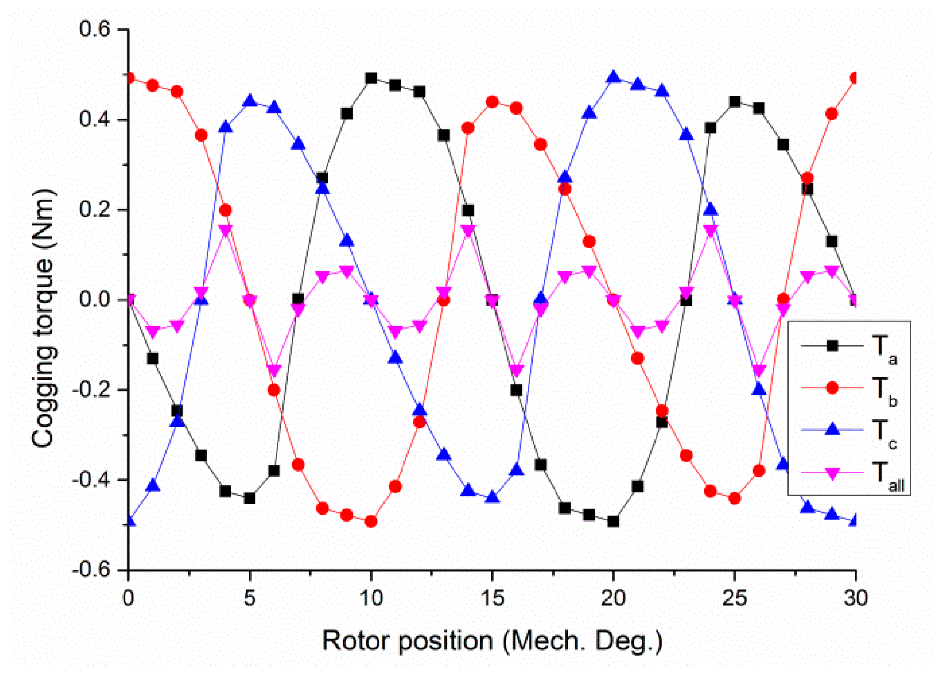
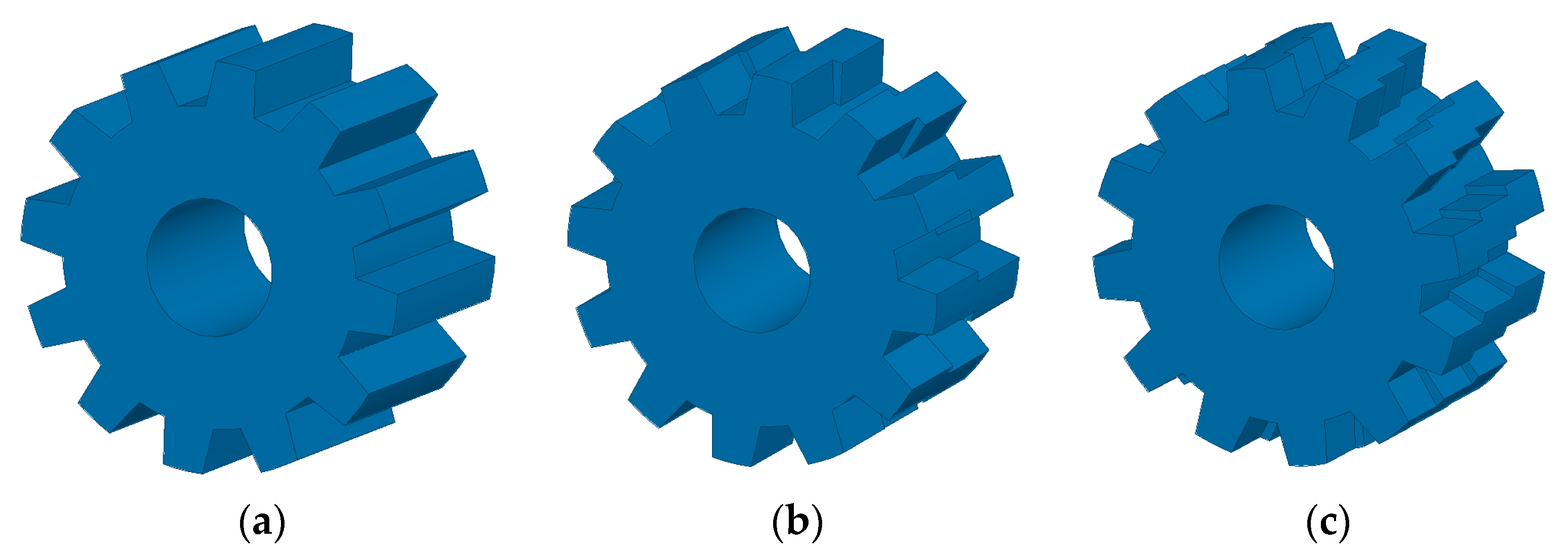
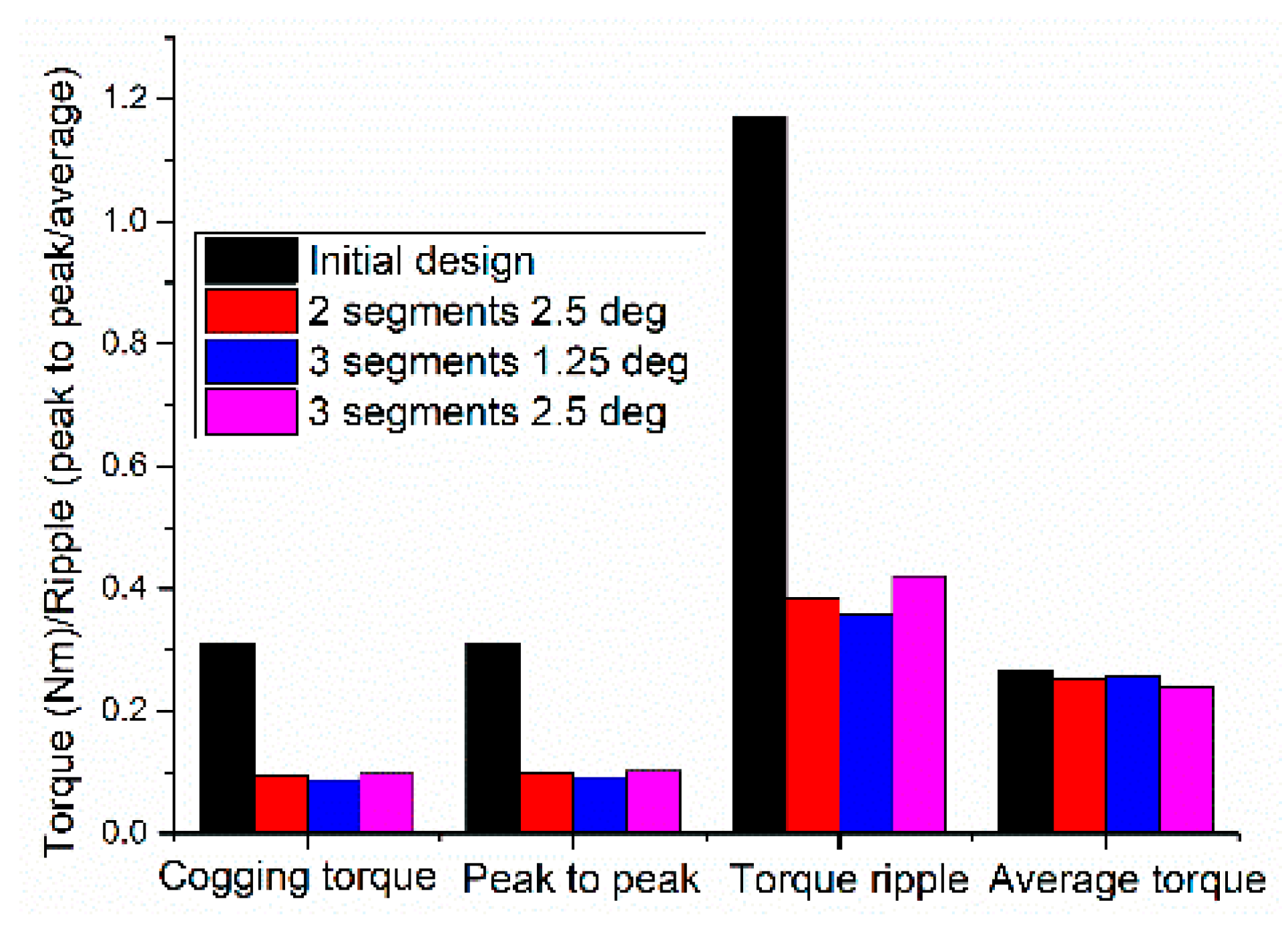
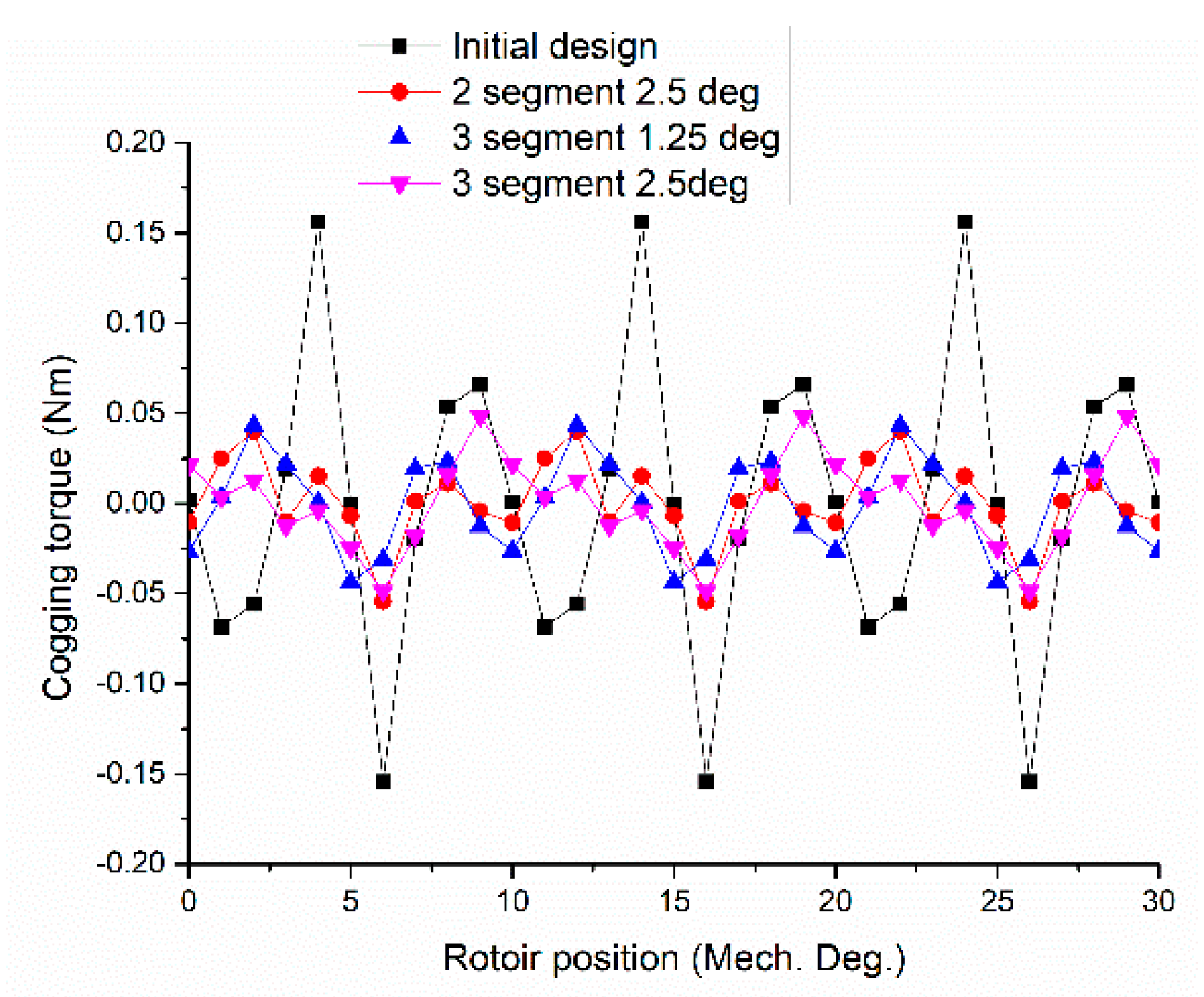
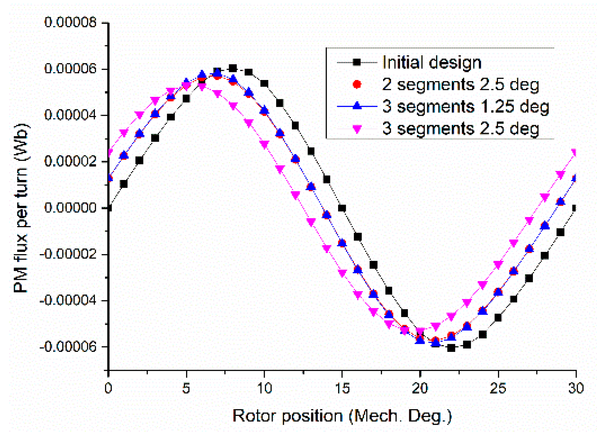
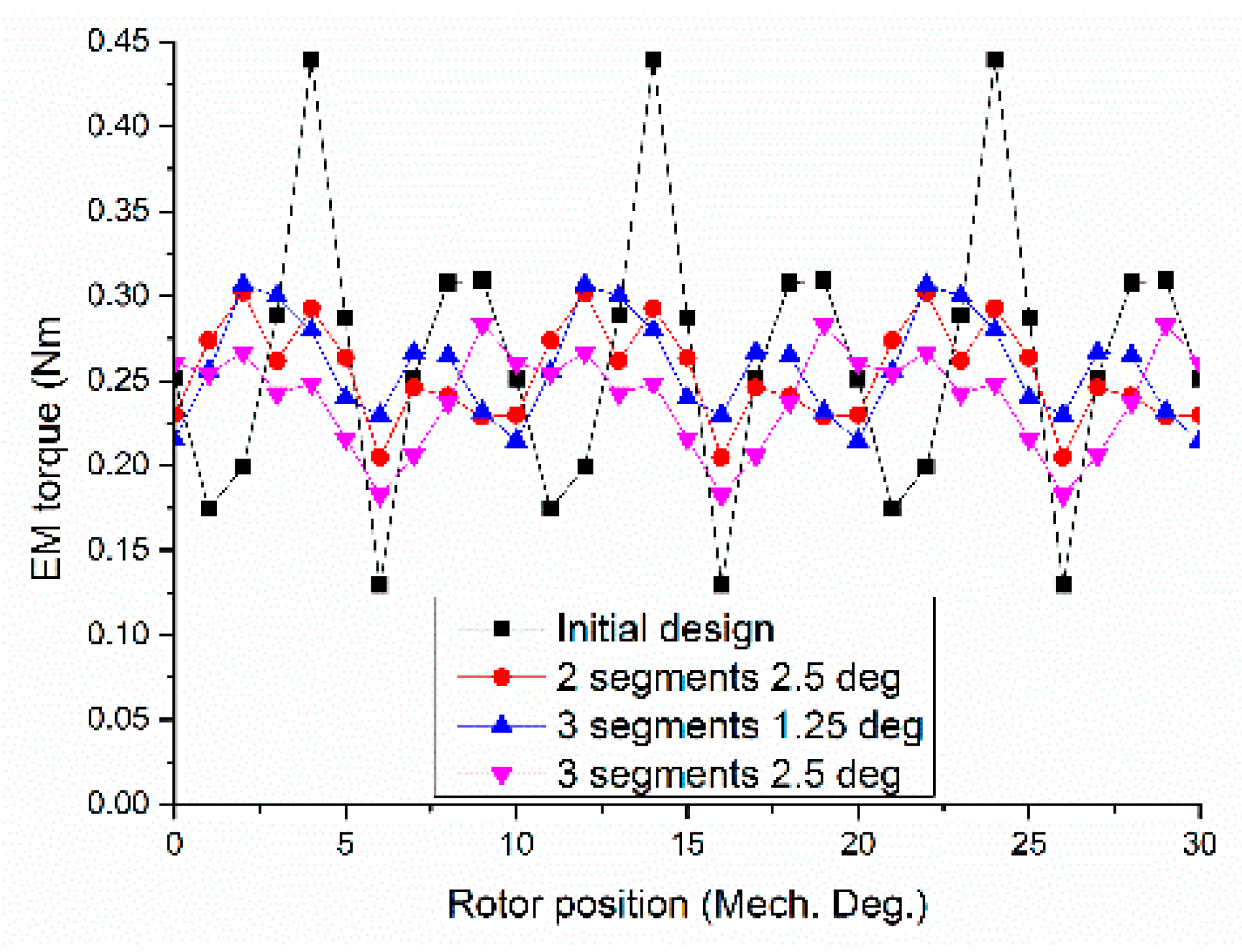
6. Cogging Torque Minimization

The cogging torque causes speed ripples and induces the vibrations of the machine. There are many methods developed to reduce the cogging torque, including the combination of the number of stator slots and rotor poles, rotor pole pairing, rotor pole skewing, etc. [22,23,24]. As a special kind of transverse flux machine, the designed FRCPM is different from the traditional PM machine, and the number of stator slots equals the rotor poles. Thus, the cogging torque can be reduced by increasing the number of rotor poles. However, an increase in rotor poles will lead to a reduction in the average electromagnetic force or torque and power factor. This paper adopts the method of rotor pole skewing to reduce the cogging torque.
For a skewed rotor, the resultant cogging torque of FRCPM can be calculated using
T c o g ( θ m ) = n = 1 T n 2 [ sin ( n N c θ m + φ k ) + sin ( n N c ( θ m + θ s ) + φ n ) ] = n = 1 T n cos ( n N c θ s 2 ) × sin [ n N c ( θ m + θ s 2 ) + φ n ]
where θm is the rotor rotating angle, Tn is the amplitude of the n-th harmonic component of the cogging torque, φk is the phase angle of the n-th harmonic component of the cogging torque, and Nc is the least common multiple between the number of stator slots and the number of rotor poles. In the FRCPM, Nc equals the number of rotor poles. The amplitude of the cogging torque of CPM can be calculated by the FEM. For the CPM analyzed in this paper, when n is a multiple of six, the Tn appears, and when k increases, Tn decreases, where θs is the skew angle. The n-th cogging torque Tn can be decreased by an alleviating factor
cos ( n N c θ s 2 )
For FRCPM, the ideal skewing angle is about 2.5 degrees mechanically. However, for the developed FRCPM, the cogging torque of the 12th harmonic order is high as well, and the effective skewing angle will be slightly different from the calculated skewing angle.
Figure 14 illustrates the rotor structures analyzed in the paper, for example, the initial rotor design for FRCPM: a rotor with two segments skewed by 2.5 degrees and a rotor with three segments skewed by 2.5 degrees. The calculations of their cogging torques use the same method as the last section. The results show that the cogging torque for both two segments skewed by 2.5 degrees and three segments skewed by 2.5 degrees and 1.25 degrees have similar values, which is much lower than the initial design, as illustrated in Figure 15.
It is well known that a reduction in cogging torque will lead to the degradation of the electromagnetic performance of FRCPM, so the main electromagnetic performance of FRCPM using a skewing rotor needs to be re-calculated. As shown in Figure 16, the PM flux per turn of FRCPM for two segments, 2.5 degrees skewed, and three segments, 1.25 degrees skewed, are the same, which are lower than that of initial FRCPM, while the PM flux per turn for FRCPM using three segments demonstrated that 2.5 degrees skewed is the lowest one. For this reason, the rotor structure of three segments, 2.5 degrees skewed, is not considered further in the paper. Figure 17 shows the comparison of torque of FRCPM with three different designs. The rated torque of the motor is 0.2 Nm. It can be seen that the torque ripple has been reduced greatly with the rotor pole skewed with determined angles; however, the average torque is reduced slightly as well. Moreover, compared with the FRCPM with two segments skewed by 2.5 degrees, the torque ripple for FRCPM with three segments skewed 1.25 degrees is much lower despite the average torque being the same. From the point of view of the manufacturing cost, few rotor cores stacked together with a skewed angle will cost more compared with the one rotor core having few teeth. In the overall comparison of cogging torque, peak-to-peak value of cogging torque, the amplitude of torque ripple, and average torque, Figure 18 reveals that rotor skewing is an effective way to reduce the cogging torque and torque ripple of FRCPM, and the skewing structure of rotor has a little impact on the average torque. In addition, the torque ripple for FRCPM results from the cogging torque. Among the three-rotor skewing structures, the skewing rotor with three segments of 1.25 degrees has the best performance. Alternatively, the rotor with two segments skewed by 2.5 degrees would also be an ideal structure for the manufacturing reason due to the complexity of three segments.

7. Conclusions

A novel FRCMP that combines the merits of CPM and FRPMM is analyzed in this paper. Briefly, 3D magnetic flux and global wing windings result in high torque efficiencies. There were no windings and magnets on the rotor cores leading to high-speed operation. Based on the FEM analysis, the rotor structure was optimized to obtain better performance. The analysis reveals that the proposed FRCPM can achieve high torque and efficiency compared with traditional claw poles with magnets on rotors. In addition, the comparison of four-rotor structures shows that the skewing rotor pole technique is an effective method in minimizing cogging torque and torque ripple of the FRCPM. The developed FRCPM can overcome the low mechanical robustness of the SMC machine since both magnets and SMC cores can be encapsulated as one part.

Author Contributions

Data curation, B.L.; Formal analysis, X.L. and Y.W.; Software, S.W. and R.L.; Writing—review & editing, Z.L. All authors have read and agreed to the published version of the manuscript.

Funding

This research was funded by the Natural Science Foundation of Hebei Province under Grant E2019202220 and the Chinese National Science Foundation under grant 52007047.

Data Availability Statement

Not applicable.

Conflicts of Interest

The authors declare no conflict of interest.

References

  1. Deodhar, R.; Andersson, S.; Boldea, I.; Miller, T. The flux-reversal machine: A new brushless doubly-salient permanent-magnet machine. IEEE Trans. Ind. Appl. 1997, 33, 925–934. [Google Scholar] [CrossRef]
  2. More, D.S.; Kalluru, H.; Fernandes, B.G. Outer rotor flux reversal machine for rooftop wind generator. In Proceedings of the 2008 IEEE Industry Applications Society Annual Meeting, Edmonton, AB, Canada, 5–9 October 2008; pp. 1–6. [Google Scholar]
  3. Wang, C.X.; Boldea, I.; Nasar, S.A. Characterization of three phase flux reversal machine as an automotive generator. IEEE Trans. Energy Convers. 2001, 16, 74–80. [Google Scholar] [CrossRef]
  4. Qu, H.; Zhu, Z.Q.; Li, H. Analysis of Novel Consequent Pole Flux Reversal Permanent Magnet Machines. IEEE Trans. Ind. Appl. 2021, 57, 382–396. [Google Scholar] [CrossRef]
  5. More, D.; Fernandes, B. Analysis of flux-reversal machine based on fictitious electrical gear. IEEE Trans. Energy Convers. 2010, 25, 940–947. [Google Scholar] [CrossRef]
  6. Boldea, I.; Zhang, L.; Nasar, S.A. Theoretical characterization of flux reversal machine in low-speed servo drives—The pole-PM configuration. IEEE Trans. Ind. Appl. 2002, 38, 1549–1557. [Google Scholar] [CrossRef]
  7. Gao, Y.; Qu, R.; Li, D.; Li, J.; Wu, L. Design of three-phase flux reversal machines with fractional-slot windings. IEEE Trans. Ind. Appl. 2016, 52, 2856–2864. [Google Scholar] [CrossRef]
  8. More, D.; Fernandes, B. Power density improvement of three phase flux reversal machine with distributed winding. IET J. Elect. Power Appl. 2010, 4, 109–120. [Google Scholar] [CrossRef]
  9. Kim, T.; Won, S.; Bong, K.; Lee, J. Reduction in cogging torque in flux reversal machine by rotor teeth pairing. IEEE Trans. Magn. 2005, 41, 3964–3966. [Google Scholar]
  10. Gao, Y.; Qu, R.; Li, D.; Li, J. Torque performance analysis of three phase flux reversal machines for electric vehicle propulsion. IEEE Trans. Ind. Appl. 2017, 53, 2110–2119. [Google Scholar] [CrossRef]
  11. Zhu, X.; Hua, W.; Wu, Z. Cogging torque suppression in flux reversal permanent magnet machines. IET Electr. Power Appl. 2017, 12, 135–143. [Google Scholar] [CrossRef]
  12. Liu, C.; Lei, G.; Wang, T.; Guo, Y.; Wang, Y.; Zhu, J. Comparative study of small electrical machines with soft magnetic composite cores. IEEE Trans. Ind. Electron. 2017, 64, 1049–1060. [Google Scholar] [CrossRef]
  13. Liu, C.; Zhu, J.; Wang, Y.; Lei, G.; Guo, Y. Design considerations of PM transverse flux machine with SMC cores. IEEE Trans. Appl. Supercond. 2016, 26, 5203505. [Google Scholar]
  14. Liu, C.C.; Wang, D.Y.; Wang, S.P.; Wang, Y.H. A Novel Flux Reversal Claw Pole Machine with Soft Magnetic Composite Cores. IEEE Trans. Appl. Supercond. 2020, 30, 5202905. [Google Scholar] [CrossRef]
  15. Guo, Y.; Zhu, J.; Watterson, P.; Wu, W. Development of a PM transverse flux motor with soft magnetic composite core. IEEE Trans. Energy Convers. 2006, 21, 426–434. [Google Scholar] [CrossRef]
  16. Jack, A.G.; Mecrow, B.C.; Maddison, C.P.; Wahab, N.A. Claw pole armature permanent magnet machines exploiting soft iron powder metallurgy. In Proceedings of the IEEE International Electric Machines and Drives Conference Record, Milwaukee, WI, USA, 18–21 May 1997. [Google Scholar]
  17. Guo, Y.G.; Zhu, J.G.; Dorrell, D.G. Design and analysis of a claw pole permanent magnet motor with molded soft magnetic composite core. IEEE Trans. Magn. 2009, 45, 4582–4585. [Google Scholar]
  18. Lei, G.; Wang, T.S.; Guo, Y.G.; Zhu, J.G.; Wang, S.H. System level design optimization methods for electrical drive systems: Deterministic approach. IEEE Trans. Ind. Electron. 2014, 61, 6591–6602. [Google Scholar] [CrossRef]
  19. Lei, G.; Wang, T.S.; Zhu, J.G.; Guo, Y.G.; Wang, S.H. System level design optimization methods for electrical drive systems: Robust approach. IEEE Trans. Ind. Electron. 2015, 62, 4702–4713. [Google Scholar] [CrossRef]
  20. Ryu, J.; Hahn, I. Axially Stacked Multiphase Flux Reversal Machine. In Proceedings of the IECON 2019—45th Annual Conference of the IEEE Industrial Electronics Society, Lisbon, Portugal, 14–17 October 2019. [Google Scholar]
  21. Liu, C.; Wang, D.; Wang, S.; Niu, F.; Wang, Y.; Lei, G.; Zhu, J. Design and Analysis of a New Permanent Magnet Claw Pole Machine with S-Shape Winding. IEEE Trans. Magn. 2021, 57, 8103605. [Google Scholar] [CrossRef]
  22. Fang, H.; Li, D.; Qu, R.; Li, J.; Liang, D. Vibration Suppression for Flux-Switching PM Machines. IEEE Trans. Energy Convers. 2018, 33, 959–969. [Google Scholar] [CrossRef]
  23. Hao, W.; Wang, Y. Comparison of the Stator Step Skewed Structures for Cogging Force Reduction of Linear Flux Switching Permanent Magnet Machines. Energies 2018, 11, 2172. [Google Scholar] [CrossRef] [Green Version]
  24. Hao, L.; Lin, M.; Xu, D.; Li, N.; Zhang, W. Analysis of Cogging Torque Reduction Techniques in Axial-Field Flux-Switching Permanent-Magnet Machine. IEEE Trans. Appl. Supercond. 2016, 26, 5200605. [Google Scholar] [CrossRef]
Figure 1. (a) Main topology of FRCPM; (b) Main dimension of FRCPM.
Energies 15 01285 g001
Figure 2. Optimization of the thickness of the stator wall and inner radius of the stator core: (a) EM torque; (b) Core loss.
Energies 15 01285 g002
Figure 3. Optimization of the ratio of stator claw pole to the height of rotor teeth: (a) EM torque; (b) Core loss.
Energies 15 01285 g003
Figure 4. PM flux per turn of FRCPM.
Energies 15 01285 g004
Figure 5. Back EMF of FRCPM at speed of 1800 rpm: (a) Back EMF per winding; (b) Harmonic contents and amplitude of back EMF.
Energies 15 01285 g005
Figure 6. Inductance per turn of FRCPM.
Energies 15 01285 g006
Figure 7. Cogging torque of FRCPM.
Energies 15 01285 g007
Figure 8. EM torque of FRCPM.
Energies 15 01285 g008
Figure 9. EM torque with the variation of current density.
Energies 15 01285 g009
Figure 10. Power factor of FRCPM.
Energies 15 01285 g010
Figure 11. Core loss with the variation of torque and speed.
Energies 15 01285 g011
Figure 12. DC voltage of FRCPM with the variation of torque and speed.
Energies 15 01285 g012
Figure 13. Efficiency map.
Energies 15 01285 g013
Figure 14. Rotor for FRCPM with different configurations: (a) initial design; (b) 2 segments with 2.5 degrees shift; (c) 3 segments with 2.5 degrees shift.
Energies 15 01285 g014
Figure 15. Resulting cogging torque with different machine designs.
Energies 15 01285 g015
Figure 16. PM flux per turn with different machine designs.
Energies 15 01285 g016
Figure 17. EM torque with three different machine designs.
Energies 15 01285 g017
Figure 18. The overall conclusion of three different machine designs.
Energies 15 01285 g018
Table 1. Comparison of three kinds of motors.
TypeFRPMMCPMFRCPM
Stucture Energies 15 01285 i001 Energies 15 01285 i002 Energies 15 01285 i003
CharacterHigh fault tolerance and mechanical robustness.High torque and power factor.High torque and speed operation.
Table 2. Main parameters of proposed FRCPM.
ParameterSymbolValueUnit
Stator outer radiusRso33.5mm
Stator inner radiusRsi22.5mm
Axial length per stackL118.2mm
Thickness of stator wallBs4mm
Thickness of stator claw poleHp3mm
Thickness of stator yokeHsy3mm
Angle of stator claw poleAnglecp24deg
Thickness of PMhrm3mm
Air gap lengthg10.5mm
Rotor outer radiusRro19mm
Angle of rotor teethAnglert12deg
Length of rotor teethhrt4mm
Rotor inner radiusRri6mm
Number of winding turnsNcoil100
Stator core materialSMOLAY 500 TM
PM materialBr = 1.15 T, ur = 1.05
Publisher’s Note: MDPI stays neutral with regard to jurisdictional claims in published maps and institutional affiliations.

