1. Introduction
A wheel loader is a kind of earth and stone construction machine widely used in highways, buildings, mines, and other construction projects. Different auxiliary work equipment can be used for different loading and unloading operations [
1,
2,
3]. Because the loader steers frequently when loaded and unloaded, there are high requirements for the stability and safety of the steering system. At present, the loaders on the market have the problem of loader steering vibration, which affects the driver’s operation of the machine [
4,
5,
6]. Therefore, it is very necessary to optimize the steering system of the loader.
At present, there are many studies on the full hydraulic steering system [
7,
8,
9,
10]. Bing-wei Cao studied the influence of the position of the hinge point of the steering cylinder of the wheel loader on the pressure fluctuation of the steering system, and optimized the position of the hinge point to reduce the pressure fluctuation [
11]. Barbara Zardin proposed a lumped parameter model to simulate steering behavior, and optimized the system through a parameter sensitivity analysis [
12]. Many researchers have reduced pressure fluctuations by adding pressure relief holes in the hydraulic steering system, but they have not fundamentally solved the problem [
13,
14]. Taotao Jin designed a PID controller based on genetic algorithm which controls the electro-hydraulic proportional valve and hydraulic oil flow through pressure fluctuations, which can restrain the pressure fluctuations during the steering process of tracked vehicles well [
15]. Dell’Amico simulated the electro-hydraulic power steering system and found that the high response of the pressure control loop is ideal for a good steering feel, but instability may occur at higher steering wheel torque levels [
16]. Based on the theory of fractional calculus, Xu Feixiang and Liu Xinhui designed a fractional proportional integral derivative controller to control the movement of the steering cylinder in the SBW system. The optimized controller has a better transient response, tracking performance, and robustness than the traditional PID controller [
17]. Kwangseok Oh, Salem Haggag, Mattia Rigotti-Thompson and others improved steering performance and reduced energy consumption by adding control algorithms to hydraulic steering systems [
18,
19,
20,
21,
22]. The theories put forward by the above-mentioned researchers provide theoretical support for the optimization of hydraulic steering systems. These methods suppress pressure fluctuations by changing the system structure or adding control algorithms, but these methods are difficult to apply to wheel loaders.
This article focuses on the vibration problem of the wheel loader during the steering process. In this paper, a key point pressure test was carried out on the original prototype of the hydraulic steering system, the test data were processed and analyzed, and the prototype steering system was modeled and analyzed by AMESim to determine the causes of the steering stop vibration. The system was optimized by designing the cushion valve, and simulation and loading tests were performed on the cushion valve. Using a combination of theoretical analysis, simulation, and experiment, the impact of the cushion valve on the performance of the hydraulic steering system was analyzed. Results showed that that the analysis provides a reliable theoretical and experimental basis for the optimization of the hydraulic steering system and new ideas for the design of vehicle steering system.
2. Working Principle of Hydraulic Steering System
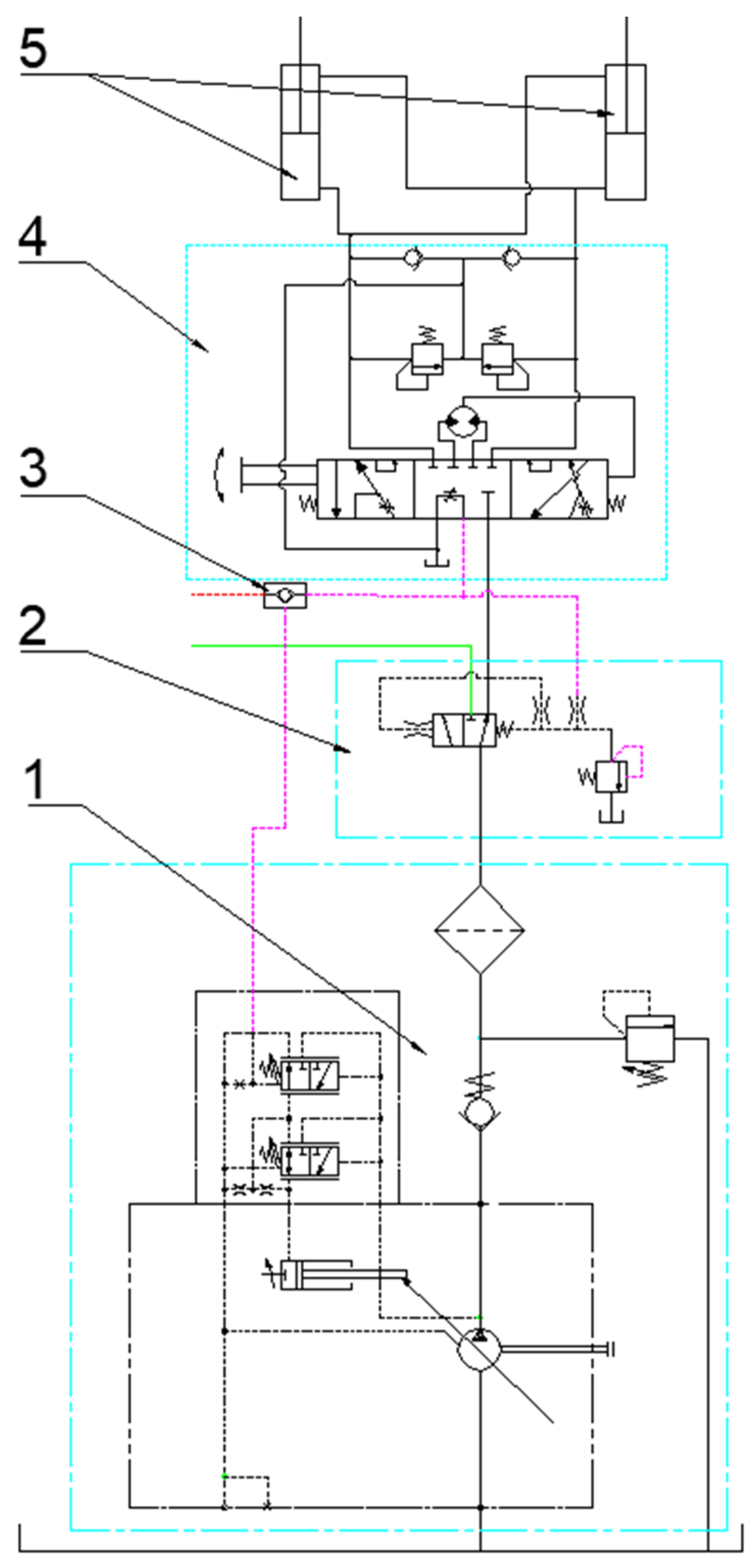
The research object of this paper is a 5-ton wheel loader. The hydraulic steering system of the loader is shown in
Figure 1.
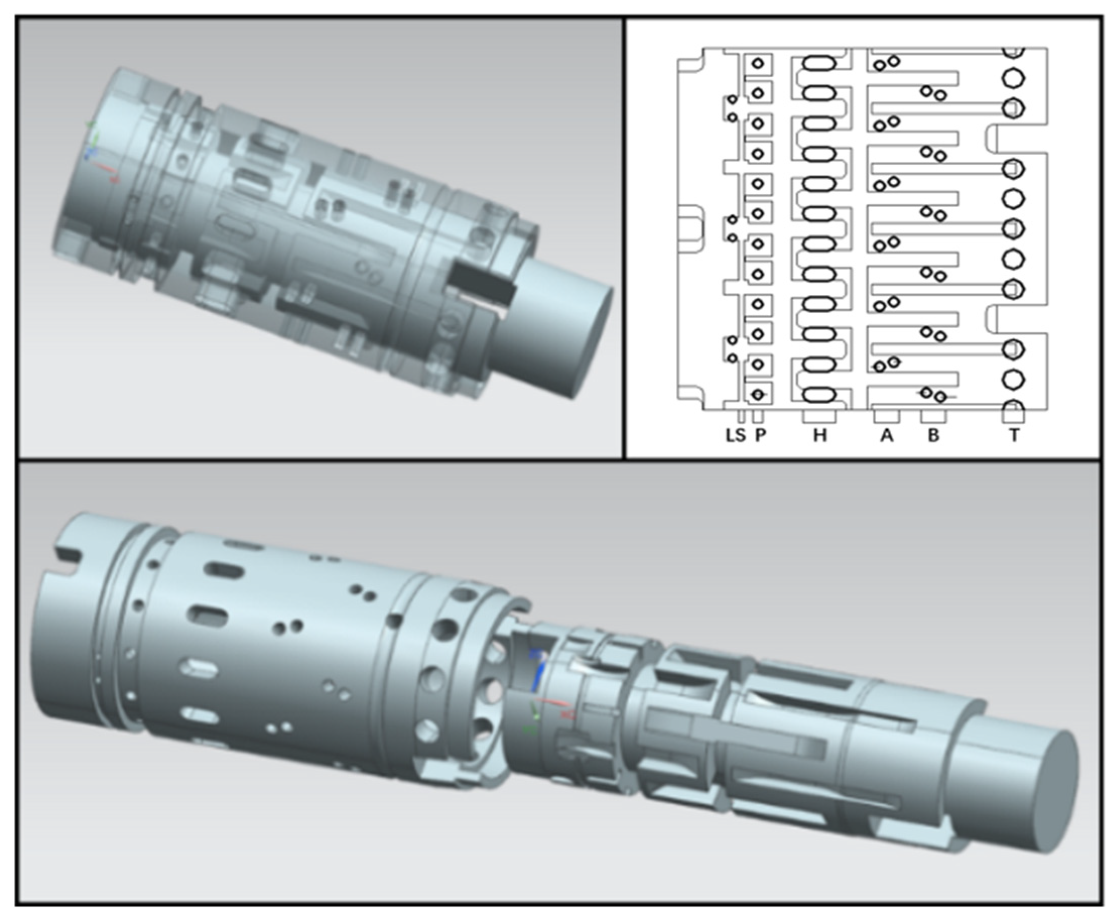
The hydrostatic steering unit body has 5 ports to communicate with the outside, P port, A port, B port, T port and LS port. The five annular grooves connect the hole of the valve sleeve with the outside, and the seven radial holes on the valve body connect the P port, A (B) port and the metering motor. The relationship between the hole and groove on the valve core and valve sleeve is shown in
Figure 2. The thick solid line in the expanded view is the orifice on the valve sleeve, and the thin solid line is the groove of the valve core. The relative sliding of the expanded view is the relative rotation of the valve core and the valve sleeve.
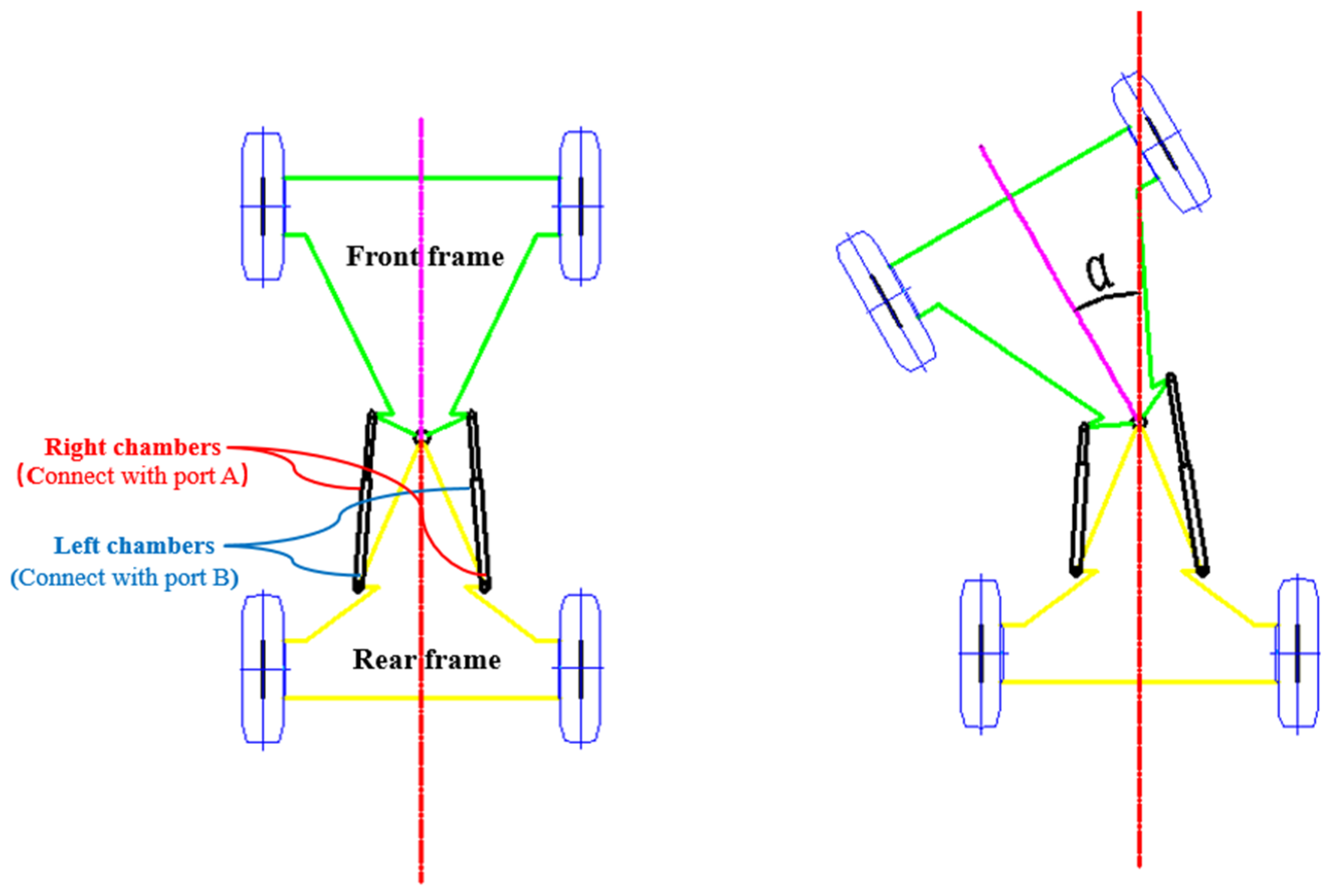
As shown in
Figure 3, the A port of the hydraulic steering unit is connected with the right chamber, and the B port of the hydraulic steering unit is connected with the left chamber. When the driver turns the steering wheel counterclockwise, the hydraulic steering unit A port provides oil and B port returns oil, the right steering cylinder extends, the left steering cylinder retracts. Then, the loader performs counterclockwise steering. On the contrary, the loader performs a clockwise steering action. The angle α between the front frame and the rear frame is the steering angle.
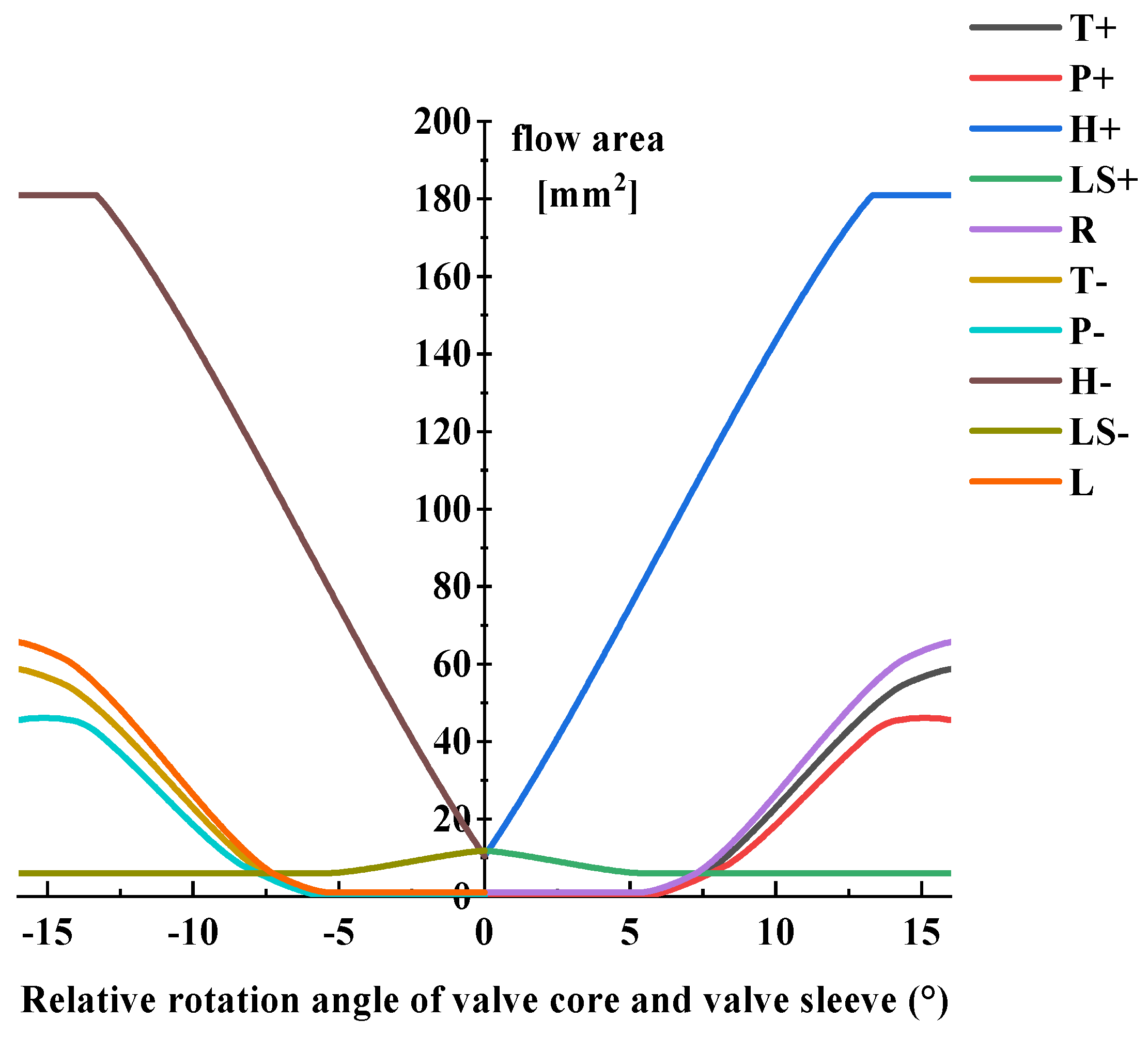
A right turn was taken as an example to illustrate the working principle of the hydrostatic steering unit. The steering wheel rotates clockwise to provide torque to the hydrostatic steering unit. The spool and the valve sleeve are relatively displaced, the P port of the hydrostatic steering unit is opened, the oil enters the metering motor through the P port, and the metering motor starts to rotate. The high-pressure oil is input to the right steering cylinder through the A port of the hydrostatic steering unit to push it out to perform the right steering action of the loader, while the left steering cylinder is retracted in the process, and the oil flows back to the fuel tank through the T port of the hydrostatic steering unit. At the same time, the metering motor drives the valve sleeve to rotate together through the linkage shaft to become a follow-up system. Only when the steering wheel continues to rotate, the valve port of the hydrostatic steering unit can maintain a certain degree of opening. When the steering wheel rotates fast, the valve opening of the hydrostatic steering unit is large, and the steering is fast; the steering wheel rotates to the limit position, the cylinder extends (retracts) to the limit stroke, the steering angle of the loader reaches the maximum, and the position feedback control is formed. The relative flow area of the valve core and valve sleeve corresponding to each valve port of the hydrostatic steering unit is shown in
Figure 4.
3. Analysis of Vibration Mechanism
The steering vibration of the loader not only affects the comfort of the driver, but also affects the normal operation of the loader by the driver, thereby reducing the safety of work. At the same time, vibration also affects the hydraulic system, causing the low-pressure cavity of the hydrostatic steering unit to be emptied, reducing the life and stability of the hydraulic system. In order to analyze the steering vibration mechanism better, a steering emergency stop test was carried out. The test site is a flat asphalt road. During the test, the pressure signals at the A and B ports of the hydrostatic steering unit and the lateral acceleration signal of the cab were collected and recorded synchronously.
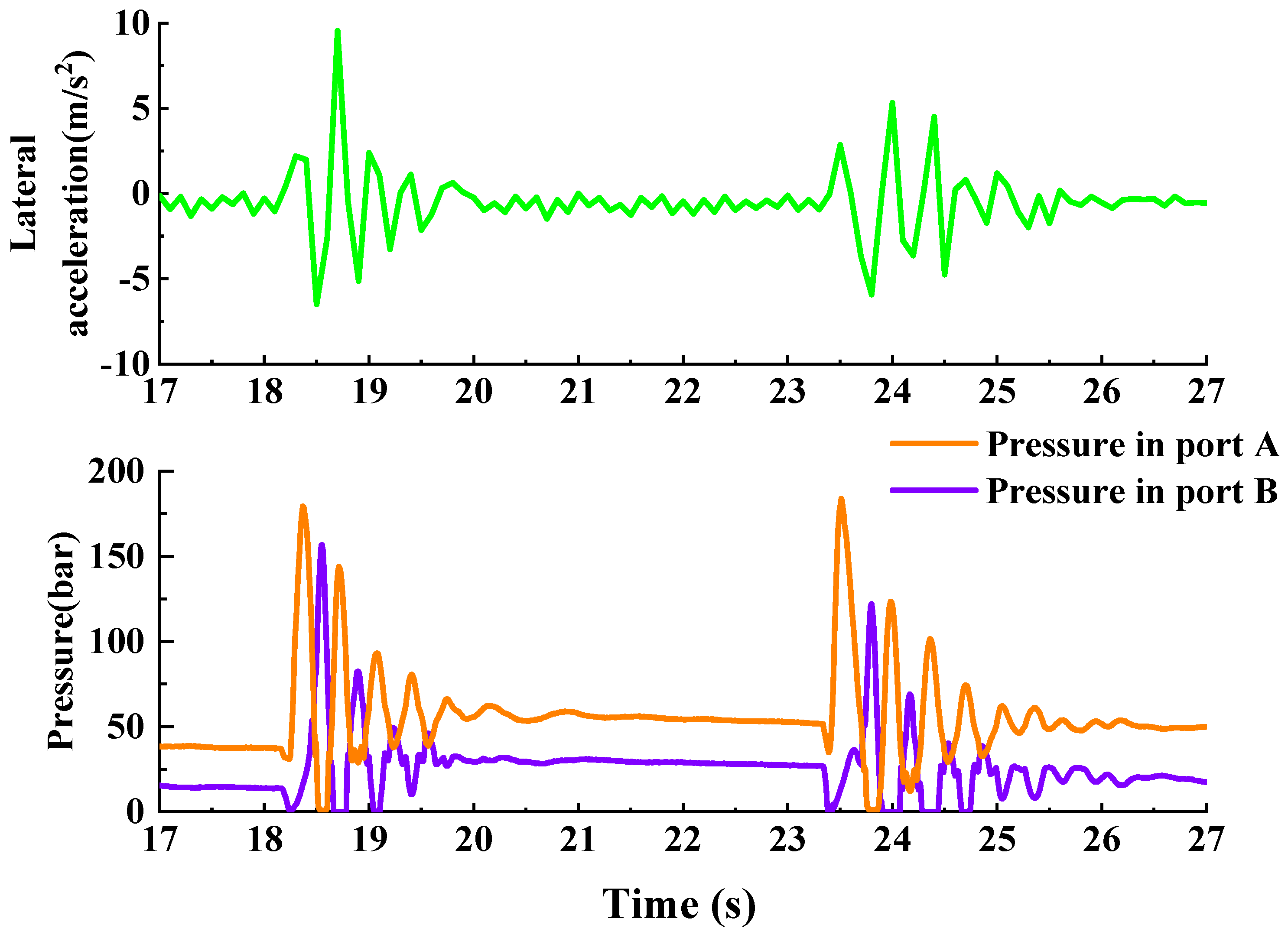
The steering emergency stop test refers to turning the steering wheel 120 degrees at the fastest speed (80 r/min), then releasing it. The test results are shown in
Figure 5, and the first emergency stop test in the figure was used as an example for analysis. At 18.2 s, the loader performs a left steering action, the pressure at port B of the hydrostatic steering unit rises to 180 bar, at the same time, the lateral acceleration of the cab rises. When the steering action is completed, the pressure at port B of the hydrostatic steering unit drops. The front frame of the loader continued to rotate, and the reverse acceleration of the cab increased to 8 m/s
2, causing the left steering cylinder to be squeezed. When turning to the end, the pressure at port A of the hydrostatic steering unit rises to 150 bar. Since the impact energy cannot be changed instantaneously, the front frame of the loader moves in the reverse direction, and the lateral acceleration of the cab rises up to 10 m/s
2. At the same time, the pressure of the left steering cylinder drops, the pressure of the right steering cylinder rises, and the peak pressure of the right steering cylinder is 130 bar. The previous movement of shaking the frame from side to side was repeated twice and ended. The peak pressure of the first sloshing is 150 bar, and the peak pressure of the second sloshing is 100 bar. The cab acceleration changes 5 times (the cab swings back and forth 5 times). After 1.8 s, the pressure of the steering cylinder returned to a stable state, and the frame of the loader and the driver’s cab no longer shake.
For the processing and analysis of the test results, the steering vibration mechanism can be summarized as follows:
Striving to reduce the effort of the operator and the time wasted on turning the steering wheel, as well as to shorten the time of the working cycle and to increase the efficiency, causes the use of ever greater gain in the steering system. A side effect is the formation of ever greater lateral accelerations;
When the steering starts, the opening speed of the rotary valve port is faster. Then, the hydraulic oil output by the pump quickly flows into the system, causing a start-up shock;
The ports of the hydrostatic steering unit closes quickly when the steering stops suddenly, and the deformation of the elastic components such as the tires and the shock absorber pad of the cab will produce a large inertial impact. The pressure shock could not be released, causing the front frame and cab to swing repeatedly.
4. System Simulation Model Verification
In the previous research of hydraulic components or systems, it was necessary to establish a mathematical model of the research object, and then establish the model in Matlab/Simulink according to its transfer function, and finally simulate and analyze its dynamic characteristics. However, in the research of this article, on the one hand, due to the complex structure of the hydrostatic steering unit, it was difficult to convert the relevant physical quantities into a mathematical model; on the other hand, the pressure-flow characteristics of the hydrostatic steering unit are non-linear. It takes a long time and is not accurate enough to analyze the dynamic characteristics of the anti-reverse valve through the linear simplified transfer function in Matlab. AMESim is based on physical model modeling, and performs physical modeling of components or systems from the bottom instead of refining mathematical models. Through its powerful analysis capabilities, the simulation accuracy of hydraulic components is greatly improved. Therefore, according to the structure and working principle of the full hydraulic steering system of the loader, the simulation model was built through the HCD library of AMESim.
In order to establish the dynamic model of the hydraulic steering system, the hydrostatic steering unit was transformed into a sliding slide valve through the AMESim software. The valve core and valve sleeve along the axial generatrix of the mating surface are unfolded, so that the rotation becomes translation. The spool and sleeve of the spool valve in the AMESim model are the spool and sleeve of the rotary valve. The parameters in the model remain the same as the actual structure size, and the working process of the model is consistent with the actual working conditions. The expanded view is shown in
Figure 2: the thin solid line is the groove on the valve core, and the thick solid line is the hole of the valve sleeve. The translation of the spool valve is equivalent to the relative rotation of the spool and sleeve of the rotary valve. The parameters of equivalent metering motor are calculated from the displacement of the motor, the stroke of the steering cylinder and the number of turns of the steering wheel. The calculation process is as follows:
where
n is the maximum steering wheel rotation in one direction;
D is the steering cylinder diameter;
d is the steering cylinder piston rod diameter;
l is the cylinder stroke;
V is the rotary valve displacement;
dis is the slide valve displacement;
d1 is the hydraulic steering unit diameter;
dm is the piston cylinder diameter of equivalent metering motor.
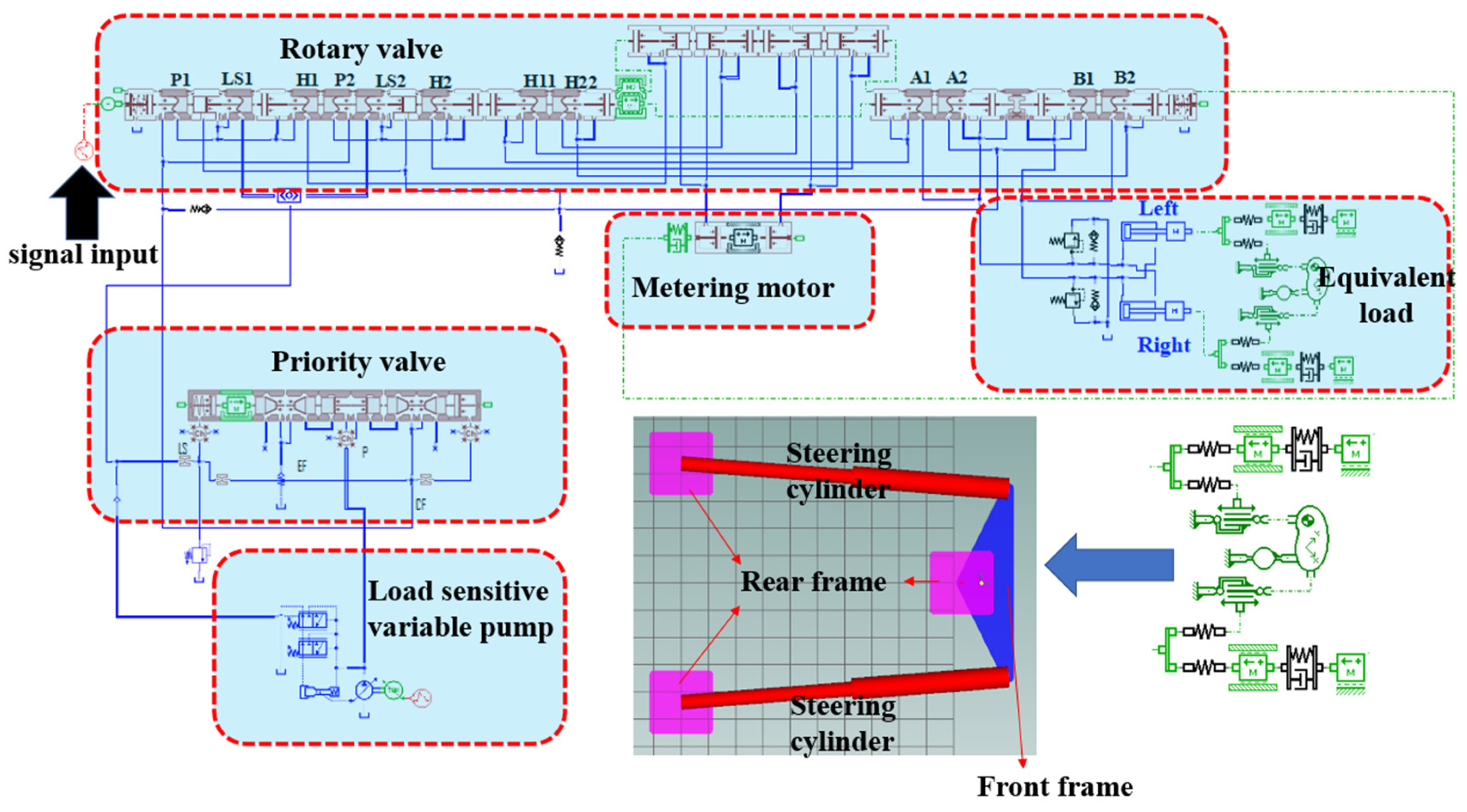
In order to accurately model the load, the components in the 2D Mechanical library of AMESim were used and the hinge point coordinates were set to determine the relative position of the cylinder and the front and rear frames. In the simulation, the tire stiffness and force are equivalent through mass and spring damping [
23,
24]. The AMESim model of the loader’s hydraulic steering system is shown in
Figure 6. For the study of the dynamics of the system, the gain in the system is extremely important. The system gain is described as follows: The loader turns from the left end to the right end corresponding to 5 turns of the steering wheel. The key component parameters of the hydraulic steering system are shown in
Table 1.
In order to verify the correctness of the simulation model, an emergency steering action experiment (same as the experiment in
Section 3) was performed, in which the steering wheel was turned 120 degrees at the fastest speed and then released. The comparison between simulation and the test results is shown in
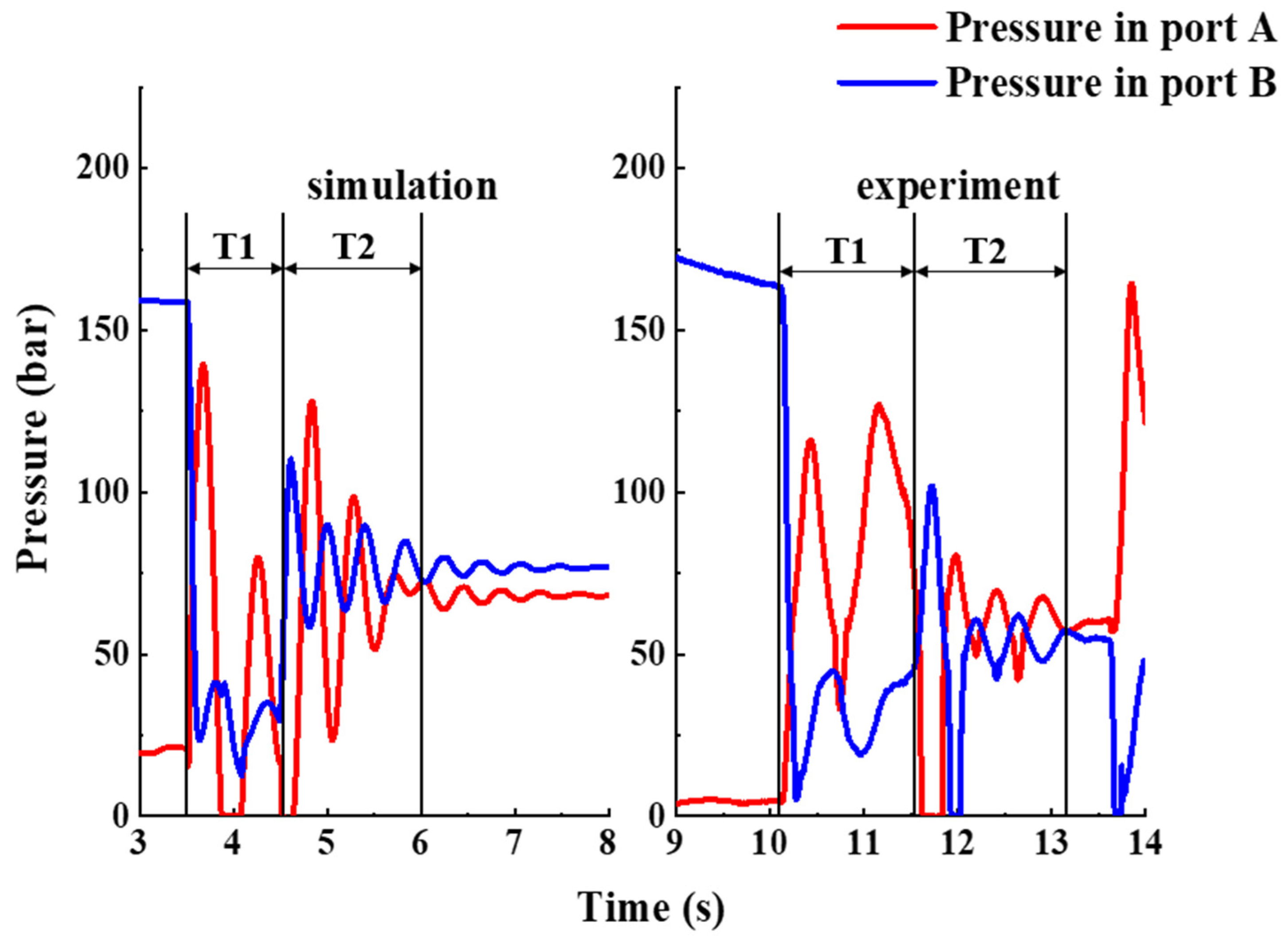
Figure 7. T1 is the steering process of the loader, and T2 is the pressure fluctuation process at the end of the steering. It can be obtained from the figure that the actual steering action time is 1.5 s, the pressure fluctuation time after the steering is completed is 1.5 s, and the corresponding simulation time is 1.2, 1.7 s. The simulation of the steering process has the same movement trend as the test pressure curve. The pressure of port A first rises, then drops, and finally rises. The difference is that the actual steering pressure amplitude is 125 bar, and the corresponding simulated pressure amplitude is 135 bar. After the steering is completed, the simulation result shows that the pressure fluctuates 6 times with a fluctuation range of 0–125 bar. The actual prototype test pressure fluctuates 6 times with a pressure fluctuation range of 0–100 bar. And in the simulation and actual prototype test, the phenomenon of air suction has appeared. After comparing the results, the simulation results are consistent with the prototype test in trend, and there are some differences in numerical values. In summary, the accuracy of the simulation model has reached 80% and can be used for subsequent simulation experiments.
5. The Structure and Principle of the Cushion Valve
The hydraulic steering system of the loader is complex and the structure is difficult to modify. In order to solve the problem of steering vibration, an electro-hydraulic proportional valve is added between the A and B ports of the hydrostatic steering unit. This method uses hydraulic means connecting A and B ports to quickly consume energy during the stop process. In the actual work process, pressure fluctuations are difficult to determine, electro-hydraulic proportional valves are difficult to control, and the steering system does not have a corresponding pressure acquisition and processing system. Therefore, a cushion valve was designed to solve the problem of steering stop vibration.
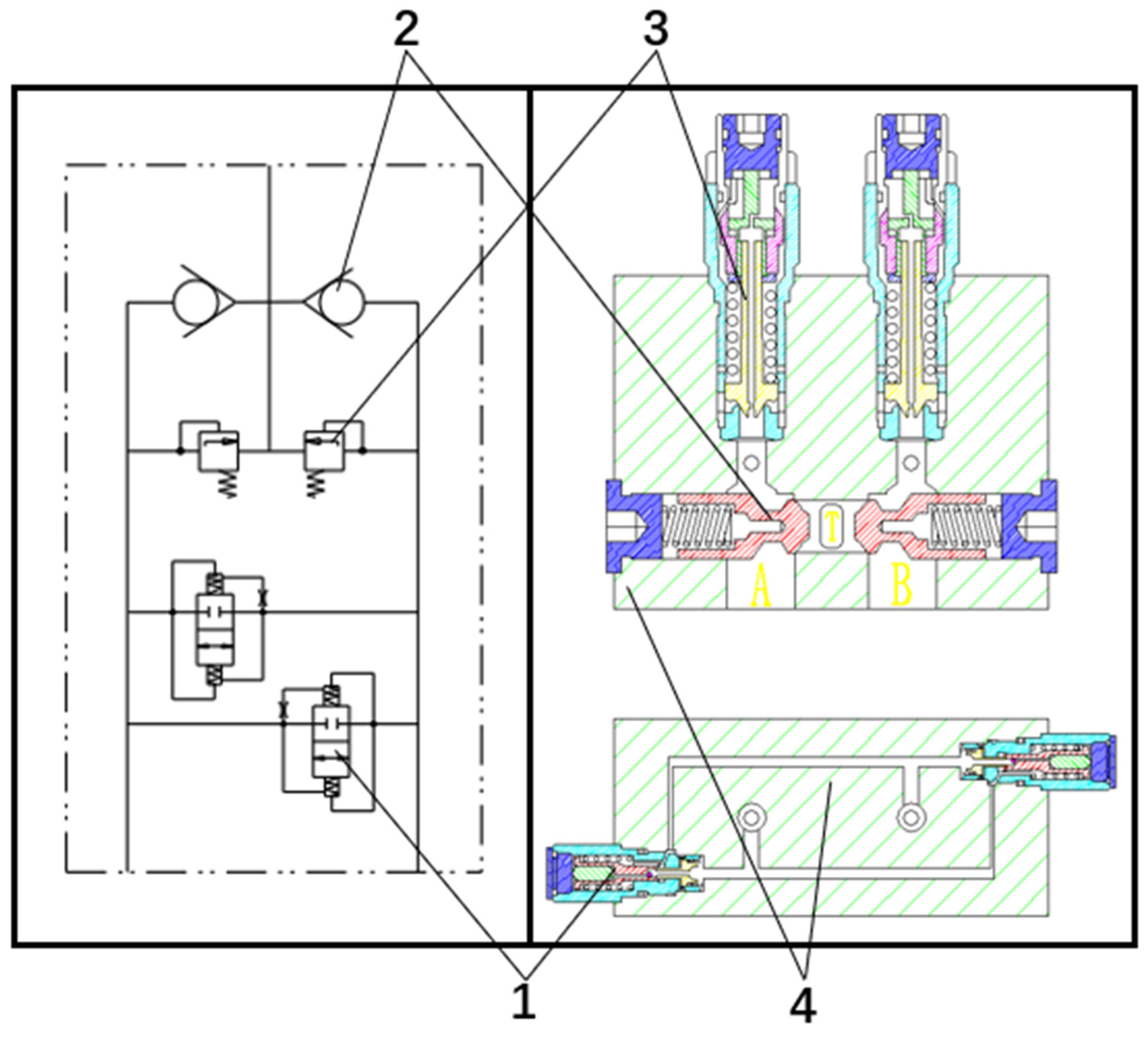
The control strategy of the cushion valve: (1) When the steering action is completed, the high-pressure chamber oil is led to the low-pressure side through the cushion. The cushion absorbs the pressure shocks and effectively suppresses the repeated swing of the front frame and the cab of the loader; (2) When the low-pressure cavity of hydrostatic steering unit is negative pressure caused by vibration, the oil is supplemented from the tank through the one-way valve; (3) At the beginning of the steering, when the starting shock is too large, the starting shock will be reduced by the secondary relief valve. The structure principle of the cushion valve is shown in
Figure 8. The A(B) port of the cushion valve is connected with the A(B) port of the rotary valve, and the T port is connected with the oil tank. The key component parameters of the cushion valve are shown in
Table 2.
The structure and working principle of the anti-vibration valve are complex, and its structure is shown in
Figure 9. The working principle is as follows: Port A and port B of the anti-vibration valve are respectively connected to the A and B ports of the steering gear. The high-pressure oil at port A and the low-pressure oil at port B were used as an example for analysis. The pressure oil enters the action chamber of the piston 8 through the hole in the valve seat 2, the ball valve 5 and the hole in the plunger 6. Overcoming the force of springs 1 and 7, the valve seat and plunger move to the left together. When the pressure reaches P
S, the steering action is completed and the pressure drops. If there is no anti-vibration valve, recoil and oscillation will occur due to the energy storage effect of the hydraulic system. When P < P
S, the plunger moves to the right under the force of the spring 7, and the valve seat is delayed due to the damping effect of the orifice 3. At this time, A is connected to B, and the high-pressure oil in A flows to B, causing the oil pressure in A to drop quickly.
6. Simulation and Prototype Test
In order to better verify the optimization effect of the buffer valve on the steering performance of the wheel loader, the following simulation and prototype tests were carried out. The simulation and prototype test are comparison tests between the initial system and the system equipped with the cushion valve for steering emergency stop and swing steering wheel.
6.1. Function Verification Simulation Experiment of Cushion Valve
The simulation is a comparative test between the initial system and the system equipped with the cushion valve to simulate the emergency stop of the steering and swing steering wheel test. The steering emergency stop test refers to turning the steering wheel 120 degrees at the fastest speed, then releasing it. The swing steering wheel test refers to a test in which the torque applied to the steering wheel is: 0.5 s clockwise −0.5 s counterclockwise −0.5 s clockwise −0.5 s counterclockwise. The result is the steering angle of the loader and the pressure at the A and B ports of hydrostatic steering unit. The steering angle refers to the angle between the axis of the front frame and the rear frame of the loader.
The emergency stop of the steering simulation result is shown in
Figure 10. The cushion valve greatly reduces the vibration of the loader’s steering stop. The performance is: The range of pressure fluctuation is reduced from 50 bar to 30 bar, and the number of pressure fluctuations is reduced from 6 times to once. When the steering is completed, the front frame is reduced from vibration 6 times to 0, and the vibration time is reduced from 1.5 s to 0.
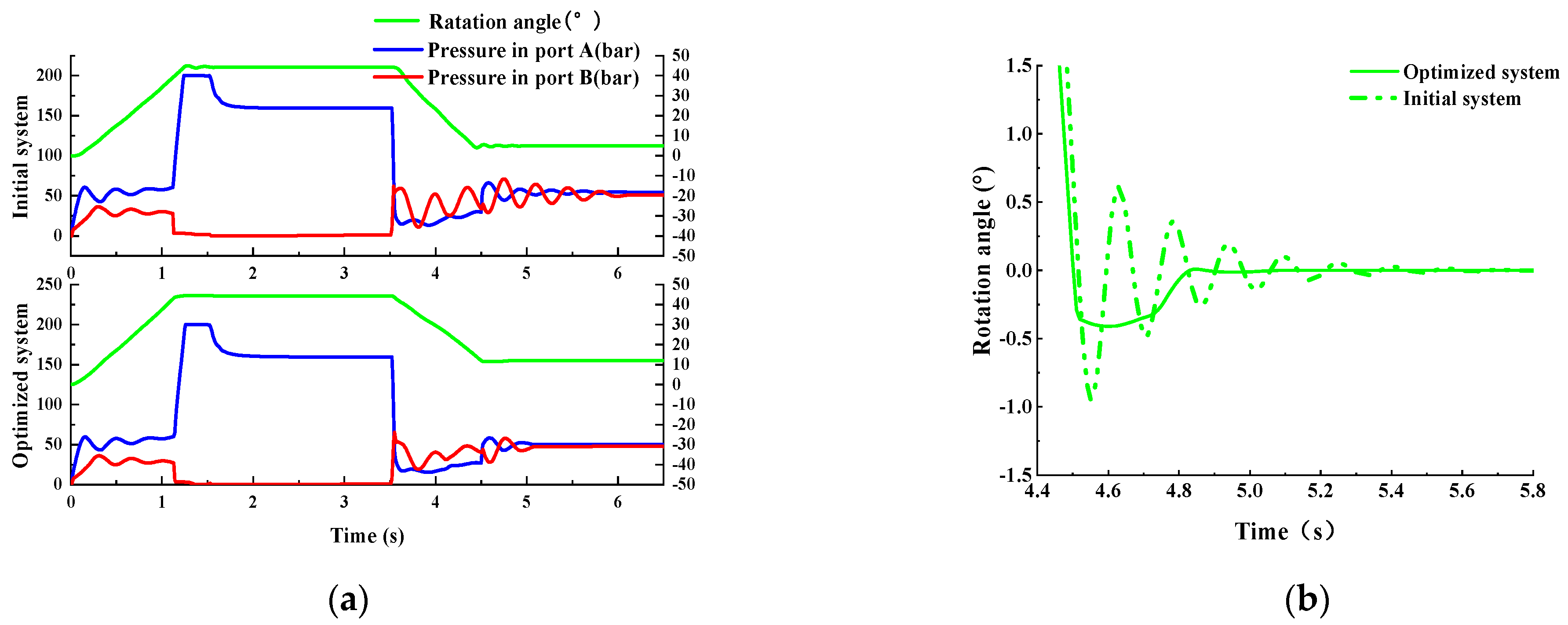
The swing steering wheel simulation result is shown in
Figure 11. After analyzing the simulation results, the cushion valve greatly reduces the pressure start shock and steering stop vibration of the loader. The main performance is: the starting impact pressure is reduced from 190 bar to 80 bar, the pressure fluctuation range is reduced from 130 bar to 30 bar, the number of pressure fluctuations is reduced from 9 to 2, the number of vibrations of the front frame is reduced from 9 to 1, and the vibration time is reduced from 2.1 s is reduced to 0.4 s. The original system still had pressure fluctuations and cab vibration during 5–6 s, but the optimized system no longer had pressure fluctuations and cab vibrations for 5–6 s.
In summary, the comparative simulation test verifies that the cushion valve has a significant improvement effect on pressure start shock and pressure fluctuation. The cushion valve can be used to optimize the hydraulic steering system of the wheel loader.
The swing steering wheel simulation result is shown in
Figure 11. After analyzing the simulation results, the cushion valve greatly reduces the pressure start shock and steering stop vibration of the loader. The main performance is: the starting impact pressure is reduced from 190 bar to 80 bar, the pressure fluctuation range is reduced from 130 bar to 30 bar, the number of pressure fluctuations is reduced from 9 to 2, the number of vibrations of the front frame is reduced from 9 to 1, and the vibration time is reduced from 2.1 s is reduced to 0.4 s.
In summary, the comparative simulation test verifies that the cushion valve has a significant improvement effect on pressure start shock and pressure fluctuation. The cushion valve can be used to optimize the hydraulic steering system of the wheel loader.
6.2. Prototype Comparison Test
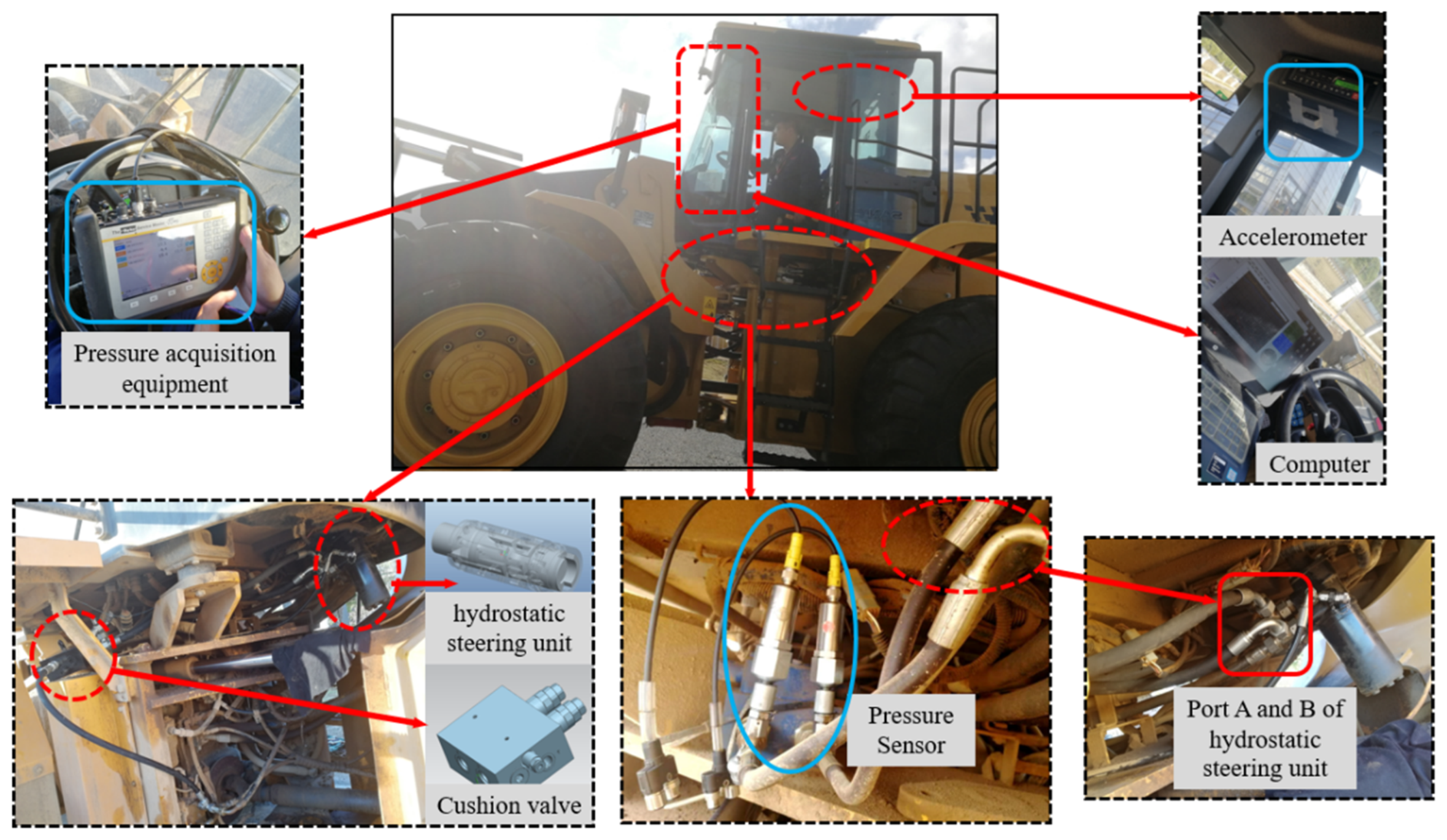
In order to accurately analyze the impact of the cushion valve on the steering system of the loader and study the optimization function of the steering stop vibration, it was necessary to install the cushion valve on the steering system of the loader to conduct a prototype test. The test prototype is still the 5-ton loader used in the previous test, and the test site is a flat asphalt road. For the severity of vibration, on the one hand, the driver’s feeling is subjectively judged; on the other hand, it is objectively judged by data. Since the driver’s subjective feelings cannot be quantified, this article uses pressure and acceleration to evaluate the steering effect. Therefore, pressure sensors are installed on the A and B ports of the hydraulic steering unit, and an accelerometer is arranged in the cab to measure and record the lateral acceleration of the loader. The sample vehicle test site and sensor installation location are shown in
Figure 12. The test records, processes and analyzes the data by synchronously collecting the A and B port pressures of the hydraulic steering unit and the lateral acceleration signals of the cab. Through the observation results, the effect of the buffer valve on the optimization of the steering system of the loader is demonstrated. That is, the greater the pressure fluctuation of the steering cylinder, the greater the vibration amplitude of the loader frame, and the greater the lateral acceleration fluctuation of the cab, the more intense the vibration of the cab. Conversely, small pressure fluctuations and small accelerations prove that the vibration impact is small and the optimization effect is obvious.
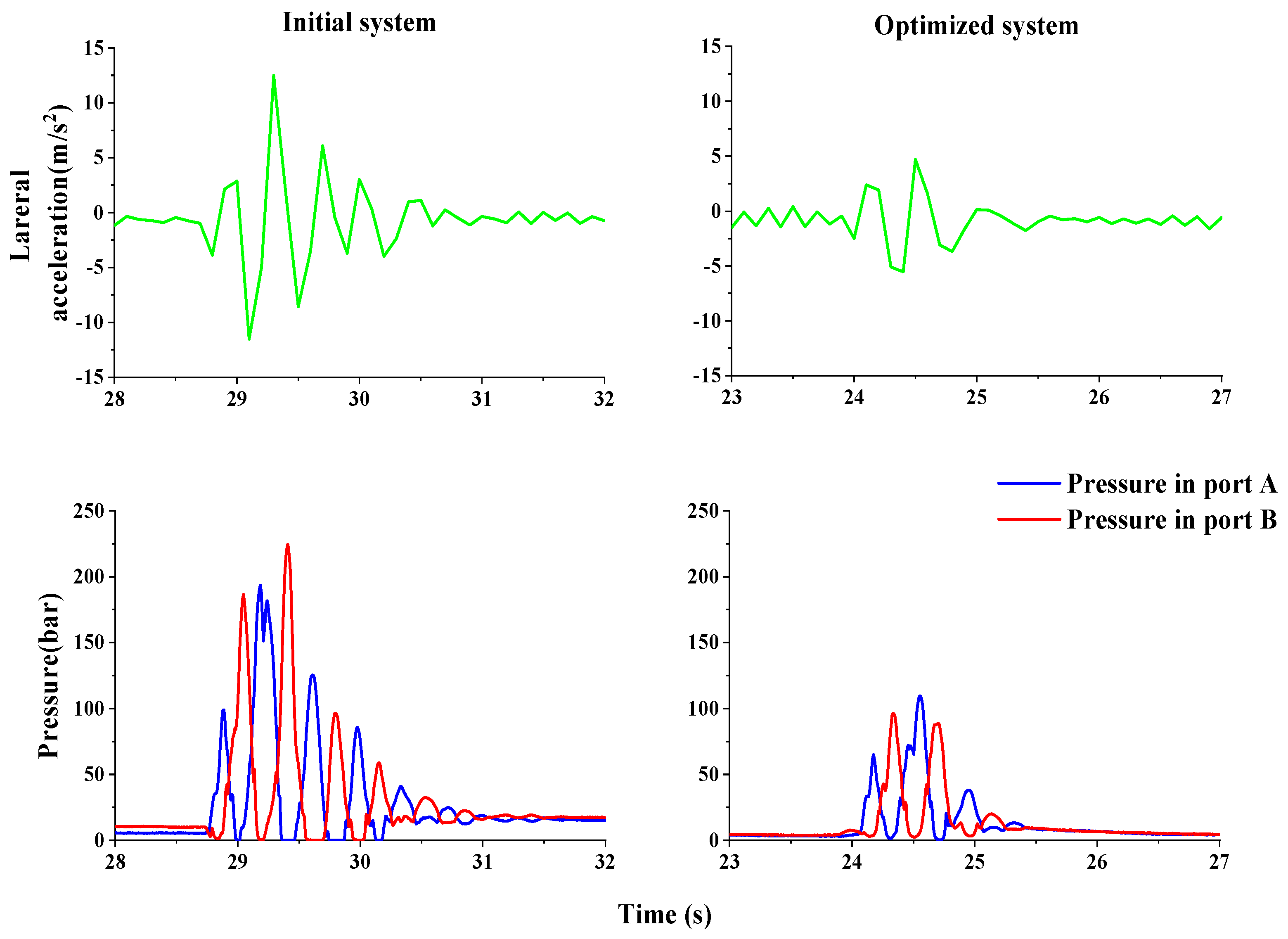
The test results are shown in
Figure 13. Compared with the test results of the original steering system loader, the pressure start shock at the beginning of the steering is reduced from 180 bar to 80 bar, and the pressure fluctuation after the sudden stop of the steering is reduced from twice to 0. The vibration amplitude of the cab is significantly reduced, and the acceleration range is reduced from 10 m/s
2 to 2 m/s
2. That is, the front frame of the loader stops shaking after swinging in the reverse direction after the steering stop action ends. It is verified by experiments that this hydraulic method has solved the problem of the loader’s steering vibration and suction. Also, it greatly reduced the start-up shock without affecting other operations.
In order to test the cushion valve’s ability to absorb pressure shocks, a swing steering wheel comparison test was carried out. The swing steering wheel test refers to a test in which the torque applied to the steering wheel is: 0.5 s clockwise-0.5 s counterclockwise-0.5 s clockwise-0.5 s counterclockwise, so that the hydraulic steering unit performs multiple open-close-open tests. This test is different from the emergency stop test in that it will quickly open and close the steering gear many times. It can make the energy of multiple pressure pulses unable to be released, causing the system to vibrate violently, which can better reflect the function of the cushion valve to absorb pressure shocks and its dynamic characteristics.
The test results of the swing steering wheel are shown in
Figure 14. Swing the steering wheel four times, the oil pressure in the steering gear rises up to 100 bar, and the lateral acceleration of the cab is up to 5 m/s
2. After the operation is completed, the front frame of the loader stops swinging after a reverse reversal, and the pressure at the A and B ports of the steering gear fluctuates once, and the fluctuation duration is 0.3 s. That is, the front frame of the loader stops shaking after swinging in the reverse direction after the steering stop action ends. Compared with the test results of the original steering system loader, the buffer valve reduces the pressure start shock at the beginning of the steering from 250 bar to 100 bar, the pressure fluctuation after the steering emergency stop is reduced from 4 times to 1 time, and the vibration amplitude of the cab is significantly reduced. The main performance is: the acceleration change range is reduced from 14 m/s
2 to 5 m/s
2.
7. Discussion and Conclusions
Through system theory analysis, modeling simulation and prototype test, it is found that the loader steering stop vibration mechanism: when the steering stops, the hydraulic steering unit oil port opens and closes quickly. The deformation of elastic components such as tires and cab cushions produces large inertial shocks, and the pressure shocks cannot be released, causing repeated swings of the vehicle body and the cab;
Design a cushion valve that solves the problem: the secondary relief valve reduces the start-up shock, the anti-vibration valve reduces the impact of pressure fluctuations, and the one-way valve replenishes the oil to solve the problem of air suction;
The simulation analysis of the cushion valve and the loader shows that the loader’s steering start shock is reduced, the steering stop pressure fluctuation is reduced, and the body vibration is weakened;
The prototype test and analysis show that the buffer valve has a significant effect on the optimization of the full hydraulic steering system of the loader. The main performance is: the pressure start shock at the beginning of the steering is reduced by 50%, the steering stop vibration is reduced by 75%, and the phenomenon of suction is no longer present.
In summary, the pressure fluctuation suppression strategy of the hydraulic steering system proposed in this paper is extremely innovative and effective. The wheel loader vibration problem was reliably solved, which greatly improved the steering stability of the loader. The strategy will provide technical support and guidance to the field of hydraulic steering, and can be used for the design and optimization of the hydraulic steering systems of engineering vehicles.
Author Contributions
Conceptualization, T.W. and Y.W.; methodology, T.W.; software, Y.W.; validation, Z.L., Z.Z. and R.L.; formal analysis, Y.W.; investigation, T.W.; resources, T.W.; data curation, Y.W.; writing—original draft preparation, Y.W.; writing—review and editing, T.W.; visualization, T.W.; supervision, T.W.; project administration, L.Z.; funding acquisition, L.Z. All authors have read and agreed to the published version of the manuscript.
Funding
This research received no external funding.
Conflicts of Interest
The authors declare no conflict of interest.
References
- Yang, L.W. Development of Control System of Wheel Type Backhoe Loader. In Proceedings of the International Conference on Soft Computing Techniques and Engineering Application (ICSCTEA), Kunming, China, 25–27 September 2013; pp. 87–95. [Google Scholar]
- Ning, X.B.; Shen, J.S.; Meng, B. Co-simulation of Wheel Loader Working Mechanism. In Proceedings of the 6th China-Japan International Conference on Mechatronics (CJCM 2010), Zhenjiang, China, 10–12 September 2010; pp. 72–77. [Google Scholar]
- Rane, A.K.; Kumar, S.; Maheshwari, S. Literature Review on Analysis of Wheel Loader and Its Various Components. In Proceedings of the 8th International Conference on Materials Processing and Characterization (ICMPC), Hyderabad, India, 16–18 March 2018; pp. 19049–19055. [Google Scholar]
- Elezaby, A.A.; Abdelaziz, M.; Cetinkunt, S. Operator Model for Construction Equipment. In Proceedings of the IEEE/ASME International Conference on Mechatronic and Embedded Systems and Applications, Beijing, China, 12–15 October 2008; p. 582. [Google Scholar]
- Li, X.; Wang, G.; Yao, Z.; Qu, J. Dynamic model and validation of an articulated steering wheel loader on slopes and over obstacles. Veh. Syst. Dyn. 2013, 51, 1305–1323. [Google Scholar] [CrossRef]
- Wang, H.Q.; Xiao, X.; Luo, X.R. Optimum Design of Wheeled Loader’s Steering Rubber Buffer Seat Based on ANSYS. In Proceedings of the 2nd International Conference on Manufacturing Science and Engineering, Guilin, China, 9–11 April 2011; pp. 1217–1222. [Google Scholar]
- Xu, H.; Song, Y.; Lu, Z.; Zhao, M. Transmission ratio research of hydraulic steering by-wire system. In Proceedings of the International Forum on Mechanical and Material Engineering (IFMME 2013), Guangzhou, China, 13–14 June 2013; p. 455. [Google Scholar]
- Mantaras, D.A.; Luque, P. Virtual test rig to improve the design and optimisation process of the vehicle steering and suspension systems. Veh. Syst. Dyn. 2012, 50, 1563–1584. [Google Scholar] [CrossRef]
- Simionescu, P.A.; Beale, D.; Talpasanu, I. Dynamic effect of the bump steer in a wheeled tractor. Mech. Mach. Theory 2007, 42, 1352–1361. [Google Scholar] [CrossRef]
- Zhao, H.; Lv, Z. Research on Angle Measurement of Loader’s Steering-by-Wire System. In Proceedings of the International Conference on Mechatronics, Robotics and Automation (ICMRA 2013), Guangzhou, China, 13–14 June 2013; pp. 138–141. [Google Scholar]
- Cao, B.; Liu, X.; Chen, W.; Zhou, C.; Xu, F. Mechanism analysis of pressure fluctuation in wheel loader articulated steering hydraulic system. J. Mech. Sci. Technol. 2020, 34, 4137–4147. [Google Scholar] [CrossRef]
- Zardin, B.; Borghi, M.; Gherardini, F.; Zanasi, N. Modelling and Simulation of a Hydrostatic Steering System for Agricultural Tractors. Energies 2018, 11, 230. [Google Scholar] [CrossRef] [Green Version]
- Du, Y.X. Steering stability analysis of the nonlinear damping hydraulic system of an articulated wheel loader. Constr. Mach. 2009, 40, 57–61. [Google Scholar]
- Zhao, F. Mechanical-Hydraulic Co-Simulation and Experimental Research on Loader Full Hydraulic Steering System. Master’s Thesis, Jilin University, Jilin, China, 2012. [Google Scholar]
- Jin, T.; Li, P.; Zhao, L.; Du, X.; Ma, X. Optimization of Hydrodynamic and Hydrostatic Steering Control System Based on GA-PID. In Proceedings of the 22nd Chinese Control and Decision Conference, Xuzhou, China, 26 May–28 August 2010; p. 3180. [Google Scholar]
- Dell’Amico, A.; Krus, P. Modeling, Simulation, and Experimental Investigation of an Electrohydraulic Closed-Center Power Steering System. IEEE ASME Trans. Mechatron. 2015, 20, 2452–2462. [Google Scholar] [CrossRef] [Green Version]
- Xu, F.; Liu, X.; Chen, W.; Zhou, C.; Cao, B. Fractional order PID control for steer-by-wire system of emergency rescue vehicle based on genetic algorithm. J. Cent. South Univ. 2019, 26, 2340–2353. [Google Scholar] [CrossRef]
- Oh, K.; Kim, H.; Ko, K.; Kim, P.; Yi, K. Integrated wheel loader simulation model for improving performance and energy flow. Autom. Constr. 2015, 58, 129–143. [Google Scholar] [CrossRef]
- Rigotti-Thompson, M.; Torres-Torriti, M.; Auat Cheein, F.; Troni, G. Ground Disturbance Rejection Approach for Mobile Robotic Manipulators with Hydraulic Actuators. In Proceedings of the 25th IEEE/RSJ International Conference on Intelligent Robots and Systems (IROS), Madrid, Spain, 1–5 October 2018; pp. 5980–5986. [Google Scholar]
- Mitov, A.; Angelov, I.; Kralev, J. Embedded Electrohydraulic Controller with Digital Valve Actuation for Steering of Heavy Duty Machines. In Proceedings of the 7th Mediterranean Conference on Embedded Computing (MECO), Budva, Montenegro, 10–14 June 2018; pp. 99–102. [Google Scholar]
- Daher, N.; Ivantysynova, M. An Indirect Adaptive Velocity Controller for a Novel Steer-by-Wire System. J. Dyn. Syst. Meas. Control Trans. ASME 2014, 136, 051012. [Google Scholar] [CrossRef]
- Haggag, S.; Alstrom, D.; Cetinkunt, S.; Egelja, A. Modeling, control, and validation of an electro-hydraulic steer-by-wire system for articulated vehicle applications. IEEE ASME Trans. Mechatron. 2005, 10, 688–692. [Google Scholar] [CrossRef]
- Chung, Y.K.; Park, S.H.; Jeong, C.S.; Jeong, Y.M.; Yong, Y.S. A Study on Modeling and Simulation of Hydraulic System for a Wheel Loader using AMESim. J. Drive Control 2010, 7, 1–8. [Google Scholar]
- Zhu, Q.; Liu, G.; Song, D. The Study of Dynamic Characteristic of Full Hydraulic Power Steering System Based on AMESim. In Proceedings of the 3rd International Conference on Manufacturing Science and Engineering (ICMSE 2012), Xiamen, China, 27–29 March 2012; p. 474. [Google Scholar]
| Publisher’s Note: MDPI stays neutral with regard to jurisdictional claims in published maps and institutional affiliations. |
© 2022 by the authors. Licensee MDPI, Basel, Switzerland. This article is an open access article distributed under the terms and conditions of the Creative Commons Attribution (CC BY) license (https://creativecommons.org/licenses/by/4.0/).


