Article

The Effects of Permanent Magnet Segmentations on Electromagnetic Performance in Ironless Brushless DC Motors

1
School of Mechanical Engineering, Yanshan University, Qinhuangdao 066004, China
2
School of Automation, Beijing Institute of Technology, Beijing 100081, China
3
Beijing Institute of Aerospace Control Devices, Beijing 100039, China
4
Inner Mongolia North Heavy Industries Group CORP.LTD, NORINCO GROUP, Baotou 014033, China
5
NO. 703 Research Institute of China State Shipbuilding Company Limited, Harbin 150001, China
*
Author to whom correspondence should be addressed.
Energies 2022, 15(2), 621; https://doi.org/10.3390/en15020621
Submission received: 22 October 2021 / Revised: 19 December 2021 / Accepted: 5 January 2022 / Published: 16 January 2022
(This article belongs to the Special Issue Advanced Electrical Machine Design and Optimization)

Abstract

:
This paper investigates the electromagnetic torque by considering back electromagnetic force (back-EMF) trapezoidal degrees of ironless brushless DC (BLDC) motors through the two-dimensional finite element method (2-D FEM). First, the change percentages of the electromagnetic torque with back-EMF trapezoidal degrees, relative to those of PMs without segments, are investigated on the premise of the same back-EMF amplitude. It is found that both PM symmetrically and asymmetrically segmented types influence back-EMF trapezoidal degrees. Second, the corresponding electromagnetic torque, relative to that of PMs without segments, is studied in detail. The results show that the electromagnetic torque can be improved or deteriorated depending on whether the back-EMF trapezoidal degree is lower or higher than that of PMs without segments. Additionally, the electromagnetic torque can easily be improved by increasing the number of PMs’ symmetrical segments. In addition, the electromagnetic torque in PMs with asymmetrical segments is always higher than that of PMs without segments. Finally, two ironless PM BLDC motors with PMs symmetrically segmented into three segments and without segments are manufactured and tested. The experimental results show good agreement with those of the 2-D FEM method. This approach provides significant guidelines to electromagnetic torque improvement without much increase in manufacturing costs and process complexity.

1. Introduction

With the merits of simple structure, easy control, fast transient response, and high efficiency, permanent magnet brushless DC (PM BLDC) motors have been widely used in different areas and applications, such as electric vehicles, energy storage flywheels, robots, household appliances, etc. [1,2,3,4,5,6,7]. However, with the increasing requirements of energy efficiency and high performance of equipment, conventional PM BLDC motors cannot meet the demands of high efficiency and high torque density any longer [8,9]. The lightweight ironless PM BLDC motor eliminates the stator iron loss and, therefore, has a great potential in torque density improvement [10,11,12]. Additionally, in order to obtain the maximum output torque, the back electromagnetic force (back-EMF) waveform of the PM BLDC motor should be square or rectangular [13,14]. However, it is found that the back-EMF waveform of the designed ironless BLDC motor is much more sinusoidal in practice [15]. It has been proved in [16] that, in conditions of the same ideal square wave input currents and same back-EMF amplitudes, the electromagnetic torque with square back-EMF waveform is 15.5% higher than that with sinusoidal waveforms. This indicates that the more trapezoidal degree the back-EMF has, the higher the load torque will be, and the lower the resulting torque ripple.
In [15,17], it is highlighted that, due to the nonideality of magnetic material, design considerations, and manufacturing limitations, the real back-EMF waveform is not exactly trapezoidal, which deteriorates the electromagnetic torque. The trapezoidal degree of back-EMF can be obtained through different control strategies [15,17,18,19,20,21,22,23,24]. In [15], a phase current injection method is proposed to compensate for the nonideal back-EMF. In [17], a current optimization control method is proposed to reduce the torque ripple of PM BLDC motors, which is caused by the nonideal trapezoidal back-EMF. It is declared in [22] that the torque ripple can be reduced by the optimization of the phase rectification error, which is not inevitable in motor sensorless control. In [23], an average torque control strategy with a single period is proposed to minimize the torque ripple, and back-EMF is nonideal. In [24], a second-order sensorless control strategy for a BLDC motor system with low inductance and nonideal back-EMF is adopted to improve the reliability of current commutation during high-speed operation and reduce the power consumption of high-speed steady-state operation. In [13], the PM thickness and migration angle of a double-layer brushless DC motor are optimized to make the back-EMF waveform of the inside and outside stator winding consistent with each other, and the torque ripple is decreased dramatically. The electromagnetic torque performance of the PM BLDC motor can be improved with some adopted control strategies. However, it will increase the complexity of the motor control system.
As is known, the back-EMF waveform depends directly on the magnetic field distribution in the coil region, which is excited from the rotor PMs. Thus, trapezoidal back-EMF can be obtained through PM segmentation with different magnetic field intensities. However, to the best of the authors’ knowledge, few papers focus on this aspect [2,25,26]. In [27], a method for the comprehensive optimal design of a slotless PM BLDC motor with surface-mounted magnets is proposed, to find the optimal geometries of the assumed motor. In [28], the dynamic response of a BLDC motor is determined using artificial intelligence, which provides guidance for multiparameter optimization of electromagnetic torque improvement. In this paper, a method for improving the back-EMF trapezoidal degree by PM’s different segmentation types is proposed. Additionally, in order to keep the amplitude of the back-EMF constant, the combination of different intensities of PM magnetization is adopted. Firstly, the modeling of the ironless BLDC motor and PMs with symmetrical and asymmetrical segments are established. Secondly, the cases with the same back-EMF amplitudes are calculated through a two-dimensional finite element method (2-D FEM) multiobjective optimization. Thirdly, the change percentages of the electromagnetic torque with the back-EMF trapezoidal degree, relative to PMs without segments, are investigated. Finally, two ironless BLDC motor prototypes, one with PMs symmetrically segmented into three segments and the other without segments, are manufactured and tested to validate the simulated results.

2. Modeling

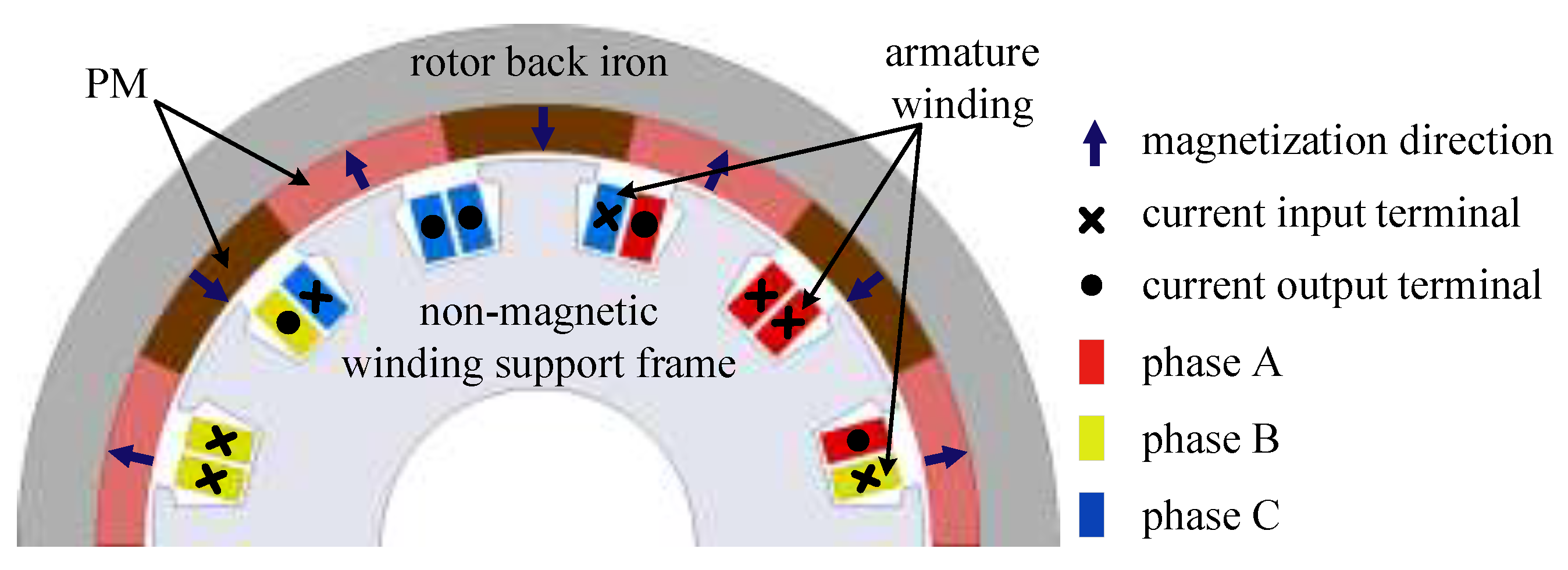
The 14-pole and 12-slot ironless BLDC motor equipped with an outer rotor is presented in Figure 1. And the specifications of all the symbols used in this paper, are tabulated in Nomenclature. The winding support frame is made of nonmagnetic material, such as epoxy resin or polyimide to reduce the weight. Additionally, the stator iron loss is eliminated, which is beneficial for torque density improvement. As the slot number per pole per phase is 2/7, concentrated windings with all teeth wounded were adopted. The outer rotor structure provides higher inertia than the inner rotor configuration under the same conditions. Additionally, it can be easily connected with external interfaces. The main magnetic field is excited by PMs. The solid arrows on the PMs show the corresponding radial magnetizing direction. As evident, the magnetization directions of each adjacent two PMs are inverse with each other. The embrace equals 1, which means the inner side of the rotor back iron is covered by PMs.
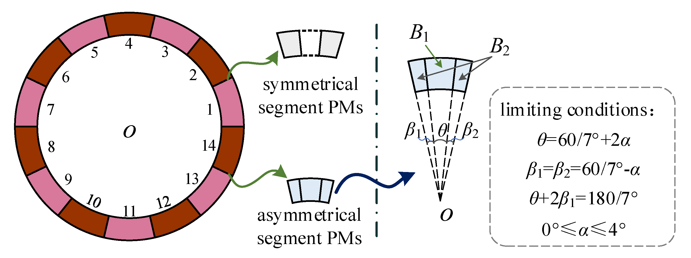
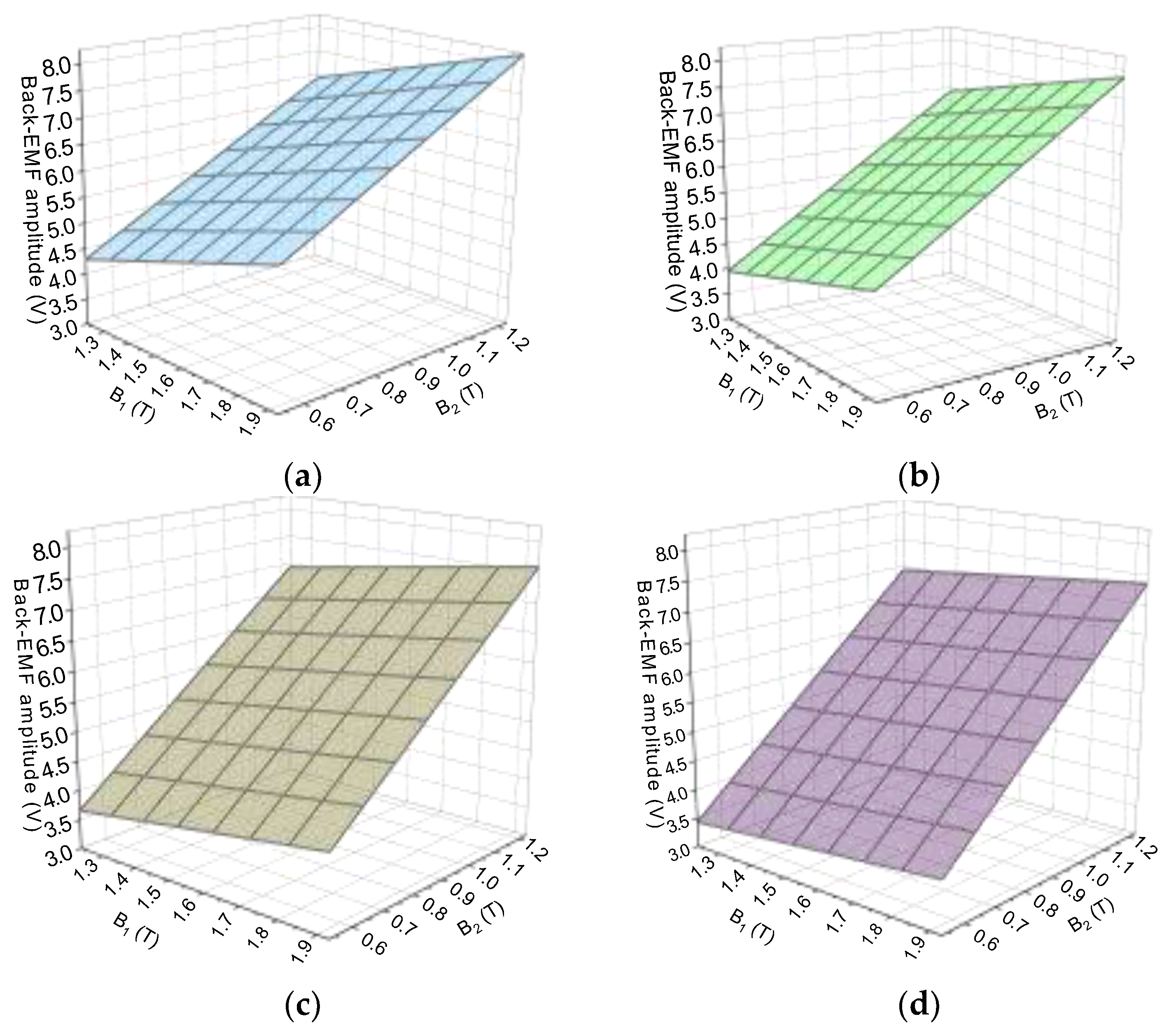
In order to obtain trapezoidal back-EMF, PMs were segmented symmetrically and asymmetrically, as illustrated in Figure 2. For the case of PMs segmented symmetrically, PMs were segmented into several equal sub-PMs. Here, the number of the symmetrically segmented PMs is denoted as 2k + 1 (k = 1, 2, 3). The sum of the sub-PM center angles is π/p. The remanence of the middle PM (mid-PM for short) is recorded as B1, and then taking the mid-PM as a reference, the remanence of the left or right side PMs (side-PMs for short) is denoted as B2, B3, …, Bk (k = 2, 3, 4) in sequence. The remanences of the side-PMs at the symmetric position are consistent with each other. While for the other case of PMs segmented asymmetrically, PMs were segmented into three sub-PMs. The central angle of the middle PM is set as θ, and that of the sub-PMs on both sides is assumed as β1 and β2, respectively. As shown in Figure 1, the inner side of the outer rotor is full of PMs without segmentations. Hence, restricted conditions were made to keep the embrace of PMs segmented into several sub-PMs to be 1. For symmetrically segmented PMs, θ = β1 = β2 = 60/7°, while for those with asymmetrical segmentation, β1 = β2 = 60/7°−α, θ = 60/7 + 2α. Additionally, the varied range of α is (0°, 4°).
It should be noted that the magnetization intensity for the case of PMs segmented symmetrically is the same for all the segmented sub-PMs. However, for the case of PMs segmented asymmetrically, the remanence of the mid-PM and side-PMs are defined as B1 and B2 (B1B2), respectively.

3. Back-EMF Trapezoidal Degrees with PMs of Different Segment Types

3.1. PMs Segmented Symmetrically into Several Segments

As mentioned before, for the case of PMs segmented symmetrically, the segment number is denoted as 2k + 1 (k = 1, 2, 3). Hence, the magnetic density variables of the sub-PMs are 2, 3, and 4, respectively. According to the actual performance of market-owned magnetic steel, the magnetic density of each sub-PM ranges from 0.1 T to 1.5 T, with the step of 0.2T. Then, the solution numbers of the case with PMs symmetrically segmented is 8k (k = 2, 3, 4). The back-EMF amplitude of the ironless BLDC motor without PM segmentation is 6 V. As for the PM segmented into three and five segments, Cases of the back-EMF amplitude within 6 ± 0.05 V were extracted and are tabulated in Table 1 and Table 2, respectively. Additionally, for the PM segmented into seven segments, the back-EMF amplitude within 6 ± 0.05 V are numerous, thus Cases within 6 ± 0.01 V were extracted and are listed in Table 3. It is worth noting that the back-EMF amplitude difference ratio for the PMs symmetrically segmented into three and five segments to PMs without segments is about 0.83%. Additionally, when the PMs symmetrically segmented into seven segments, the back-EMF amplitude difference ratio to the PMs without segments is about 0.17%. This indicates that, with the increase in the number of PM segments, more cases that can meet the restricted condition can be obtained.
As 120° commutation control is generally used for BLDC motors, the ideal back-EMF should be trapezoidal. Thus, in order to compare the back-EMF trapezoidal degrees of the ironless BLDC motor with PM segmented into 2k + 1 (k = 1, 2, 3) segments, the real and normalized back-EMF waveforms with different Cases are illustrated in Figure 3, Figure 4 and Figure 5, respectively. The Cases of the three figures correspond to Table 1, Table 2 and Table 3, respectively. Case-0 denotes PMs without segments. The waveforms during the 120° electrical degree period were cut out and normalized while considering the 120° commutation control. During the normalization process, for each Case, the values of back-EMF at 90° electrical degrees were chosen as base values, correspondingly. It can be seen that the fitting degree between the normalized real shape and the ideal shape of the back-EMF of the three symmetrically segmented types are different. In order to evaluate the quality of the back-EMF trapezoidal degree, an evaluation factor was adopted [29]. The evaluation factor for PMs symmetrically segmented into 2k + 1 (k = 1, 2, 3) segments ζ e 2 k + 1 is defined as Equation (1). Additionally, the smaller the evaluation factor, the better the trapezoidal degree of the back-EMF.
ζ e 2 k + 1 = n = 1 , 2 , 3 , ... ( α n β n ) 2 k = 1 , 2 , 3
where αn is the nth harmonics of the normalized back-EMF, and βn is the nth harmonics of the ideal waveform.
Figure 6a–c show the variations in the evaluation factors for all PMs symmetrically segmented into three, five, and seven segments, respectively. Case-0 (i.e., PMs without segments) is taken as a reference, and the corresponding evaluation factor is 0.2102. It can be found when PMs are symmetrically segmented into three, five, and seven segments, the number of cases for which the evaluation factor be smaller than that of the reference is one, two, and six. This indicates that a better trapezoidal back-EMF can easily be obtained with the increasing number of PM segments. It should be also noted that the back-EMF amplitude difference ratio between PMs symmetrically segmented into seven segments and PMs without segments is lower than the other two symmetrically segmented types.

3.2. PM Asymmetrical Segmentation

Here, PMs were asymmetrically segmented into three sub-PMs, as shown in Figure 2. The variation ranges of the three variables α, B1, and B2 are assumed as (1°, 4°), (1.23 T, 0.53 T), (1.23 T, 1.93 T), with the steps of 1°, −0.1 T, and 0.1 T, respectively. Figure 7a–d show the distribution of the back-EMF amplitude with different magnetic intensities of B1 and B2 for α = 1°, 2°, 3°, 4°, respectively. As the remanence of the mid-PM is much lower than that of the two side-PMs, the volume of the mid-PM increases with a linear increase in the variation of α, which leads to a small-ranging decrease in the whole remanence of the PM correspondingly. Hence, from Figure 7, it can be inferred that the back-EMF amplitude decreases with a linear increase in the variation α, but the extent of the increase is gradually reduced.
On the premise of the same back-EMF amplitude, as in PMs with symmetrical segmentations, the cases with the back-EMF amplitude ratio of each certain α of Figure 7 to that of PMs without segments, which is about 0.83%, were selected. Additionally, the corresponding back-EMF waveforms were simulated and normalized, as illustrated in Figure 8. It can be seen that four, three, and three cases satisfy the precondition for α = 1, α = 2, and α = 3, respectively. This normalized process is similar to PMs symmetrically segmented. For α = 4, there is only one case that satisfies the precondition; the real and normalized waveforms are not shown here.
Similarly, in order to effectively evaluate the trapezoidal degree of the back-EMF, the evaluation factors of the normalized back-EMF waveforms were calculated and are tabulated in Table 4, Table 5 and Table 6, respectively. It can be seen that (1) the evaluation factor ranges from 0.12 to 0.166 for PMs asymmetrically segmented into three segments under the precondition; (2) the evaluation factor of case-1 almost keep unchanged with α = 1°, 2° and 3°, which means the evaluation factor of case-1 is not sensitive to the variation α; (3) the back-EMF trapezoidal degree decreases with the improvement in the variation of α and the remanence of the two sub-PMs. However, when the variation of α and the remanence of the two sub-PMs increase to a certain extent, the evaluation factor of back-EMF will not decrease but increase, which indicates the back-EMF waveform trapezoidal will deteriorate.

4. Load Torque Performance with PM Different Segmentations

4.1. Symmetrically Segmented PMs

The load torque was obtained under the same three-phase input currents, and the rated current value is 1A. Figure 9a–c illustrate the load torque with PMs symmetrically segmented into three, five, and seven segments, respectively.
Average torque and torque ripple are two key elements to evaluate load torque performance. Figure 10a–c illustrate the torque performance with PMs symmetrically segmented to three, five, and seven segments, respectively. The torque ripple is defined as Equation (2). After comparing Figure 10 with Figure 6, it can be found the average torque change situation is reverse to that of the back-EMF evaluation factor, which is consistent with theoretical analysis. The smaller the back-EMF trapezoidal degree evaluation factor is, the higher the load torque will be, and vice versa.
ξ T 2 k + 1 = T max 2 k + 1 T min 2 k + 1 2 T a v g 2 k + 1 × 100 % k = 1 ,   2 ,   3 .
where ξ T 2 k + 1 is the torque ripple of PMs symmetrically segmented into 2k + 1 segments; T max 2 k + 1 is the maximum torque; T min 2 k + 1 is the minimum torque; T a v g 2 k + 1 is the average torque; 2k + 1 (k = 1, 2, 3) is the number of the segment number of PMs symmetrically segmented.
In relation to PMs without segments, the change percentage of the back-EMF trapezoidal degree η ζ ( 2 k + 1 ) and load torque η T ( 2 k + 1 ) for PMs symmetrically segmented into 2k + 1 (k = 1, 2, 3) segments can be defined in Equation (3) and Equation (4), respectively.
η ζ ( 2 k + 1 ) = ζ C a s e n ( 2 k + 1 ) ζ 0 ζ 0 × 100 % k = 1 ,   2 ,   3 .
where ζ C a s e n ( 2 k + 1 ) is the back-EMF trapezoidal degree evaluation factor at Case-n (n = 1, 2, 3, …) of PMs symmetrically segmented into 2k + 1 (k = 1, 2, 3) segments; ζ 0 is the back-EMF trapezoidal degree evaluation factor of PMs without segments.
η T ( 2 k + 1 ) = T C a s e n ( 2 k + 1 ) T 0 T 0 × 100 % k = 1 ,   2 ,   3 .
where T C a s e n ( 2 k + 1 ) is the load torque at Case-n (n = 1, 2, 3, …) for PMs symmetrically segmented into 2k + 1 (k = 1, 2, 3) segments; T0 is the load torque of PMs without segment.
Figure 11a–c illustrate the back-EMF trapezoidal degree evaluation factor and load torque change percentages of PMs symmetrically segmented into 2k + 1 (k = 1, 2, 3) segments with respect to those of PMs without segments, respectively. For the back-EMF trapezoidal degree evaluation factor change percentage, the negative value means the trapezoidal degree of the back-EMF for a certain Case is good than that of the PMs without segments, and vice versa. Meanwhile, for the load torque change percentage, the positive value indicates the average load torque is higher than that of PMs without segments, and vice versa.
It can be seen from Figure 11 that (1) the change percentage of the load torque with respect to the situation of PMs without segment is always reversed to that of back-EMF trapezoidal degree; (2) when all the PMs are symmetrically segmented into three segments, load torque of only Case-1 shows 2.87% higher than that of the PMs without segment; (3) when all the PMs are symmetrically segmented into five segments, the load torque of Case-1 and Case-2 are 5.76% and 0.81% higher than that of PMs without segments; (4) when all PMs are symmetrically segmented into seven segments, there are seven cases’ load torque higher than that of PMs without segments, and the largest value is 4.36%. However, it should be noted that for PMs symmetrically segmented into seven segments, cases were selected in which the back-EMF amplitude difference to PMs without segments is 0.17%, which is five times smaller than the other situations of PMs symmetrically segmented into three and five segments. Hence, it can be deduced that there would be more cases with higher load torque than that of PMs without segments if the cases were selected based on the same back-EMF amplitude difference ratio of 0.83%.

4.2. Asymmetrically Segmented PMs

Figure 12a–c illustrate the load torque with different cases of the PMs asymmetrically segmented when α equals 1°, 2°, and 3°, respectively. Additionally, case-0 is the PMs without segments.
Similarly, in order to evaluate the load torque performance with PMs in different asymmetrical segments, the average torque and torque ripple with different cases was calculated. The results are illustrated in Figure 13. The torque ripple of PMs asymmetrically segmented is defined as Equation (5).
ξ T α n = T max α n T min α n 2 T a v g α n × 100 % n = 1 ,   2 ,   3 .
where ξ T α n is the torque ripple of PMs asymmetrically segmented with different α; T max α n is the maximum torque; T min α n is the minimum torque; T a v g α n is the average torque; αn (n = 1, 2, 3) is the variation angle.
After comparing Figure 13a–c with Table 4, Table 5 and Table 6, it can be found that the average torque varies reversely with the back-EMF trapezoidal degree evaluation factor, which means the more trapezoidal degree the back-EMF has, the higher the average torque obtained.
Figure 14a–c quantitatively illustrate the back-EMF trapezoidal degree evaluation factor and load torque change percentages of PMs asymmetrically segmented, when α equals to 1°, 2°, and 3°, respectively. Similarly, compared with PMs without segments, the change percentage of the back-EMF trapezoidal degree η ζ ( α n ) and load torque η T ( α n ) for PMs asymmetrically segmented with different α is defined as Equations (6) and (7), respectively.
η ζ ( α n ) = ζ case k ( α n ) ζ 0 ζ 0 × 100 % ( n = 1 , 2 , 3 ;   k = 1 , 2 , 3 ... )
where ζ case k ( α n ) is the back-EMF trapezoidal degree evaluation factor at casek (k = 1, 2, 3, …) of PMs asymmetrically segmented; ζ0 is the back-EMF trapezoidal degree evaluation factor of PMs without segments.
η T ( α n ) = T case k ( α n ) T 0 T 0 × 100 % ( n = 1 , 2 , 3 ;   k = 1 , 2 , 3 ... )
where T case k ( α n ) is the load torque at casek (k = 1, 2, 3, …) of PMs asymmetrically segmented; T0 is the load torque of PMs without segment.
It can be seen from Figure 14 that (1) the back-EMF trapezoidal degree evaluation factor change percentage is always negative, which means the back-EMF trapezoidal degree of different cases is better than that of the PMs without segments; (2) the average torque sign of different cases continues to be positive, which is the result from the good trapezoidal degree of back-EMF waveforms; (3) the smaller the back-EMF trapezoidal degree evaluation factor change percentage, the greater the average torque change percentage, and vice versa; (4) with the adoption of asymmetrically segmented PM type here, the load torque increase 9.23% higher than that of PMs without segments, while the corresponding back-EMF trapezoidal degree evaluation factor change factor decreases by 42.9%, compared with PMs without segments.

5. Discussion

PM segmentation is often used to restrain PM eddy current loss for high-speed PM motors. The ironless PM BLDC motor investigated in this paper is an outer rotor type, which indicates the outer rotor core can compensate for the heavy centrifugal force of the PMs mounted in the inner surface of the outer rotor core. As proved in [16], the electromagnetic force can be improved 15.5% with trapezoidal back-EMF, compared with sinusoidal back-EMF. Hence, the effect of PM segmentations with different magnetic intensities on no-load back-EMF and load torque improvement was studied.
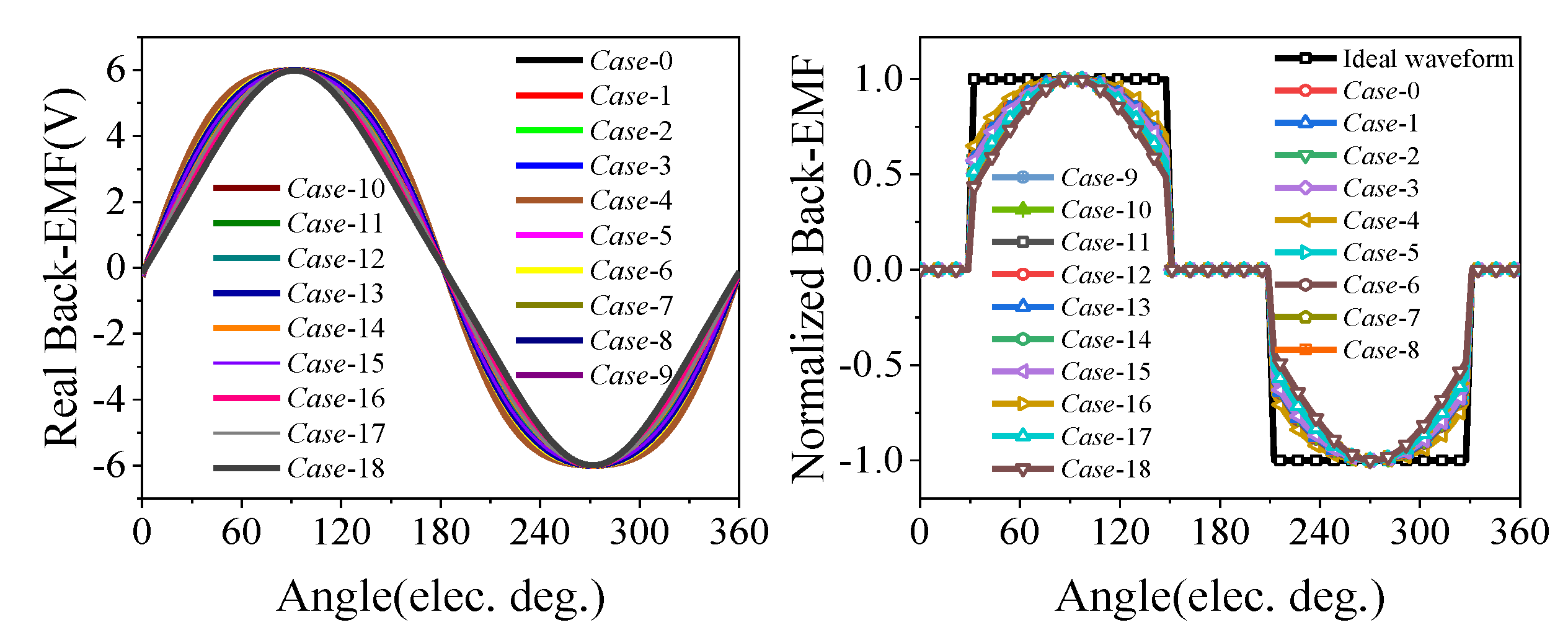
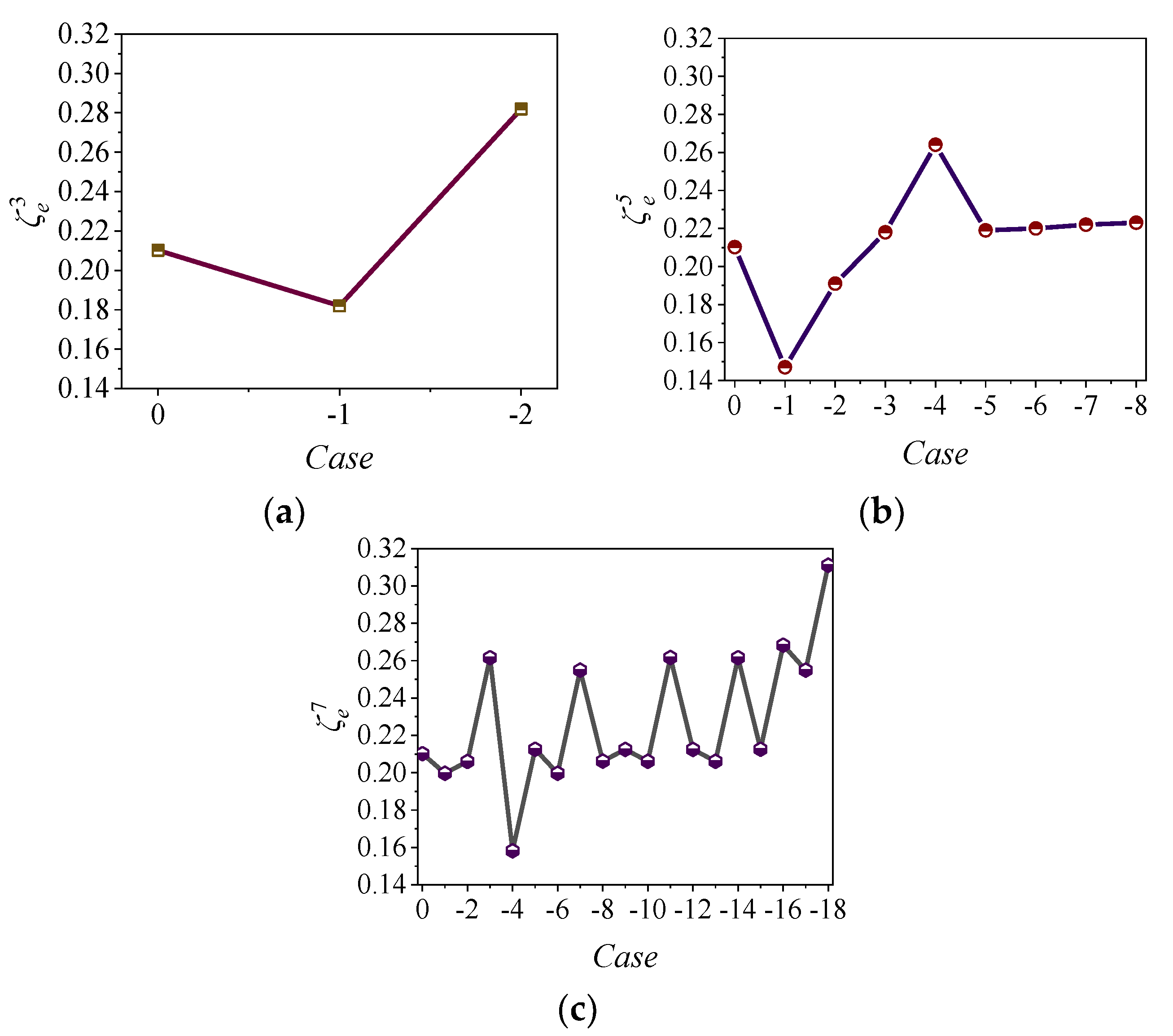
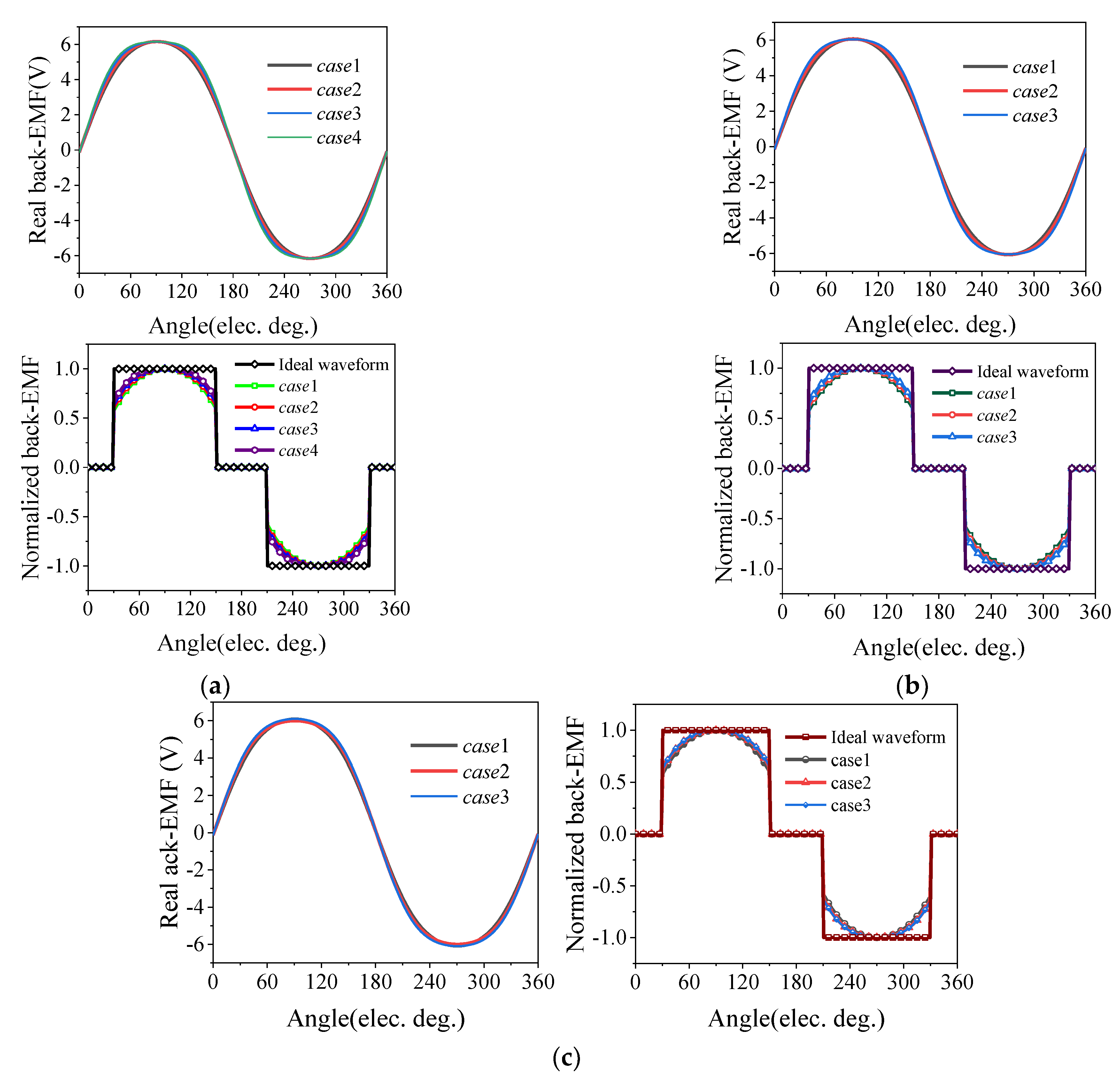
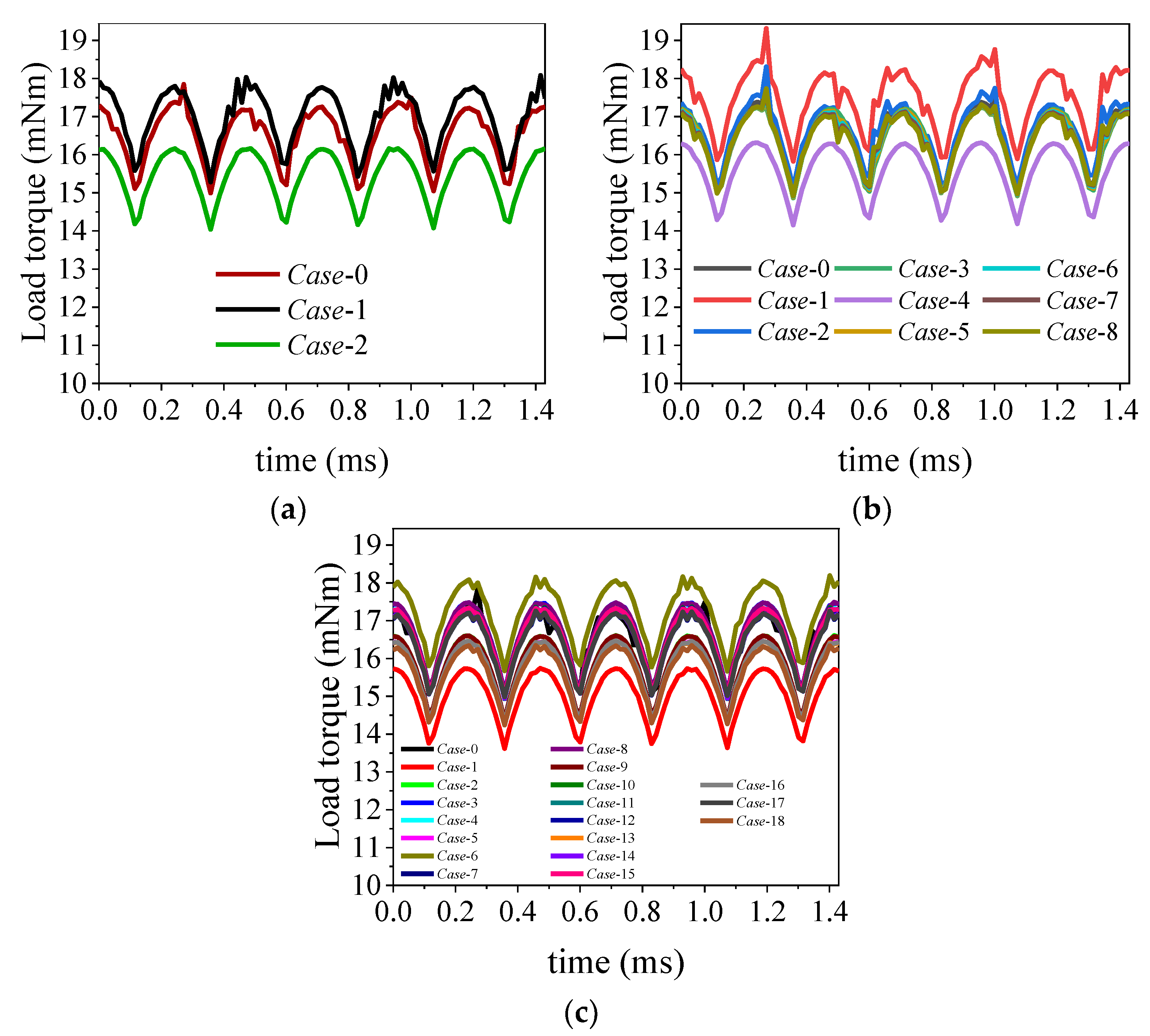
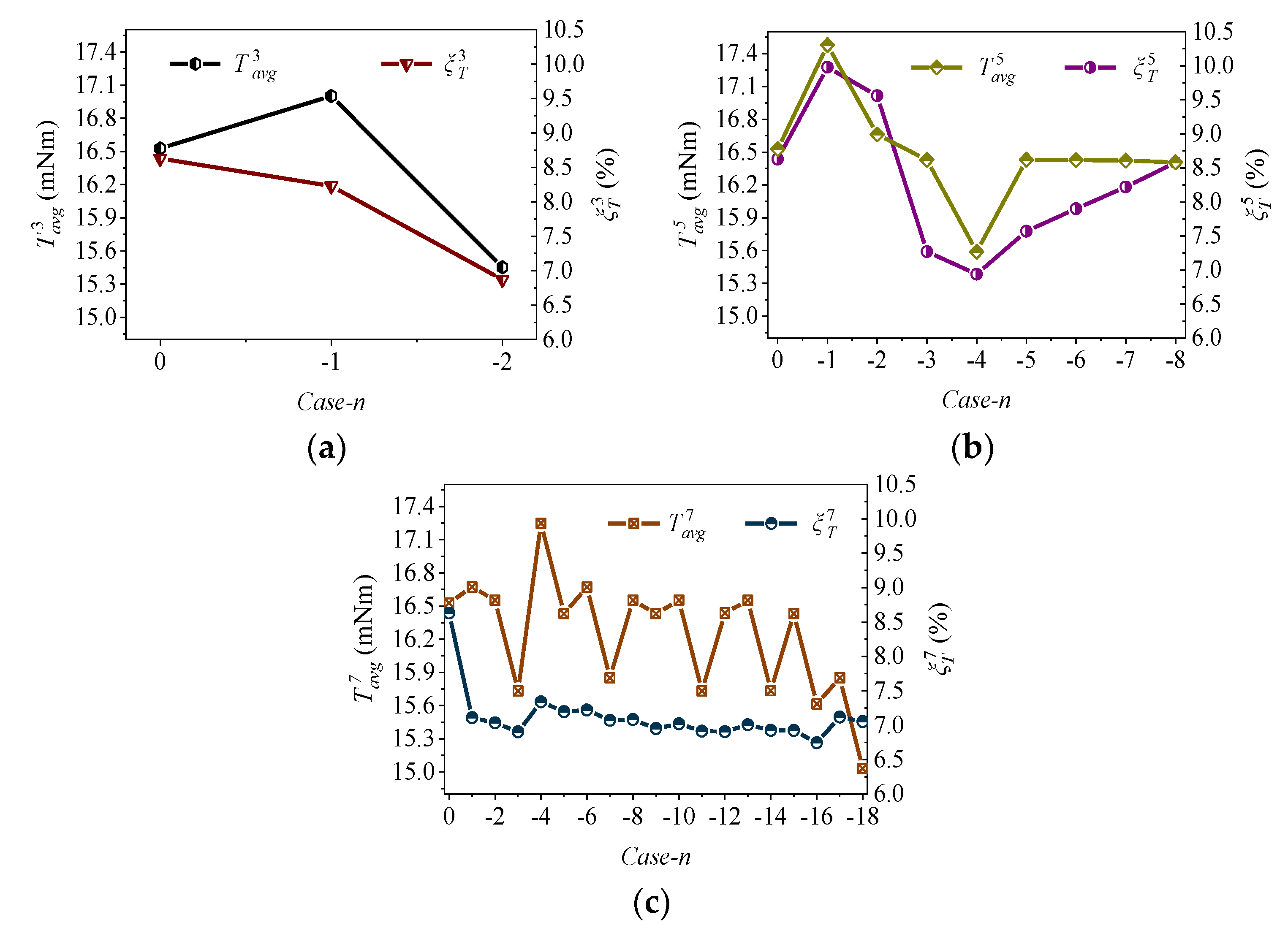
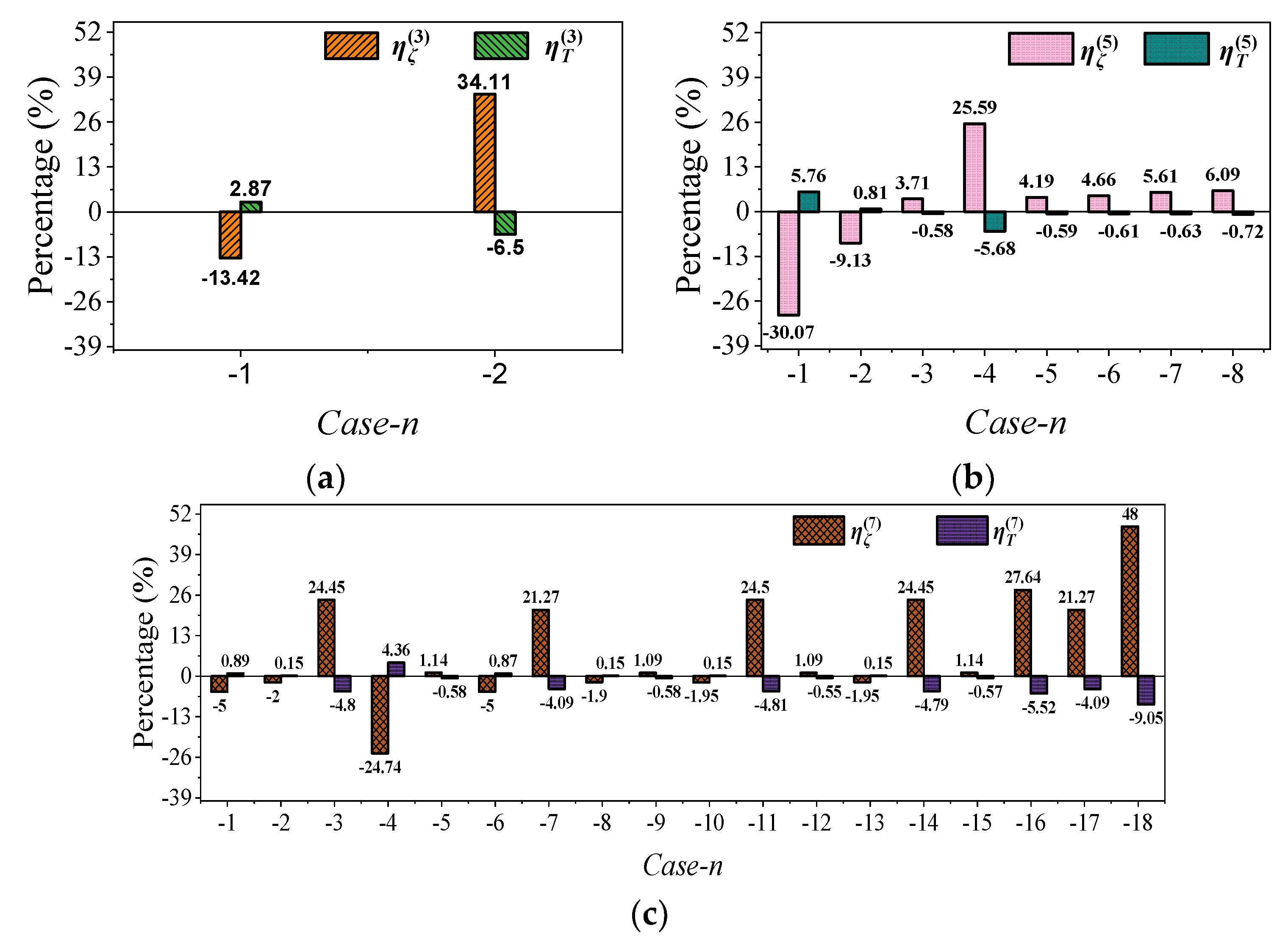
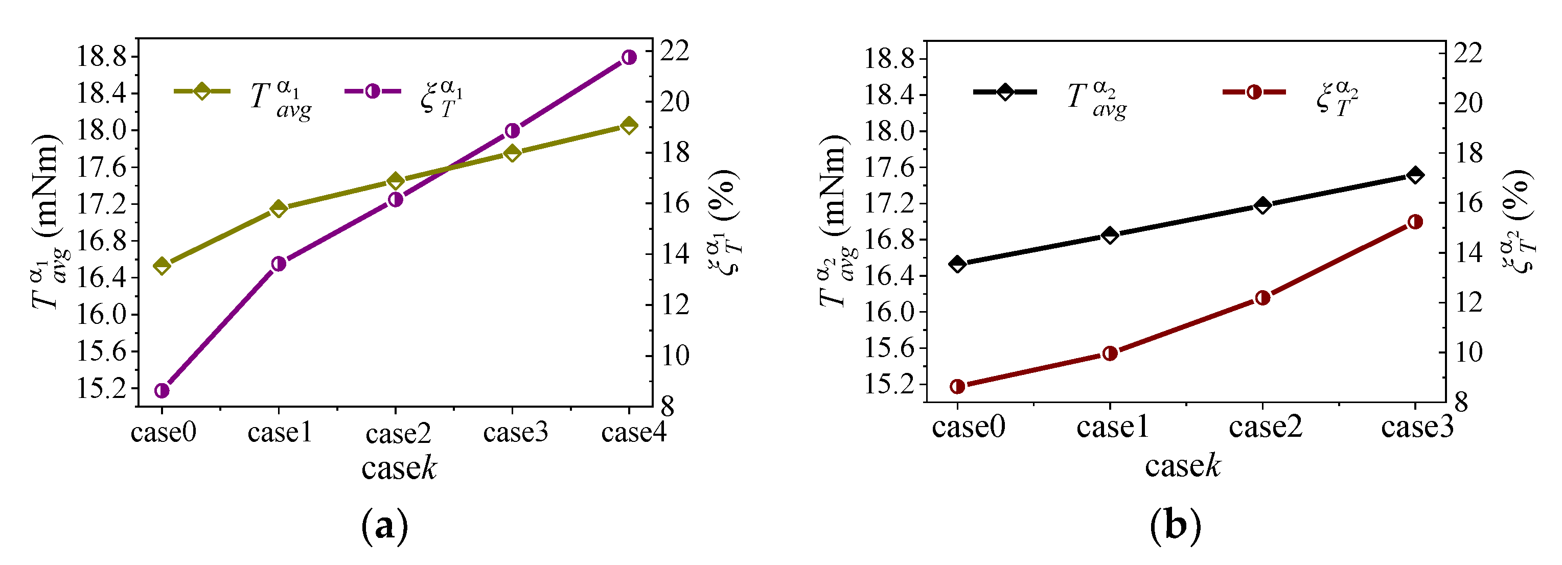
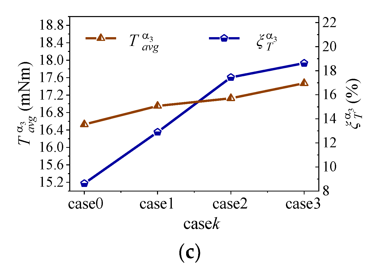
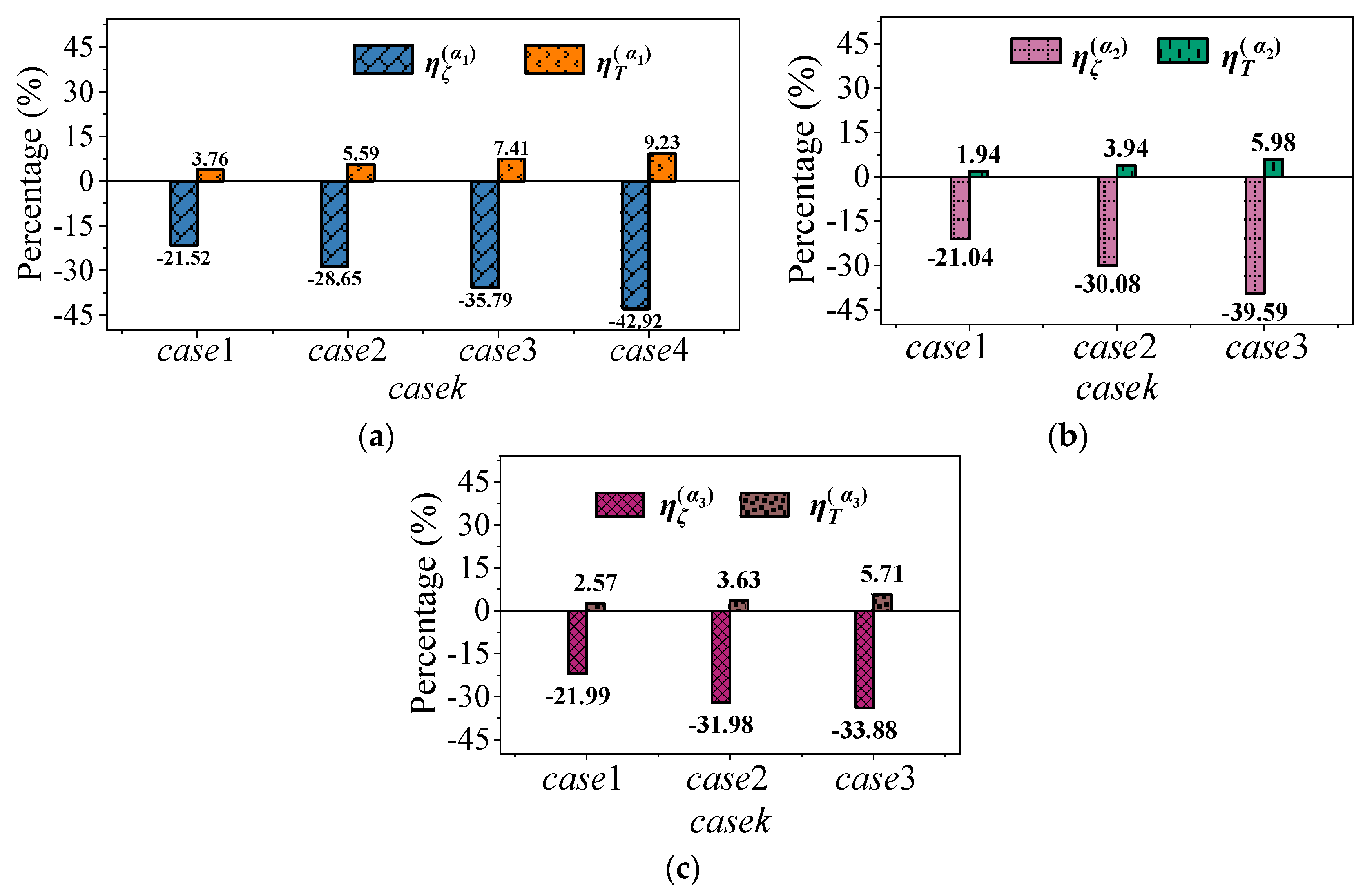
As for PM symmetrical segmentations, the minimum evaluation factor (as shown in Equation (1)) for PMs segmented into three, five, and seven segments, are 0.182, 0.157, and 0.1582, respectively. It should be noted that the smaller the evaluation factor is, the better the trapezoidal degree of the back-EMF. However, the restricted condition for the extracted Cases of PM segment into seven segments is much stricter than the other two segment types. However, it seems that the trapezoidal degree of PMs segmented into five segments present better results than that of PMs segmented into seven segments. Likewise, the load torque is presented in Section 4.1. Considering the different deviation set for different PM symmetrical segmentations, it can be concluded that trapezoidal back-EMF can be easier obtained with the increase in the number of PM symmetrical segments.
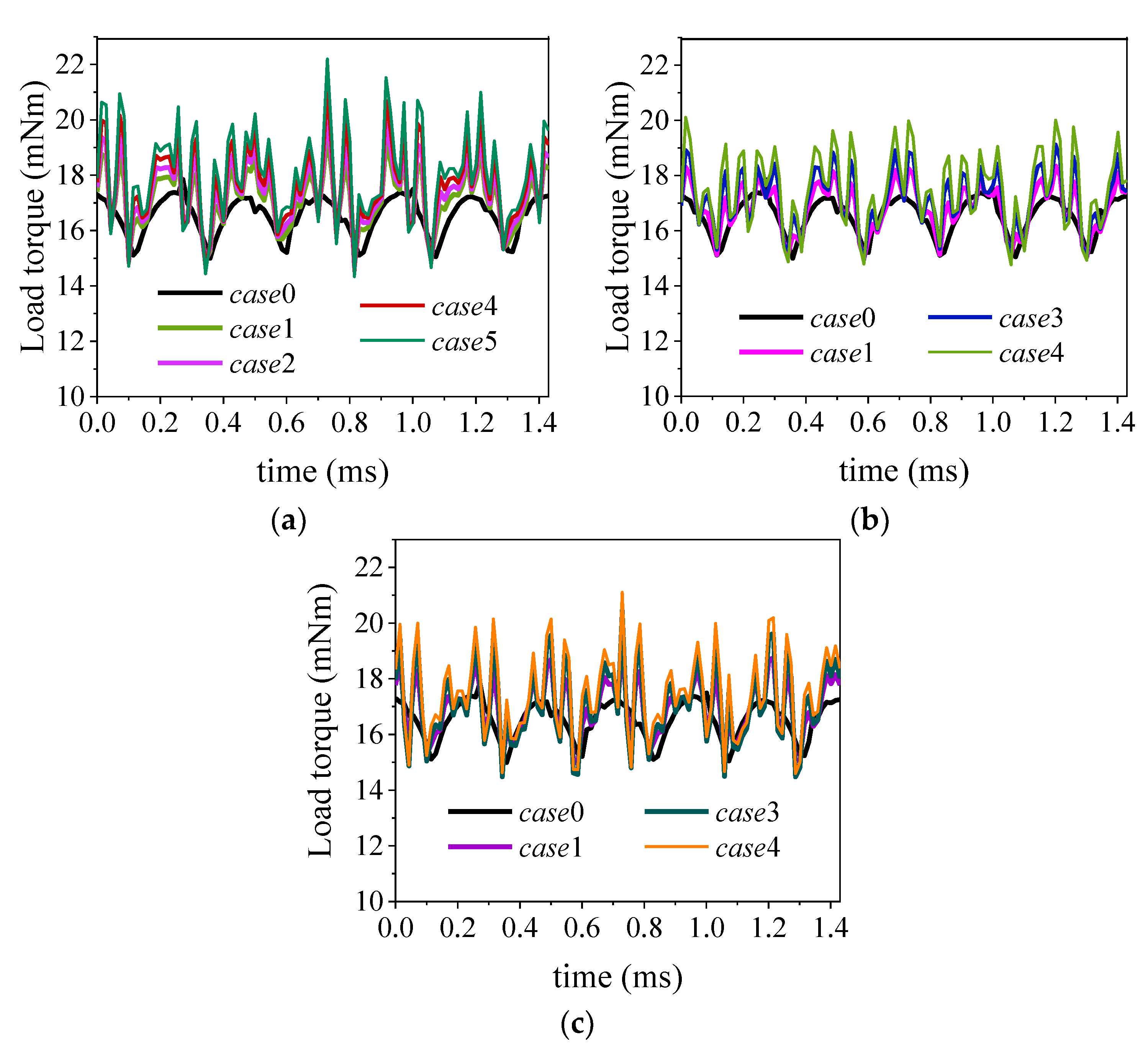
From the comprehensive analysis of the results, it can be found that PM asymmetrical segmentations show better results in back-EMF and load torque performance. In this paper, the load torque for PMs asymmetrical segmentation showed 60% higher than that of PM symmetrical segmentations.
Compared with monoblock PM, segment processing may deteriorate the strength, especially with high rotational speed. However, under the protection of the outer rotor core, the situation of segmented PMs may be well. As for the inner rotor with surface-mounted PMs, well-behaved sleeves or other protective procedures for the PMs should be mounted on the PMs. The effect of PM trapezoidal magnetization on electromagnetic performance may be carried out in future works.
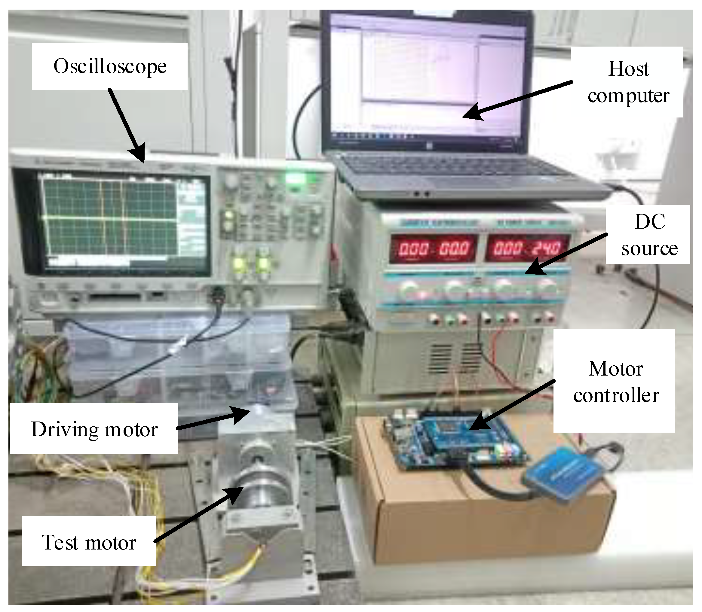
6. Experiment

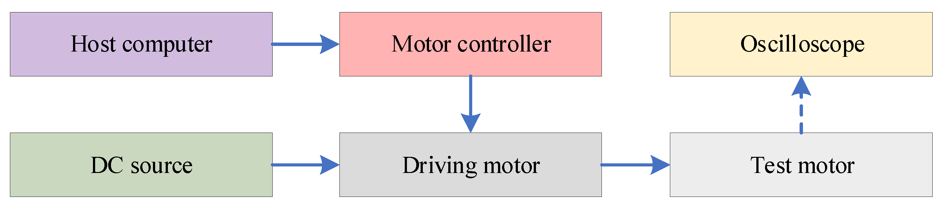
For the sake of validating the viability of the proposed method, and the correctness of the results, two ironless PM BLDC motor prototypes were manufactured and tested. One of the prototypes was without segmentation, while the other was with PMs symmetrically segmented into 3 segments. Additionally, the magnetic field intensity of the segmented sub-PMs corresponds to Case-2 in Table 1. The schematic diagram of the experimental setup and the real test platform are shown in Figure 15 and 
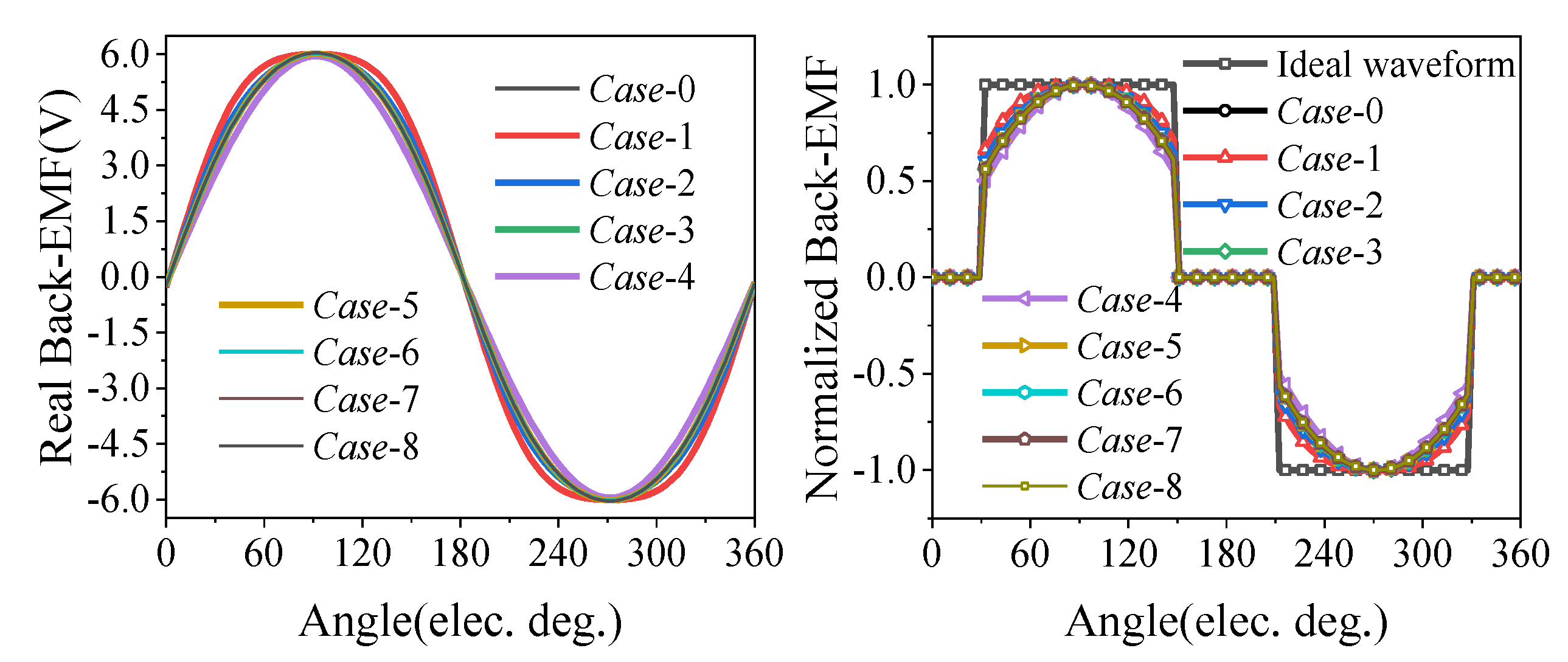
Figure 16, respectively. The DC source was used to provide input power for the driving motor. The host computer controlled the driving motor to rotate at the speed of 3800 rpm, through the motor controller. The test motor and the driving motor were connected through a coupler. Then, the test motor was driven by the driving motor. Considering the symmetry of the three-phase motor, only the no-load back-EMF of phase A was captured by the oscilloscope.
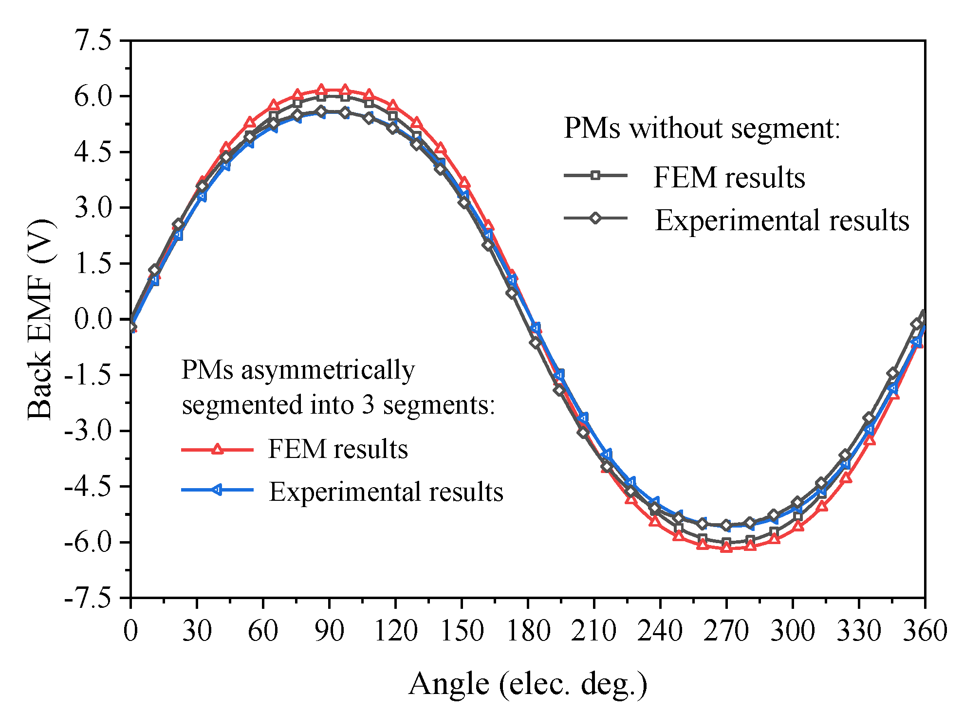
Figure 17 shows the waveforms of the no-load back-EMF of 2-D FEM and experimental results with PMs without segment and PMs asymmetrically segmented into three segments. It can be seen that the back-EMF amplitude of the 2-D FEM results of the PMs segmented into 3 segments is 2.8% higher than that of the PMs without segments. This is mainly because the flux density excited by the PMs segmented into 3 segments is higher than that of the PMs without segments. The fittings degrees between the 2-D FEM and experimental results are 12.9% and 9.7% for the cases of PM without segments and PMs asymmetrically segmented into three segments, respectively. The difference may mainly be due to the deficiency of the PMs’ magnetic field intensity in real motor topology and the ignorance of the axial end effect in 2-D FEM calculation. Overall, the experimental results are in good agreement with those of the FEM method.

7. Conclusions

In this paper, a method of improving the electromagnetic performance of the ironless permanent magnet (PM) BLDC motor in terms of no-load back-EMF and load torque was investigated through PM segmentation with different intensities of magnetizations for the segmented sub-PMs. The results showed that (1) PMs with both symmetrical and asymmetrical segmentations can obtain trapezoidal back-EMF waveforms, which is beneficial for torque improvement; (2) PMs with asymmetrical segmentations present better results on back-EMF and load torque characteristics than those of symmetrical segmentations; (3) specifically, as for the ironless PM BLDC motor investigated in this paper, the load torque for PMs asymmetrically segmented into three segments showed 60% higher than that of PMs symmetrically segment into five and seven segments. Moreover, trapezoidal back-EMF can be easier obtained with the increase in the number of PMs’ symmetrical segments. Finally, two ironless PM BLDC motor prototypes, one with PMs symmetrically segmented into three segments and the other without segments, were manufactured and tested. The experimental and FEM results were compared, and the results showed good agreement.

Author Contributions

Conceptualization, F.Z. and L.Y.; methodology, L.Y.; software, W.F.; validation, F.Z., L.Y., and H.T.; formal analysis, W.F.; investigation, F.Z. and W.F.; resources, L.Y.; data curation, L.Y.; writing—original draft preparation, F.Z. and W.F.; writing—reviewing and editing, L.Y. and H.T.; visualization, W.F. and T.Z.; supervision, L.Y.; project administration, L.Y.; funding acquisition, L.Y. All authors have read and agreed to the published version of the manuscript.

Funding

This research was funded by Qinhuangdao Key Research and Development Program, Grant Number 202004A007.

Institutional Review Board Statement

Not applicable.

Informed Consent Statement

Not applicable.

Data Availability Statement

The data presented in this study are available on request from the corresponding author. The data are not publicly available due to privacy reasons.

Conflicts of Interest

The authors declare no conflict of interest.

Nomenclature

SymbolSpecification
B1Middle sub-PM remanence/T
B2Left or right side sub-PM remanence/T
θCentral angle of the middle PM/°
β1/β2Angle of Left or right side PMs/°
αVariable of the center angle in PM asymmetrical segmentation/°
ζ e 2 k + 1 Evaluation factor for back-EMF trapezoidal degrees with PMs symmetrically segmented into 2k + 1 (k = 1, 2, 3) segments
αnnth harmonics of the normalized back-EMF
βnnth harmonics of the ideal waveform
ξ T 2 k + 1 Torque ripple of PMs symmetrically segment into 2k + 1 (k = 1, 2, 3) segments
T max 2 k + 1 Maximum torque of the PMs symmetrically into 2k + 1 (k = 1, 2, 3) segments / mNm
T min 2 k + 1 Minimum torque of the PMs symmetrically into 2k + 1 (k = 1, 2, 3) segments / mNm
T a v g 2 k + 1 Average torque of the PMs symmetrically into 2k + 1 (k = 1, 2, 3) segments / mNm
η ζ ( 2 k + 1 ) Change percentage of the back-EMF trapezoidal degree with PMs symmetrically segmented into 2k + 1 (k = 1, 2, 3) segments
ζ C a s e n ( 2 k + 1 ) Back-EMF trapezoidal degree evaluation factor at Case-n
ζ 0 Back-EMF trapezoidal degree evaluation factor of PMs without segment
η T ( 2 k + 1 ) Change percentage of load torque with PMs symmetrically segmented into 2k + 1 (k = 1, 2, 3) segments
T C a s e n ( 2 k + 1 ) The load torque at Case-n/mNm
T0Load torque of PMs without segment/mNm
ξ T α n Torque ripple of PMs asymmetrically segment with different angle
T max α n Maximum torque of PMs asymmetrically segment with different angle/mNm
T min α n Minimum torque of PMs asymmetrically segment with different angle/mNm
T a v g α n Average torque of PMs asymmetrically segment with different angle/mNm
T case k ( α n ) Load torque at Case-k with PMs asymmetrical segment/mNm

References

  1. Hwang, M.-H.; Lee, H.-S.; Yang, S.-H.; Cha, H.-R.; Park, S.-J. Electromagnetic field analysis and design of an efficient outer rotor inductor in the low-speed section for driving electric vehicles. Energies 2019, 12, 4615. [Google Scholar] [CrossRef] [Green Version]
  2. Lee, B.-C.; Song, C.-H.; Kim, D.-H.; Kim, K.-C. Study on process derivation and characteristic analysis for BLDC motor design using dual rotor structure with high torque density. Energies 2020, 13, 6745. [Google Scholar] [CrossRef]
  3. Cheng, M.; Sun, L.; Buja, G.; Song, L. Advanced electrical machines and machine-based systems for electric and hybrid vehicles. Energies 2015, 8, 9541–9564. [Google Scholar] [CrossRef] [Green Version]
  4. Anuja, T.; Doss, M. Reduction of cogging torque in surface mounted permanent magnet brushless DC motor by adapting rotor magnetic displacement. Energies 2021, 14, 2861. [Google Scholar] [CrossRef]
  5. Korkosz, M.; Prokop, J.; Pakla, B.; Podskarbi, G.; Bogusz, P. Analysis of open-circuit fault in fault-tolerant BLDC motors with different winding configurations. Energies 2020, 13, 5321. [Google Scholar] [CrossRef]
  6. Yoon, K.-Y.; Baek, S.-W. Robust design optimization with penalty function for electric oil pumps with BLDC motors. Energies 2019, 12, 153. [Google Scholar] [CrossRef] [Green Version]
  7. He, C.; Wu, T. Permanent magnet brushless DC motor and mechanical structure design for the electric impact wrench system. Energies 2018, 11, 1360. [Google Scholar] [CrossRef] [Green Version]
  8. Stephan, D.; Annette, M.; Gerhard, S. Design constraints of small single-phase permanent magnet brushless DC drives for fan applications. IEEE Trans. Ind. Appl. 2015, 51, 3178–3186. [Google Scholar]
  9. Liu, K.; Yin, M.; Hua, W.; Ma, Z.; Lin, M.; Kong, Y. Design and analysis of Halbach ironless flywheel BLDC motor/generators. IEEE Trans. Magn. 2018, 54, 8109305. [Google Scholar] [CrossRef]
  10. Liu, X.; Hu, H.; Zhao, J.; Belahcen, A.; Tang, L.; Yang, L. Analytical solution of the magnetic field and EMF calculation in ironless BLDC motor. IEEE Trans. Magn. 2015, 52, 1–10. [Google Scholar] [CrossRef]
  11. Yang, L.; Zhao, J.; Liu, X.; Haddad, A.; Liang, J.; Hu, H. Effects of manufacturing imperfections on the circulating current in ironless brushless DC motors. IEEE Trans. Ind. Electron. 2018, 66, 338–348. [Google Scholar] [CrossRef]
  12. Xia, K.; Ye, Y.; Ni, J.; Wang, Y.; Xu, P. Model predictive control method of torque ripple reduction for BLDC motor. IEEE Trans. Magn. 2019, 56, 1–6. [Google Scholar] [CrossRef]
  13. Kim, Y.B.; Choi, H.S.; Koh, C.-S.; Shin, P.S. A back EMF optimization of double layered large-scale BLDC motor by using hybrid optimization method. IEEE Trans. Magn. 2011, 47, 998–1001. [Google Scholar] [CrossRef]
  14. Zhang, Q.; Jia, Z.; Cheng, S.; Wang, D. Analysis and calculation of radial electromagnetic force of circular winding brushless DC motor. IEEE Trans. Ind. Electron. 2019, 69, 4338–4349. [Google Scholar] [CrossRef]
  15. Shakouhi, S.M.; Mohamadian, M.; Afjei, E. Torque ripple minimisation control method for a four-phase brushless DC motor with non-ideal back-electromotive force. IET Electr. Power Appl. 2013, 7, 360–368. [Google Scholar] [CrossRef]
  16. Fang, J.; Li, H.; Han, B. Torque ripple reduction in BLDC torque motor with nonideal back EMF. IEEE Trans. Power Electron. 2011, 27, 4630–4637. [Google Scholar] [CrossRef]
  17. Xia, C.; Xiao, Y.; Chen, W.; Shi, T. Torque ripple reduction in brushless DC drives based on reference current optimization using integral variable structure control. IEEE Trans. Ind. Electron. 2013, 61, 738–752. [Google Scholar] [CrossRef]
  18. Chen, X.; Liu, G. Sensorless optimal commutation steady speed control method for a non-ideal back-EMF BLDC motor drive system including buck converter. IEEE Trans. Ind. Electron. 2016, 67, 6147–6157. [Google Scholar] [CrossRef]
  19. Shen, J.; Iwasaki, S. Sensorless control of ultrahigh-speed PM brushless motor using PLL and third harmonic back EMF. IEEE Trans. Ind. Electron. 2006, 53, 421–428. [Google Scholar] [CrossRef]
  20. Li, H.; Zheng, S.; Ren, H. Self-correction of commutation point for high-speed sensorless BLDC motor with low inductance and nonideal back EMF. IEEE Trans. Power Electron. 2016, 32, 642–651. [Google Scholar] [CrossRef]
  21. Song, X.; Han, B.; Zheng, S.; Fang, J. High-precision sensorless drive for high-speed BLDC motors based on the virtual third harmonic back-EMF. IEEE Trans. Power Electron. 2017, 33, 1528–1540. [Google Scholar] [CrossRef]
  22. Lee, A.-C.; Wang, S.; Fan, C.-J. A current index approach to compensate commutation phase error for sensorless brushless DC motors with nonideal back EMF. IEEE Trans. Power Electron. 2015, 31, 4389–4399. [Google Scholar] [CrossRef]
  23. Sheng, T.; Wang, X.; Zhang, J.; Deng, Z. Torque-ripple mitigation for brushless DC machine drive system using one-cycle average torque control. IEEE Trans. Ind. Electron. 2014, 62, 2114–2122. [Google Scholar] [CrossRef]
  24. Li, W.; Fang, J.; Li, H.; Tang, J. Position sensorless control without phase shifter for high-speed BLDC motors with low inductance and nonideal back EMF. IEEE Trans. Power Electron. 2015, 31, 1354–1366. [Google Scholar] [CrossRef]
  25. Zhang, Q.; Cheng, S.; Wang, D.; Jia, Z. Multi-objective design optimization of high-power circular winding brushless DC motor. IEEE Trans. Ind. Electron. 2017, 65, 1740–1750. [Google Scholar] [CrossRef]
  26. Jin, C.S.; Kim, C.M.; Kim, I.J.; Jang, I. Proposed commutation method for performance improvement of brushless DC motor. Energies 2021, 14, 6023. [Google Scholar] [CrossRef]
  27. Yazdani-Asrami, M.; Alipour, M.; Gholamian, S.A. Optimal ECO-design of permanent magnet brushless DC motor using modified tabu search optimizer and finite element analysis. J. Magn. 2015, 20, 161–165. [Google Scholar] [CrossRef] [Green Version]
  28. Unlersen, M.F.; Balci, S.; Aslan, M.F.; Sabanci, K. The speed estimation via BiLSTM-Based network of a BLDC motor drive for fan applications. Arab. J. Sci. Eng. 2021, 1–10. [Google Scholar] [CrossRef]
  29. Yang, L.; Zhao, J.; Liu, X.; Haddad, A.; Liang, J.; Hu, H. Comparative study of three different radial flux ironless BLDC motors. IEEE Access 2018, 6, 64970–64980. [Google Scholar] [CrossRef]
Figure 1. Schematic diagram of the ironless BLDC half model.
Energies 15 00621 g001
Figure 2. Schematic diagram of PMs with two different segment types.
Energies 15 00621 g002
Figure 3. The real and normalized back-EMF waveforms for PMs symmetrically segmented into 3 segments.
Energies 15 00621 g003
Figure 4. The real and normalized back-EMF waveforms for PMs symmetrically segmented into 5 segments.
Energies 15 00621 g004
Figure 5. The real and normalized back-EMF waveforms for PMs symmetrically segmented into 7 segments.
Energies 15 00621 g005
Figure 6. The evaluation factor of back-EMF trapezoidal degree with PMs symmetrically segmented into 2k + 1 segments: (a) k = 1; (b) k = 2; (c) k = 3.
Energies 15 00621 g006
Figure 7. The back-EMF amplitude of different magnetic intensity and α with PMs asymmetrically segmented: (a) α = 1, (b) α = 2, (c) α = 3, (d) α = 4.
Energies 15 00621 g007
Figure 8. The real and normalized back-EMF waveforms with PMs asymmetrically segmented: (a) α = 1°; (b) α = 2°; (c) α = 3°.
Energies 15 00621 g008
Figure 9. The load torque with all the PMs symmetrically segmented into 2k + 1 segments: (a) k = 1; (b) k = 2; (c) k = 3.
Energies 15 00621 g009
Figure 10. The load torque performance with PMs symmetrically segmented into 2k + 1 (k = 1, 2, 3) segments: (a) PMs symmetrically segmented into 3 segments; (b) PMs symmetrically segmented into 5 segments; (c) PMs symmetrically segmented into 7 segments.
Energies 15 00621 g010
Figure 11. The relationship between the back-EMF trapezoidal degree variation with the load torque of PMs symmetrically segmented, compared with those of PMs without segmentation: (a) PMs symmetrically segmented into 3 segments; (b) PMs symmetrically segmented into 5 segments; (c) PMs symmetrically segmented into 7 segments.
Energies 15 00621 g011
Figure 12. The load torque with different cases of PMs asymmetrically segmented: (a) α = 1°; (b) α = 2°; (c) α = 3°.
Energies 15 00621 g012
Figure 13. The load torque performance with PMs asymmetrically segmented: (a) α = 1°; (b) α = 2°; (c) α = 3°.
Energies 15 00621 g013aEnergies 15 00621 g013b
Figure 14. The relationship between the back-EMF trapezoidal degree variation with the load torque of PMs asymmetrically segmented, compared with those of PMs without segmentation: (a) α = 1°; (b) α = 2°; (c) α = 3°.
Energies 15 00621 g014
Figure 15. Schematic diagram of experimental setup.
Energies 15 00621 g015
Figure 16. Experimental test platform.
Energies 15 00621 g016
Figure 17. Simulation and experimental results of PMs without segment and PMs asymmetrically segmented into 3 segments.
Energies 15 00621 g017
Table 1. Magnetic density and back-EMF amplitude with PMs symmetrically segmented into three segments.
B1/TB2/TBack-EMF Amplitude/V
Case-10.91.36.04
Case-21.50.56
Table 2. Magnetic density and back-EMF amplitude with PMs symmetrically segmented into five segments.
B1/TB2/TB3/TBack-EMF Amplitude/V
Case-10.31.51.56.011
Case-20.71.50.56.009
Case-30.91.30.76.017
Case-41.10.91.55.954
Case-51.11.10.96.026
Case-61.30.91.16.034
Case-71.50.71.36.042
Case-81.50.90.55.951
Table 3. Magnetic density and back-EMF amplitude with PMs symmetrically segmented into seven segments.
B1/TB2/TB3/TB4/TBack-EMF Amplitude/V
Case-10.31.51.30.56.007
Case-20.51.11.51.56.005
Case-30.51.31.50.36.006
Case-40.51.50.91.16.004
Case-50.71.31.10.96.003
Case-60.91.11.30.76.002
Case-70.91.30.71.56
Case-80.91.50.70.36
Case-91.10.91.50.56
Case-101.11.10.91.35.999
Case-111.11.30.90.15.999
Case-121.11.50.30.95.998
Case-131.30.91.11.15.998
Case-141.31.30.50.75.996
Case-151.50.71.30.95.997
Case-161.51.10.70.55.995
Case-171.51.30.11.35.994
Case-181.51.50.10.15.993
Table 4. Evaluation factor of the back-EMF trapezoidal degree with α = 1°.
Casecase1/Tcase2/Tcase3/Tcase4/T
B1B2B1B2B1B2B1B2
ζe11.031.230.931.430.831.630.731.83
a = 1°0.1650.150.1350.12
Table 5. Evaluation factor of the back-EMF trapezoidal degree with α = 2°.
Casecase1/Tcase2/Tcase3/T
B1B2B1B2B1B2
ζe11.031.230.931.530.831.83
a = 2°0.1660.1470.127
Table 6. Evaluation factor of the back-EMF trapezoidal degree with α = 3°.
Casecase1/Tcase2/Tcase3/T
B1B2B1B2B1B2
ζe11.031.330.931.730.931.83
a = 2°0.1640.1430.139
Publisher’s Note: MDPI stays neutral with regard to jurisdictional claims in published maps and institutional affiliations.

