
Nonlinear Dynamic Characteristics of Rod Fastening Rotor with Preload Relaxation


Abstract
1. Introduction
2. Rotor Dynamics Modeling of Rod Fastening Rotor System
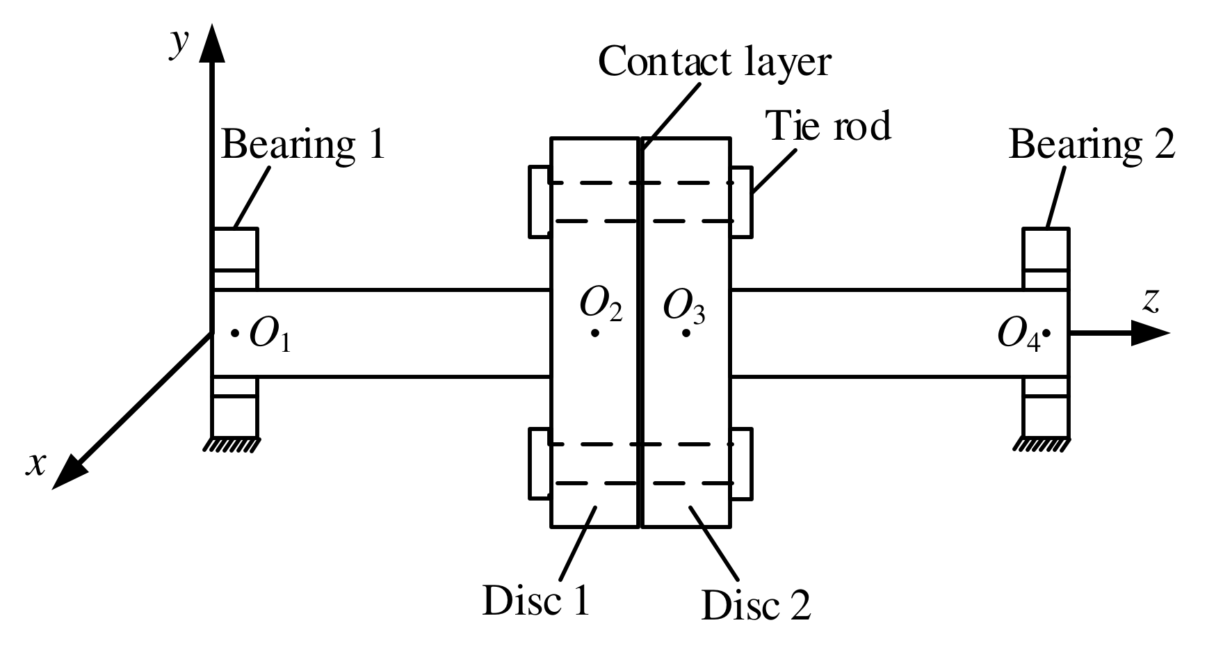
2.1. Structure
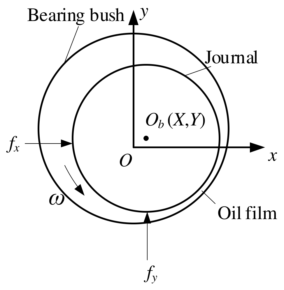
2.2. Oil Film Force of Sliding Bearing
2.3. Bending Stiffness of Disc Contact Layer
2.4. Dynamic Model
2.5. Calculation Results
3. Influence of Uniform Relaxation of Preload on Dynamic Characteristics
4. Influence of Non-Uniform Relaxation of Preload on Dynamic Characteristics
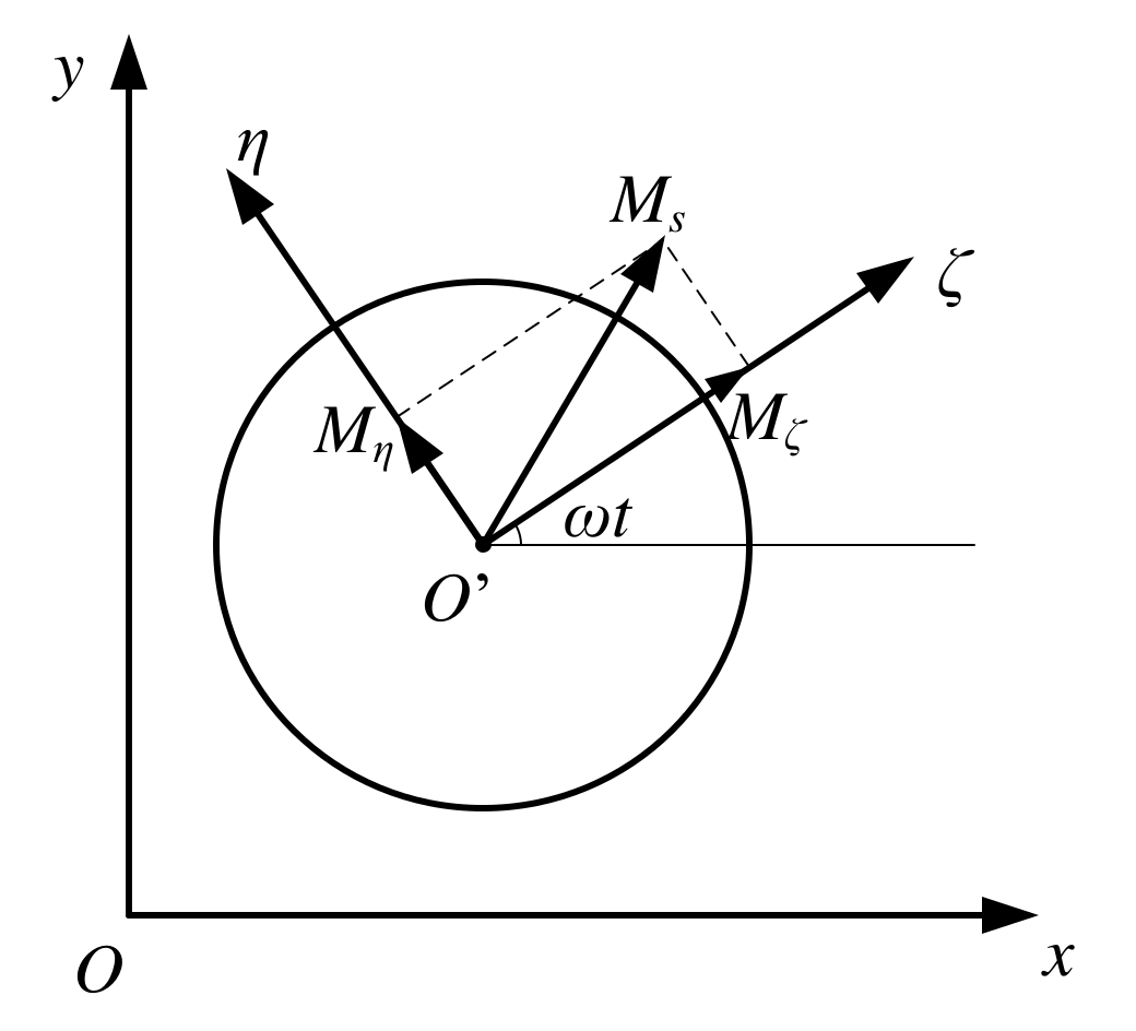
4.1. Additional Moment Model
4.2. Influence of Tie Rod Looseness Rate on Dynamic Characteristics
5. Conclusions
- (1)
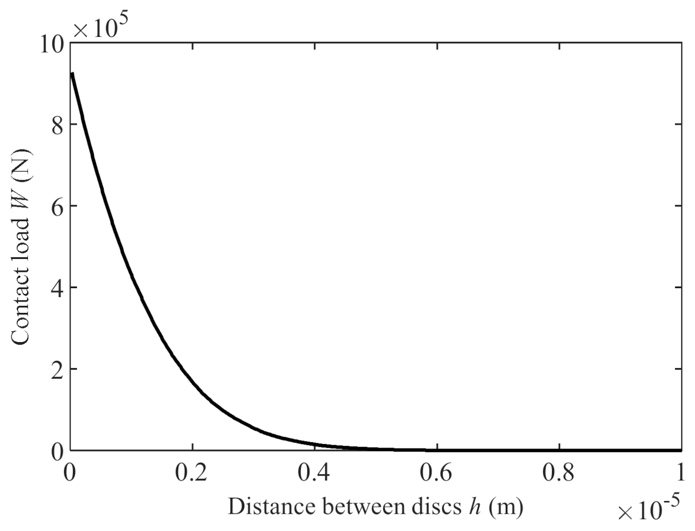
- The contact load of the rod fastening rotor has a nonlinear relationship with the distance between the two disks. With the increase in distance, the preload between the disks decreases, and the decreasing rate decreases gradually. The relationship between contact stiffness and contact load is weakly nonlinear. With the decrease in the preload load, the contact stiffness decreases.
- (2)
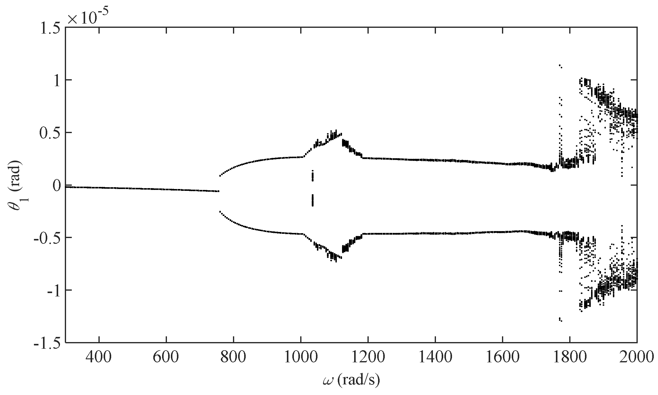
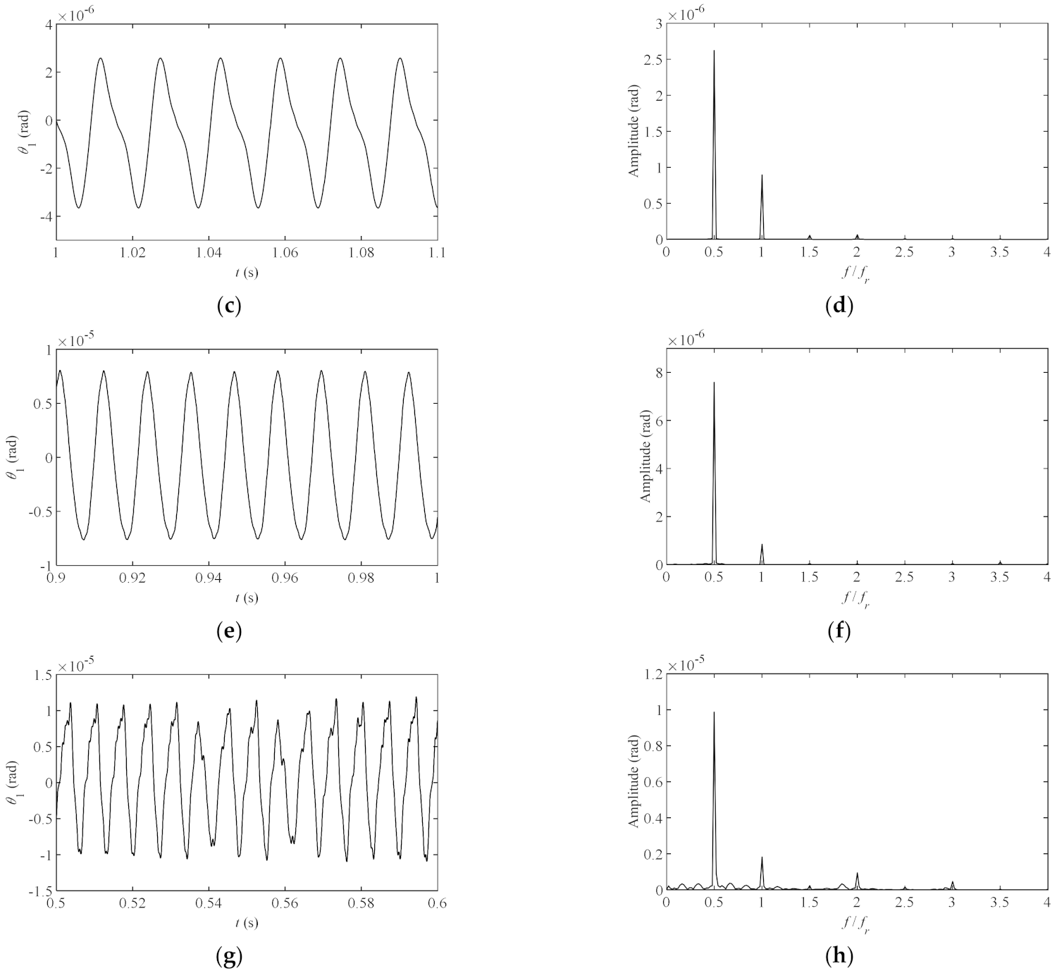
- Affected by nonlinear factors, the rod fastening rotor system has rich dynamic characteristics at different speeds. When the rotation speed is small (under 760 rad/s), it is in a period one motion state, the spectrum diagram has a main component at rotating frequency. As the rotational speed increases (760~1600 rad/s), the system will appear in a period two motion state, and the spectrum diagram has components at rotating frequency and half rotating frequency. At one of the rotational speeds (1000~1200 rad/s), the system is in a weak chaotic state, and the component at half rotating frequency increases. At higher rotational speeds (1600~2000 rad/s), the system is in a chaotic state, many sideband components appear in the frequency spectrum, and the time-domain vibration curve is no longer periodic.
- (3)
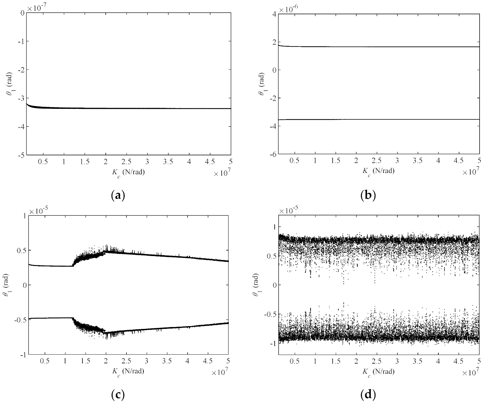
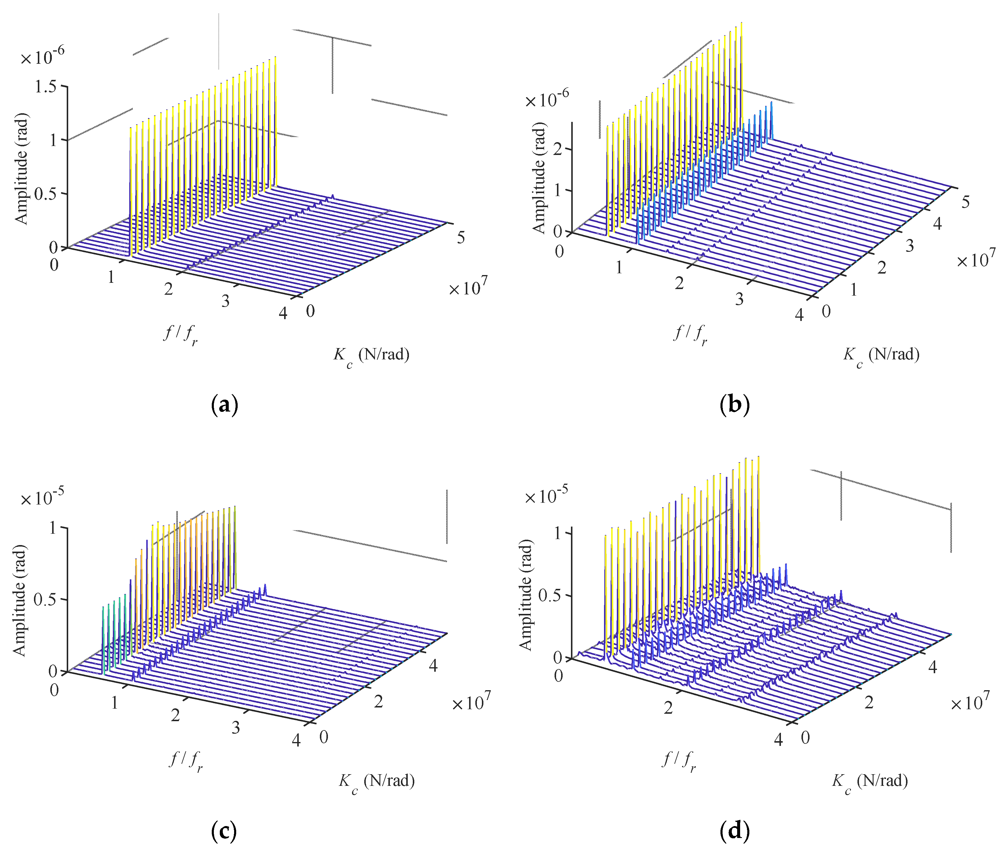
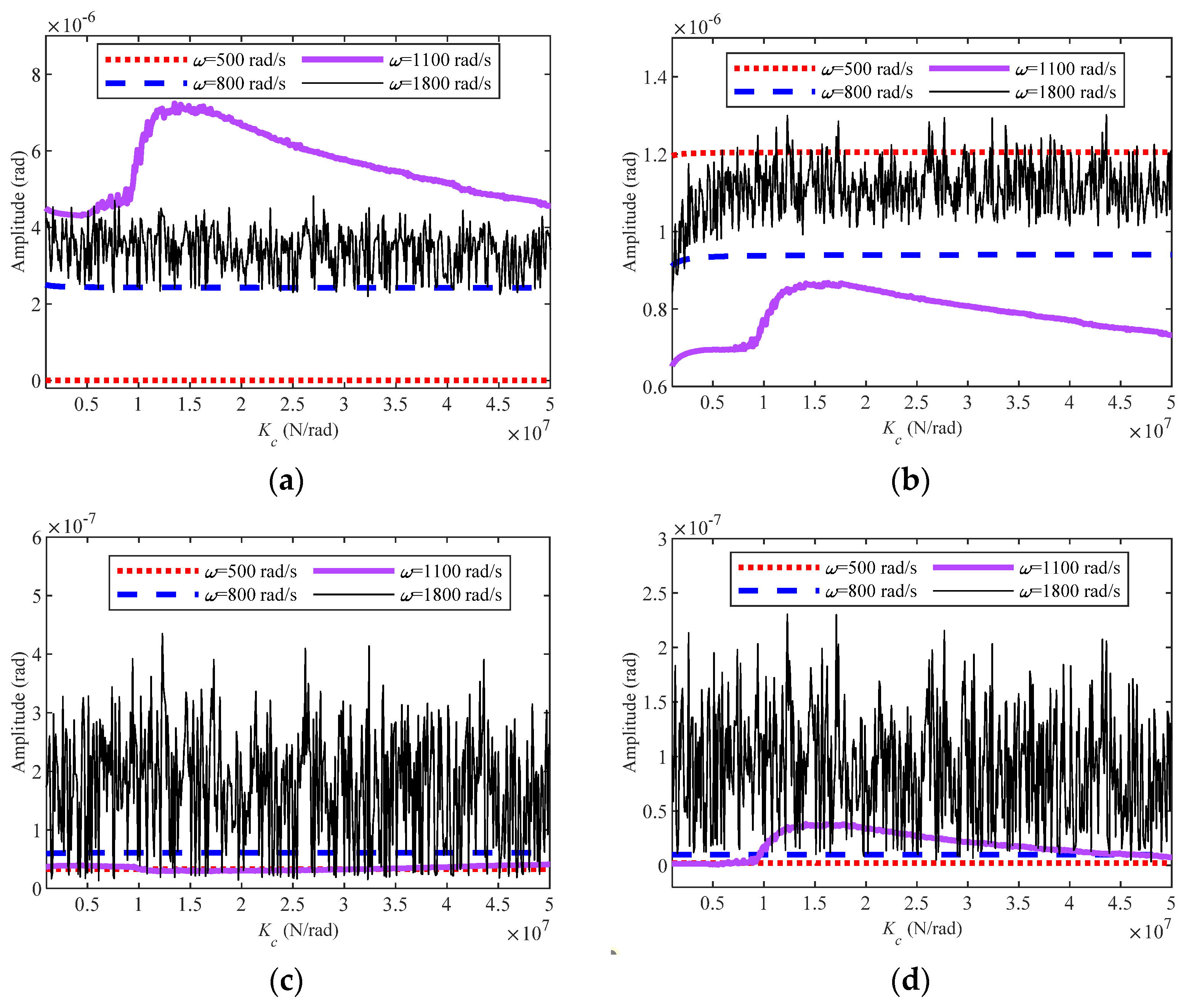
- When the preload of the discs is uniformly relaxed, the influence of the contact stiffness of two discs on dynamic characteristics of the rod fastening rotor system is different at different speeds, which is mainly related to the motion state of the system. When the system is in the stable periodic motion state, such as period one (500 rad/s) and period two (800 rad/s), the vibration displacement, spectrum amplitude and other characteristics are basically not affected by the change of contact stiffness. When the system is in a quasi-periodic or chaotic motion state (1100 rad/s), the system responses show a certain variation law with the change of contact stiffness. When the system is in a strong chaotic state (1800 rad/s), the system responses fluctuate strongly with the change of contact stiffness, and the fluctuation period is not regular.
- (4)
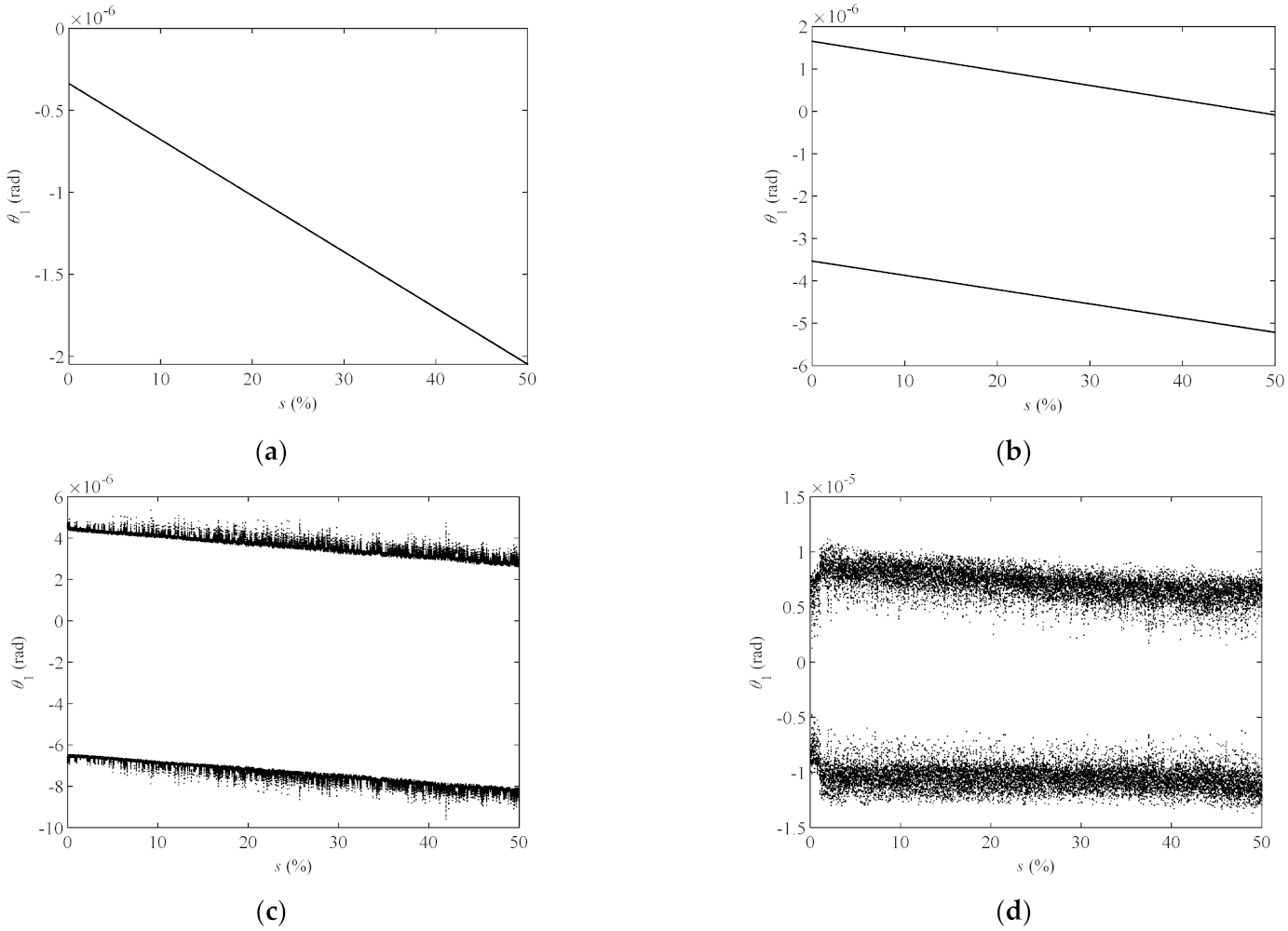
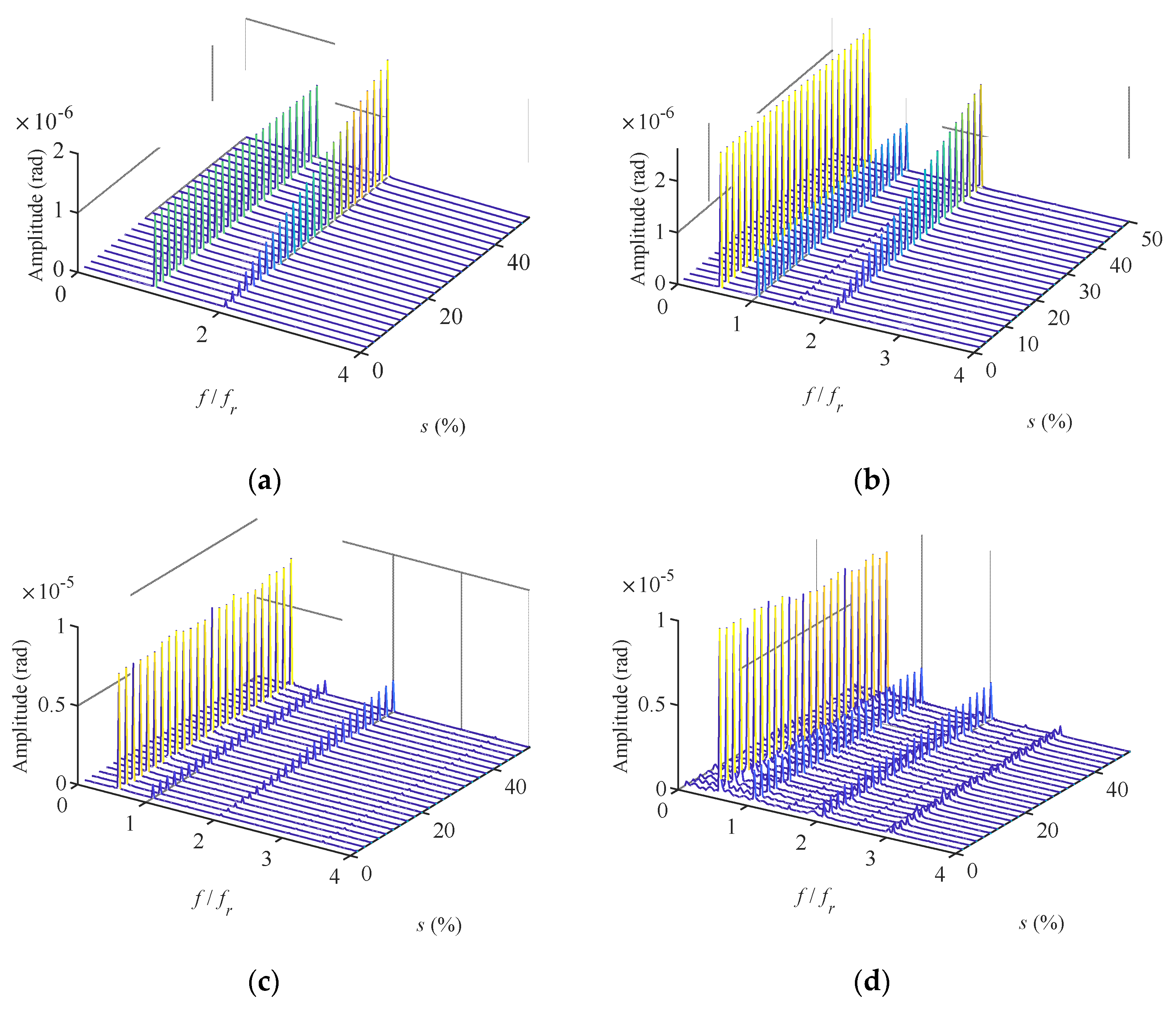
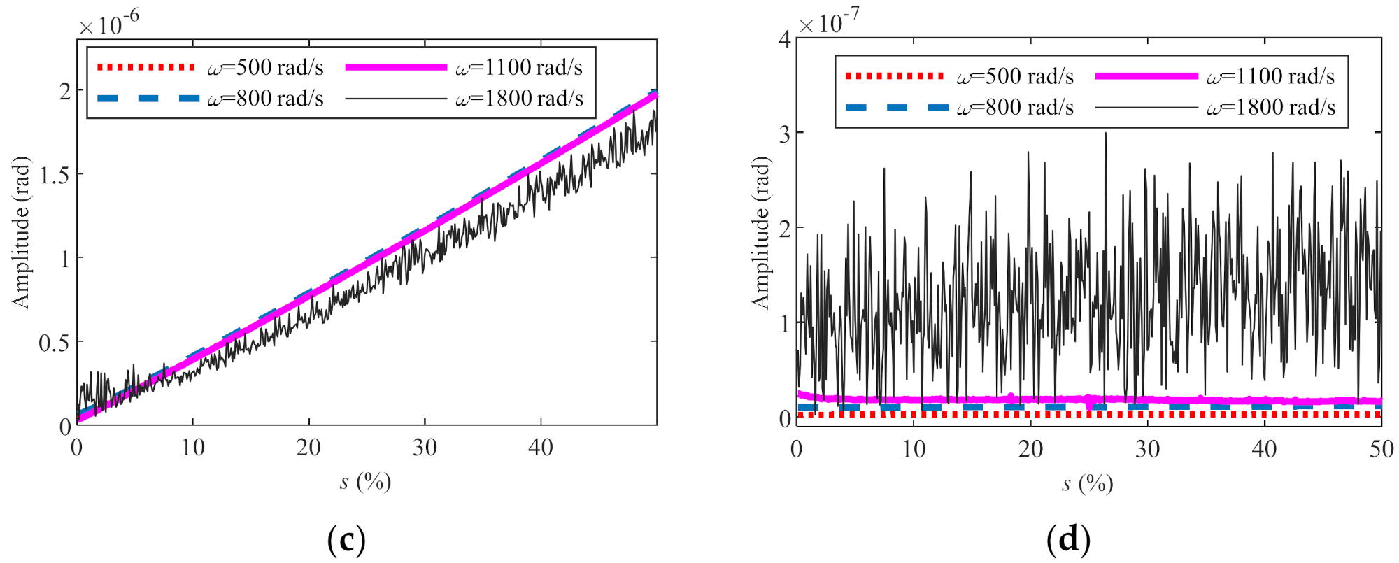
- When the preload of the discs is non-uniformly relaxed and the system is in a stable periodic motion state (500 rad/s and 800 rad/s), along with the increase in the tie rod looseness rate s, the amplitude increases linearly at two times rotating frequency, and remain unchanged at the other frequencies. When the system is in a chaotic motion state (1100 rad/s, 1800 rad/s), the amplitude fluctuates with s. The degree of fluctuation depends on the degree of chaos.
Author Contributions
Funding
Institutional Review Board Statement
Informed Consent Statement
Conflicts of Interest
List of Symbols
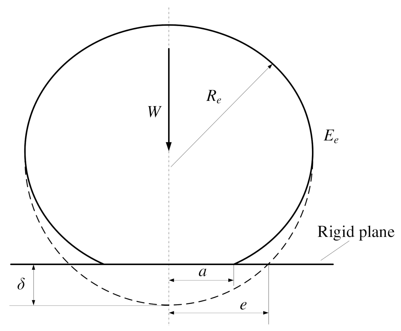
| Ae | Actual contact area between elastomer and rigid plane; |
| a | Radius of contact area between elastomer and rigid plane; |
| c | Sliding bearing clearance; |
| Ee | Equivalent elastic modulus of elastomer; |
| E | shaft segment stiffness; |
| F | External force matrix; |
| Fn | Normal preload; |
| Fs | Relax preload; |
| Fx, Fy | components of nonlinear oil film force of sliding bearing in x direction, y direction; |
| Fxb1, Fyb1, Fxb2, Fyb2 | components of nonlinear oil film force of sliding bearing 1, 2 in x direction, y direction; |
| fx, fy | dimensionless nonlinear oil film force in x direction, y direction; |
| fn | rotating frequency of rotor; |
| G | Gyroscopic matrix; |
| g | gravitational acceleration; |
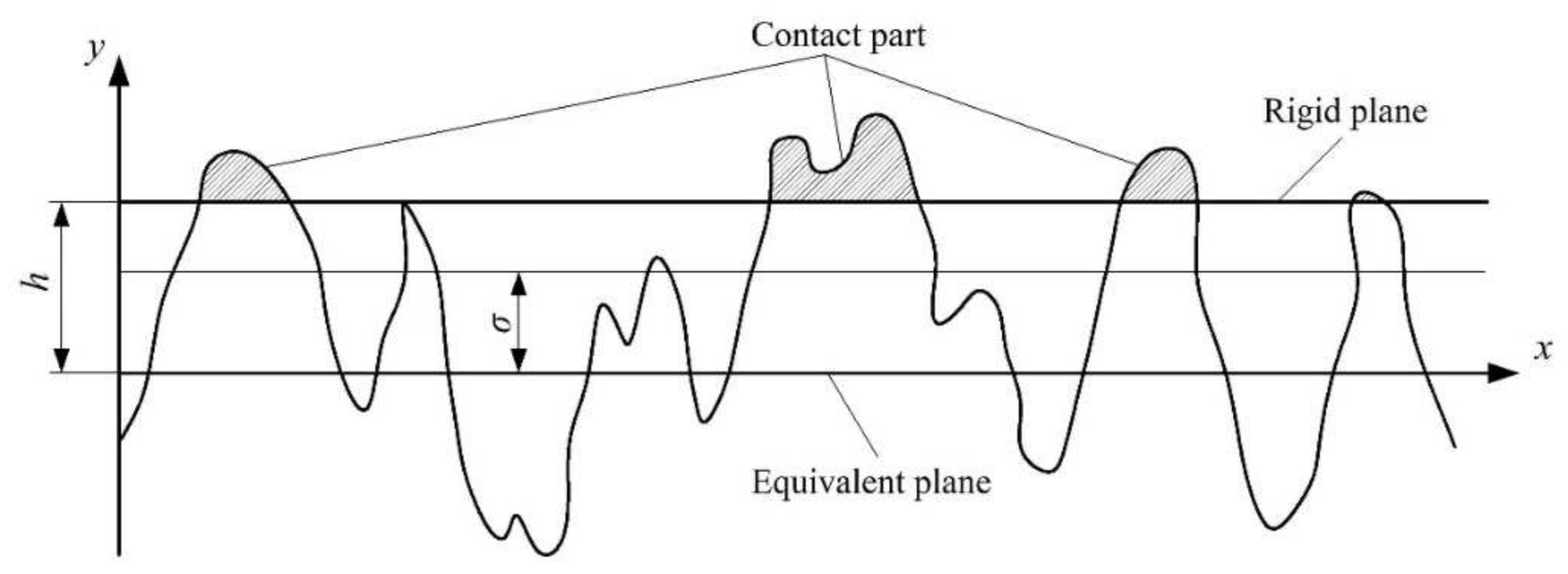
| h | Spacing between rigid plane and rough equivalent plane; |
| Idi, Ipi | Polar and Equatorial moment of inertia of the i-th mass point; |
| Ii | Section moment of inertia of the i-th shaft segment; |
| K | Stiffness matrix; |
| Kc | Equivalent bending stiffness of contact layer; |
| kc | Equivalent elastic coefficient of contact action between two contact planes; |
| Lb | Bearing length; |
| li | Length of the i-th shaft segment; |
| M | Mass matrix; |
| Ms | Additional bending moment; |
| Mx, My | Bending moment in x, y direction; |
| Mxy, Myx | Coupling bending moment in x, y direction; |
| mi | Mass of the i-th mass point; |
| mn | Number of elastic plane micro convex bodies; |
| mP | half of the disk mass; |
| n | Actual number of micro convex bodies in contact; |
| Pc | Contact load per unit area of two contact planes; |
| q | Degree of freedom vector; |
| Rb | Bearing radius; |
| Rd | Disc radius; |
| Re | Equivalent radius of curvature of elastomer; |
| Ri | Tie rod installation radius, Ri = 0.02 m; |
| s | Tie rod looseness rate; |
| t | time of rotor rotation; |
| W | Contact load between elastomer and rigid plane; |
| X, Y | dimensionless displacement of the shaft segment at the sliding bearing position in x direction, y direction; |
| dimensionless velocity in x direction, y direction | |
| xi, yi | Displacement of the i-th mass point in x, y direction; |
| εi, βi | Displacement unbalance and angle unbalance of the i-th mass point; |
| δb | Sommerfeld correction factor; |
| δ | Contact deformation between elastomer and rigid plane; |
| θi, ψi | Angular displacement of the i-th mass point around x, y direction; |
| μ | viscosity of oil; |
| σ | Roughness of contact surface; |
| ρ | Density of micro convex body distribution on rough surface; |
| Φ(z) | Probability density function of elastic plane roughness; |
| ω | rotating speed; |
Appendix A
Appendix B


Appendix C
References
- Rusin, A.; Lukowicz, H.; Lipka, M.; Kosman, W. Analysis of rotor stresses in a gas turbine under unsteady operational conditions. Inz. Chem. I Proces. 2005, 26, 875–887. [Google Scholar]
- Thompson, B.D.; Badgley, R.H. Application of an Advanced Hybrid Rotordynamics Model to the Complete Structure of a Marine Gas Turbine Engine. J. Eng. Gas Turbines Power 1988, 110, 578–584. [Google Scholar] [CrossRef]
- Ehrich, F.F. Observations of Nonlinear Phenomena in Rotordynamics. J. Syst. Des. Dyn. 2008, 2, 641–651. [Google Scholar] [CrossRef][Green Version]
- Almasi, A. The effect of bearings on gas turbine rotor dynamics. Turbomach. Int. 2014, 55, 18. [Google Scholar]
- Kozak, N.; Xu, F.; Rajanna, M.R.; Bravo, L.; Murugan, M.; Ghoshal, A.; Bazilevs, A.; Hsu, M.C. High-Fidelity Finite Element Modeling and Analysis of Adaptive Gas Turbine Stator-Rotor Flow Interaction at Off-Design Conditions. J. Mech. 2020, 36, 595–606. [Google Scholar] [CrossRef]
- Balyakin, V.B.; Ravikozvich, Y.A. Development of Damping Support for a Turbine Pump Assembly of a Cryogenic Fuel Aviation Gas Turbine Engine. J. Frict. Wear 2020, 41, 273–276. [Google Scholar] [CrossRef]
- Brizmer, V.; Kligerman, Y.; Etsion, I. Elastic–plastic spherical contact under combined normal and tangential loading in full stick. Tribol. Lett. 2007, 25, 61–70. [Google Scholar] [CrossRef]
- Kucharski, S.; Starzynski, G. Study of contact of rough surfaces: Modeling and experiment. Wear 2014, 311, 167–179. [Google Scholar] [CrossRef]
- Ciavarella, M.; Greenwood, J.A.; Paggic, M. Inclusion of “interaction” in the Greenwood and Williamson contact theory. Wear 2008, 265, 729–734. [Google Scholar] [CrossRef]
- Pei, L.; Hyun, S.; Molinari, J.F.; Robbins, M.O. Finite element modeling of elasto-plastic contact between rough surfaces. J. Mech. Phys. Solids 2005, 53, 2385–2409. [Google Scholar] [CrossRef]
- Runchao, Z.; Yinghou, J.; Xiuquan, Q.; Sai, Z.; Xianglin, W. Modeling method of gas turbine rotor contact surface based on virtual material layer. J. Harbin Inst. Technol. 2021, 53, 117–123. [Google Scholar]
- Ying, C.; Han, Z.; Yuxi, H. Dynamic Characteristics Analysis of Circumferential Rod Fastening Rotor-Bearing System Considering Contact Stiffness. Power Gener. Technol. 2021, 42, 447–453. [Google Scholar]
- Huiguang, L.; Heng, L.; Lie, Y. Dynamic characteristics of a rod fastening rotor for gas turbine considering contact stiffness. J. Vib. Shock. 2012, 31, 4–8. [Google Scholar]
- Jingjun, W.; Qiang, C. Lateral vibration characteristics of a rod-fastening rotor considering the tightening force and roughness. J. Vib. Shock. 2020, 39, 63–70. [Google Scholar]
- Yeyin, X.; Zhaobo, C.; Yinghou, J. Analysis of rotor contact stiffness based on Persson’s Contact Theory. Noise Vib. Control. 2015, 35, 13–16. [Google Scholar]
- Nanshan, W.; Heng, L.; Yi, L. Normal fractal contact stiffness model among three disks of rod-fastening rotor system with considering friction and the asperities interaction. Ind. Lubr. Tribol. 2021, 73, 652–659. [Google Scholar]
- Liu, Y.; Yuan, Q.; Li, P.; Zhu, G. Modal Analysis for a Rod-Fastened Rotor considering Contact Effect Based on Double Fractal Model. Shock. Vib. 2019, 2019, 4027353. [Google Scholar] [CrossRef]
- Gao, J.; Yuan, Q.; Li, P.; Feng, Z.; Zhang, H.; Lv, Z. Effects of Bending Moments and Pretightening Forces on the Flexural Stiffness of Contact Interfaces in Rod-Fastened Rotors. J. Eng. Gas Turbines Power 2012, 134, 102503. [Google Scholar] [CrossRef]
- Berne, A.L.; Leont’ev, M.K.; Nizametdinov, F.R. Investigation of Bending Stiffness for Flange Joint of GTE Rotor. Mech. Solids 2019, 54, 435–439. [Google Scholar] [CrossRef]
- Schwingshackl, C.W.; Di Maio, D.; Sever, I.; Green, J.S. Modeling and Validation of the Nonlinear Dynamic Behavior of Bolted Flange Joints. J. Eng. Gas Turbines Power 2013, 135, 122504. [Google Scholar] [CrossRef]
- Li, C.; Shuaiying, L.; Zhengwen, Q. Bistable vibration characteristics of disk-rod-fastening rotor with squeeze film dumper. J. Aerosp. Power 2013, 28, 2044–2049. [Google Scholar]
- Liu, Y.; Liu, H.; Wang, X.; Jing, M. Nonlinear dynamic characteristics of a three-dimensional rod-fastening rotor bearing system. J. Mech. Eng. Sci. 2015, 229, 882–894. [Google Scholar] [CrossRef]
- He, Q.; Wang, A.; Chen, Z.; Yang, J. The Axial Vibration Characteristics of Rod Fastening Rotor Considered Contact Normal Stiffness. Chin. Mech. Eng. 2018, 29, 2954–2958. [Google Scholar]
- Hu, L.; Liu, Y.; Zhao, L.; Zhou, C. Nonlinear Dynamic Response Characteristics of a Rod Fastening Rotor with Rub-Impact Faults. Noise Vib. Control. 2016, 36, 11–14+20. [Google Scholar]
- Hu, L.; Liu, Y.; Zhao, L.; Zhou, C. Nonlinear dynamic response of a rub-impact rod fastening rotor considering nonlinear contact characteristic. Arch. Appl. Mech. 2016, 86, 1869–1886. [Google Scholar] [CrossRef]
- Hu, L.; Liu, Y.; Teng, W.; Zhou, C. Nonlinear coupled dynamics of a rod fastening rotor under rub-impact and initial permanent deflection. Energies 2016, 9, 883. [Google Scholar] [CrossRef]
- Li, A.; Li, Z.; Chuandi, Z. Nonlinear Dynamic Characteristics of a Rod Rotor with Rub-Impact Faults Under Bending-Torsion Coupling. J. Chin. Soc. Power Eng. 2020, 40, 213–219. [Google Scholar]
- Wang, N.; Liu, H.; Liu, Y.; Wang, Q.; Qi, S.; Xu, Z. Effect of a transverse crack on the dynamic behaviours of a 3D rod-fastening rotor bearing system. Ind. Lubr. Tribol. 2021, 73, 221–229. [Google Scholar] [CrossRef]
- Wang, N.; Liu, H.; Wang, Q.; Qi, S.; Liu, Y. Experimental dynamic analysis of rod-fastening rotor bearing system with a transverse crack. Ind. Lubr. Tribol. 2021, 73, 422–429. [Google Scholar] [CrossRef]
- Di, H.; Meiru, Z.; Keqi, S. Dynamic analysis on the rod-fastening rotor system with pedestal looseness based on the Newmark method. J. Mach. Des. 2021, 38, 115–126. [Google Scholar]
- Hei, D.; Lu, Y.; Zhang, Y.; Lu, Z.; Gupta, P.; Müller, N. Nonlinear dynamic behaviors of a rod fastening rotor supported by fixed–tilting pad journal bearings. Chaos Solit. Fractals 2014, 69, 129–150. [Google Scholar] [CrossRef]
- Qi, D.; Qi, Y.; Pu, L. Nonlinear Dynamic Characteristics of a Rod- Fastened Rotor System. J. Xi’an Jiaotong Univ. 2019, 53, 43–51. [Google Scholar]
- Xu, H.; Yang, L.; Xu, T.; Wu, Y. Effect of Detuning of Clamping Force of Tie Rods on Dynamic Performance of Rod-Fastened Jeffcott Rotor. Math. Probl. Eng. 2021, 2021, 6645978. [Google Scholar] [CrossRef]
- Haoliang, X.; Lihua, Y.; Tengfei, X. Dynamic Analysis of the Rod-Fastened Rotor Considering theCharacteristics of Circumferential Tie Rods. Appl. Sci. 2021, 11, 3829. [Google Scholar]
- Youfeng, Z.; Xinhua, L.; Qiang, W.; Zibo, W.; Hongyu, Z. Nonlinear modeling and simulation of flywheel energy storage rotor system with looseness and rub-impact coupling hitch. Int. J. Nonlinear Sci. Numer. Simul. 2020. [Google Scholar] [CrossRef]
- Peng, H. Analysis of Dynamic Characteristics of Distributed Rod Fastening Rotor. Ph.D. Thesis, Harbin Institute of Technology, Harbin, China, 2009. [Google Scholar]
- Linsheng, S. Power Plant Metal Material; China Electric Power Press: Beijing, China, 2006. [Google Scholar]
- Wu, X.; Jiao, Y.; Chen, Z.; Ma, W. Establishment of a contact stiffness matrix and its effect on the dynamic behavior of rod-fastening rotor bearing system. Arch. Appl. Mech. 2021, 91, 3247–3271. [Google Scholar] [CrossRef]


| Σ (μm) | Re (μm) | ρ (/m2) | R (mm) |
|---|---|---|---|
| 2.01 | 95 | 5.62 × 10⁷ | 40 |
| Parameter | Value | Parameter | Value |
|---|---|---|---|
| m1, m4 (kg) | 0.0652 | Id2, Id3 (kg·m2) | 2.48 × 10⁻⁴ |
| m2, m3 (kg) | 0.592 | Ip1, Ip4 (kg·m2) | 4.31 × 10⁻⁶ |
| ε2, ε3 (mm) | 0.008 | l1, l4 (m) | 0.3 |
| Rb (mm) | 11.5 | E (Pa) | 2.1 × 10¹¹ |
| Lb (mm) | 20 | β2, β3 (rad) | 1 × 10⁻⁵ |
| c (mm) | 0.11 | g (m/s2) | 9.81 |
| Id1, Id4 (kg·m2) | 4.33 × 10⁻⁶ | μ (Pa·s) | 0.018 |
Publisher’s Note: MDPI stays neutral with regard to jurisdictional claims in published maps and institutional affiliations. |
© 2022 by the authors. Licensee MDPI, Basel, Switzerland. This article is an open access article distributed under the terms and conditions of the Creative Commons Attribution (CC BY) license (https://creativecommons.org/licenses/by/4.0/).
Share and Cite
Zhao, L.; Zhang, H.; Shen, P.; Liu, Y. Nonlinear Dynamic Characteristics of Rod Fastening Rotor with Preload Relaxation. Energies 2022, 15, 1052. https://doi.org/10.3390/en15031052
Zhao L, Zhang H, Shen P, Liu Y. Nonlinear Dynamic Characteristics of Rod Fastening Rotor with Preload Relaxation. Energies. 2022; 15(3):1052. https://doi.org/10.3390/en15031052
Chicago/Turabian StyleZhao, Li, Haosui Zhang, Peng Shen, and Yibing Liu. 2022. "Nonlinear Dynamic Characteristics of Rod Fastening Rotor with Preload Relaxation" Energies 15, no. 3: 1052. https://doi.org/10.3390/en15031052
APA StyleZhao, L., Zhang, H., Shen, P., & Liu, Y. (2022). Nonlinear Dynamic Characteristics of Rod Fastening Rotor with Preload Relaxation. Energies, 15(3), 1052. https://doi.org/10.3390/en15031052