Abstract
Gas condensate reservoirs exhibit complex thermodynamic behaviors when the reservoir pressure is below the dew point pressure, leading to a condensate bank being created inside the reservoir, including gas and oil condensation. Due to natural fractures and multi-phase flows in fractured gas condensate reservoirs, there can be an erroneous interpretation of pressure-transient data using traditional multi-phase models or a fractured model alone. This paper establishes an analytical model for a well test analysis in a gas condensate reservoir with natural fractures. A three-region composite model was employed to characterize the multi-phase flow of retrograde condensation, and the fractured formation was described by a dual-porosity medium. In the first region, both the gas and condensate phases were mobile. In the second region, the gas was mobile whereas the condensates were immobile. In the third region, the only moving phase was the gas phase. The analytical solution was solved by a Laplace transformation to change the partial differential equations to ordinary differential equations. The Stehfest numerical inversion technique was then used to convert the solution of the proposed model into real space. Subsequently, the type curve was obtained and six flow regimes were determined. The influence of several factors on the pressure performance were studied by a sensitivity analysis. Finally, the accuracy of the model was verified by a case study. The model analysis results were in good agreement with the actual formation data. The proposed model provides a few insights toward the production behavior of fractured gas condensate reservoirs, and can be used to evaluate the productivity of such reservoirs.
1. Introduction
A condensate gas reservoir is known as a special type of reservoir with complex flow mechanisms [1]. The exploitation of such reservoirs not only yields natural gas from the formation, but also crude oil [2,3]. Due to the characteristics of condensate gas, condensate precipitates with a decrease in the formation pressure, resulting in a continuous increase in the oil phase content [4]. The gradual increase in the condensate saturation and the continuous expansion of the two-phase flow area harm the effective permeability of the gas phase and reduce the productivity of gas wells [5]. The flow pattern of a condensate gas reservoir depends on the condensate zone near the well. It is very important to understand the effect of condensate accumulation on the productivity and composition of the liquid-phase components as well as on the optimization of production strategies, the reduction in condensate zone influences, and improvements to the ultimate recovery [6,7]. The key factor controlling the productivity of a condensate gas reservoir is relative permeability, which directly affects condensate accumulation [8]. The condensate zone not only reduces the permeability between the gas and liquid phase, but also changes the phase components of the reservoir fluid, thus reshaping the reservoir fluid phase diagram and changing the fluid characteristics. There are significant differences between the early pressure dynamics affected by a variable well reservoir and the typical curve of a fixed well reservoir in their morphology. Increasing the qualitative understanding of the dynamic characteristics of a variable well reservoir is helpful to correctly fit the early data and improve the reliability of the interpretation. However, the existing gas condensate test models do not consider the influence of natural fractures. The existence of natural fractures is one of the major difficulties in oil and gas exploration.
For the first time, Martin gave theoretical proof of the Perrine–Martin method, which was a new way to study the well test method of a condensate gas reservoir [9]. The single-phase model is used to study the complex two-phase seepage problem, which greatly supplements the well test theory of a condensate gas reservoir. Fussell proposed that the well test analysis method of single-phase flow model could be fully applied to the analysis and study of multiphase system when the total flow and total comprehensive compression coefficient of the multiphase system were used to replace the corresponding parameters of the single-phase system [10]. Søgnesand demonstrated that retrograde condensate had a serious impact on the productivity of vertically fractured condensate gas wells [11]. He proposed a method to calculate condensate clogging using a modified skin factor. Xiong Yu studied an unstable model of a condensate gas reservoir, used condensate oil–gas two-phase pseudo-pressure, and modified it on the basis of a single-phase gas well analysis [12]. Gringarten introduced a capillary force effect into a numerical simulation and found that condensate oil in the near-well area was not as highly accumulated as conventionally understood, but its saturation was lower than that in other areas [8]. Therefore, the flow dynamics of condensate gas reservoirs could be described by a four-zone model. Based on the theory of a multi-phase flow and the mechanics of porous media, Li Xiangfang proposed a modified model based on a three-zone model considering the transition zone between the flow patterns of a multi-phase flow and the stripping effect of the fluid velocity [13]. The modified mechanism model showed that there were transition zones between each zone and the flow pattern, which is important for the analysis of an unstable pressure response. This means that whether the pressure falls or the pressure recovers, the oil and gas distribution in the reservoir presents a multi-zone and multi-phase state. However, the extent of the transition zone and how it affects the calculation of the reservoir parameter distribution require further studies. Kool et al. proposed a method and procedure for a PVT analysis that could be used to analyze the composition of condensate gas reservoirs [14]. Clarkson et al. proposed a new method for predicting condensate gas well productivity by comparing an analytical method, a semi-analytical method, and an empirical formula [15]. Zeng and Zhao proposed a semi-analytical method to solve the equation of a pressure-transient analysis for a non-Darcy flow [16]. In addition, Sureshjani et al. performed a semi-analytical simulation of a pressure-transient analysis of condensate gas reservoirs using a modified material balance equation [17]. Behmanesh et al. studied semi-analytic flow models for a pressure-transient analysis and a rate-transient analysis [18]. Wang proposed a semi-analytical model to characterize the bottom-hole pressure behavior of a two-phase flow by coupling the dynamic flow in the wellbore, fractures, and reservoir [19,20]. Wei proposed a novel and simple hydraulic fracturing well test analysis model suitable for multi-well interference in double-porosity gas reservoirs, which was significantly shorter in the calculation time and workload than the existing methods [21,22]. To sum up, most of the current research on fractures related to condensate gas reservoirs relates to a fracturing well and the solution methods are either a numerical method or a semi-analytical method, which is relatively complex. At present, there is no analytical method for condensate gas reservoirs with natural fractures.
In order to interpret the pressure-transient data in a fractured gas condensate reservoir, it was necessary to analyze and study the pressure-transient analysis method of a phase change condensate gas well. A well test analysis method suitable for most phase change gas wells was obtained. We improved the characterization and solution of the two-phase and natural fracture effect, characterizing the mobility ratio, cross-flow coefficient, storage capacity ratio, and composite radius. We discuss how these phenomena can influence bottom-hole pressure responses. Finally, the proposed methodology was successfully applied to the Bohai Oilfield in China to evaluate the performance of a fractured gas condensate reservoir.
2. Methodology
2.1. Physical Model
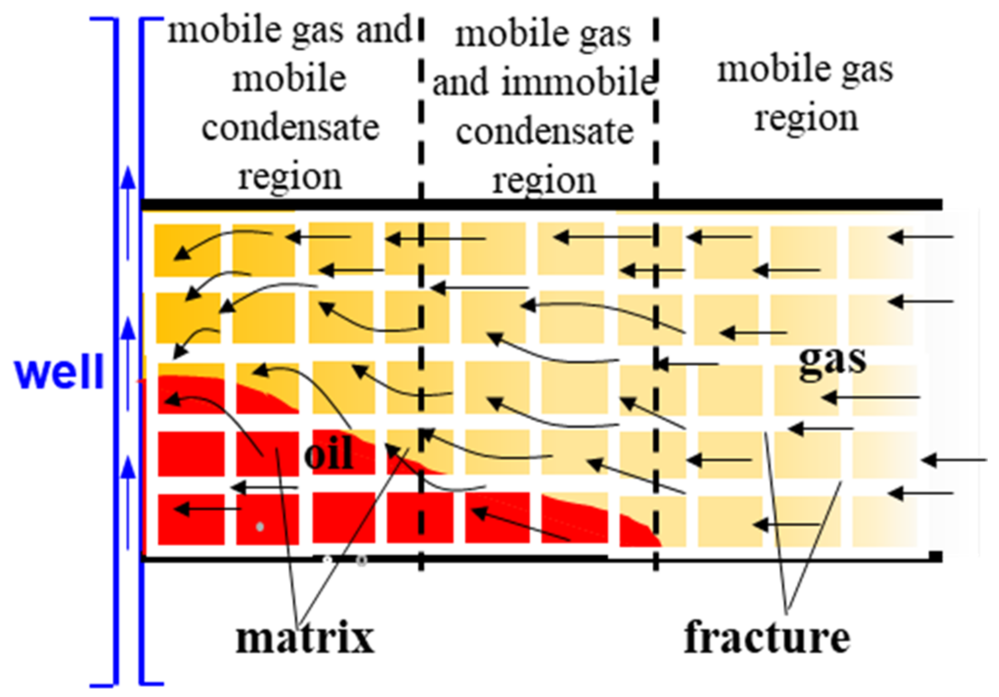
In this paper, a new well test model of a phase change vertical well with fractures was studied. In the process of a condensate gas multi-phase flow in formation, there were three different flow zones in the reservoir (as shown in Figure 1):
Zone I: oil and gas two-phase flow near the wellbore;
Zone II: the zone between zone I and zone III, which was a single-phase flow zone where condensate oil was precipitated, but did not flow;
Zone III: the zone away from the well where the formation pressure was above the dew point, which was a single-phase flow zone without condensate release.
Based on Darcy’s Law and the mass conservation method, the governing equation for the flow of the gas component in the gas condensate reservoir was yielded, which was derived on the basis of following assumptions:
- (a)
- The reservoir thickness was constant.
- (b)
- The flow of reservoir fluids was isothermal and obeyed Darcy’s law.
- (c)
- The initial pressure of the reservoir was Pi, which was higher than the dew point pressure.
- (d)
- The influences of the wellbore storage effect and skin effect were considered.
- (e)
- The Warren–Root model was used to describe the double-porosity reservoir.
- (f)
- Gravity and the capillary pressure were ignored.
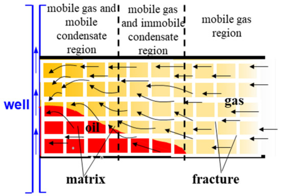
Figure 1.
The flow region of the condensate gas reservoir.
Figure 1.
The flow region of the condensate gas reservoir.
2.2. Analytical Model
We began with the well-known Warren–Root model in a dual-porosity reservoir [23]. According to the principle of the material balance, the continuity equation in the fracture could be expressed as:
The continuity equation in the matrix could be expressed as:
The interporosity flow was as shown in Equation (3):
According to Darcy’s law, the equation of motion could then be expressed as:
The flow from the matrix to the fracture was assumed to be in a pseudo-steady state, as shown in Equation (5):
The pressure-transient equations were based on the diffusivity equation (Equation (6)). Based on the basic theory of a multi-phase flow, the diffusivity equation was obtained by combining the mass conservation with the dual-porosity model.
In this equation, i = 1 and M = 1; when i = 2, M = M2 and when i = 3, M = M3.
In Equation (7), regions I, II, and III describe the behavior of pseudo-pressure (m(p)) at the near-wellbore region (the mobile gas and mobile condensate region in Figure 1), the middle region (the mobile gas and immobile condensate region in Figure 1), and the single-phase gas region (mobile gas region 3 in Figure 1), respectively [24].
where t = m,f.
The initial condition was:
The inner boundary conditions were:
The interface condition between region 1 and region 2 was:
The interface condition between region 2 and region 3 was:
The outer boundary condition (infinite reservoir) was:
We could then define the dimensionless variables (Table 1).

Table 1.
Dimensionless variables and definitions.
We could then express Equation (6) in the Laplace transformation as follows:
The initial conditions were:
The inner boundary conditions were:
The connection conditions of each region were:
The outer boundary condition was:
where:
The general solution to Equation (15) in the Laplace domain was:
Submitting Equation (27) into Equation (23), we obtained:
Submitting Equations (26) and (27) into Equation (22), we obtained:
Submitting Equations (25) and (26) into Equation (21), we obtained:
Submitting Equations (26) and (27) into Equation (20), we obtained:
Submitting Equations (25) and (26) into Equation (19), we obtained:
By submitting Equation (25) into Equations (17) and (18), the expression of the bottom-hole pressure was obtained:
Applying Equations (29)–(33) helped to generate the coefficients Ai and Bi. By combining all sub-segments, we generated a matrix system.
We solved the matrix to obtain the coefficients A1, B1, A2, B2, and A3.
The solution could be found by converting the Laplace domain result in Equation (33) to a time domain by using the Stehfest algorithm [25].
3. Results and Discussion
3.1. Type Curves
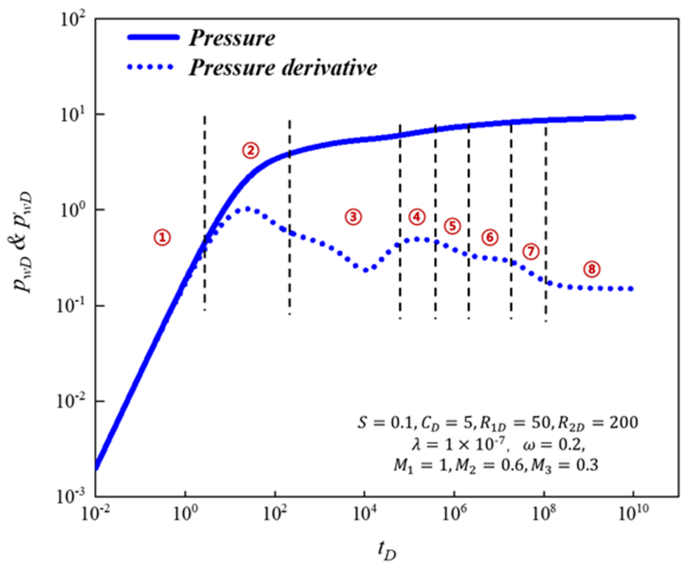
We present our type curve results for a two-phase flow, considering retrograde condensation. As shown in Figure 2, the typical signature of a well is the appearance of a “multi-step” pressure derivative curve. We identified eight flow regimes from the pressure and derivative curves.
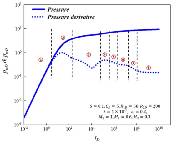
Figure 2.
Type curves of two-phase flow considering in a fractured gas condensate reservoir.
- Regime 1: The first flow regime was the wellbore storage regime. The pseudo-pressure curve and derivative curve were straight lines with a slope equal to 1, reflecting the effect of wellbore storage.
- Regime 2: The second regime was the transitional flow regime. The shape of the curve changed with the change in the value of the skin and wellbore storage coefficient.
- Regime 3: The third flow regime was the interporosity regime, which was characterized by a V-shape. It was mainly affected by a cross-flow from the fracture to the matrix.
- Regime 4: The forth flow regime was the first radial flow regime. The pseudo-pressure derivative curve transitioned to a horizontal straight line with a value of 0.5, reflecting the radial flow characteristics of the gas and condensate in the inner zone system in the formation.
- Regime 5: The fifth regime was called the second transitional flow regime between the first radial flow and the second radial flow.
- Regime 6: The forth flow regime was the second radial flow regime. The horizontal line of the pressure derivative reflected the radial flow characteristics of the gas system in the second zone of the formation.
- Regime 7: The seventh regime was called the third transitional flow regime between the second radial flow and the third radial flow.
- Regime 8: The forth flow regime was the third radial flow regime. The pseudo-pressure derivative was a horizontal line that reflected the radial flow characteristics of the gas in the third zone system in the formation.
3.2. Sensitivity Analysis
3.2.1. Different λ and w
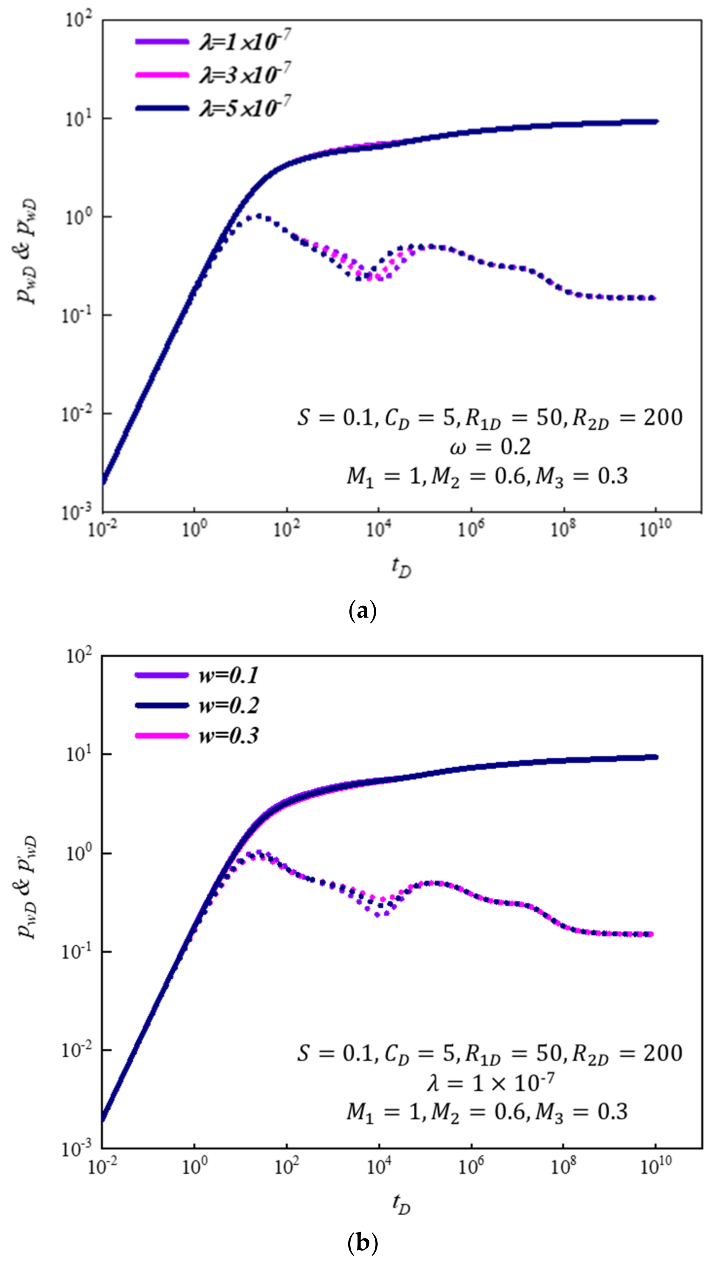
In the well test model of a vertical well in a gas condensate reservoir, it was assumed that other parameters were unchanged and λ took a set of parameters. The changes in the pressure and the pressure derivative curve are given in Figure 3a. It can be seen from the figure that with an increase in λ, the pressure derivative curve moved slightly to the left. Moreover, the cross-flow coefficient also played a partial shielding role on the derivative curve of pressure. As the value of λ increased, the characteristics of the first radial flow were obscured. This meant that the feature of the first radial flow overlapped with the feature of the interporosity regime. At this time, the characteristics of the radial flow could not be observed on the derivative curve and only the characteristics of the interporosity regime could be seen. The larger the λ value, the easier the fluid exchange between the matrix and fracture, the earlier the interpore state occurred, and the pressure derivative curve shifted slightly to the left.
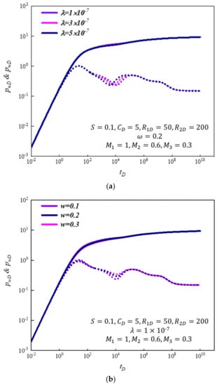
Figure 3.
(a) The comparison of type curves under different λ; (b) the comparison of type curves under different ω.
In the same way, assuming that other parameters were unchanged and the ω parameter was given a set of values, the changes in the pressure and the pressure derivative curve effect from the storage capacity ratio could be seen (Figure 3b). As the value of ω increased, the fracture storage ability decreased. With an increase in ω, the concave amplitude of the pressure derivative curve became larger and moved slightly to the left.
3.2.2. Different Mobility Ratio (Mi)
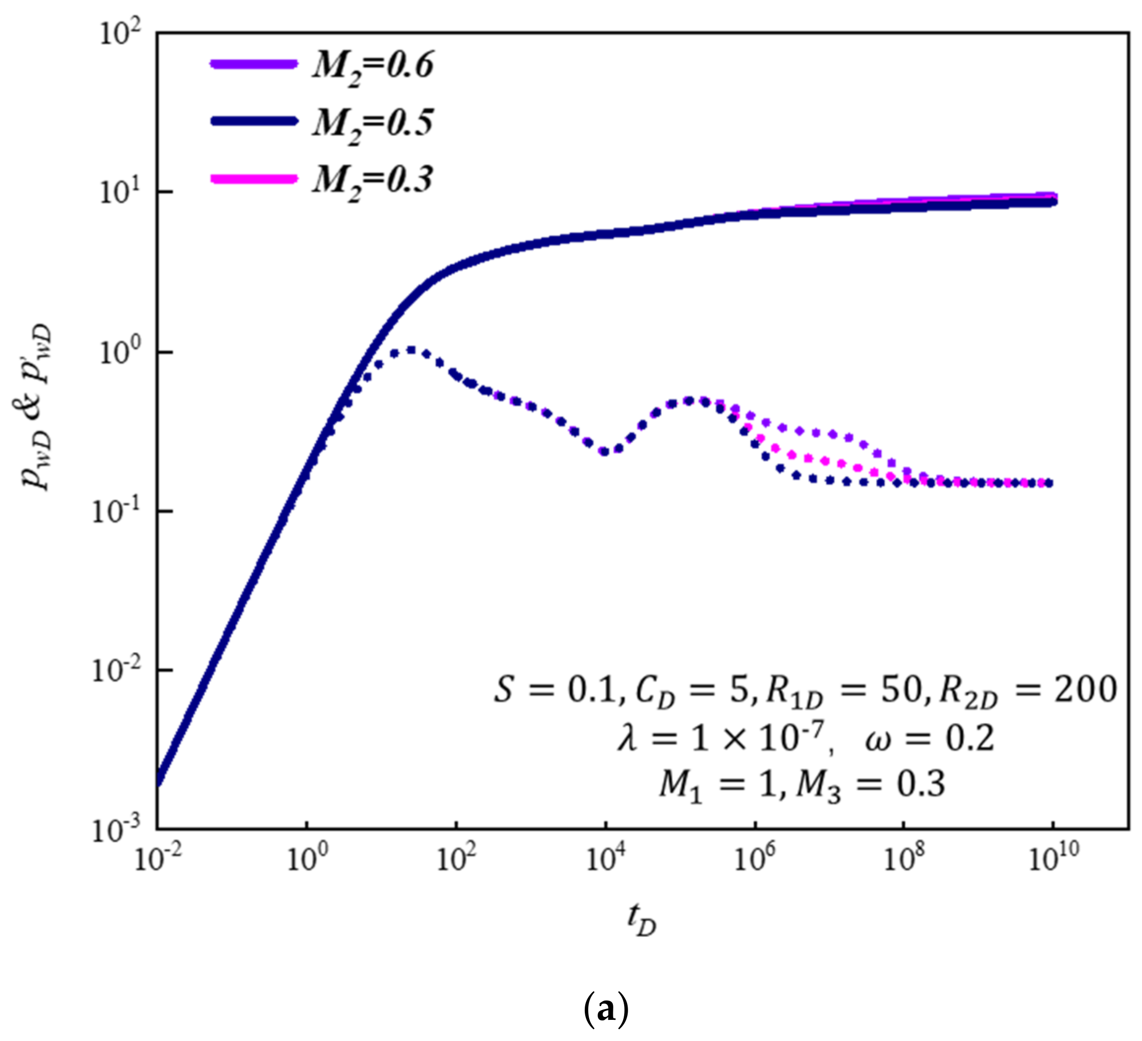
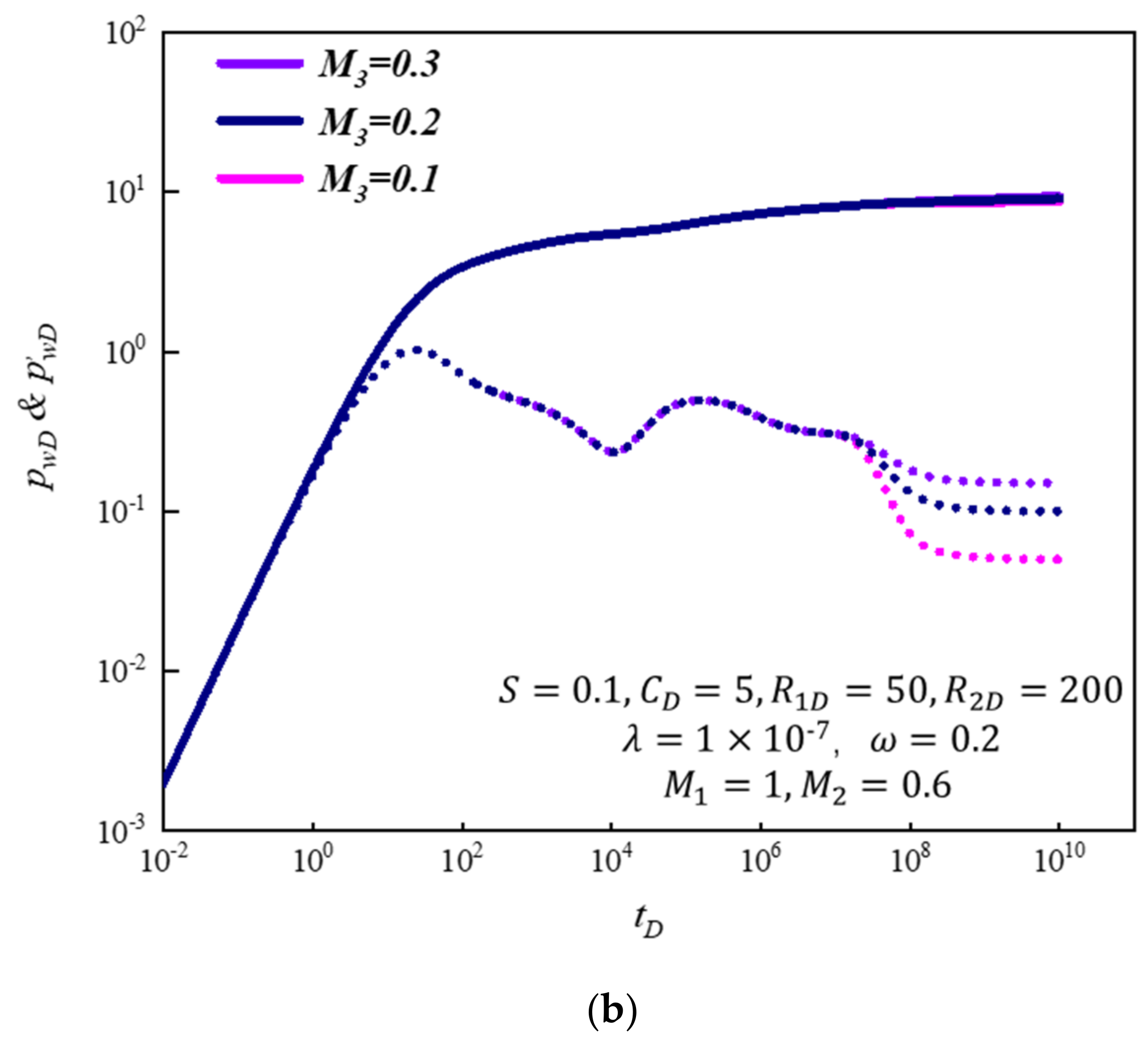
During the production process, mobility is a key factor influencing the fluid flow and pressure wave propagation. As shown in Figure 4, we assumed that the other parameters were constant and Mi was given a set of values. The results showed that mobility ratio on the pressure curve was not obvious, but the effect on the pressure derivative curve was more noticeable.
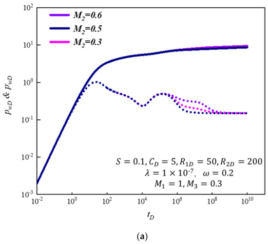
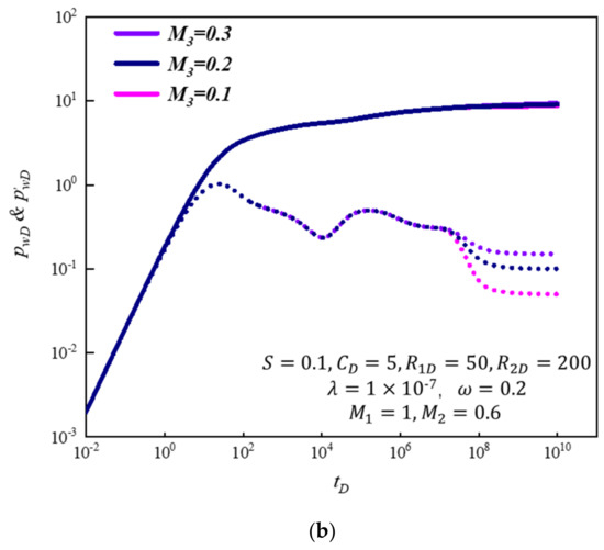
Figure 4.
The comparison of type curves under a different mobility ratio Mi: (a) zone I and zone II; (b) zone II and zone III.
As shown in Figure 4a, the influence of the fluidity ratio M12 on the pressure derivative curve mainly occurred in zone II and the fluidity ratio partially shielded the pressure derivative curve. When the fluidity ratio M2 = 0.3, the characteristics of the third region could not be accurately identified on the pressure derivative curve. When the mobility ratio M2 changed from 0.3 to 0.6, we noted that the pressure derivative rose after the first transition regime and reached a higher value during the radial flow in zone II.
The effect of the mobility ratio between zone II and zone III M3 was also analyzed. As shown in Figure 4b, this parameter mainly controlled the flow behavior of the third transition flow and radial flow in zone III. When M3 increased, the pressure derivative gradually increased and finally remained at a higher value, and the characteristics of the second transition flow became fuzzier.
3.2.3. Different Mobility Ratio (RDi)
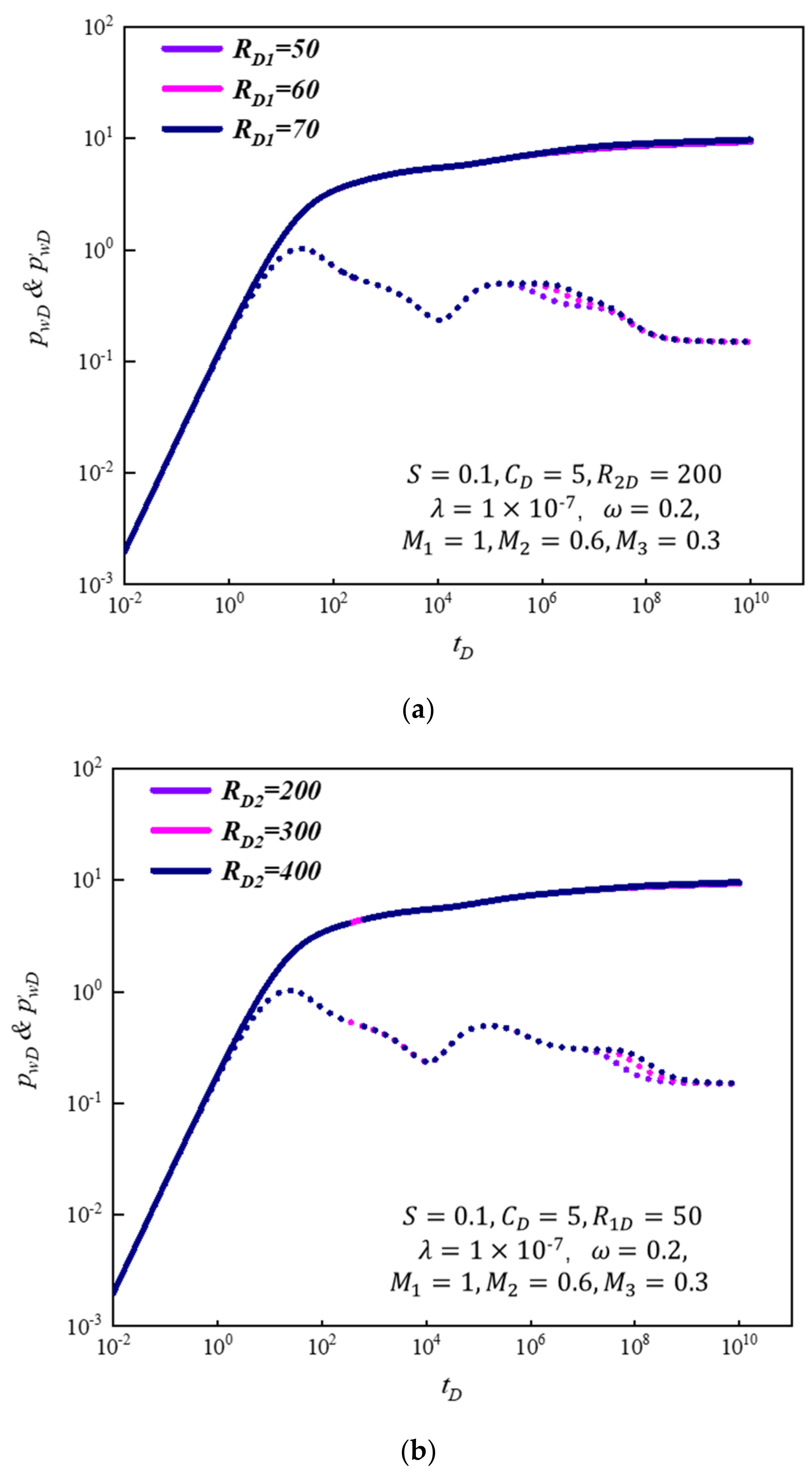
As described in the previous section, retrograde condensation occurs near the wellbore during production. Within a certain perimeter, oil and gas are mobile and the liquid saturation is higher than the critical saturation. As shown in Figure 5a, the radius of the inner region had a partial shielding effect on the derivative curve of pressure and the shielding effect increased with a decrease in RD1. When the radius of zone I increased, the radial flow in zone I lasted a long time; the value of the pressure derivative became larger during this period whereas the characteristics of the first transition zone and radial flow zone of zone II were not obvious.
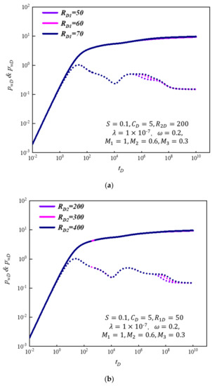
Figure 5.
The comparison of type curves under a different composite radius RDi: (a) zone I; (b) zone II.
Figure 5b shows the influence of the zone II radius on the double logarithm curve. RD2 mainly affected the radial flow and secondary transition flow in zone II. When RD2 increased from 200 to 400, the radial flow duration in zone II was prolonged and the occurrence time of zone III was delayed. Furthermore, by summarizing the research results, it could be concluded that when RD1 and RD2 were close, the double logarithm curve was more likely to show the characteristics of the two regions. In other words, if the radius difference between the two regions was not large enough, it was difficult to identify the features of the three regions.
3.3. Innovations and Limitations
The innovations of this paper are mainly reflected in the following aspects:
(1) We proposed an innovative approach to model a fractured gas condensate reservoir, considering retrograde condensation and natural fractures.
(2) The new model could interpret both the condensate plugging radius and the fracture parameters.
(3) The model was solved by the interpretation method, which is simple and can be conveniently applied to the engineering field.
There were a few limitations to our model. Our model used the double-porosity medium to characterize the natural fractures. That meant that there were natural fractures throughout the reservoir. Thus, reservoirs with locally developed fractures are not suitable for this model.
4. Case Study
When the pressure data of the field cases were obtained from the test, the pressure and its derivative curves could be preliminarily generated. According to the geological characteristics and the typical flow characteristics of the pressure and the pressure derivative curve, the appropriate well test model was selected for historical matching. However, the existing commercial software models have no suitable model matching the phenomenon that fracture features and composite features exist simultaneously. This session tried to illustrate that an analytical model of the fractured gas condensate reservoir proposed in this paper was necessary and accurate.
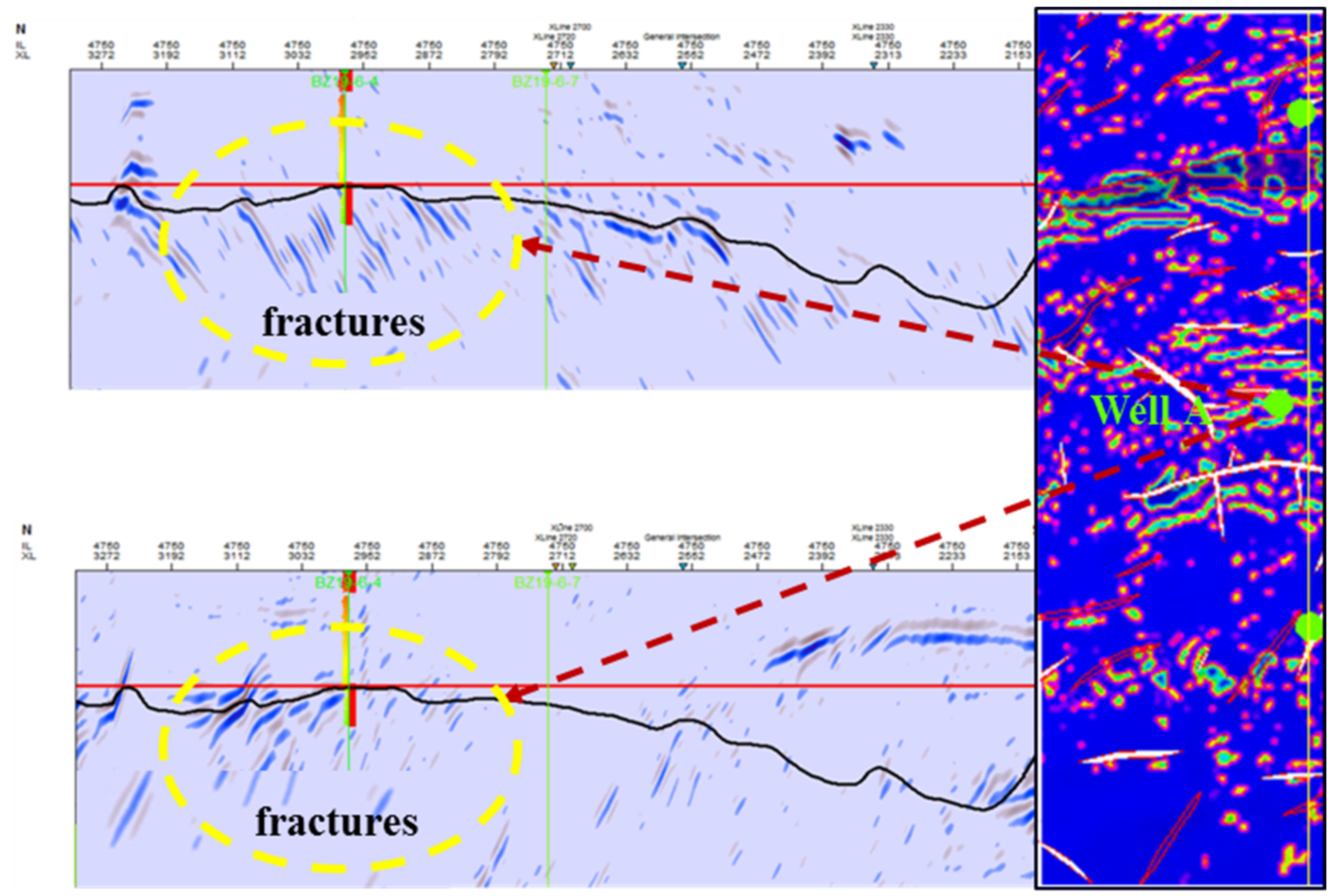
Well A was a condensate gas well put into the development of the BoHai oilfield in China. After a period of production, oil and gas began to be produced together. The condensate content reached 714 g/m3, which indicated a high oil-content condensate gas well. Figure 6 shows fractured condensate gas Well A. Therefore, we applied the proposed analytical solution to interpret the recorded pressure accumulation data.
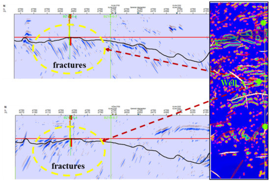
Figure 6.
The tests show fractures in the formation.
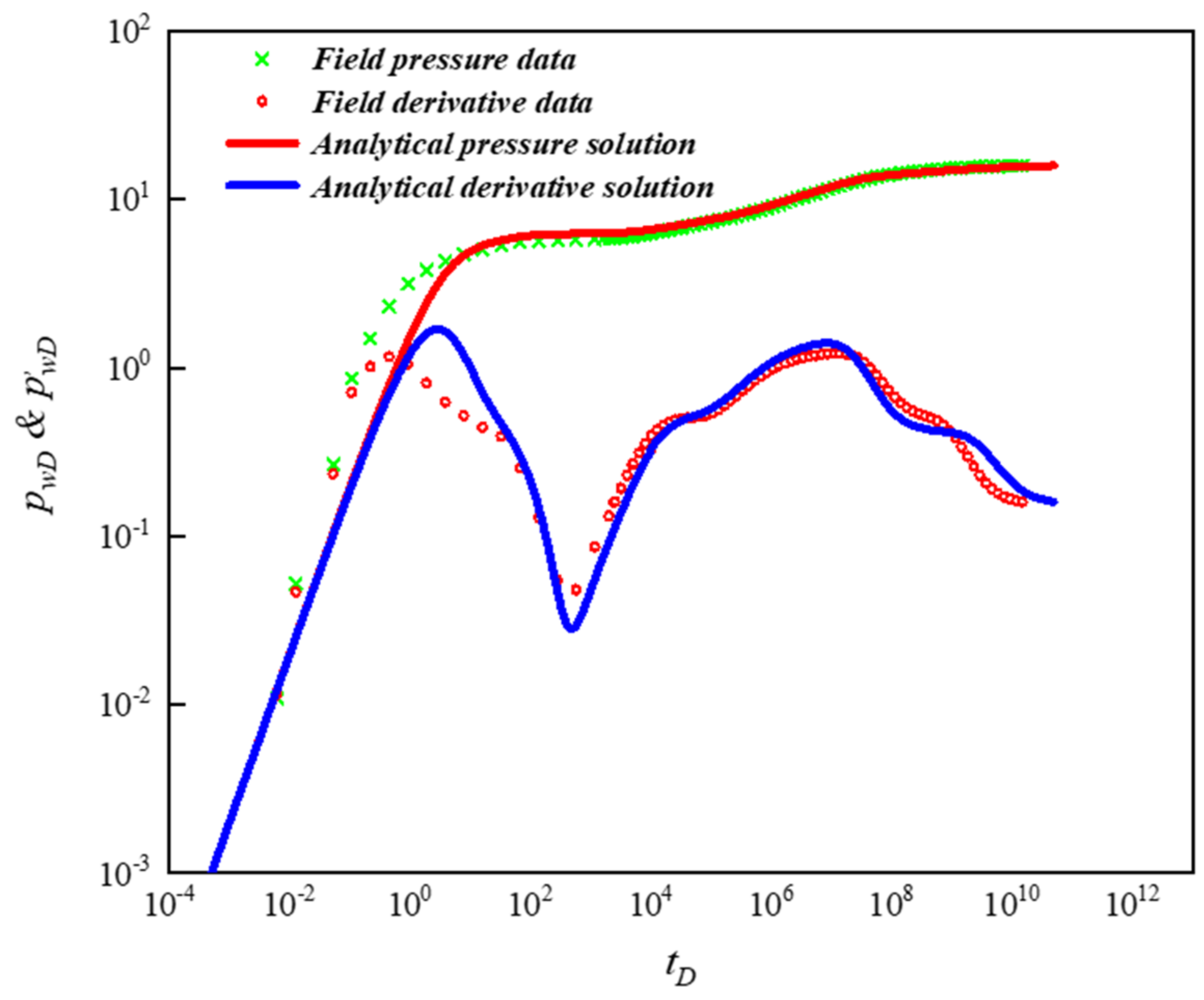
The basic parameters of the gas reservoir and gas well are shown in Table 2. It is clear from Figure 7 that the theoretical curve matched the recorded transient pressure. The recorded transient pressure curves not only had the characteristics of flow between the fracture and matrix pores, but also had the characteristics of a multi-region recombination. The interpretation results are shown in Table 3. It was observed that the interpretation results from our model matched well with the input data, which verified the reasonability of our model.

Table 2.
The reservoir of this field.
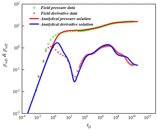
Figure 7.
The application of the proposed analytical solution.

Table 3.
The interpretations of the results of Well A.
5. Conclusions
As there is no existing analytical model for the pressure-transient analysis of a fractured gas condensation reservoir, this paper proposed a novel coupling model of a three-region model and a dual-porosity model to better analyze the pressure-transient behaviors. The following contributions and conclusions were inferred from this study:
- There were eight flow regimes for the model in the gas condensate reservoir, including the wellbore storage regime, transitional flow regime, interporosity regime, first radial flow regime, second transitional flow regime, second radial flow regime, third transitional flow regime, and third radial flow regime. The area composite radius had little influence on the pressure curve and was mainly on the pressure derivative, which was manifested in the appearance of the transitional flow regime between two adjacent areas. The fluidity ratio was similar to the area composite radius and the main influence was also on the pressure derivative curve, which was manifested in the upscaling or downscaling of the curve.
- The wellbore storage coefficient and skin factor mainly influenced the early production performance. The pressure derivative curve was mainly affected by the cross-flow coefficient and storage capacity ratio, which showed the amplitude of the V-shape and the time of its appearance.
- The derivative curve was sensitive to the composite radius. When the radius of zone I was small, the derivative curve did not appear in the radial flow horizontal line characteristic of zone I. When the difference between the zone I radius and zone II radius was small, only the horizontal line of the zone I radius appeared and the characteristics of the zone II radius were obscured.
- An increase in RD1 prolonged the radial flow time in zone I and also increased the value of the pressure derivative. Similarly, when the RD2 value increased, the duration of the radial flow in zone II extended. In addition, if RD2 was not large enough compared with RD1, it was difficult to observe the three-zone behavior.
The application of the model to explain the pressure-transient analysis of a condensate gas reservoir proved its superiority. The model proposed in this paper has a certain significance to guide the efficient development of condensate gas reservoirs.
Author Contributions
Methodology, F.Y.; Software, B.L.; Formal analysis, S.C.; Data curation, L.Z. and Y.W. All authors have read and agreed to the published version of the manuscript.
Funding
This research received no external funding.
Conflicts of Interest
The authors declare no conflict of interest.
Nomenclature
| So | oil saturation, % |
| Sg | gas saturation, % |
| φf | fracture porosity, % |
| φm | matrix porosity, % |
| q* | mass flow rate, kg/s |
| pm | matrix pressure, MPa |
| pf | fracture pressure, MPa |
| vo | oil flow rate, cm3/s |
| vg | gas flow rate, cm3/s |
| Kro | relative permeability of oil, 10−3μm2 |
| Krg | relative permeability of gas, 10−3μm2 |
| Ctf | fracture coefficient of compression, 1/MPa |
| Ctm | matrix coefficient of compression, 1/MPa |
| mm | pseudo fracture pressure, MPa |
| mf | pseudo matrx pressure, MPa |
| rD | dimensionless radial distance |
| t | time, h |
| tD | dimensionless time |
| pm | pressure in the matrix |
| mmD | dimensionless matrix pressure |
| pf | pressure in the fracture |
| mfD | dimensionless fracture pressure |
| pw | bottom hole pressure |
| mwD | dimensionless bottom hole pressure |
| p* | Reference pressure, MPa |
| pdew | Dew point pressure, MPa |
| pi | initial reservoir pressure, MPa |
| kmrg | relative permeability of gas in matrix, 10−3μm2 |
| kfro | relative permeability of oil in fracture, 10−3μm2 |
| μg | gas viscosity, mPa·s |
| μo | oil viscosity, mPa·s |
| ρg | oil density, kg/m3 |
| ρo | gas density, kg/m3 |
| C | wellbore storage coefficient, m3/MPa |
| CD | dimensionless wellbore storage coefficient |
| rw | wellbore radius |
| r | radial distance |
| M | Mobility ratio |
| u | Laplace variable |
| S | skin factor |
| λ | interporosity flow coefficient |
| ω | storativity |
| i | Zone i |
| 1,2,3 | Zone 1, Zone 2 and Zone 3 |
| a | matrix coefficient |
| Special Functions: | |
| I0(x) | Bessel function of the first kind |
| K0(x) | Bessel function of the second kind |
References
- Gholampour, F.; Mahdiyar, H. A new correlation for relative permeability in gas condensate reservoirs. J. Pet. Sci. Eng. 2019, 172, 831–838. [Google Scholar] [CrossRef]
- Behmanesh, H.; Hamdi, H.; Clarkson, C.R. Production data analysis of tight gas condensate reservoirs. J. Nat. Gas Sci. Eng. 2015, 22, 22–34. [Google Scholar] [CrossRef]
- Alireza, R.; Mohammad, B.; Rouhollah, D.; Mohammadi, A.H. Condensate blockage study in gas condensate reservoir. J. Nat. Gas Sci. Eng. 2016, 33, 634–643. [Google Scholar]
- Luis, F.A.; Turgay, E.; Michael, A. Numerical analysis of multi-mechanistic flow effects in naturally fractured gas-condensate systems. J. Pet. Sci. Eng. 2007, 58, 13–29. [Google Scholar]
- O’Dell, H.G.; Miller, R.N. Successfully cycling a low-permeability high yield gas condensate reservoir. J. Pet. Technol. 1967, 19, 41–47. [Google Scholar]
- Lal, R.R. Well Testing in Gas-Condensate Reservoirs; Stanford University: Stanford, CA, USA, 2003. [Google Scholar]
- Al Abdulwahab, I.; Jamiolahmady, M.; Whittle, T. Calculation of relative permeability using well test data in gas-condensate reservoirs. In Proceedings of the SPE Europec Featured at 80th EAGE Conference and Exhibition, Copenhagen, Denmark, 11–14 June 2018; Society of Petroleum Engineers: Dallas, TX, USA, 2018. [Google Scholar]
- Gringarten, A.C.; Al-Lamki, A.; Daungkaew, S. Well test analysis in gas-condensate reservoirs. In Proceedings of the SPE Annual Technical Conference and Exhibition, Dallas, TX, USA, 1–4 October 2000; Society of Petroleum Engineers: Dallas, TX, USA, 2000. [Google Scholar]
- Martin, J.C. Simplified equations of flow in gas drive reservoirs and the theoretical foundation of multiphase pressure buildup analysis. Trans. AIME 1959, 216, 309–311. [Google Scholar] [CrossRef]
- Fussell, D. Single-well performance predictions for gas condensate reservoirs. J. Petrol. Technol. 1973, 25, 860–870. [Google Scholar] [CrossRef]
- Sognesand, S. Long-term testing of vertically fractured gas condensate wells. In Proceedings of the SPE Production Operations Symposium, Oklahoma City, OK, USA, 7–9 April 1991. Paper 21704. [Google Scholar]
- Yu, X.; Lei, S.; Tian, S.L.; Shilun, L. A New Method for Predicting the Law of Unsteady Flow Through Porous Medium on Gas Condensate Well. Soc. Pet. Eng. 1996, SPE-35649-MS. [Google Scholar] [CrossRef]
- Li, X.; Cheng, S.; Qin, B.; Tong, M.; Guan, W. Some problems in development and production of gas condensate reservoirs. Oil Drill. Prod. Technol. 2003, 5, 47–50+95. [Google Scholar]
- Kool, H.; Azari, M.; Soliman, M.Y.; Proett, M.A.; Irani, C.A.; Dybdahl, B. Testing of gas condensate reservoirs e sampling, test design and analysis. In Proceedings of the SPE the Asia Pacific Oil and Gas Conference and Exhibition, Jakarta, Indonesia, 17–19 April 2001. Paper 68668. [Google Scholar]
- Clarkson, C.R.; Williams-Kovacs, J.D.; Qanbari, F.; Behmanesh, H.; Heidari Sureshjani, M. History-matching and forecasting tight/shale gas condensate wells using combined analytical, semi-analytical, and empirical methods. J. Nat. Gas Sci. Eng. 2015, 26, 1620–1647. [Google Scholar] [CrossRef]
- Zeng, F.; Zhao, G. Semi-analytical model for reservoirs with Forchheimer’s non-darcy flow. SPE Res. Eval. Eng. 2008, 11, 280–291. [Google Scholar] [CrossRef]
- Sureshjani, M.H.; Behmanesh, H.; Clarkson, C.R. A new semi-analytical method for analyzing production data from constant flowing pressure wells in gas condensate reservoirs during boundary-dominated flow. In Proceedings of the SPE Western North American and Rocky Mountain Joint Meeting, Denver, CO, USA, 17–18 April 2014; Society of Petroleum Engineers: Dallas, TX, USA, 2014. [Google Scholar]
- Behmanesh, H.; Hamdi, H.; Clarkson, C.R. Production data analysis of gas condensate reservoirs using two-phase viscosity and two-phase compressibility. J. Nat. Gas Sci. Eng. 2017, 47, 47–58. [Google Scholar] [CrossRef]
- Wang, Y.; Cheng, S.; Zhang, K.; Ayala, L.F. Investigation on the Transient Pressure Response of Water Injector Coupling the Dynamic Flow Behaviors in the Wellbore, Waterflood-Induced Fracture and Reservoir: Semi-Analytical Modeling and A Field Case. Int. J. Heat Mass Transf. 2019, 130, 668–679. [Google Scholar] [CrossRef]
- Wang, Y.; Ayala, L. Explicit Determination of Reserves for Variable Bottom-hole Pressure Conditions in Gas Well Decline Analysis. SPE J. 2020, 25, 369–390. [Google Scholar] [CrossRef]
- Wei, C.; Liu, Y.; Deng, Y.; Cheng, S. Analytical well-test model for hydraulicly fractured wells with multiwell interference in double porosity gas reservoirs. J. Nat. Gas Sci. Eng. 2022, 103, 104624. [Google Scholar] [CrossRef]
- Wei, C.; Liu, Y.; Deng, Y.; Hassanzadeh, H. Temperature Transient Analysis of Naturally Fractured Geothermal Reservoirs. SPE J. 2022, 27, 2723–2745. [Google Scholar] [CrossRef]
- Warren, J.E.; Root, P.J. The behaviorofnaturally fracturedreservoirs. Soc. Pet. Eng. J. 1963, 3, 245–255. [Google Scholar] [CrossRef]
- Fevang, Ø.; Whitson, C. Modeling gas-condensate well deliverability. SPE Reserv. Eng. 1996, 11, 221–230. [Google Scholar] [CrossRef]
- Stehfest, H. Algorithm 368: Numerical inversion of Laplace transforms [D5]. Commun. ACM 1970, 13, 47–49. [Google Scholar] [CrossRef]
Publisher’s Note: MDPI stays neutral with regard to jurisdictional claims in published maps and institutional affiliations. |
© 2022 by the authors. Licensee MDPI, Basel, Switzerland. This article is an open access article distributed under the terms and conditions of the Creative Commons Attribution (CC BY) license (https://creativecommons.org/licenses/by/4.0/).

