Review

Integration of Renewable Energy Sources into Low-Temperature District Heating Systems: A Review

Department of Civil and Building Services Engineering, Polytechnic University Timisoara, Piata Victoriei, no 2A, 300006 Timisoara, Romania
*
Author to whom correspondence should be addressed.
Energies 2022, 15(18), 6523; https://doi.org/10.3390/en15186523
Submission received: 1 August 2022 / Revised: 27 August 2022 / Accepted: 3 September 2022 / Published: 7 September 2022
(This article belongs to the Section G: Energy and Buildings)

Abstract

:
This article presents a complex and exhaustive review of the integration of renewable energy sources (RES) (specifically solar, geothermal, and hydraulic energies and heat pumps (HPs)) and the improvement of water pumping in district heating systems (DHSs) focused on low-temperature systems, to increase energy efficiency and environmental protection. For this aim, the main components of a DHS and the primary RES with applications in DHSs were described briefly. Finally, several case studies regarding the DHS in Timisoara, Romania, were analysed. Thus, by integrating water source HP (WSHP) systems in cooperation with solar thermal and photovoltaic (PV) collectors and reducing the supply temperature from 110 °C to 30 °C in DHS, which supplies the water radiators to consumers in a district of this city in a 58/40 °C regime of temperatures and produces domestic hot water (DHW) required by consumers at 52 °C, a thermal energy saving of 75%, a reduction in heat losses on the transmission network of 90% and a diminution of CO2 emissions of 77% were obtained. Installed PV panels generate 1160 MWh/year of electricity that is utilised to balance the electricity consumption of HP systems. Additionally, mounting pumps as turbines (PATs) for the recovery of excess hydraulic energy in the entire heating network resulted in electricity production of 378 MW, and the variable frequency drive’s (VFD) method for speed control for a heating station pump resulted in roughly 38% more energy savings than the throttle control valve technique.

1. Introduction

Regardless of its form, energy is an indispensable resource that ensures a good quality of life in contemporary civilisation. Europe’s culture and traditions are inextricably linked to its buildings, which also play a crucial part in the continent’s energy strategy. Around 40% of the energy demand in the European Union (EU) is used by buildings, followed by industry and transportation, which take about 30% of the total energy demand each [1]. Presently, thermal building needs (space and water heating) account for over 80% of the energy requirement in the residential domain, although the energy demand for cooling is increasing annually. Greenhouse gas (GHG) emissions, increasing energy consumption, and a growing reliance on imports are significant energy issues that every nation must address. Carbon dioxide (CO2) is one of the most significant GHGs, and the burning of fossil fuels is the dominant source of CO2, contributing to the increase in atmospheric concentration.
The European building sector uses roughly 46% of energy for heating and cooling [2] and generates significant GHG emissions from the burning of fossil fuels to cover this energy demand. By 2030, the EU intends to reduce greenhouse gas emissions by 55% and boost its use of renewable energy sources (RES) to 40% [3]. Under Directive 2010/31/EU [4], all new buildings must be nearly zero-energy buildings (NZEB) by 2020. This directive defines NZEB as high-efficiency buildings with very low energy usage that RES primarily powers.
According to studies, saving energy is the most efficient way to minimise GHG emissions. This includes rehabilitation technologies, RES integration, and energy-efficient heating, ventilation, and air conditioning (HVAC) equipment. The primary objectives of district heating systems (DHSs) are to ensure appropriate interior comfort at a lower cost and to minimise GHG emissions, both of which can be attained with modern equipment and control methods. The primary benefit of DHSs is that they can be incorporated into existing heating installations at a reasonable cost, employing a combination of RES and traditional fuels.
Table 1 [5] presents the growth of DH infrastructures in several EU nations [6,7]. District heating (DH) helps to centralise heat production and perhaps electricity and the distribution of this energy to a network of users [8]. A DHS distributes heat from a central heating station to consumers for space and/or process heating and domestic hot water (DHW) preparation. The heat is transmitted using hot water or steam pipes. Thus, heat is derived from a hot fluid and not locally generated at each facility [9]. In view of the present challenges, it is vital to building DHSs to manage the energy transition period (e.g., integration of RES). In addition, safety and flexibility in choosing the heat source (solar and geothermal energy, or biomass instead of fossil fuels) are important characteristics of DHSs [10].
The EU has projected that DH networks will provide 50% of its heating needs in 2050 [11]. The DH network is a primary component of all DHSs, and its investment cost may equal or exceed 50% of a DHS’s total capital cost [12,13]. It is possible to reduce the cost and energy consumption of the DH network by optimising its design and operation [5].
Lund et al. [14] established four generations of DH, while Buffa et al. [15] expanded the concept by suggesting a fifth generation of DH and cooling (DHC). Traditional DHSs have heating stations (HSs) that inject hot water or steam through pipes to heat metropolitan areas. High-temperature DH systems continue to incur significant heat losses and expensive installation fees. Due to the high water retention period in the network, heat losses can reach approximately 30% of the supplied energy, particularly in the summer when the majority of DH systems are operating to fulfil DHW demand. Current research focuses on networks of the fourth generation DH (4GDH) and fifth generation DHC (5GDHC), which operate at low temperatures and achieve great efficiencies.
The trend is toward using 4GDH networks [14] to integrate a more significant proportion of RES and low-grade waste heat into the system. Other objectives include reducing heat losses in networks and increasing the efficiency of producing equipment (heat pumps (HPs), solar collectors, combined heat and power (CHP) plants, and condensing boilers). In 4GDH systems, however, the same pipes cannot simultaneously supply heating and cooling services to many buildings, unlike in 5GDHC systems.
Another advantage of the switch to lower temperatures in the DH network is the possibility to utilise polymer pipes instead of steel pipes, therefore simplifying and reducing the cost of installation. Typically, the design depicts two or three lines insulated with polyurethane foam and housed within the same casing. In order to improve the design of pipes for low-temperature district heating (LTDH), the heat losses of double (same and different diameters) and triple pipes were modelled [16].
This article offers an exhaustive review of the operational optimisation of DHSs to promote energy efficiency and environmental protection, focusing on integrating LTDH networks and RES. Therefore, the fundamental components of a DHS (heat sources, distribution network, and end-users) and the principal RES (such as solar, geothermal, hydraulic energies, and HP) with applications in DHSs are briefly described. In addition, a case study for Timisoara, Romania, is included regarding the integration of RES in the form of a solar-assisted HP system (HPs, solar thermal (ST), and photovoltaic (PV) panels) into a 3GDH system. This heating system was converted into a low-temperature 4GDH system with radiators serving as heating terminal units for consumers. Another case study investigates the installation of micro hydro-turbines in DHSs to recover excess hydraulic energy (pressure) into electricity. Finally, comparative energy analysis was performed on the hot water flow rate regulation utilising throttle valve control and variable-speed drive in a DH station built in Timisoara, and the performance of these control methods was evaluated. Engineers working on the implementation and theory of DHSs may benefit from this study’s extensive and up-to-date information.
This article’s primary purpose is the energy optimisation of DHSs, whose priority objectives are: (1) the enhancement of the system’s energy efficiency by integrating RES and introducing micro-hydropower technology to recover excess energy or by improving pumping; (2) the reduction in water and heat losses; (3) the diminution of CO2 emissions; and (4) the facilitation of access to a variety of sources for readers.

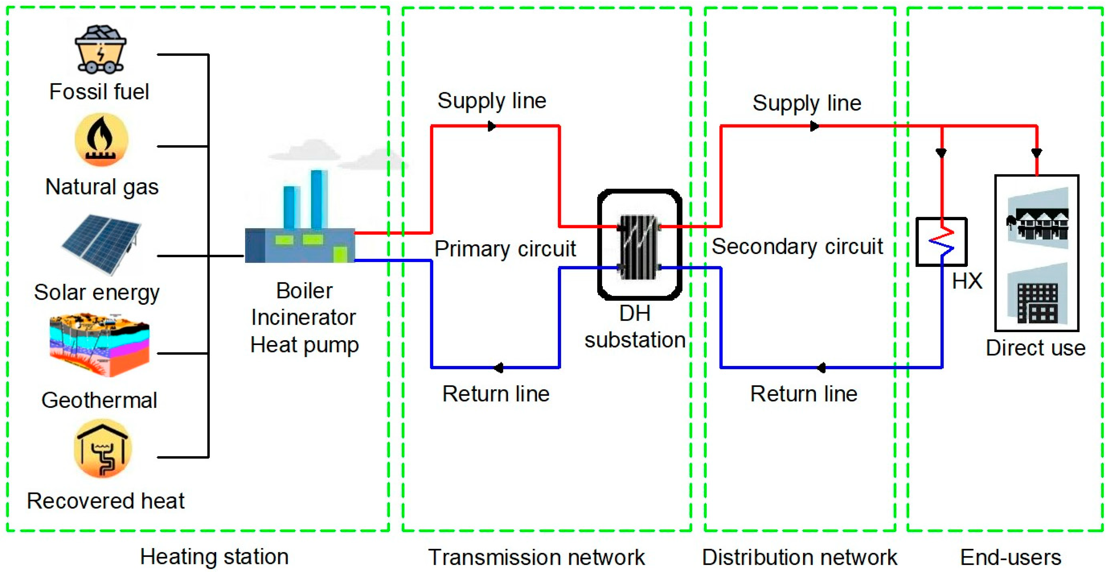
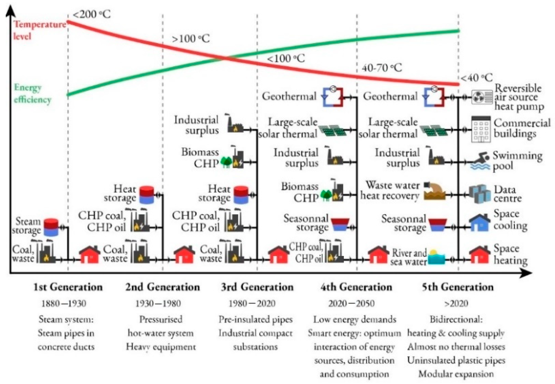
2. Configuration of a District Heating System

Traditional DHSs are comprised of central HSs that pump hot water or steam through pipes to provide heat to metropolitan areas. A DHS incorporates a heat generating unit (HS), transmission and distribution network, substations, and heat consumers (end-users) (Figure 1).

2.1. Heat Source

The heat providers in a DHS must consistently satisfy the requirements of the end-users. As the heat load of end-users fluctuates dramatically, manufacturers must adapt to meet the heat requirement. Permanent (heat production consistently exceeds network heat demand) and non-permanent (heat production varies relative to network heat demand) heat sources are often distinguished in an HS.
The majority of DHSs utilise diverse energy sources, including coal or natural gas [17] and industrial waste heat and waste incineration [18] or incorporate RES, such as geothermal and solar [19,20]. The HS relies on a traditional boiler or an incinerator, an HP, solar or geothermal energy, or the heat generated as a by-product of electricity production, often known as cogeneration. The principal cogeneration technologies consist of steam turbines, gas turbines, internal combustion engines, organic Rankine cycle technology, and Stirling engines.
It is general knowledge that biomass-type wastes are currently utilised for cogeneration as a renewable source of green energy. Through the combustion of fossil fuels or biomass, a cogeneration facility satisfies users’ power and heat demands.
The energy efficiency of a simple HS may range from 20 to 35%, but a cogeneration facility can have an energy efficiency of over 80%. In the situation where the two sources of energy are generated independently, the total energy efficiency does not exceed 57% [17]. A significant benefit to such heat generation is the substantially reducing carbon and waste heat emissions.
The surplus industrial heat is recoverable and utilised in a DHS [21]. The incorporation of RES into DHS results in output temperatures that are lower than those of a typical DH network supply. In this context, the geothermal DHS that utilise HPs has attracted growing interest in a number of nations over the last several years since it permits the sustainable replacement of fossil fuels and creates zero CO2 [20,22,23,24]. Additionally, nations such as Sweden, Denmark, Germany, and Austria have been increasing their usage of solar energy for DH [19,25].

2.2. District Heating Network

The DH network transfers heat from the HSs to the end-users using pipes, valves, pumps, fans, heat exchangers (HXs), and measurement and automation equipment [26,27].
The DH network comprises pre-insulated and field-insulated pipes that convey a hot fluid to end-users, where the fluid’s heat is transferred to an HX. The fluid cools and returns to the HS, which heats the cold water to restart the cycle.
The DH network scheme is seen in Figure 1. In the primary circuit, hot water travels through a transmission network to the DH substation and then returns to the heat source. In the secondary circuit (distribution network), water receives heat from the hot fluid in the primary circuit by HXs; this heat is then transferred to rooms via heating terminal units.
The first part (supply line) of a distribution network consists of a series of pipes that transport hot fluid from the DH substation to the end-users. The second side (return line) consists of the pipes that return cooled fluid from the end-users to the DH substation. Supply and return pipes are often coupled with identical physical and geometric characteristics. The heat loss Q ˙ h l , i j in a pipe ij, in W, is expressed as follows:
Q ˙ h l , i j = m ˙ i j c p ( t i t j )
where m ˙ i j is the mass flow rate through pipe ij, in kg/s; cp is the water-specific heat at constant pressure, in J/(kg·K); ti and tj are the inlet and outlet water temperatures in pipe ij, in K.
The addition of intermediary booster pumps to the network’s supply/return line overcome pressure drop in the HXs at the source and in the pipes, compared to the situation when just grid pumps are in service.
There are typically four distinct generations of heat distribution networks [28]. The 1GDH network transported steam at temperatures above 200 °C in concrete pipes. As a result, it was not particularly effective and was changed due to the risk of pipe explosions. The 2GDH network utilised concrete pipes to transport pressurised water at temperatures above 100 °C and is known as the high-temperature DH network. The 3GDH network employs pre-insulated pipes directly buried in the soil and operates with water at supply temperatures ranging between 65 and 95 °C. The modern 4GDH network is now being created and is frequently referred to as a low-temperature (50–60 °C) DH network [18]. When end-user temperatures for HPs are boosted, ultra-low supply temperatures (35–45 °C) are also used [29]. The 5GDHC networks are an extension of ground-source HP (GSHP) systems at the district scale. A 5GDHC network is a thermal energy supply system with reduced heat losses that employs water or brine as a heat carrier at a supply temperature of 0 °C to 30 °C, also known as ambient (free-floating) temperature and hybrid substations with water source HPs (WSHPs) [15]. The heat supplied by 5GDHC networks cannot be utilised directly to satisfy buildings’ space heating and DHW demand. Therefore, a WSHP is always required in “prosumer” substations to raise the supply temperature to an appropriate level for heat distribution and usage. The term “prosumer” was invented because, in principle, each end-user may operate as either a “consumer” or a “producer” of thermal energy to the network. By reversing the thermodynamic cycle of the WSHP, the 5GDHC substation can provide both the building’s heating and cooling demands. An attractive application of 5GDHC is its usage as an energy storage system.
Temperature reductions in DH networks are constrained by the heat demands and technical specifications of residential and commercial buildings (DHW demands or design of the space heating installations). Table 2 defines the different DH network types in line with the technical requirements of the buildings, appropriate heating terminal units, and the preceding definitions. Recent investigations suggested that low-temperature DH presents significant potential for space heating in existing buildings [30]. Figure 2 illustrates the needed supply temperatures for radiators in space heating systems for buildings with varying heat requirements [31].

2.3. End-Users

The end-users contain HVAC equipment in buildings. The heat produced at the HS is transported to the end-users through a network of insulated pipes. They provided hot water that may be used directly by the HVAC system of the building or indirectly via an HX [32], which transfers heat from one medium to another. A valve regulates the mass flow rate in the HX to manage the heat transfer percentage and maintain a constant temperature at the end-user.
Depending on the local climate, urban consumers of thermal energy needed for heating have a seasonal function with a longer or shorter length. Throughout the year, consumers should have access to DHW with the same DH network utilised for heating.
To assess user needs, diverse deterministic and stochastic techniques, such as the degree-day method [33], bin method [34], simulation-based models [35,36], regression models [37], and artificial neural network (ANN) algorithms [38], were published in the literature.
Typical consumer heat demand in a DHS is 20–22 °C for space heating and 50 °C for DHW. Existing DH networks have yearly average supply temperatures between 75 and 90 °C and annual average return temperatures between 40 and 50 °C [39]. According to research, radiators are often oversized and may operate effectively at low supply temperatures without compromising thermal comfort [40]. To reduce return temperatures is essential to modify the radiator discharge and supply temperature by utilising one of Johansson’s [41] suggested approaches.
As seen in Figure 3, DHSs have developed over time globally in terms of heat sources, equipment, and building heating systems [42]. The third generation restricts the incorporation of low-heat RES (solar and geothermal energy), which can minimise CO2 emissions.
New LTDH systems and prosumers’ integration require new network designs and configurations. Among these new designs and layouts are the cascade connexion of new low-temperature end-users to the return pipe [43], looped heating and cooling networks [44], ambient networks [45], multiple pipe networks of various temperatures [46], and appliances for hydraulic separation of the circuits [47].

3. Renewable Energy Sources

Renewable energy is derived from non-exhaustible and naturally renewable natural resources. Solar, geothermal, wind, biomass, and hydropower are examples of RES.
Romania offers an excellent mix of solar, geothermal, hydroelectric, and biomass energy potential [48]. Solar, geothermal, and biomass resources are the most appropriate renewable energies for heating/cooling. Table 3 summarises the energy potential of each resource type [49].
Various strategies might be investigated for reducing primary energy usage caused by fossil fuels and CO2 emissions from space heating and cooling [32]:
  • Integrating renewable energy based on ST collectors;
  • Solar PV panels interacting with an electric HP-based space heating and cooling system;
  • Solar thermal aided electric HP;
  • Use of energy conversion systems with high efficiency (condensing boiler, cogeneration system, GSHP).

3.1. Solar Energy

In recent years, scientists’ interest in solar energy has increased. For solar energy to be utilised, it must convert into other types of energy. Principal uses for solar technologies require low-temperature heat, such as space heating, domestic water heating, pool heating, and some industrial processes.

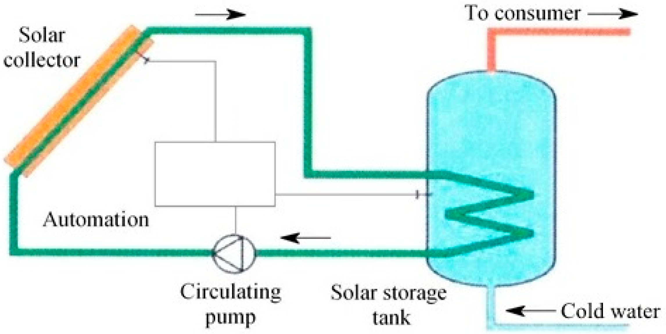
3.1.1. Solar Thermal Systems

The solar collector is the essential component of a solar system. ST collectors are a subset of HXs that use a heat transfer fluid (HTF) to convert solar light into thermal energy. There are several ST collectors available on the market [26].
Generally, a system for transforming solar energy to thermal energy consists of the following components (Figure 4): solar collectors (panels); heat storage schemes; circulating pumps; a heat transmission and distribution network; and automation, control, and safety equipment [50]. This system can provide heat for space heating and DHW production. If solar energy is insufficient, a secondary energy source is utilised.
The solar fraction (f) is the proportion of the total thermal load fulfilled by solar energy and is calculated as follows:
f = Q s o l Q s o l + Q a u x
where Qsol is the solar energy provided to the system, in kJ, and Qaux is the auxiliary energy, in kJ.
A solar combisystem (SCS) offers both solar space heating/cooling and hot water from a single array of ST collectors, often supplemented by a non-solar heat source [51]. Europe has the most developed solar thermal applications market [52]. The yearly space heating contribution in ultra-low energy buildings may range between 10 and 60%, depending on the size of the SCS used. Table 4 provides a summary of the primary SCS studies in the literature.
Solar DH is the supply of central heating and hot water utilising solar energy through a system in which water is heated by the ST collector field and distributed via DH pipe networks. DH is best appropriated to locations with a large population, construction density, and colder weather. Solar collectors can be put on the ground for DHSs.
Solar DHSs can provide heat to buildings supplied from the secondary circuit via DH substations or can be connected to the return pipe of the DH primary circuit in HS. DH has advanced substantially over the past few decades, considered the most effective technology for heating a building’s interior. Some studies concentrated on the coupling of DH and CHPs, renewable energy (solar and geothermal heat, or HPs), and industrial heat recovery [9,60,61,62].

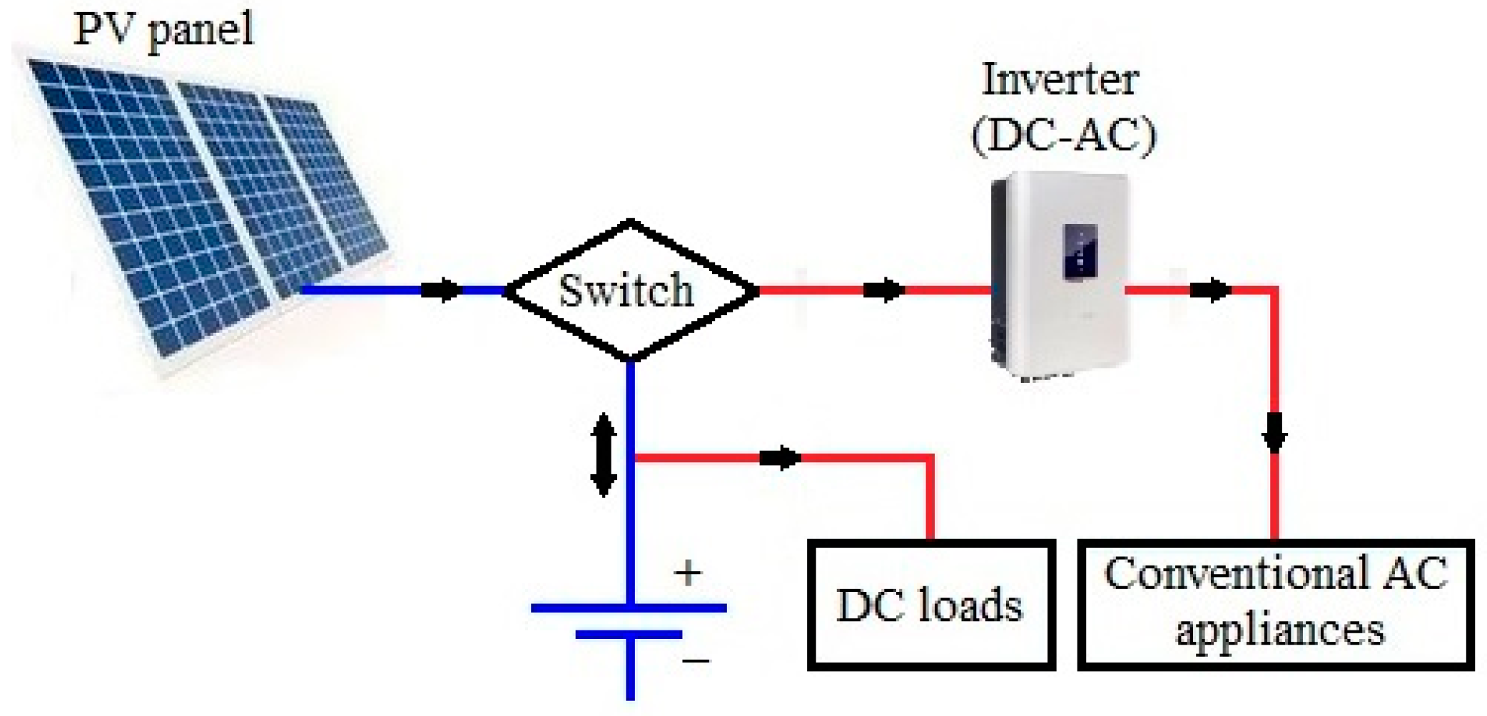
3.1.2. Solar Photovoltaic Systems

Solar PV systems provide a safe and ecologically sustainable energy source, among other advantages. In tandem with conventional power plants, PV-based electricity generation has increased fast worldwide during the past two decades [63] in response to the rising demand for electrical energy. Solar PV production in most nations is contingent on the kind of policies implemented by that country.
Solar PV systems absorb light radiation (in the ultraviolet and visible spectrum) using PV cells integrated into solar panels to generate energy. PV systems can be network-disconnected (stand-alone) or grid-connected (on-grid).
While the typical output of a PV panel is direct current (DC) electricity, the vast majority of household and commercial electrical equipment utilise alternating current (AC). Consequently, a typical solar PV system has four fundamental components (Figure 5): PV panels, a battery, an inverter, and a vapour-compression AC unit [64].
The PV panel is composed of cells that allow photons to “knock” electrons out of a molecular lattice, releasing an electron and “hole” pair that diffuses across an electric field to separate contacts, so producing DC energy.
The battery stores DC voltages in a charging mode when sunlight is present and provides DC electricity in a discharging mode when sunlight is absent. A battery charge regulator may prevent the battery from being overcharged. The inverter is an electrical circuit that transforms DC electricity to AC and subsequently supplies the AC consumers with electrical energy. In reality, the vapour-compression AC unit is a regular heating or cooling system powered by an inverter.
The PV system can function as an independent, hybrid system (operating with an oil/hydro/gas power facility), grid or utility intertie system.
A photovoltaic/thermal (PV/T) hybrid collector transforms solar energy into electricity and heat. The energy performance of commercially available PV/T systems for electricity and DHW generation was examined in three European nations [65].
Demand for solar PV is growing and has become the most competitive option for power generation in multiple markets (for residential and commercial applications) [66].

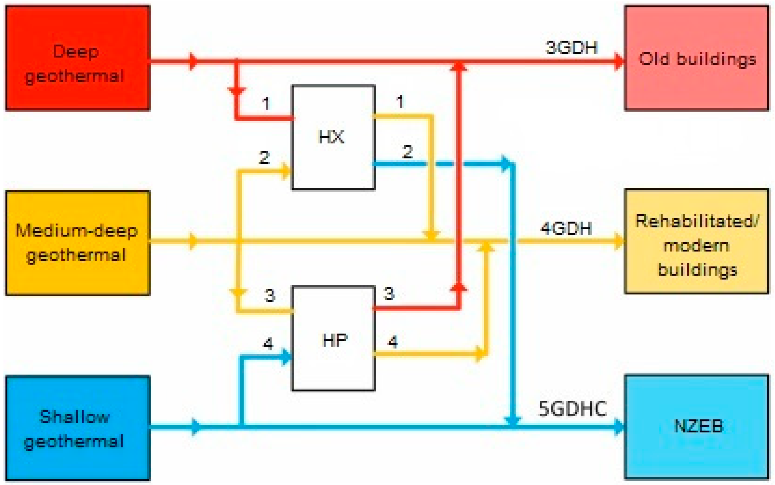
3.2. Geothermal Energy

Geothermal energy is stored in the Earth’s crust. With increasing depth within the Earth’s crust, temperature, and pressure rise, geothermal energy may be more effective. Low-enthalpy geothermal resources (temperatures below 200 °C) are primarily employed for direct heating applications, whereas high-enthalpy geothermal resources (temperatures over 200 °C) are appropriate for power production. Even at the deepest depths, the temperature of the Earth remains largely stable throughout the year. Geothermal energy technology can play a crucial part in future sustainable DHC systems. Romanov and Leiss [31] classified geothermal systems based on geothermal fluid temperatures and their compatibility for different DHC generations, as shown in Table 5, where: EC—electric chiller; AC—absorption chiller.
Shallow geothermal systems can utilise either the heat of the ground (closed-loop systems) or the heat of the groundwater (open-loop systems). An HP is a fundamental component of a shallow geothermal system, and they currently dominate the direct use of geothermal energy.
Suppose a shallow geothermal energy system with insufficient heat output for specific uses. In this case, either additional boreholes must be dug to increase the necessary surface area, or the boreholes must be drilled deeper using medium-depth geothermal systems, which are ideal in an urban setting [67]. Deep geothermal energy generates electricity (by direct steam or Rankine organic cycle), heat, or electricity and heat [68].

3.2.1. Direct Use of Geothermal Energy to Provide Heat to Consumers

Romania possesses significant low-enthalpy geothermal resources ideal for direct heating utilisations [69]. Local systems are utilised to provide heat to small consumers close to the producing borehole and with a thermal load of 1–4 MW. For the heat supply for a group of consumers (a locality, a district) with a heat demand exceeding 5 MW, centralised systems are indicated. Figure 6 shows a scheme of the geothermal water circuit in a DHS.
The source consists of one or more geothermal water production boreholes that supply the geothermal DH substation via a shared network. Here, the geothermal water transfers heat to the secondary heat carrier via HXs, before being re-injected into the deposit by injection wells.
The geothermal DH substation is coupled with a peak HS to maintain the required temperature of the heat carrier for consumers. The distribution network includes supply–return heating, DHW, and recirculation pipes.
As geothermal water is often highly mineralised, it is advised to isolate the primary circuit (geothermal water) from the secondary circuit (hot water from the heating system and the DHW production installation) through the HX for heating (HXh) and HX for DHW (HXdhw).
Through the HXs at the geothermal DH substation, the geothermal water provides the secondary heat carrier for the heating and DHW installations of the consumers. Convective heaters (cast iron radiators, sheet metal radiators, fan coils) require a high-temperature heat carrier (70–90 °C), while radiant heaters require a low-temperature heat carrier (40–50 °C).
There are 40 projects with direct use of geothermal energy reported in Romania, of which 12 are for the DHSs [70].

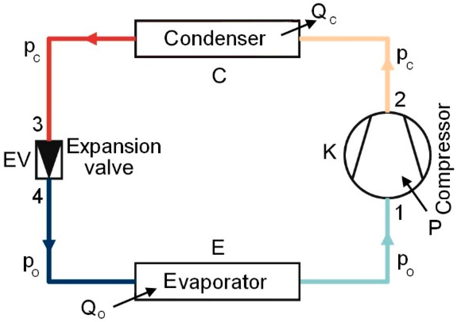
3.2.2. Heat Pump Systems

The HP is one of the most favourable HVAC systems to consider when integrating RES. The quantity of energy Eres absorbed by an HP that qualifies as RES must be determined using the following equation [71]:
E res = E U ( 1 1 SPF )
where EU is the useful thermal energy supplied by HP, and SPF is its seasonal performance factor.
Only HP with SPF > 1.15/η will be considered, where η is the total gross electricity output ratio to primary energy consumption for power generation. The average η for EU nations is 0.4, indicating that the minimum SPF should be 2.875.
An HP is based on a reverse Carnot cycle, which uses driving energy and generates a thermal effect. Any HP transfers energy ES from a low-temperature source ts to a high-temperature source tu while using driving energy ED.
A heat source may be
  • Air or a gas (exterior air, warm air, or hot gases);
  • Surface water, groundwater, geothermal, or hot waste water;
  • The ground, which has the advantage of being easily accessible.
The most popular HP systems are powered by electricity and have an electro-compressor. The working concept of an HP based on vapour compression is presented in Figure 7 [72].
A cycle of evaporation, compression, condensation, and expansion is required to raise low-temperature heat to above 38 °C and transport it indoors. A non-chlorofluoro- carbon refrigerant flows within the HP [73].
  • Energy efficiency. The implementation of an HP in a heating/cooling system depends on energy indices and economic analyses. In heating mode, the operating an HP is characterised by the coefficient of performance (COP), which is defined as the ratio of useable thermal energy Et to electricity consumption Eel:
COP = E S + E D E D = E t E e l
Seasonal coefficient of performance (COPseasonal), sometimes referred to as the SPF or yearly efficiency, is determined if, in Equation (3), both useable energy and spent energy over a season (year) are included.
The cooling performance is expressed by the energy efficiency ratio (EER), in Btu/h:
EER = 3.412 × COP
where 3.412 is the conversion factor between Watt and Btu/h. GSHP systems have heating COP values between 3 and 5.5 and cooling EER values between 10.5 and 20 [72].
  • Calculation of CO2 emissions. HPs powered by electrical energy derived from hydropower or renewable energy decrease GHG emissions, such as CO2, much more than HPs powered by electricity derived from coal, oil, or natural gas power plants.
If Et is defined as the yearly thermal energy delivered by HPs, then the yearly consumption of primary energy from HP electrical usage is given by:
E e l = E t SPF
The HP’s CO2 emissions during operation may be calculated as follows.
C CO 2 = g e l E e l
where gel is the electricity-specific CO2 emission factor. The average gel in Europe is 0.48 kg CO2/kWh, whereas, in Romania, it is 0.54 kg CO2/kWh [74].
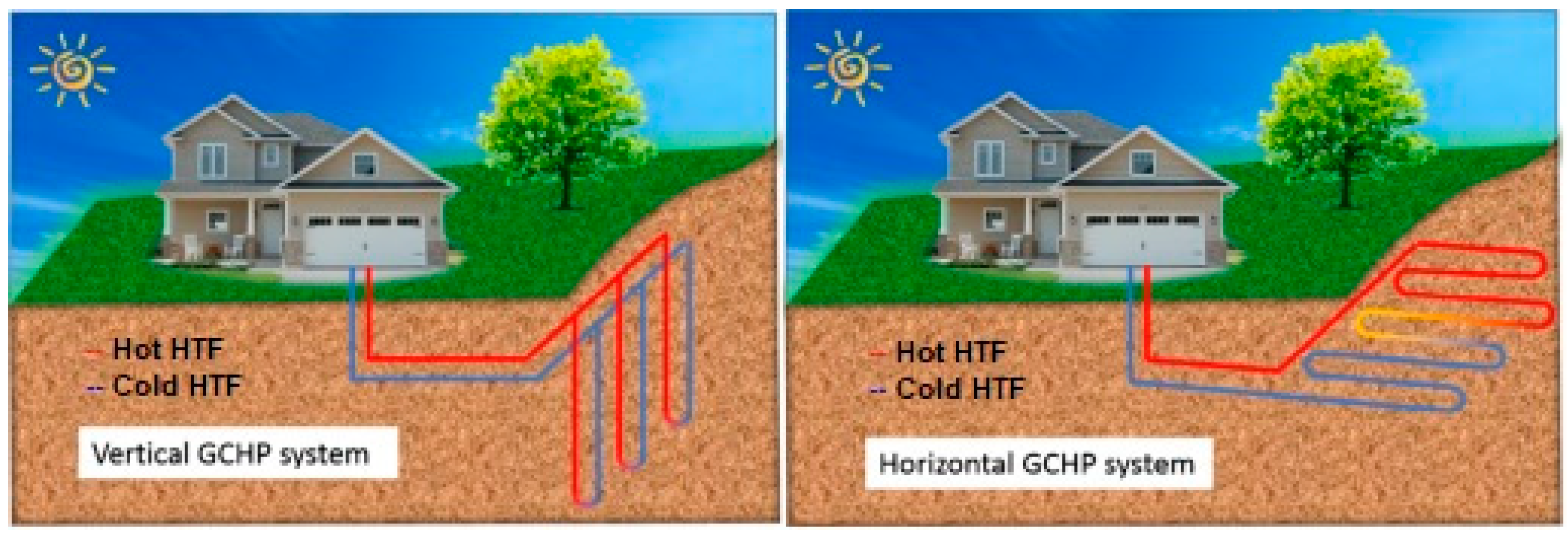
  • Heat pump types. The most prevalent method of HP categorisation is based on the heat source. There are two primary kinds of HPs: air-source HP (ASHP) and ground-source HP (GSHP), which includes water-source HP (WSHP) and ground-coupled HP (GCHP) systems.
ASHP operates with ambient heat and is used in bivalent heating systems for cooling, heat recovery, and DHW generation. ASHP is less efficient than GSHP if the outside temperature falls below −10 °C.
The WSHP system employs water as a heat source and either air or water to transfer heat to the air conditioner. Surface water HP (SWHP) and groundwater HP (GWHP) are two classifications for these systems. In an SWHP system, heat rejection/extraction is accomplished by moving working fluid via high-density polyethylene (HDPE) pipes placed at the proper depth in a lake, pond, or reservoir. This kind is confined to warmer areas for HP operation in the heating mode. A GWHP is an open-loop system that collects groundwater from a well and transports it to an HP (or an intermediary HX) for an energy source [75]. Except for minor installations, direct systems (where groundwater is pumped directly to the HP) are not advised.
A GCHP system is a closed-loop system [76,77,78,79] comprised of a reversible vapour-compression HP connected to a ground heat exchanger (GHE) (Figure 8) and a heat distribution subsystem.
A pump circulates a brine (antifreeze solution), as HTF, via the GHE (collector or borehole) and the HP. The GHEs frequently utilised in GCHP systems are composed of HDPE pipes. GHEs may be divided into two significant kinds based on their spatial arrangement: horizontal (0.8–1.8 m deep) and vertical (often 20–200 m deep) GHEs. Horizontal single-pipe GHEs consist of parallel pipes laid in trenches. Special GHEs, such as multiple pipes inserted in a single trench and spiral loops, were created to save the ground surface [80]. U-tubes and coaxial tubes are the two most prevalent configurations for vertical GHEs or borehole heat exchangers (BHEs) [81]. The annulus of a borehole is often backfilled with a specific substance (grout) that may prevent groundwater pollution.
It was shown [82] that GCHPs are the dominant form of direct geothermal energy use. Multi-depth geothermal systems use geothermal energy from various depths to produce energy for heating; heating and cooling; or heating, cooling, and power [83]. Figure 9 depicts a simple geothermal system with several depths [31]. Deep geothermal systems feed old buildings by a 3GDH network, medium-deep geothermal systems supply rehabilitated or new buildings via a 4GDH network, and shallow geothermal systems serve NZEB through a 5GDHC network. Multi-depth geothermal systems are appropriate for districts with varying heating and cooling needs, such as residential and administrative buildings.

3.2.3. A Brief Overview of Previous Works

An economic and environmental study [84] revealed that DH based on a vertical GCHP system for a university campus in Spain is preferable to the current fossil fuel-based system. Another research [85] demonstrated that horizontal and vertical GCHP systems are less economical than UK gas boilers.
According to [86], the thermal performance of the double U-tube arrangement is 30–90% greater than that of the single U-tube configuration. Horizontal GHEs were extensively studied and simulated using analytical and numerical models [87] and computational fluid dynamics (CFD) [88] to compare linear and spiral systems. The findings revealed that horizontal helical systems are the most energy-efficient.
Pratiwi and Trutnevyte [89] investigated the environmental impact of shallow and medium-deep systems for heating/cooling on a large scale, revealing that geothermal systems with depths of 350–1600 m coupled to disperse HPs have the most negligible environmental impact. The energy and economic performance of various deep coaxial closed-loop systems configurations were analysed [90].
In the last two decades, more researchers examined the performance and applications of solar-assisted HP (SAHP) and GSHP systems. These technologies may be used to generate the solar-assisted GSHP (SAGSHP) hybrid system [91]. Yuehong et al. [92] performed experiments on a SAGSHP system in which the heating mode alternates between an HP powered by solar energy and a vertical GCHP. Ozgener and Hepbasli [93] experimentally evaluated the efficiency of a SAGSHP greenhouse heating system with a vertical GHE. Zongwei et al. [94] also examined a SAGSHP heating system with latent heat TES. They asserted that the latent heat TES might enhance the solar fraction of the system, increasing the COPsys.
Recent research [95,96] addresses integrating TES technology into the distribution network to decrease the required peak capacity, enhance renewable penetration, or improve efficiency.

3.3. Hydraulic Energy

As the oldest kind of RES utilised by humans, hydraulic energy can be found in potential energy (water-free fall) and kinetic energy (water flow). During this century, the global need for electricity will increase dramatically due to population growth and improving living standards in developing nations.
Currently, when fossil fuel prices and environmental protection costs continue to rise, micro-hydropower plants are now winning the competition to provide electricity to isolated localities and objectives.
In recent years, the recovery of excessive hydraulic energy from DH networks, especially urban water networks using micro-hydropower technology, has been considered [97,98,99,100,101,102,103].
The network hydraulic regime is determined by water discharge, pressure, and the components’ hydraulic characteristics. Expanding a DHS involves increased water pressure at the heat source node, often necessitating pressure reductions at network nodes or main pipes. Traditionally, the only way to reduce pressure is to use pressure-reducing valves (PRVs), which release excess energy. This situation creates a possibility to recover energy, identified by analysing piezometric graphs, using micro-hydropower technology with pumps operating as a turbine (PATs). The electricity thus produced supplies the electricity grid. Piezometric graphs show the distribution of water pressure in the network for heat sources, pipes, and nodes, considering the geodetic profile and the network route.
PATs are micro-hydro turbines mounted in the urban water supply or heating systems in places where pressure adjustment is advantageous or necessary. PRVs and PATs are similarly exploited to maintain downstream pressure. Generally, a PRV is mounted in parallel with a PAT to bypass surplus discharges the turbine capacity and support the system’s operation during turbine maintenance [104]. Typical locations of PATs are directly downstream of DH substations or on the main pipe (Figure 10). The optimal locations of the PATs can be determined using optimisation models [100].
The installation of PATs in DHSs generates electricity, reduces water and heat losses in the system, minimises the impact on the environment, and eliminates the need for geological and hydro-geological studies of the site.

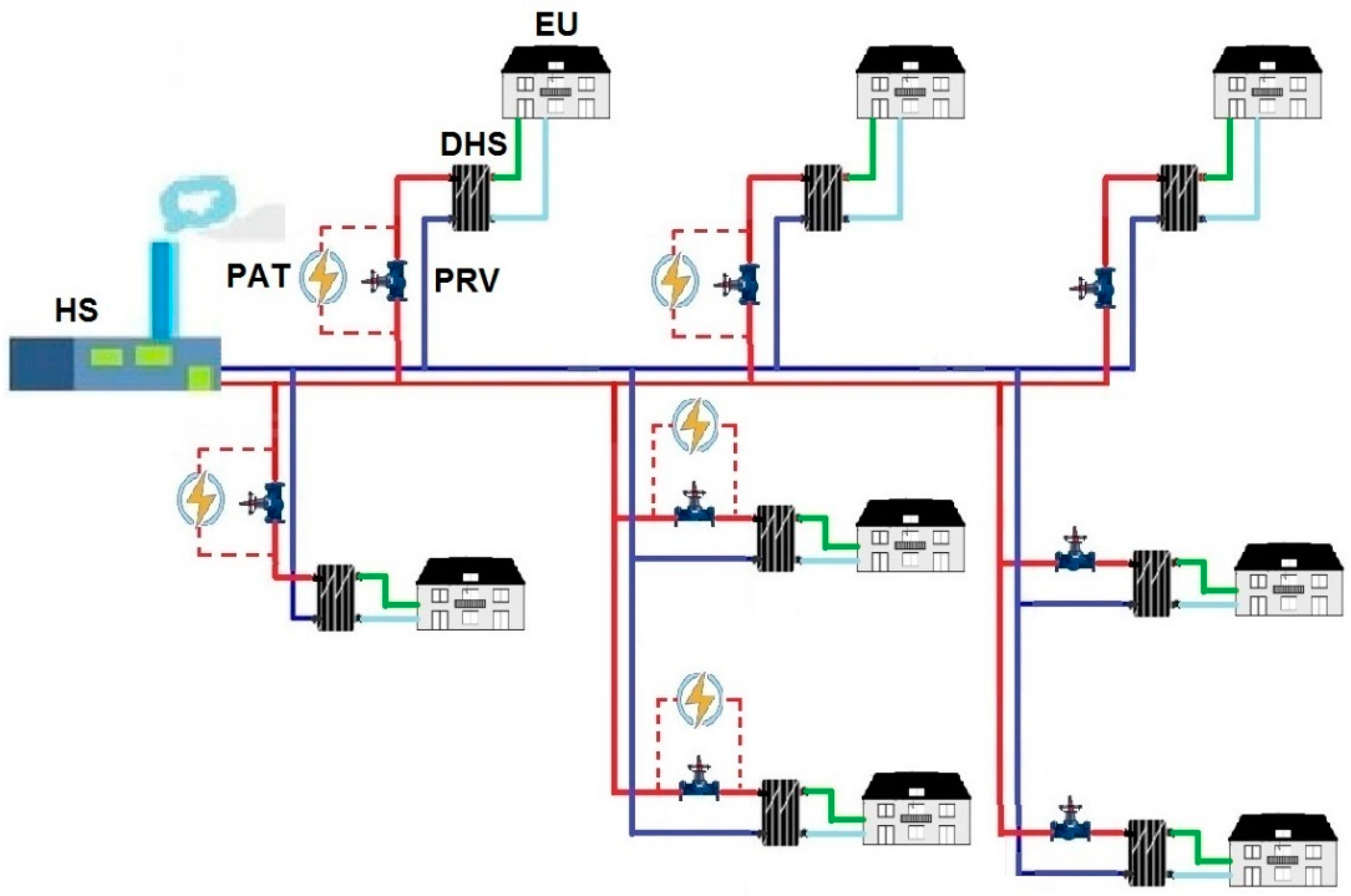
4. Interconnection between DH System and Power Grid

The interconnection of DHSs with electricity grids is essential with the increasing levels of variable renewable energy being introduced to the system, which can lead to grid instability.
Large-scale HPs were identified as an essential technology to utilise intermittent power production from RES by integrating the power and heating sectors. Implementing PV systems in buildings supplied by a DHS significantly reduces electricity purchased from the power grid. At the same time, the surplus of electricity produced by PV systems compared to the building’s consumption can be used to operate HPs that pump thermal energy into the thermal energy storage (TES) system. In this way, an interconnection of the thermal and electrical sectors can be achieved to increase the flexibility of the entire energy system.
Because RES is affected by a certain degree of uncertainty, such as the variation in PV solar energy produced in a unit of time (hour, day), it is recommended to use energy planning for power microgrids [105], as well as an electricity storage system (ESS) [106]. The introduction of ESSs implies a multi-period operational planning problem. Byrne et al. [107] examined the optimisation of ESS functioning in general and included considerations of stochastic optimisation techniques and solar energy integration applications.
In DH, the management term relates to maintenance, energy and economic management, system development, and modernisation. Weather data control, building consumption modelling, and DHS modelling yielded favourable outcomes in DH management [5]. Currently, preventative systems, automatic detection, and failure localisation through SCADA monitoring, GIS, and other tools are utilised to assure the network’s resilience. DH should stay up with technological, regulatory, and heat production process advancements. Typically, the creation of new local DH networks and the split of existing networks (decentralisation) are more lucrative than the extension of an existing network.

5. Examples of Integrating RES in a DHS

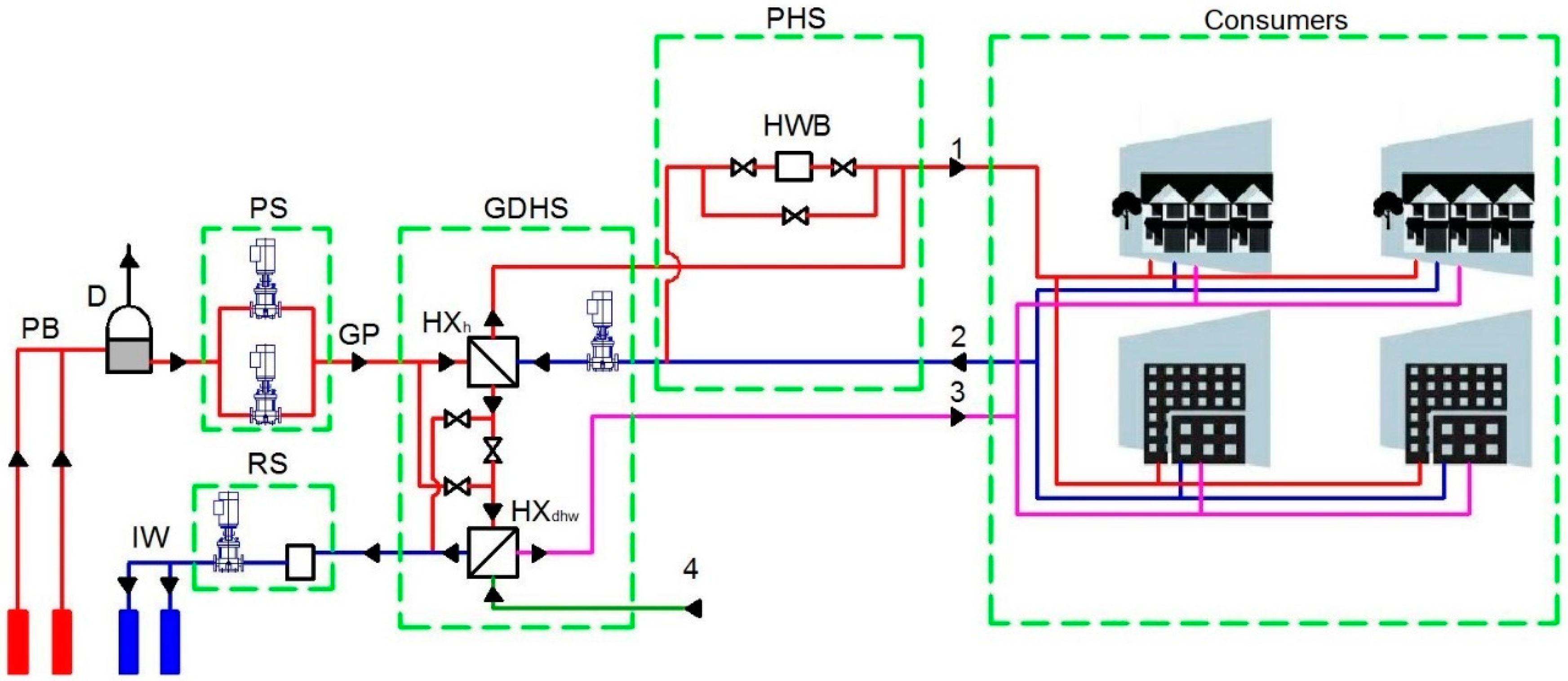
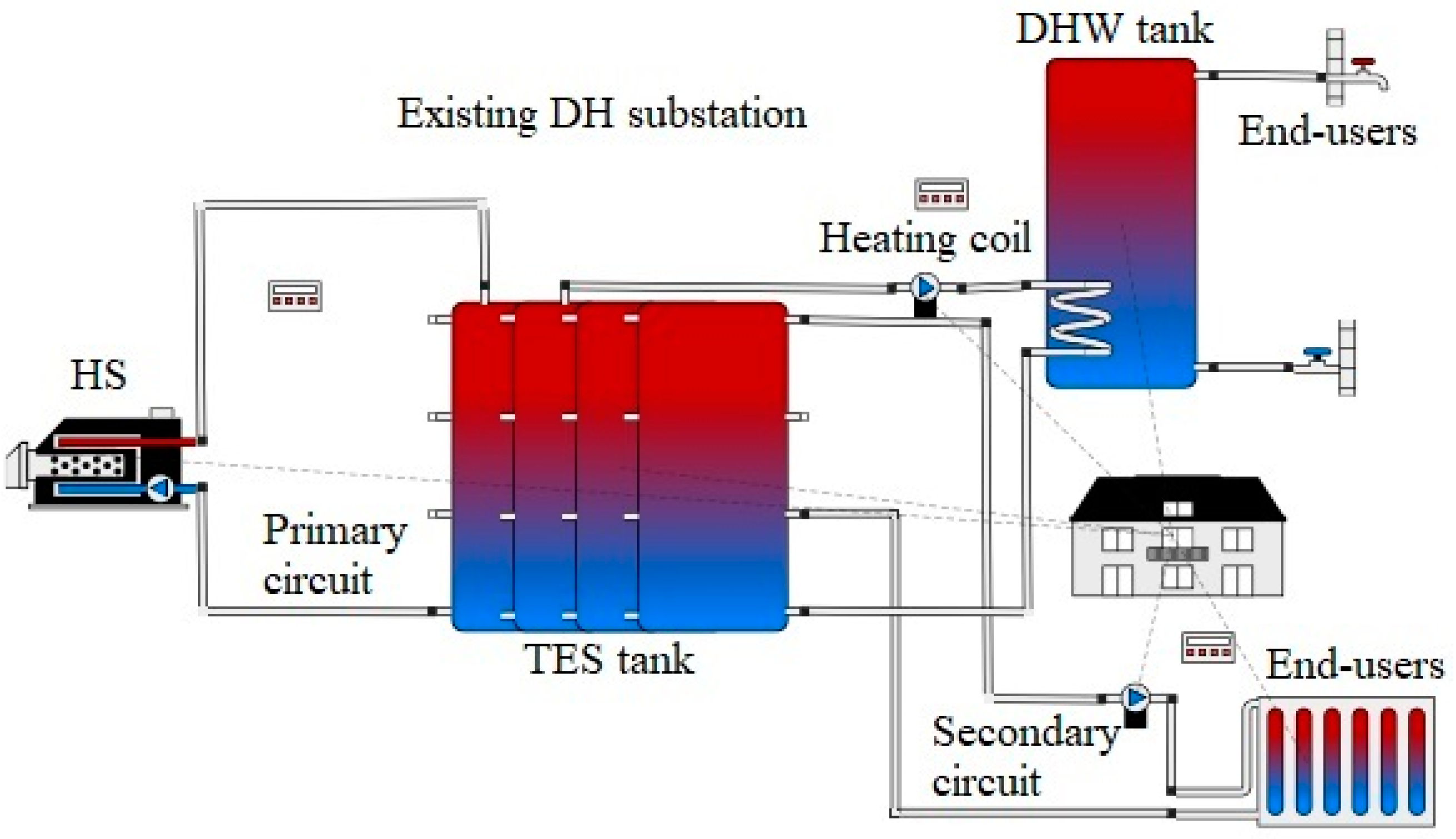
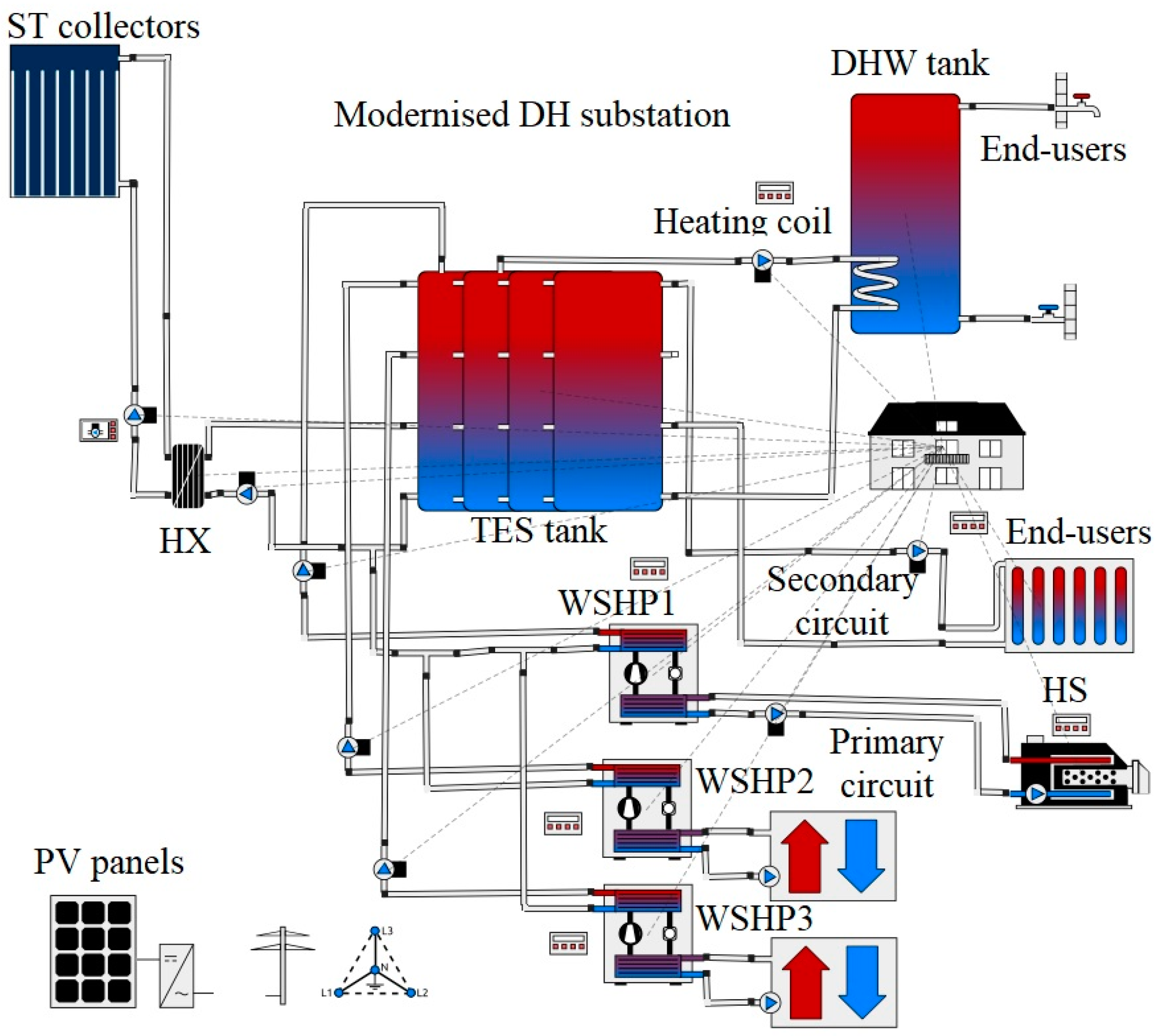
5.1. Integration of WSHP Systems in Cooperation with ST and PV Collectors and Reduction in Supply Temperature in a DHS of 3rd Generation Adapted to 4th Generation Case Study 1

In the last decade, many studies approached different aspects regarding potential enhancements of DHSs (geothermal DHSs, 4GDHSs, seasonal TES, optimisation of CHP plants) [8,9,14,61,108,109].
The ultimate objective of EU nations is to become independent of fossil fuels. RES technologies may be included in existing DHSs with minor adjustments requiring low temperatures and a network with minimal heat losses [110]. However, DHSs using only RES are uncommon. Due to the variable energy supply from RES, they generally mix traditional energy sources with different RES and energy storage. The possible connections of RES in DHSs are: (1) central mode, in which the RES provides heat to the primary heat source with sizeable seasonal heat storage, and (2) distributed mode, in which the RES are put in appropriate places and directly linked to the DHS.
One of the dimensions that could be taken into account by the DH is self-reliance, which consists in maximising the use of locally generated energy and minimising the import of energy from the external. Uncertainties associated with RES electricity generation and user electricity demand are described in [111]. Based on the forecasts made by a prosumer regarding the energy produced and consumed in a unit of time, correlated with the weather forecast, it is possible to determine the energy consumed or delivered to the power grid. The energy independence of a microgrid’s energy trading system is primarily influenced by the average proportion of the energy acquired from the national power grid to energy used by prosumers and may be evaluated using a new index [111].

5.1.1. Description of the Systems

Timisoara has a high potential for solar and geothermal energy in Romania [112,113], which may be used for thermal building needs (space heating, DHW generation). At present, DHS in Romania is transitioning from the second and third generation to the fourth generation and, specifically, the fifth generation. In the 3GDH system of the city of Timisoara, the primary circuit (transmission network) transports the high-temperature hot water, 115 °C in the supply pipe and 60 °C in the return pipe, from the HS to the zonal DH substations. In these substations, the thermal energy is transferred to the secondary circuit (distribution network) at a lower temperature of 70/50 °C, using plate HXs that supply the end-users. Transmission network pre-insulated steel pipes have diameters between 250 and 1000 mm, whereas distribution network pipes have sizes between 50 and 250 mm. The DHS utilises a dual-fuel heat source (fossil fuel with natural gas).
The existing “UMT” substation (Figure 11) is fed through pre-insulated steel pipes with a diameter of 150 mm, on a route with a length of 1500 m. This substation supplies heat and DHW to a district with ten thermal rehabilitated residential buildings in height regime GF + 4 floors, with a heat demand of 3.2 MW. The heating terminal units for end-users are water radiators, DHW temperature is 52 °C, and indoor air set-point temperature is 20 °C.
The transition from 3GDH to 4GDH systems necessitates a reduction in the primary circuit supply temperature from 110 °C to 30 °C and the return pipe temperature from 60 °C to 20 °C. For this purpose, a three-way solenoid valve was located in the branching area of the primary circuit. This valve feeds a modernised substation equipped with a SAWSHP system.
The low-temperature hot water (30 °C) from the primary circuit is introduced in a WSHP that produces a secondary heat carrier at a temperature of 58 °C, stored in a TES tank (Figure 12). Two other WSHPs that extract geothermal water from two drilled wells to the depth of 800 m, each with a discharge of 6.60 dm3/s, at a temperature of 40 °C [112], also produce secondary heat carriers at a temperature of 58 °C, stored in TES tank. EcoTouch 6900.5 Q Goliath type WSHPs operate with R-410A as a refrigerant and have a heating power of 1400 kW.
Additionally, there are 65 ST panels of type 24 vacuum tubes Viessmann Vitosol 300-TM 3.03 m2 with a total collector area of 299.6 m2 on the terrace of the modernised substation building. This solar panel field has 129 MWh/year of solar production. HTF flows through all components of ST panels, which is a combination of water and ethylene glycol (40% by volume). The solar energy collected by the PV array field is transmitted from the HTF to the TES tank via an HX. The hot water of 58 °C accumulated in the TES tank is transferred by the secondary circuit to the end-users for space heating and through a heating coil to the DHW tank. DHW produced in the DHW tank has a temperature of 52 °C, preventing Legionella bacteria formation in the plumbing system. The indoor air set-point temperature is the same, 20 °C.
In order to cover the electricity consumption of the three SWHPs, 2000 PV panels of the type AXIpremium XXL HC with a total capacity of 1090 kW, which produce 1160 MWh/year of AC with an energy efficiency of 72.3%, are installed on an area of 5160 m2 of the available terraces of the buildings supplied by DH station.
Integrating intelligent control techniques into the energy management of DH may result in optimum system management with considerable advantages over traditional control strategies [114]. Model predictive control (MPC) is a strategy that uses a dynamic model to anticipate system behaviour and optimise actions to obtain the optimal sequence of decisions [115,116]. Depending on the building’s energy needs, the strategy may decide to deliver the energy produced by renewable directly to the building or store it for future use. Almost all research publications describing the usage of MPC and TES in DH systems were published during the last years [114]. Consequently, this approach is just beginning to be investigated. Thieblemont et al. [117] emphasised how MPC considers time-of-use tariffs in the objective function for peak demand reduction in electricity-based systems. The controller thus charges most of the storage during low-price times and discharges it during high-price ones. Carli et al. [118] offered an innovative, robust MPC algorithm for microgrids with uncontrolled and controllable thermal and electrical loads, minimising the overall economic cost while meeting end-users comfort and energy requirements.

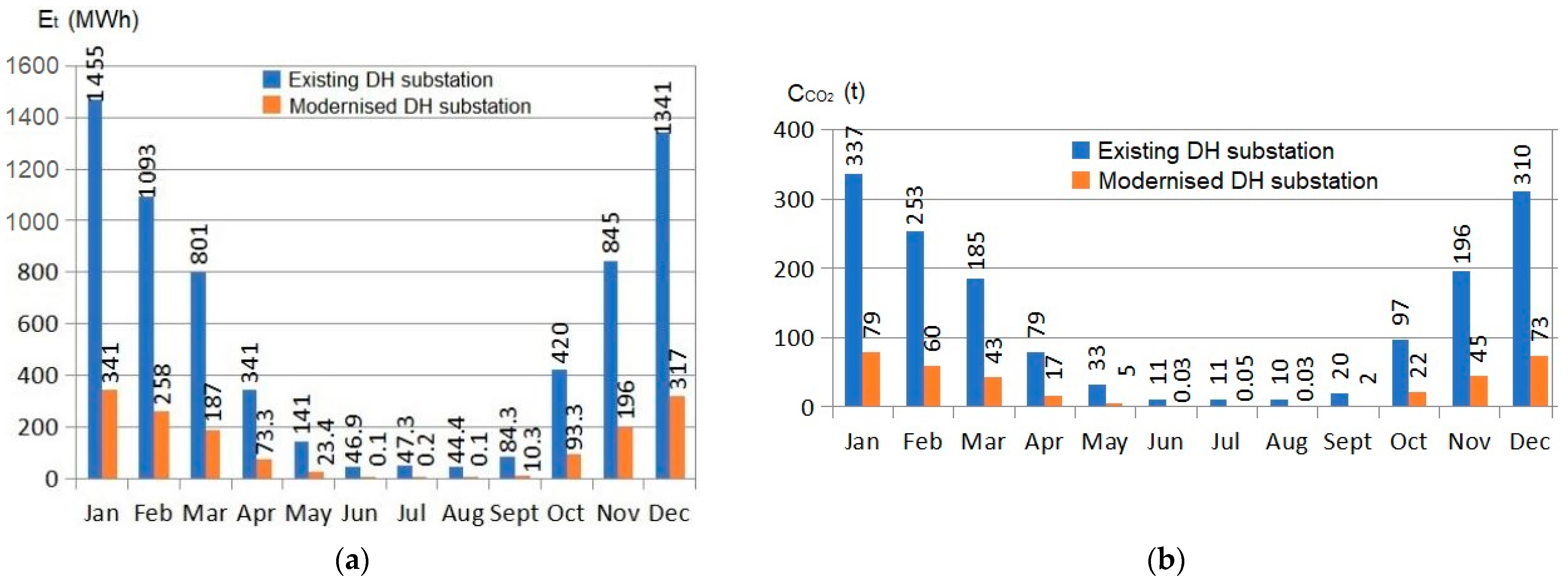
5.1.2. Simulation Results Utilising Polysun Software

Polysun [119] is the most effective program for planning, developing, and optimising complex energy systems for buildings and districts. All models are based on component catalog data (valves, pipes, ST and PV panels, HPs), meteorological data, building parameters, space heating demand, and DHW demand.
Polysun was used to simulate the thermal energy (Et) needed to satisfy heating and DHW requirements for the analysed district and the electricity generated by PV panels (Eel,p), which compensates for the electricity used by the 3 WSHPs. Meteonorm database [120] provided the following weather information for the city of Timisoara, whose latitude and longitude are 45°47′37″ and 21°15′44″, respectively: average outdoor temperature 11.8 °C; global irradiation 1301 kWh/m2; and diffuse irradiation 639 kWh/m2.
Figure 13 illustrates the yearly variation in DHS’s thermal energy consumption (Et) and CO2 emissions ( C CO 2 ) based on simulation findings. The thermal energy extracted from the DHS is utilised for space heating and DHW by the existing or modernised substation. CO2 emissions are only produced when fossil fuels and natural gas are used in HS. The HPs have zero CO2 emissions since the power they use is generated by PV panels. Table 6 presents the performance of the three WSHP systems, while Table 7 summarises the main simulation findings.
Figure 13 and Table 7 demonstrate, as a result of the simulation, that the modernised substation reduced its thermal energy consumption from DHS by 75%, or 4535 MWh/year, and its CO2 emissions by 77%, or 1195 t/year. Moreover, simulation results showed that the modernised system reduced heat losses ( Q ˙ h l ) in the transmission network by 90%, from 420 MWh/year to 39 MWh/year, and generated 1160 MWh/year electricity. In addition, the incorporation of RES results in a SPFsys value of 2.30 for the modernised system compared to only 0.89 for the existing system. The solar fraction for heating is 1.0%, and for DHW, it is 38.8%.

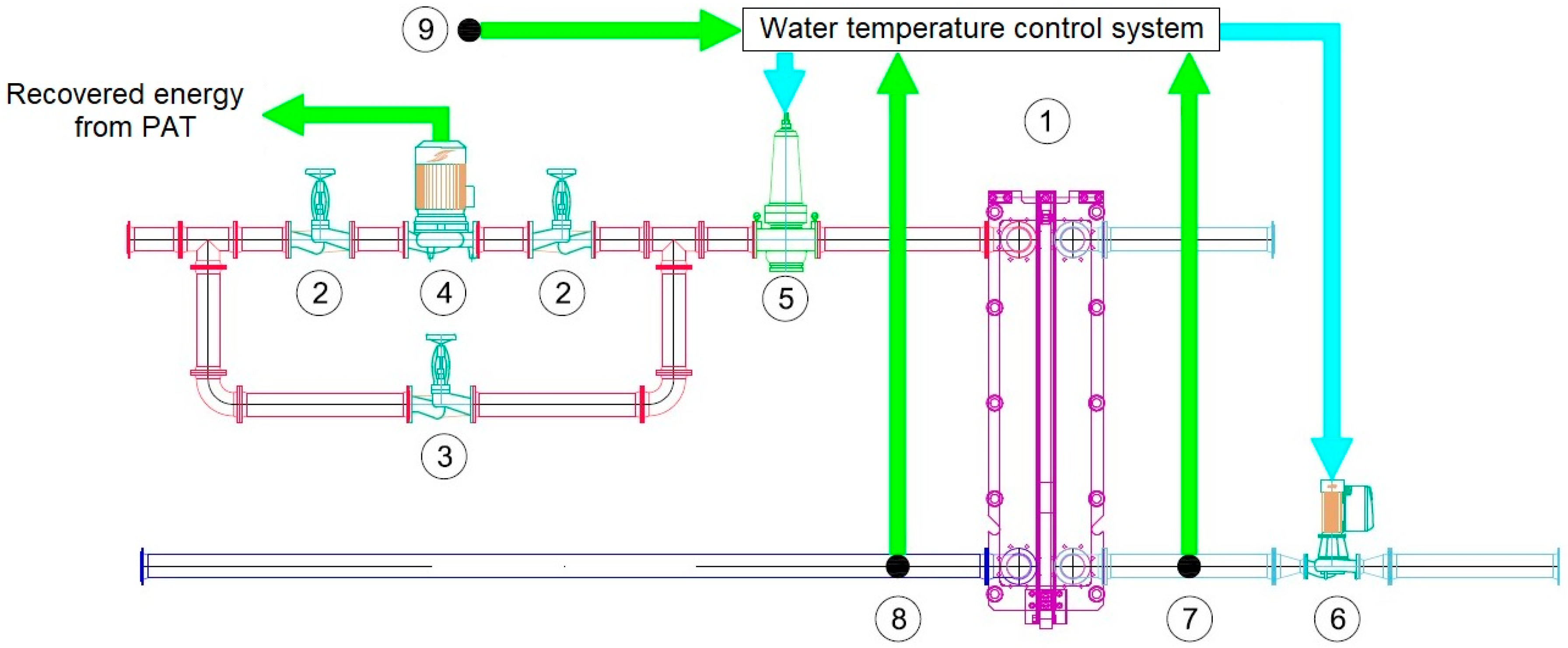
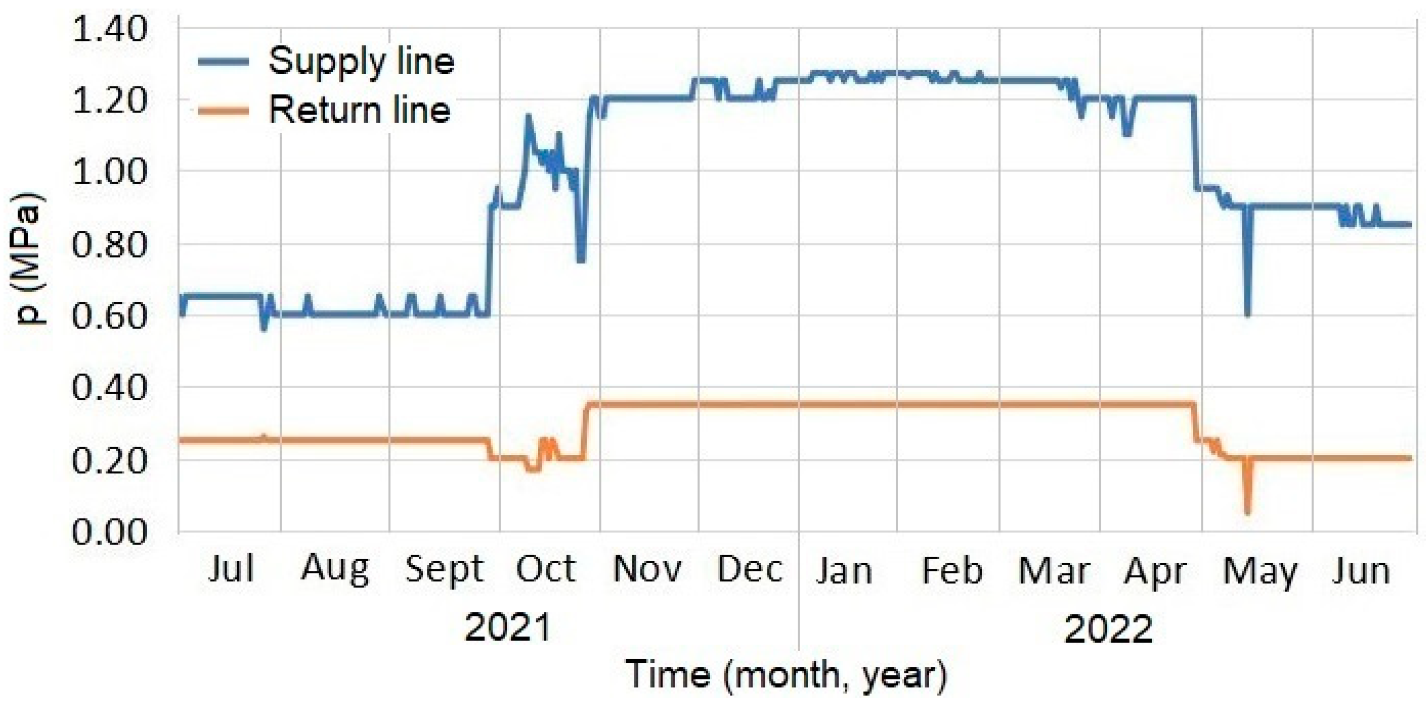
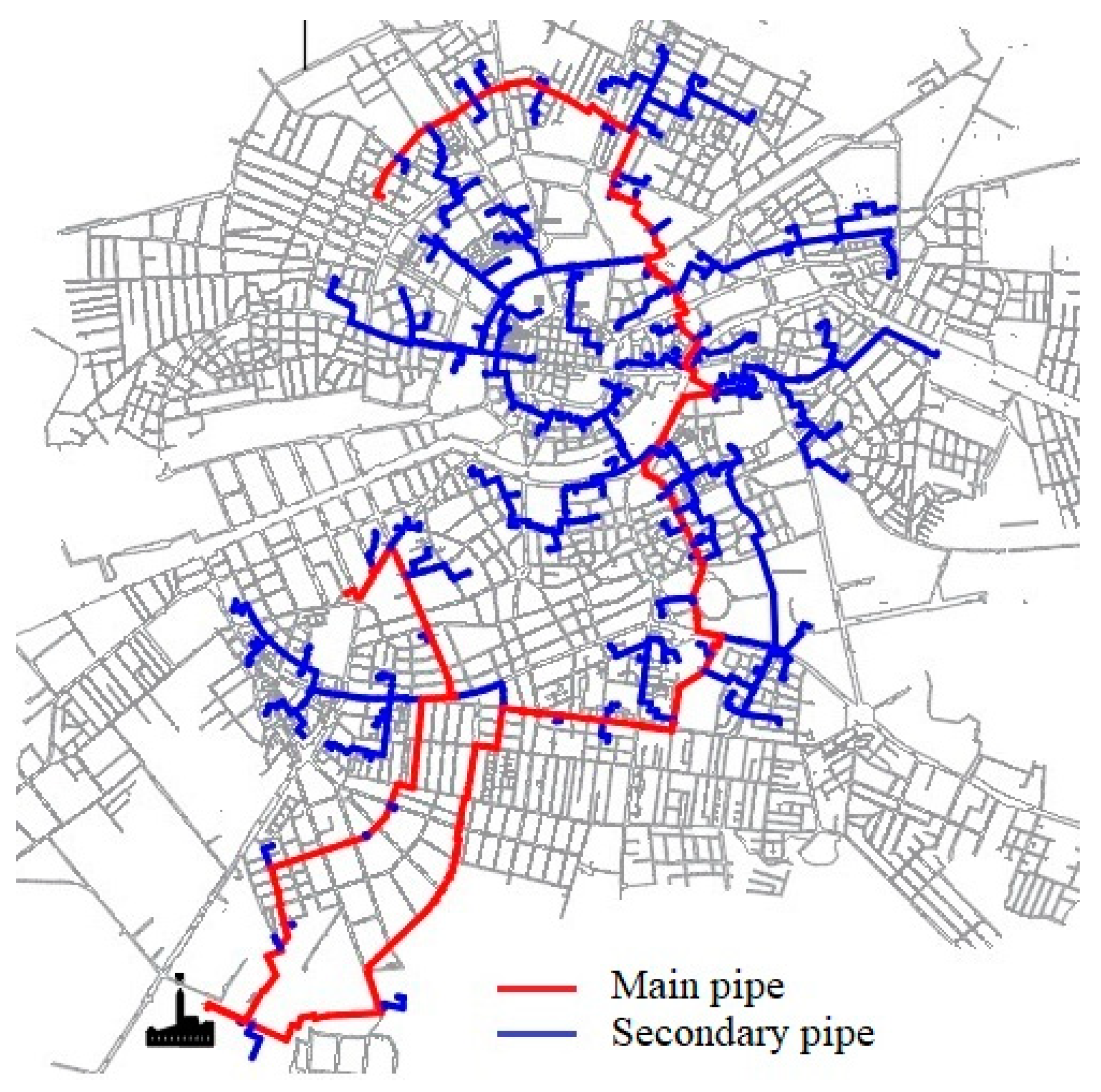
5.2. Installation of the Micro Hydro-Turbines in a 3GDH System Case Study 2

PRVs are often placed at DH substations, called nodes, to regulate the supply discharge and pressure (quantitative control) of the substation to limit the excess available pressures of hot water in the DH network of the city of Timisoara.
This study demonstrates the feasibility of adding pumps operating as micro hydro-turbines (PATs) into the heat transmission network in Timisoara (Figure 14) to recover a significant portion of the hydraulic energy often dissipated by PRVs. This network comprises two 350–1000 mm-diameter water mains. The network length is estimated to be 83 km, with 4000 heated buildings and total heat demand of 339 MW. The difference in height between the network’s highest and lowest points is 3 m. During the heating season, the average water discharge delivered by the heat source is 5273 m3/h.
On each connection of the DH substation, it is feasible to replace an existing PRV with a specific device consisting of a PAT coupled with an electric generator (Figure 15). The PATs may be installed at nodes where the available pressure exceeds the required pressure of 0.25 MPa [103] in the DH substation.
The following equation gives the excess available pressure Δp in N/m2 at a node:
Δ p = p p r e q
where p is the available pressure at a node, in N/m2, and preq is the required pressure, in N/m2.
The discharge demands Q, in m3/s, and available pressures p, in N/m2, at nodes are acquired from the COLTERM Heating Company’s measurements. Figure 16 and Figure 17 depict the variation in transmission network water characteristics over one year. The surplus available pressure of hot water may be turned into the power P, in kW, of micro hydro-turbines positioned at nodes according to the following equation:
P = Q Δ p   η 1000
where Q is the flow rate, in m3/s, Δp is the available pressure, in N/m2, and η is the overall micro-turbine efficiency, which is equal to the product of the individual efficiencies of its components (turbine and generator), assumed to be 60%.
Only nodes producing at least 1 kW of electrical power are evaluated, considering the solution’s viability and the economics of the needed equipment. The transmission network in the DHS of Timisoara supplies approximately 112 substations, but only 95 exceed the minimum power needs during the heating season (15 October–15 April) 2020/2021. Table 8 lists the node’s number and total electric power produced by PATs based on a range of recovered power.
Table 8 indicates that 491 kW of electric power may be produced from the network’s excess pressure during the heating season (4000 h), which corresponds to the electrical energy of 1964 MWh/season. Using energy on-site (e.g., through pumps or HXs) decreases the electricity consumption at network nodes with DH substations. Implementation of this system is facilitated by the absence of required changes to the electrical installation and network interventions by the power provider.

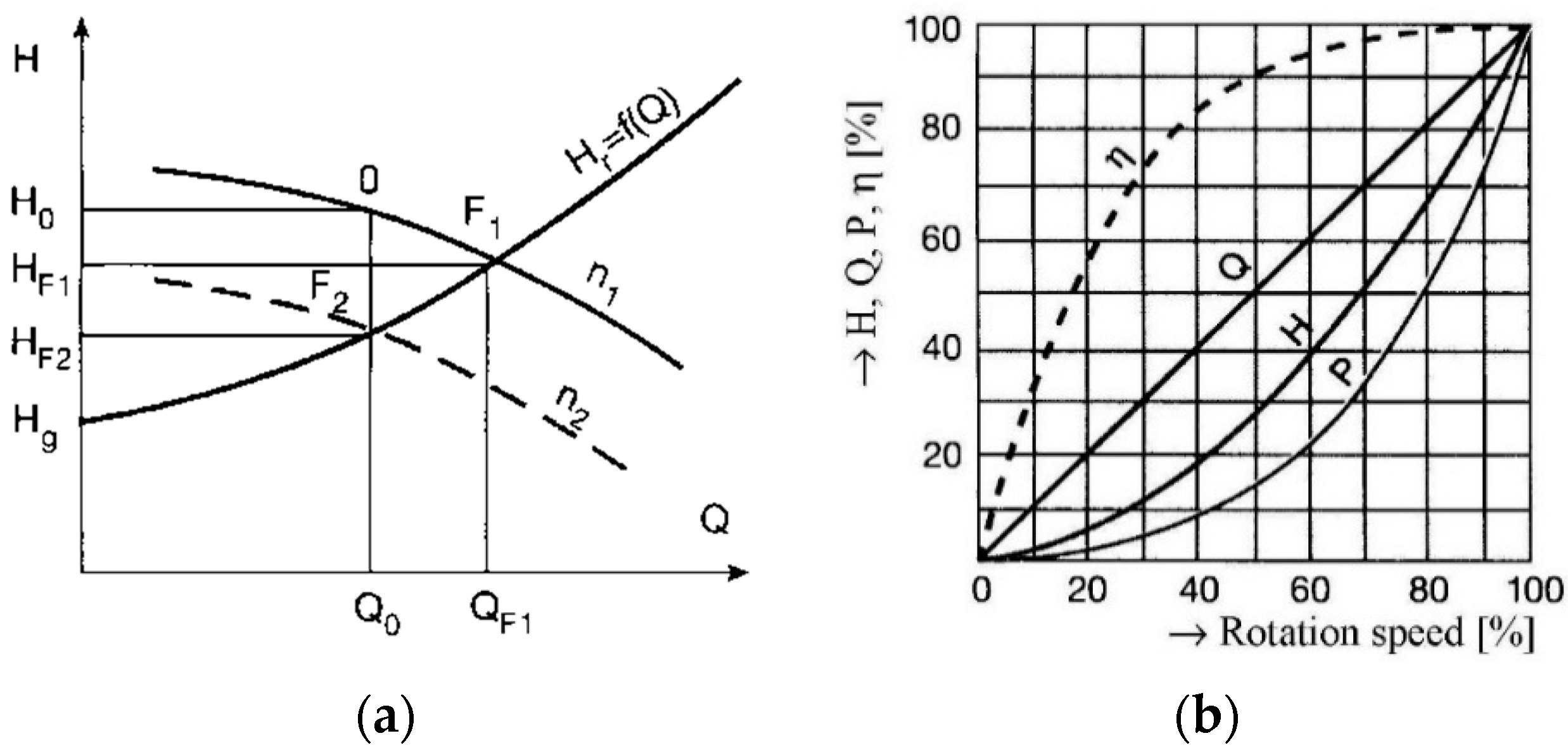
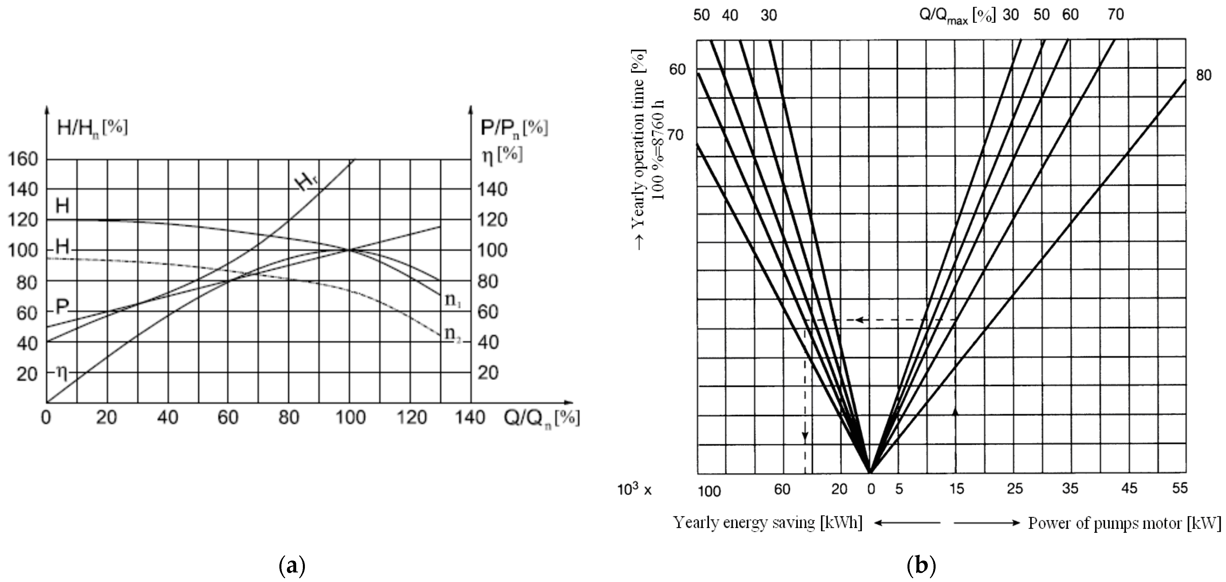
6. Improving Energy Efficiency of Water Pumping in Heating Stations

In an HS, the pumps circulate the heat carrier between the heat source and the consumers. Typically, variable discharge pumping applications use a throttle valve, bypass pipe, and variable rotation speed to achieve the required flow rate.
This section explains pump control in HSs and analyses the energy performance of flow control techniques through a case study in Timisoara.

6.1. A Brief Review of Previous Works

The primary objective of operating a DHS is to satisfy the heat requirements of end-users based on exterior climatic data. Consequently, the system is outfitted with a regulation mechanism that may be qualitative, quantitative, or a combination of the two. Fixed-speed pumps (FSPs) or variable-speed pumps (VSPs) are capable of quantitative regulation (changing the discharge during operation while maintaining constant hot water parameters). An attractive solution to lower the pump running cost is employing VSPs instead of FSPs.
The power P, in kW, absorbed by a pump is expressed as follows [121]:
P = γ Q H 1000 η = 3600 w p Q
where γ is the water-specific weight, in N/m3; Q is the pump’s discharge, in m3/s; H is the pump head for the operating point, in m; η is the pump’s global efficiency; and wp = 0.00272Hp/η is the specific pumping energy, in kWh/m3.
If the pump used in an HS is a centrifugal FSP, the operating point must displace along the head–discharge (H-Q) curve that corresponds to the fixed nominal speed. Changing the water flow rate in a pipe network with an FSP may be accomplished in two ways: by bypassing a portion of the water discharge or by producing a supplementary pressure loss with a control valve [122].
VSPs are the most effective way to produce a variable water discharge. By modifying the pump curve H (at various rotation speeds n1 and n2) on the fixed system curve, Hr allows flow control (Figure 18a) [123]. Pipeline curve Hr begins at (0, Hg), where Hg represents the geodetic elevation. The operating point F2 correlates to the lower pump head HF2.
The affinity laws [124] describe the expressions of the pump characteristics (Q, H, P) working at various speeds (n1, n2):
Q 1 Q 2 = n 1 n 2 ;   H 1 H 2 = ( n 1 n 2 ) 2 ;   P 1 P 2 = ( n 1 n 2 ) 3
The approximation incorporated into the relationship between power and rotation speed indicates that efficiency remains constant for speeds n1 and n2, i.e., the efficiency curve only moves to the left if the speed decreases. An analytical relationship for estimating the efficiency η of VSPs while modifying their operating point is provided by [121]:
η 2 = 1 ( 1 η 1 ) ( n 1 n 2 ) 0.1
Figure 18b demonstrates that a 20% drop in pump speed will result in a 50% reduction in power demand, assuming unchanged pump efficiency. Consequently, it is possible to minimise pumping energy consumption using variable-speed drives (VSDs), also referred to as variable frequency drives (VFDs).
Suppose several pumps are to work in parallel [125,126]. In that case, the rotation speed of a single pump may be adjusted (while the other pumps continue to function at their standard speed and flow rate), and the VFD automatically connects the other pumps. In order to link the pumped discharge with the heat requirement and to maintain the needed pressure while utilising the least amount of energy, an automatic speed control mechanism for pumps [123] was developed.
VSD features an induction-type motor that can adjust the pump’s speed based on system conditions. In variable drive systems, the VFD generates additional motor losses. Consequently, the general calculation equation for the efficiency η of a VSP system is following [127]:
η = η m η VFD η p
where ηm is motor efficiency; ηVFD is the efficiency of VSD; ηp is pump efficiency.

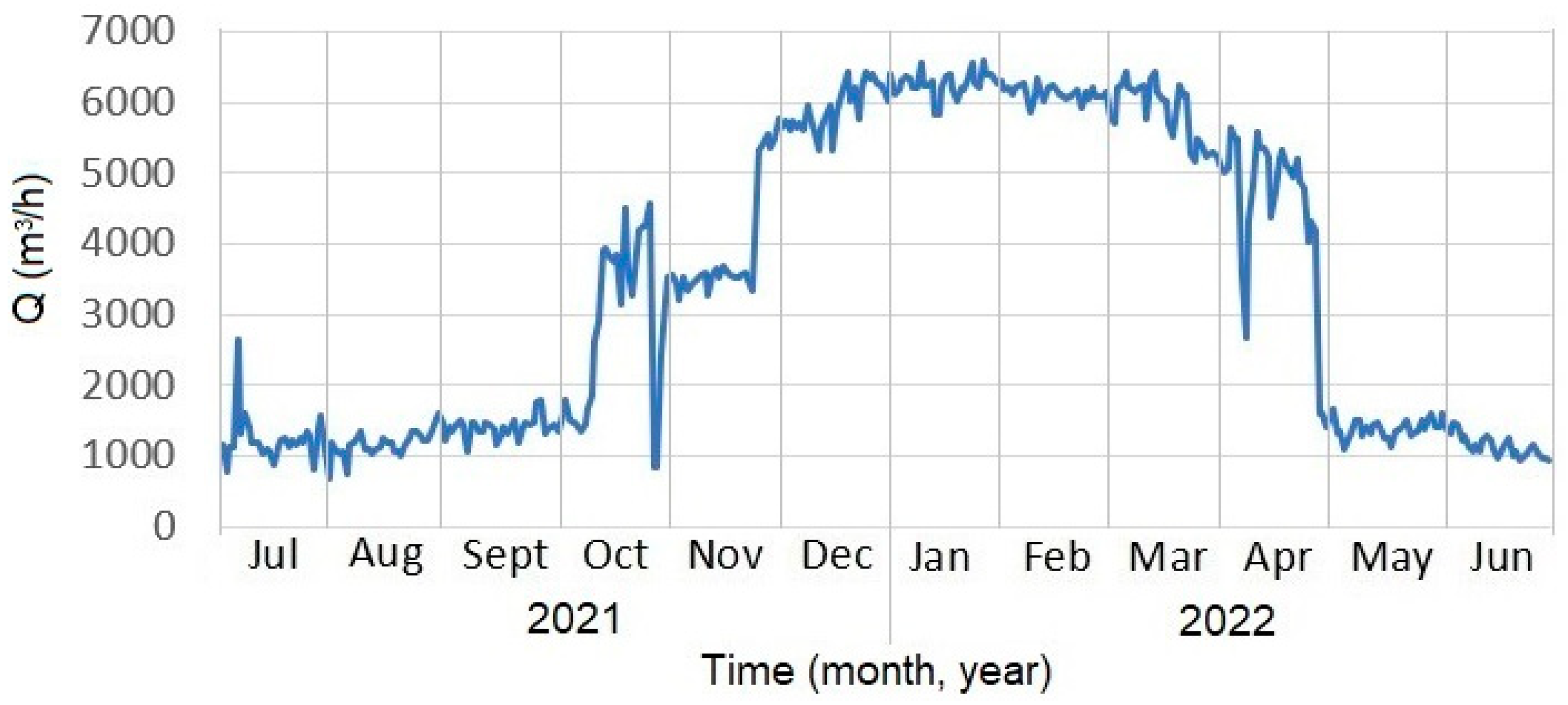
6.2. Evaluation of Energy Savings via Variable-Speed Drives Case Study 3

It was deemed a HS pump in Timisoara based on the following characteristics: TD 500-400-750 type; Q = 3150 m3/h; and H = 70 m. The following motor features were present: MIB-X 710Y type; 800 kW power; 94 A rated current; 6000 V voltage; 995 rpm rotating speed; cosφ = 0.87; 6000 kg mass.
In April 2015, a month with significant changes in hot water output, hourly observations were performed for 18 days. The heat demand was adjusted during this period by regulating the hot water discharge while maintaining a constant hot water temperature. The needed power was estimated hourly for two regulation methods: throttle control valve and variable-speed drive.
The heat demand depends on the outdoor air temperature and the return pipe temperature. The operational discharge of the pump was lower than the design discharge. It was necessary to shut the pump outlet valve to accomplish the required flow rate, as specified by the chart control. Thus, lowering the water output raises the pumping head above that predicted by the characteristic curves at the same discharge.
The characteristic curves H, P, and η are shown as functions of Q in Figure 19a for throttle valve control; the consumed power per hour was computed utilising Equations (10) and (11), providing the power consumed by the electric motor with a frequency converter:
P 2 = P 1   ( Q 2 Q 1 ) 3
where P1 is the power consumed by FSP at the operating point Q1 = 3150 m3/h, H1 = 70 m.
Table 9 exposes the outcomes of the comparative energy analysis of the two regulating techniques. Compared to the throttle control valve technique, the VFD’s speed control method resulted in roughly 38% energy savings.
Figure 19b shows the calculation way of energy savings using VSPs based on the consumed power, Q/Qmax ratio, and annual operating duration. Consequently, a 15 kW motor with an operating flow rate of 70% of the rated value and an operating duration of 5300 h/year (60%) would save 43 MWh of electrical energy.

7. Conclusions

This survey assists in comprehending the efficient integration of RES with a storage strategy in a 4GDH system. The study’s principal results are as follows:
  • The significant reason to use a DHS is its environmental benefit, and the fundamental advantage of RES is that it can be utilised with traditional fuels to build hybrid systems with higher performance (high energy efficiency, low CO2 emissions);
  • Although low-temperature DHS would allow more low-grade heat to enter the supply, decentralised HPs are needed to raise the temperature before it enters the buildings;
  • Most HPs installed in regions with warmer climates are air-source, while most HPs placed in regions with colder climates are ground-source. GSHPs have a COP between 3 and 5.5. They may retain high efficiency even at medium water temperatures in the radiator, making them an excellent option for modernising buildings without replacing the old heating terminal units. The SAGSHP hybrid system is comprised of two promising technologies that may be included in DHSs to reduce CO2 emissions;
  • Geothermal and DH technologies need more research to cut prices and boost market competitiveness. The best ratio between building rehabilitation procedures and the incorporation of geothermal energy into a multi-depth system must be investigated;
  • By integrating SAWSHP systems and reducing the supply temperature from 110 °C to 30 °C in DHS, which supplies the radiators to consumers in a district of Timisoara city in a 58/40 °C temperature regime and produces DHW at 52 °C, a thermal energy savings of 75%, a reduction in heat losses on the transmission network of 90%, and a reduction in CO2 emissions of 77% were achieved. Additionally, installed PV panels provide 1160 MWh/year of electricity utilised to balance the energy requirement of HP systems. Thus, the system’s energy efficiency (SPFsys) was enhanced by 2.30. For a second case study of the city of Timisoara, it was shown that excess energy from the DH network could be recovered using micro hydro-turbines (PATs) to produce 491 MW of electricity at an overall efficiency of 60%;
  • The ability to use power produced from surplus hydraulic energy in the network on-site (e.g., by HX pumps or HPs) decreases the electrical energy consumption of network nodes with DH substations;
  • Discharge regulation using VSPs is an attractive way of pumping water in DH plants, as it ensures a correlation between heat demand and water flow, resulting in up to 35% energy savings. Additionally, the excessive pressure levels that might result in equipment operating problems are prevented;
  • In the future decades, new systems should be constructed using 5GDHC technology, and current systems should be rehabilitated or upgraded through new technologies towards environmentally sustainable hybrid systems with improved performance. Due to the bidirectional energy flows, a challenging task is modelling the optimal control of 5GDHC. Advanced controllers must account for uncertainties such as meteorological conditions, renewable energy production, and flexible consumer behaviour in DHS. Additionally, investment in research, development, and innovation in the DH field is essential to increase RES integration efficiency.

Author Contributions

Conceptualisation, I.S.; methodology, I.S.; software, M.M.; validation, I.S., M.M. and D.M.; investigation, M.M. and D.M.; writing—original draft preparation, D.M.; writing—review and editing, I.S.; supervision, I.S. All authors have read and agreed to the published version of the manuscript.

Funding

This research received no external funding.

Conflicts of Interest

The authors declare no conflict of interest.

References

  1. Anisimova, N. The capability to reduce primary energy demand in EU housing. Energy Build. 2011, 43, 2747–2751. [Google Scholar] [CrossRef]
  2. IEA. Energy Technology Perspectives 2016; International Energy Agency: Paris, France, 2016.
  3. Allard, F.; Seppänen, O. European actions to improve energy efficiency of buildings. REHVA J. 2008, 45, 10–20. [Google Scholar]
  4. EP. Directive 2010/31/EU on the Energy Performance of Buildings; European Parliament: Strasbourg, France, 2010.
  5. Sarbu, I.; Marza, M.; Crasmareanu, E. A review of modelling and optimisation techniques for district heating systems. Int. J. Energy Res. 2019, 43, 6572–6598. [Google Scholar] [CrossRef]
  6. European Association of District Heating and Cooling “Euroheat and Power”. District Heating and Cooling—Country by Country 2015 Survey; European Association of District Heating and Cooling: Brussels, Belgium, 2015. [Google Scholar]
  7. MRDPA; ME. Report on the Assessment of the National Potential to Implement High-Efficiency Cogeneration and Efficient District Heating And Cooling; Ministry of Regional Development and Public Administration; Ministry of Energy: Bucharest, Romania, 2015.
  8. Vallios, I.; Tsoutsos, T.; Papadakis, G. Design of biomass district heating systems. Biomass Bioenergy 2009, 33, 659–678. [Google Scholar] [CrossRef]
  9. Rezaie, B.; Rosen, M.A. District heating and cooling: Review of technology and potential enhancements. Appl. Energy 2012, 93, 2–10. [Google Scholar] [CrossRef]
  10. Hepbasli, A. A review on energetic, exergetic and exergoeconomic aspects of geothermal district heating systems (GDHSs). Energy Convers. Manag. 2010, 51, 2041–2061. [Google Scholar] [CrossRef]
  11. EC. Communication from the Commission to the European Parliament, the Council, the European Economic and Social Committee and the Committee of the Regions on an EU STRATEGY for Heating and Cooling; Technical Report; European Commission: Brussels, Belgium, 2016.
  12. ASHRAE Handbook. HVAC Systems and Equipment; American Society of Heating, Refrigerating and Air Conditioning Engineers: Atlanta, GA, USA, 2016. [Google Scholar]
  13. Frederiksen, S.; Werner, S. District Heating and Cooling; Studentlitteratur: Lund, Sweden, 2013. [Google Scholar]
  14. Lund, H.; Werner, S.; Wiltshire, R.; Svendsen, S.; Thorsen, J.E.; Hvelplund, F.; Mathiesen, B.V. 4th generation district heating (4GDH): Integrating smart thermal grids into future sustainable energy systems. Energy 2014, 68, 1–11. [Google Scholar] [CrossRef]
  15. Buffa, S.; Cozzini, M.; D’Antoni, M.; Baratieri, M.; Fedrizzi, R. 5th generation district heating and cooling systems: A review of existing cases in Europe. Renew. Sustain. Energy Rev. 2019, 104, 504–522. [Google Scholar] [CrossRef]
  16. Dalla Rosa, A.; Li, H.; Svendsen, S. Method for optimal design of pipes for low-energy district heating, with focus on heat losses. Energy 2011, 36, 2407–2418. [Google Scholar] [CrossRef]
  17. Srinivas, T.; Reddy, B.V. Comparative studies of augmentation in combined cycle power plants. Int. J. Energy Res. 2013, 38, 1201–1213. [Google Scholar] [CrossRef]
  18. Fang, H.; Xia, J.; Jiang, Y. Key issues and solutions in a district heating system using low-grade industrial waste heat. Energy 2015, 86, 589–602. [Google Scholar] [CrossRef]
  19. Chasapis, D.; Drosou, V.; Papamechael, I.; Aidonis, A.; Blanchard, R. Monitoring and operational results of a hybrid solar-biomass heating system. Renew. Energy 2008, 33, 1759–1767. [Google Scholar] [CrossRef]
  20. Mock, J.E.; Tester, J.W.; Wright, M.P. Geothermal energy from the Earth: Its potential impact as an environmentally sustainable resource. Annu. Rev. Energy Environ. 1997, 22, 305–356. [Google Scholar] [CrossRef]
  21. Cooper, S.J.G.; Hammond, G.P.; Norman, J.B. Potential for use of heat rejected from industry in district heating networks, GB perspective. J. Energy Inst. 2016, 89, 57–69. [Google Scholar] [CrossRef]
  22. Eriksson, M.; Vamling, L. Future use of heat pumps in Swedish district heating systems: Short- and long-term impact of policy instruments and planned investments. Appl. Energy 2007, 84, 1240–1257. [Google Scholar] [CrossRef]
  23. Ozgener, L. Coefficient of performance (COP) analysis of geothermal district heating systems (GDHSs): Salihli GDHS case study. Renew. Sustain. Energy Rev. 2012, 16, 1330–1334. [Google Scholar] [CrossRef]
  24. Werner, S. International review of district heating and cooling. Energy 2017, 137, 617–631. [Google Scholar] [CrossRef]
  25. Dalenbäck, J.O. Solar district heating and cooling. Euroheat Power 2013, 10, 26–29. [Google Scholar]
  26. Sarbu, I.; Sebarchievici, C. Solar Heating and Cooling Systems: Fundamentals, Experiments and Applications; Elsevier: Oxford, UK, 2017. [Google Scholar]
  27. Jie, P.; Tian, Z.; Yuan, S.; Zhu, N. Modeling the dynamic characteristics of a district heating network. Energy 2012, 39, 126–134. [Google Scholar] [CrossRef]
  28. Lund, R.; Mohammadi, S. Choice of insulation standard for pipe networks in 4th generation district heating systems. Appl. Therm. Eng. 2016, 98, 256–264. [Google Scholar] [CrossRef]
  29. Zvingilaite, E.; Ommen, T.; Elmegaard, B.; Franck, M.L. Low temperature DH consumer unit with micro heat pump for DHW preparation. In Proceedings of the 13th International Symposium on District Heating and Cooling, Copenhagen, Denmark, 3–4 September 2012. [Google Scholar]
  30. Østergaard, D.S.; Svendsen, S. Experience from a practical test of low-temperature district heating for space heating in five Danish single-family houses from the 1930s. Energy 2018, 159, 569–578. [Google Scholar] [CrossRef]
  31. Romanov, D.; Leiss, B. Geothermal energy at different depths for district heating and cooling of existing and future building stock. Renew. Sustain. Energy Rev. 2022, 167, 112727. [Google Scholar] [CrossRef]
  32. Sarbu, I. Advances in Building Services Engineering: Studies, Researches and Applications; Springer: Cham, Switzerland, 2021. [Google Scholar]
  33. ASHRAE Handbook. Fundamentals; American Society of Heating, Refrigerating and Air-Conditioning Engineers: Atlanta, GA, USA, 2021. [Google Scholar]
  34. Zirngib, J. Standardization activities for heat pumps. REHVA J. 2009, 46, 24–29. [Google Scholar]
  35. Crawley, D.B.; Lawrie, L.K.; Winkelmann, F.C.; Buhl, W.F.; Huang, Y.J.; Pedersen, C.O. EnergyPlus: Creating a new-generation building energy simulation program. Energy Build. 2001, 33, 319–331. [Google Scholar] [CrossRef]
  36. Klein, S.A.; Beckman, W.A.; Mitchell, J.W.; Duffie, J.A.; Duffie, N.A.; Freeman, T.L.; Mitchell, J.C.; Braun, J.E.; Evans, B.L.; Kummer, J.P.; et al. A Transient System Simulation Program User Manual; TRNSYS 17; Solar Energy Laboratory, University of Wisconsin: Madison, WI, USA, 2012. [Google Scholar]
  37. Guadalfajara, M.; Lozano, M.A.; Serra, L.M. Comparison of simple methods for the design of central solar heating plants with seasonal storage. Energy Procedia 2014, 48, 1110–1117. [Google Scholar] [CrossRef]
  38. Hippert, H.S.; Pedreira, C.E.; Souza, R.C. Neural networks for short-term load forecasting: A review and evaluation. IEEE Trans. Power Syst. 2001, 16, 44–55. [Google Scholar] [CrossRef]
  39. Gadd, H.; Werner, S. Fault detection in district heating substations. Appl. Energy 2015, 157, 51–59. [Google Scholar] [CrossRef]
  40. Hasan, A.; Kurnitski, J.; Jokiranta, K. A combined low temperature water heating system consisting of radiators and floor heating. Energy Build. 2009, 41, 470–479. [Google Scholar] [CrossRef]
  41. Johansson, P.O. Buildings and District Heating. Ph.D. Thesis, Lund University, Lund, Sweden, 2011. [Google Scholar]
  42. Abugabbara, M. Modelling and Simulation of the Fifth-Generation District Heating and Cooling. Bachelor’s Thesis, Lund University, Lund, Sweden, 2021. [Google Scholar]
  43. Kofinger, M.; Basciotti, D.; Schmidt, R.R. Reduction of return temperatures in urban district heating systems by the implementation of energy-cascades. Energy Procedia 2017, 116, 438–451. [Google Scholar] [CrossRef]
  44. Wang, H.; Meng, H.; Long, W. A district energy planning method with mutual interconnection and interchange of thermal grids. Procedia Eng. 2017, 205, 1412–1419. [Google Scholar] [CrossRef]
  45. Zarin Pass, R.; Wetter, M.; Piette, M.A. A thermodynamic analysis of a novel bidirectional district heating and cooling network. Energy 2018, 144, 20–30. [Google Scholar] [CrossRef]
  46. Dunkelberg, E.; Schneller, A.; Bachmann, M.; Kriegel, M. LowExTra—Feasibility of a multi-conductor district heating system. Energy Procedia 2018, 149, 427–434. [Google Scholar] [CrossRef]
  47. Yan, A.; Zhao, J.; An, Q.; Zhao, Y.; Li, H.; Huang, Y.J. Hydraulic performance of a new district heating systems with distributed variable speed pumps. Appl. Energy 2013, 112, 876–885. [Google Scholar] [CrossRef]
  48. Muresan, A.; Attia, S. Energy efficiency in the Romanian residential building stock: A literature review. Renew. Sustain. Energy Rev. 2017, 74, 349–363. [Google Scholar] [CrossRef]
  49. ANRE. National Authority of Energy Settlement. 2012. Available online: http://www.anre.ro (accessed on 15 February 2014).
  50. Sarbu, I.; Adam, M. Applications of solar energy for domestic hot water and buildings heating/cooling. Int. J. Energy 2011, 5, 34–42. [Google Scholar]
  51. IEA. Solar Combisystems; IEA Task 26; International Energy Agency: Paris, France, 2002.
  52. Balaras, C.A.; Dascalaki, P.; Tsekouras, P.; Aidonis, A. High solar combisystems in Europe. ASRAE Trans. 2010, 116, 408–415. [Google Scholar]
  53. Weiss, W. Solar Heating Systems for Houses: A Design Handbook for Solar Combisystems; Cromwell Press: London, UK, 2003. [Google Scholar]
  54. Andersen, E.; Shah, I.J.; Furbo, S. Thermal performance of Danish solar combisystems in practice and in theory. J. Sol. Energy Eng. 2004, 126, 744–749. [Google Scholar] [CrossRef]
  55. Kacan, E.; Ulgen, K. Energy analysis of solar combisystems in Turkey. Energy Convers. Manag. 2012, 64, 378–386. [Google Scholar] [CrossRef]
  56. Assae, R.; Ugursal, I.; Morrison, I.; Nen-Abdallah, N. Preliminary study for solar combisystem potential in Canadian houses. Appl. Energy 2014, 130, 510–518. [Google Scholar] [CrossRef]
  57. Ellehauge, K.; Shah, I.J. Solar combisystems in Denmark—The most common system designs. In Proceedings of the EuroSun 2000—ISES Europe Solar Congress Proceedings, Copenhagen, Denmark, 19–22 June 2000. [Google Scholar]
  58. Kacan, E. Design, Application, Energy and Exergy Analysis of Solar Combisystems. Ph.D. Thesis, Ege University, Ege, Turkey, 2011. [Google Scholar]
  59. Hin, J.N.C.; Zmeureanu, R. Optimization of a residential solar combisystem for minimum life cycle cost, energy use and exergy destroyed. Sol. Energy 2014, 100, 102–113. [Google Scholar]
  60. Urban, P.; Sven, W. District heating in sequential energy supply. Appl. Energy 2012, 95, 123–131. [Google Scholar]
  61. Urban, P.; Sven, W. Heat distribution and the future competitiveness of district heating. Appl. Energy 2011, 88, 568–576. [Google Scholar]
  62. Schmidt, T.; Mangold, D. Large-Scale Thermal Energy Storage—Status Quo and Perspectives. In Proceedings of the First International Solar District Heating Conference, Malmö, Sweden, 3–4 June 2013. [Google Scholar]
  63. Solangi, K.H.; Islam, M.R.; Saidur, R.; Rahim, N.A.; Fayaz, H. A review on global solar energy policy. Renew. Sustain. Energy Rev. 2011, 15, 2149–2163. [Google Scholar] [CrossRef]
  64. Sarbu, I.; Sebarchievici, C. Review of solar refrigeration and cooling systems. Energy Buldings 2013, 67, 286–297. [Google Scholar] [CrossRef]
  65. Axaopoulos, P.J.; Fylladitakis, E.D. Performance and economic evaluation of a hybrid photovoltaic/ thermal solar system for residential applications. Energy Build. 2013, 65, 488–496. [Google Scholar] [CrossRef]
  66. Graell, G.G.; Xydis, G. Solar thermal in the Nordics. A belated boom for all or not? AIMS Energy 2022, 10, 69–86. [Google Scholar] [CrossRef]
  67. Holmberg, H.; Acuna, J.; Næss, E.; Sønju, O.K. Thermal evaluation of coaxial deep borehole heat exchangers. Renew. Energy 2016, 97, 65–76. [Google Scholar] [CrossRef]
  68. Moya, D.; Aldas, C.; Kaparaju, P. Geothermal energy: Power plant technology and direct heat applications. Renew. Sustain. Energy Rev. 2018, 94, 889–901. [Google Scholar] [CrossRef]
  69. Marasescu, D.; Mateiu, A. Utilizing the potential of low enthalpy geothermal resources for heat supply to localities. ISPE Bull. 2013, 57, 10–27. [Google Scholar]
  70. Gavriliuc, R.; Rosca, M.; Bendea, C.; Antal, C.; Cucueteanu, D. Geothermal energy in Romania—Country update 2015–2019. In Proceedings of the World Geothermal Congress 2020, Reykjavik, Iceland, 24–27 October 2020. [Google Scholar]
  71. Seppänen, O. European parliament adopted the directive on the use of renewable energy sources. REHVA J. 2009, 46, 12–14. [Google Scholar]
  72. Sarbu, I.; Sebarchievici, C. Ground-Source Heat Pumps: Fundamentals, Experiments and Applications; Elsevier: Oxford, UK, 2016. [Google Scholar]
  73. Zühlsdorf, B.; Jensen, J.K.; Elmegaard, B. Heat pump working fluid selection—economic and thermodynamic comparison of criteria and boundary conditions. Int. J. Refrig. 2019, 98, 500–513. [Google Scholar] [CrossRef]
  74. IEE. Intelligent Energy Europe. 2013. Available online: http://ec.europa.eu/energy/environment (accessed on 15 February 2014).
  75. ASHRAE Handbook. HVAC Applications; American Society of Heating, Refrigerating and Air–Conditioning Engineers: Atlanta, GA, USA, 2019. [Google Scholar]
  76. Pahud, D.; Mattthey, B. Comparison of the thermal performance of double U-pipe borehole heat exchanger measured in situ. Energy Build. 2001, 33, 503–507. [Google Scholar] [CrossRef]
  77. Bernier, M. Closed-loop ground-coupled heat pump systems. ASHRAE J. 2006, 48, 13–24. [Google Scholar]
  78. Luo, J.; Rohn, J.; Bayer, M.; Priess, A. Modeling and experiments on energy loss in horizontal connecting pipe of vertical ground source heat pump system. Appl. Therm. Eng. 2013, 60, 55–64. [Google Scholar] [CrossRef]
  79. Sarbu, I.; Sebarchievici, C. General review of ground-source heat pump system for heating and cooling of building. Energy Build. 2014, 70, 441–454. [Google Scholar] [CrossRef]
  80. Omer, A.M. Ground-source heat pumps systems and applications. Renew. Sustain. Energy Rev. 2008, 12, 344–371. [Google Scholar] [CrossRef]
  81. Reinsch, T.; Dobson, P.; Asanuma, H.; Huenges, E.; Poletto, F.; Sanjuan, B. Utilizing supercritical geothermal systems: A review of past ventures and ongoing research activities. Geotherm. Energy 2017, 5, 16. [Google Scholar] [CrossRef]
  82. Ezzat, M.; Vogler, D.; Saar, M.O.; Adams, B.M. Simulating Plasma formation in pores under short electric pulses for Plasma pulse Geo drilling (PPGD). Energies 2021, 14, 4717. [Google Scholar] [CrossRef]
  83. Leiss, B.; Wagner, B.; Heinrichs, T.; Romanov, D.; Tanner, D.; Vollbrecht, A.; Wemmer, K. Integrating deep, medium and shallow geothermal energy into district heating and cooling system as an energy transition approach for the Gottingen University Campus. In Proceedings of the World Geothermal Congress 2021, Reykjavik, Iceland, 24–27 October 2021; pp. 1–9. [Google Scholar]
  84. Blazquez, C.S.; Martín, A.F.; Nieto, I.M.; Gonzalez-Aguilera, D. Economic and environmental analysis of different district heating systems aided by geothermal energy. Energies 2018, 11, 1265. [Google Scholar] [CrossRef]
  85. Wang, Y.; He, W. Temporospatial techno-economic analysis of heat pumps for decarbonising heating in Great Britain. Energy Build. 2021, 250, 111198. [Google Scholar] [CrossRef]
  86. Zeng, H.; Diao, N.; Fang, Z. Heat transfer analysis of boreholes in vertical ground heat exchangers. Int. J. Heat Mass Transf. 2003, 46, 4467–4481. [Google Scholar] [CrossRef]
  87. Cui, Y.; Zhu, J.; Twaha, S.; Chu, J.; Bai, H.; Huang, K.; Chen, X.; Zoras, S.; Soleimani, Z. Techno-economic assessment of the horizontal geothermal heat pump systems: A comprehensive review. Energy Convers. Manag. 2019, 191, 208–236. [Google Scholar] [CrossRef]
  88. Congedo, P.M.; Colangelo, G.; Starace, G. CFD simulations of horizontal ground heat exchangers: A comparison among different configurations. Appl. Therm. Eng. 2012, 33–34, 24–32. [Google Scholar] [CrossRef]
  89. Pratiwi, A.S.; Trutnevyte, E. Life cycle assessment of shallow to medium-depth geothermal heating and cooling networks in the State of Geneva. Geothermics 2021, 90, 101988. [Google Scholar] [CrossRef]
  90. Wang, G.; Song, X.; Shi, Y.; Yulong, F.; Yang, R.; Li, J. Comparison of production characteristics of various coaxial closed-loop geothermal systems. Energy Convers. Manag. 2020, 225, 113437. [Google Scholar] [CrossRef]
  91. Nouri, G.; Noorollahi, Y.; Yousefi, H. Solar assisted ground source heat pump systems—A review. Appl. Therm. Eng. 2019, 163, 114351. [Google Scholar] [CrossRef]
  92. Bi, Y.; Guo, T.; Zhang, L.; Chen, L. Solar and ground source heat pump system. Appl. Energy 2004, 78, 231–245. [Google Scholar]
  93. Ozgener, O.; Hepbasli, A. Performance analysis of a solar assisted ground-source heat pump system for greenhouse heating: An experimental study. Build. Environ. 2005, 40, 1040–1050. [Google Scholar] [CrossRef]
  94. Han, Z.; Zheng, M.; Kong, F.; Wang, F.; Li, Z.; Bai, T. Numerical simulation of solar assisted ground-source heat pump heating system with latent heat energy storage in severely cold area. Appl. Therm. Eng. 2008, 28, 1427–1436. [Google Scholar]
  95. Guelpa, E.; Verda, V. Thermal energy storage in district heating and cooling systems: A review. Appl. Energy 2019, 252, 113474. [Google Scholar] [CrossRef]
  96. Gadd, H.; Werner, S. Thermal energy storage systems for district heating and cooling. In Advances in Thermal Energy Storage System: Methods and Applications; Elsevier: Amsterdam, The Netherlands, 2021; pp. 625–638. [Google Scholar]
  97. Su, P.A.; Karney, B. Micro hydroelectric energy recovery in municipal water system: A case study for Vancouver. Urban Water J. 2015, 12, 678–690. [Google Scholar] [CrossRef]
  98. Carravetta, A.; Fecarotta, O.; Ramos, H.M. A new low-cost installation scheme of PATs for pico-hydropower to recover energy in residential areas. Renew. Energy 2018, 125, 1003–1014. [Google Scholar] [CrossRef]
  99. Alberizzi, J.C.; Renzi, M.; Nigro, A.; Ross, M. Study of a pump-as-turbine (PAT) speed control for a water distribution network (WDN) in South-Tyrol subjected to high variable water flow rates. Energy Procedia 2018, 148, 226–233. [Google Scholar] [CrossRef]
  100. Morani, M.C.; Carravetta, A.; D’Ambrosio, C.; Fecarotta, O. A new mixed integer non-linear programming model for optimal PAT and PRV location in water distribution networks. Urban Water J. 2021, 18, 394–409. [Google Scholar] [CrossRef]
  101. Ramos, H.M.; Rui Silva Santos, R.S.; Lopez-Jimenez, P.A.; Perez-Sanchez, M. Multi-objective optimization tool for PATs operation in water pressurized systems. Urban Water J. 2022, 19, 558–568. [Google Scholar] [CrossRef]
  102. Borkowski, D.; Sułowicz, M.; Węgiel, T.; Liszka, D. Electrical energy recovery from network water pressure. In Proceedings of the 12th Conference on Selected Problems of Electrical Engineering and Electronics, Kielce, Poland, 17–19 September 2015; pp. 55–60. [Google Scholar]
  103. Borkowski, D.; Węgiel, T. Analysis of energy recovery from surplus water pressure of municipal heat distribution network. In Proceedings of the Earth and Environmental Science, 2nd International Conference on the Sustainable Energy and Environmental Development, Krakow, Poland, 14–17 November 2019; Volume 214. Article Number 012014. [Google Scholar]
  104. ESHA. Energy Recovery in Existing Infrastructures with Small Hydropower Plants; European Small Hydropower Association: Brussels, Belgium, 2010. [Google Scholar]
  105. Hosseini, S.M.; Carli, R.; Dotoli, M. Robust optimal energy management of a residential microgrid under uncertainties on demand and renewable power generation. IEEE Trans. Autom. Sci. Eng. 2021, 18, 618–637. [Google Scholar] [CrossRef]
  106. Sperstad, I.B.; Korpås, M. Energy storage scheduling in distribution systems considering wind and photovoltaic generation uncertainties. Energies 2019, 12, 1231. [Google Scholar] [CrossRef]
  107. Byrne, R.H.; Nguyen, T.A.; Copp, D.A.; Chalamala, B.R.; Gyuk, I. Energy management and optimization methods for grid energy storage systems. IEEE Access 2017, 6, 13231–13260. [Google Scholar] [CrossRef]
  108. Xu, J.; Wang, R.Z.; Li, Y. A review of available technologies for seasonal thermal energy storage. Sol. Energy 2014, 103, 610–638. [Google Scholar] [CrossRef]
  109. Abusoglu, A.; Kanoglu, M. Exergoeconomic analysis and optimization of combined heat and power production: A review. Renew. Sustain. Energy Rev. 2009, 13, 2295–2308. [Google Scholar] [CrossRef]
  110. Brand, M.; Svendsen, S. Renewable-based low-temperature district heating for existing buildings in various stages of refurbishment. Energy 2013, 62, 311–319. [Google Scholar] [CrossRef]
  111. Kim, M.; Parkt, S.; Choi, J.K.; Lee, J. Energy independence of energy trading system in microgrid. In Proceedings of the 2017 IEEE Innovative Smart Grid Technologies—Asia (ISGT-Asia), Auckland, New Zealand, 4–7 December 2017; pp. 1–4. [Google Scholar]
  112. Rosca, M.; Antics, M.; Sferle, M. Geothermal Energy in Romania: Country Update 2000–2004. In Proceedings of the World Geothermal Congress 2005, Antalya, Turkey, 24–29 April 2005; pp. 1–8. [Google Scholar]
  113. Colesca, S.E.; Ciocoiu, C.N. An overview of the Romanian renewable energy sector. Renew. Sustain. Energy Rev. 2013, 24, 149–158. [Google Scholar] [CrossRef]
  114. Tarragona, J.; Pisello, A.L.; Fernández, C.; Gracia, A.; Cabeza, L.F. Systematic review on model predictive control strategies applied to active thermal energy storage systems. Renew. Sustain. Energy Rev. 2021, 149, 111385. [Google Scholar] [CrossRef]
  115. Rawlings, J.; Mayne, D. Model Predictive Control Theory and Design; Nob Hill Publishing: Madison, WI, USA, 2009; 533p. [Google Scholar]
  116. Li, Q.; Zou, X.; Pu, Y.; Chen, W. A real-time energy management method for electric-hydrogen hybrid energy storage microgrid based on DP-MPC. CSEE J. Power Energy Syst. 2020, 1–13. [Google Scholar] [CrossRef]
  117. Thieblemont, H.; Haghighat, F.; Ooka, R.; Moreau, A. Predictive control strategies based onweather forecast in buildings with energy storage system: A review of the state-of-the art. Energy Build. 2017, 153, 485–500. [Google Scholar] [CrossRef]
  118. Carli, R.; Cavone, G.; Pippia, T.; De Schutter, B.; Dotoli, M. Robust Optimal Control for Demand Side Management of Multi-Carrier Microgrids. IEEE Trans. Autom. Sci. Eng. 2022, 19, 1338–1351. [Google Scholar] [CrossRef]
  119. Polysun Software. User Manual; Vela Solaris AG: Winterthur, Switzerland, 2020. [Google Scholar]
  120. Meteonorm. Help, Version 7.1; Meteonorm Software: Bern, Switzerland, 2015. [Google Scholar]
  121. Sarbu, I.; Borza, I. Energetic optimization of water pumping in distribution systems. Period. Polytech. Mech. Eng. 1998, 2, 141–152. [Google Scholar]
  122. Rishel, J.B. Water Pumps and Pumping Systems; McGraw-Hill: New York, NY, USA, 2002. [Google Scholar]
  123. Pérez-Sánchez, M.; López-Jiménez, P.A.; Ramos, H.M. Modified affinity laws in hydraulic machines towards the best efficiency line. Water Resour. Manag. 2018, 32, 829–844. [Google Scholar] [CrossRef]
  124. Hooper, W. Advantages of parallel pumping. Plant Eng. 1999, 31, 4–6. [Google Scholar]
  125. Volk, M. Pump Characteristics and Applications; Taylor & Francis: Boca Raton, FL, USA, 2005. [Google Scholar]
  126. Sarbu, I.; Valea, E.S. Energy savings potential for pumping water in district heating stations. Sustainability 2015, 7, 5705–5719. [Google Scholar] [CrossRef]
  127. Marchi, A.; Simpson, A.R.; Ertugrul, N. Assessing variable speed pump efficiency in water distribution systems. Drink. Water Eng. Sci. 2012, 5, 15–21. [Google Scholar] [CrossRef] [Green Version]
Figure 1. Essential district heating system components.
Energies 15 06523 g001
Figure 2. The necessary supply temperatures in a radiator [31].
Energies 15 06523 g002
Figure 3. Characteristics evolution of the 5 generations of DHSs [42].
Energies 15 06523 g003
Figure 4. Conversion of solar energy to thermal energy.
Energies 15 06523 g004
Figure 5. Diagram of a stand-alone photovoltaic (PV) system.
Energies 15 06523 g005
Figure 6. Schematic of a district heating system (DHS) utilising geothermal energy: PB—production borehole; D—degasser; PS—pumping station; GP—geothermal water pipe; GDHS—geothermal DH substation; HXh—heat exchanger for heating; HXdhw—heat exchanger for DHW; PHS—peak heating station; HWB—hot water boiler; IW—injection well; RS—reinjection station; 1, 2—pipes to and from heating installations; 3—DHW pipeline; 4—cold water pipes.
Energies 15 06523 g006
Figure 7. Scheme of a heat pump (HP) using vapour compression.
Energies 15 06523 g007
Figure 8. Horizontal and vertical ground heat exchanger (GHE) system configuration.
Energies 15 06523 g008
Figure 9. Scheme of the multi-depth geothermal system: 1-1—heat transfer from deep system to 4GDH; 2-2—heat transfer from medium-deep system to 5GDHC; 3-3—heat “upgrade” from medium-deep system to 3GDH; 4-4—heat “upgrade” from shallow system to 4GDH [31].
Energies 15 06523 g009
Figure 10. Typical micro hydro-turbine locations in a DHS: HS—heating station; PRV—pressure reducing valve; DHS—district heating substation; EU—end-user; PAT—pump as turbine.
Energies 15 06523 g010
Figure 11. Schematic diagram of existing “UMT” district heating (DH) substation.
Energies 15 06523 g011
Figure 12. Schematic diagram of modernised “UMT” district heating (DH) substation.
Energies 15 06523 g012
Figure 13. Annual variation in thermal energy consumption and CO2 emissions: (a) Thermal energy; (b) CO2 emissions.
Energies 15 06523 g013
Figure 14. Scheme of the Timisoara heat transmission network.
Energies 15 06523 g014
Figure 15. Pump as turbine (PAT) location scheme: 1—HX; 2—Control valve; 3—By-pass pipe; 4—PAT; 5—PRV; 6—Circulating pump; 7—Secondary circuit temperature sensor; 8—Primary circuit temperature sensor; 9—Outdoor temperature sensor.
Energies 15 06523 g015
Figure 16. Water discharge variation in the transmission network.
Energies 15 06523 g016
Figure 17. Water pressure variation in the transmission network.
Energies 15 06523 g017
Figure 18. Quantitative regulation with variable-speed pumps (VSPs): (a) Discharge regulation by varying pump speed; (b) Centrifugal pump curves depending on rotation speed [123].
Energies 15 06523 g018
Figure 19. (a) Variation in an HS pump’s power; (b) Annual energy savings using variable-speed pumps (VSPs) [123].
Energies 15 06523 g019
Table 1. Extension of district heating systems in several EU nations [5].
CountryServed Citizens (%)Pipe Length (km)Heated Surface (106 m2)Heating Capacity (MW)Cooling Capacity (MW)
Denmark6130,288n.a.
Sweden4221,10067815,000650
Romania2489735009962
Austria21437657950035
Germany1220,15143849,931161
France73644n.a16,293668
Poland519,28647259,700
Italy52951962556
Table 2. The five types of district heating networks.
DH Network GenerationDH Network TypeSupply Temperature (°C)LimitationSuitable Terminal Unit
1GDHVery high temperature160–210The necessity of using condensate collection and transport equipmentHigh-pressure tubular heater
2GDHHigh temperature100–125The necessity of using pressurised tanks that may be linked directly to the systemTubular heating radiator
3GDHMedium temperature65–95Minimum temperature for DHW in the tank (65 °C)Radiator
4GDHLow temperature50–60Minimum DHW comfort temperature (50 °C)Radiant system (floor, wall, ceiling), radiator, fan coil
Ultra-low temperature35–45Minimum floor heating temperature (35 °C)Radiant floor
5GDHAmbient temperature0–30Minimum supply temperature of WSHP (0 °C)Radiant system
Table 3. Energy potential of each resource type [26].
Renewable Energy SourceAnnual Energy PotentialEnergy Equivalent (ktoe)Application
Solar energy:
  • thermal
60 × 106 GJ1433.0Thermal energy
  • photovoltaic (PV)
1200 GWh103.2Electrical energy
Geothermal energy7 × 106 GJ167.0Thermal energy
Biomass318 × 106 GJ7594.0Thermal energy
Hydro-energy40,000 GWh3440.0Electricity
Wind energy23,000 GWh1978.0Electricity
Table 4. Some literature studies on SCS.
AuthorsYearResearch SubjectOutcomes
Weiss [53]2003Academic publicationFundamentals of the system
Andersen et al. [54]2004SCS thermal performance in various climatesThe thermal performance of an SCS is mainly determined by the energy balance
Kacan and Ulgen [55]2012Monthly energy savings are between 59 and 89%. The annual solar fraction (f) value is approx. 83%
Asaee et al. [56]2014Different areas in Canada have f values ranging between 32% and 93%
Ellehauge and Shah [57]2000Different system designs in the market33 to 50% is used for DHW, and the most typical system layout is two closed flow cycles for space heating and DHW
Kacan [58]2011Doctoral Thesisf fraction values range from 10 to 100%
Hin and Zmeureanu [59]2014System optimisationThe payback periods (5.8 to 6.6 years) for various system configurations are unacceptable.
Table 5. Classification of geothermal systems.
Geothermal TechnologyTemperature of Wellhead FluidsDHC GenerationEquipment to Feed Buildings
Space HeatingDHWCooling
Shallow<25 °C5GDHC (ambient temperature)HPHPEC/direct
Medium deep25–90 °C4GDHC (low temperatureHP/HX/directHP/HX/directAC
Deep>90 °C2GDH and 3GDH (high and medium temperature)HX/directHX/directAC
Table 6. Performances of the water-source heat pump (WSHP) systems.
PerformanceWSHP1WSHP2WSHP3
SPF (–)5.335.375.37
Thermal energy to the TES (MWh/year)173120542054
Electricity consumption (kWh/year)324,748382,432382,432
Table 7. The main results of numerical simulation.
DHSEt
(MWh/year)
Q ˙ h l
(MWh/year)
C CO 2
(t/year)
Eel,p
MWh/year
SPFsys
(%)
Existent5981420154200.89
Modernised14463934711602.30
Table 8. Node’s number and recovered energy in the heating season.
Power Domain (kW)<1.01.0–2.02.0–5.05.0–10.0>10.0
Number of nodes1725391714
Total recovered power P (kW)736122117209
Table 9. Energy efficiency for flow control.
No.Regulation TechniqueTime
τ (h)
Flow Rate
Q (m3/h)
Pump Head
H (m)
Power
P (kW)
Electricity
Eel (kWh/Day)
Specific Energy
wp (kWh/m3)
1Control valve620105.0321.68531.20.167
419505.0312.0
422005.5387.2
421505.0344.0
623005.5404.8
2Speed control620104.6183.65284.00.104
419504.6167.6
422005.2240.7
421504.6224.7
623005.3275.1
Energy efficiency, ΔEel(MWh/year)1185.2
(%)38.1
Publisher’s Note: MDPI stays neutral with regard to jurisdictional claims in published maps and institutional affiliations.

