Review

Cooling Techniques in Direct-Drive Generators for Wind Power Application

1
Department of Electronic and Electrical Engineering, The University of Sheffield, Sheffield S1 3JD, UK
2
Siemens Gamesa Renewable Energy A/S, P.O. Box 7330 Brande, Denmark
3
Sheffield Siemens Gamesa Renewable Energy Research Centre, Sheffield S3 7HQ, UK
*
Author to whom correspondence should be addressed.
Energies 2022, 15(16), 5986; https://doi.org/10.3390/en15165986
Submission received: 22 July 2022 / Revised: 12 August 2022 / Accepted: 14 August 2022 / Published: 18 August 2022

Abstract

:
Direct-drive generators are an attractive candidate for wind power application since they do not need a gearbox, thus increasing operational reliability and reducing power losses. However, this is achieved at the cost of an increased generator size, larger inverter and decreased thermal performance. The associated cooling system is therefore crucial to keep the generator and inverter sizes down and to operate within the safe thermal limits. Various cooling techniques suitable for generators are therefore reviewed and analyzed in this paper. The performance and maintenance requirements are unavoidable compromises that need to be investigated together, especially for large generators. The location of the wind turbine is also important and dictates critical issues such as accessibility and maximum size. The key novelty in this paper is the assessment of the cooling methods based on generator size, reliability and maintenance requirements.

1. Introduction

The unprecedented worldwide industrial development in the last century has seen a number of unwanted side effects, amongst which are heavy pollution and associated outcomes such as global warming and widespread health issues. As soon as it was identified as a problem, worldwide policy makers implemented legislation to reduce and contain global warming for the last half of the century. Recent legislative efforts culminated in the Paris Agreement in 2015 [1], which established a global limit of 1.5 °C mean temperature rise above pre-industrial levels in order to mitigate the issues of climate change. Moreover, there is a clear trend at the national levels and across the relevant industries to adopt greener renewable technologies such as solar and wind power generation in order to displace coal and gas plants. Even the traditional fossil fuel industries are investing in renewables, recognizing that at some point in the future they will have to transition to green energy.
For the first time, in 2020, renewables accounted for more electricity in EU than fossil fuels. In particular, the wind power energy market has constantly increased during the last decades, but more so in recent years [2]. This increase is driven by goals across the industry to significantly reduce or even eliminate carbon emissions by 2050. For example, in 2020, new wind power installations reached globally 93 GW, bringing the total worldwide capacity to 743 GW, which represents 14% total growth compared with 2019. Most of the installations are onshore—for example, in 2020 the market saw 86.9 GW onshore compared to only 6.1 GW offshore.
Wind power generation has the following advantages [2]:
  • It can provide a decentralized energy supply to remote places where the electrical grid does not reach. Alternatively, if the grid is present, the wind turbine can pump electrical green generated energy into it;
  • Offshore wind turbines can reuse existing technology from oil and gas industries for deployment and maintenance, thus reducing developing costs;
  • Up to 80% of the wind turbines’ mass is recyclable since it is made of steel, iron, copper and aluminum;
  • The carbon emissions payback period for wind is much reduced compared with coal, gas, nuclear, hydro and solar energy generation [2,3]. For example, a 6 MW offshore wind turbine has a period of 7.8 months of operation after which it fully displaces the carbon generated by a coal plant [2];
  • Energy payback [4] is the amount of energy generated during the turbine’s lifetime versus the energy spent during its lifecycle (including manufacturing, operation and disposal). In [5], it is shown that the wind power generation energy payback is 5 to 8 months—an improvement over hydro (9 to 12 months) and solar (1 to 2 years). Other energy generation types such as thermoelectric devices have even lower payback since they are not as efficient or deployed on large scale [6]. Oil, coal, gas and nuclear plants consume more energy than they generate, and therefore they never amortize;
  • It can be used to generate green hydrogen in a cost-efficient way [2,7]. Currently, non-green hydrogen can be generated at three times the cost per unit compared to electricity from fossil fuels. In contrast, a wind turbine will generate energy at a much lower cost per kilowatt.
At the core of the wind turbine is the electrical generator, usually associated with power electronics. The generator’s power rating can range from a few kW [8,9] (supplying a single household, sometimes in conjunction with solar or batteries or backed up by the grid) to tens of megawatts supplying tens of thousands of homes. One major design decision is whether to directly connect the generator’s shaft to the wind turbine or to use a gearbox [10,11,12,13,14,15,16]. Both designs have pros and cons. The gearbox option allows the generator to operate at a higher speed than the one provided by the wind turbine blades. This in turn allows for a reduction of the generator size and weight and allows an easier cooling. However, depending on various factors such as the number of stages, the gearbox introduces additional losses of 1% for each stage [14] and requires maintenance on its own. For large generators, this is not acceptable as it raises the generated energy costs and reduces the financial revenue over the turbine’s lifetime, which can be decades. In addition, due to the generator size and the fact that it is mounted at a considerable height in a remote location, the maintenance is difficult, especially for offshore installations. The non-geared design is called a direct-drive type, and it comes with issues such as increased generator volume and weight and challenges in cooling. This can require generator topologies based on permanent magnets (PM) to be adopted in order to achieve high power densities and reduce losses as well as the usage of an aggressive cooling solution.
Major players in the wind turbine market are Siemens-Gamesa [17], Vestas [18], GE Renewable [19], Nordex [20], Enercon [21], etc. They manufacture, deploy and maintain wind turbines all over the world. Over the last three decades, there has been a clear trend of developing higher power rated turbines, especially for offshore use. The first commercial wind power turbine with a direct-drive generator was Enercon’s E40 [22] with a 500 kW rated power output in 1992. Currently, typical direct-drive-based products include Siemens-Gamesa’s SG 8.0-167DD 8 MW turbine [23] (currently in production as of 2019) and GE Renewable Energy’s 14 MW [24]. Siemens-Gamesa is also developing turbines rated 11 MW [25] and 14 MW [26] and available in 2022 and 2024 for serial production. All these products have associated cooling systems, which are crucial to keep the generator size down and allow it to operate reliably without overheating.
The important topic of thermal management is actively researched, especially for smaller and more general applications such as electric vehicles (EV) or traction applications [27,28,29]. Many cooling techniques scale up to large machines as well, although not all of them. In Table 1, a comparison of cooling technologies reviewed in other literature papers is shown.
As shown in Table 1, the topic of wind turbine direct-drive PM generator cooling is not usually approached in depth. For example, the industry standard for cooling offshore large wind turbines adopted by many OEMs is forced air cooling in a closed loop configuration. This solution is bulky and furthermore increases in size and weight with the wind turbine output power. It is expected that, in the foreseeable future, this solution will not be adequate and that the industry will have to adopt a better cooling method. These machines have their own challenges and restrictions, and many proposed cooling methods are not suitable.
This paper aims to overview the cooling techniques in direct-drive generators for wind power application, based on generator size, reliability and maintenance requirements. It is organized as follows. A section is presented in which the concepts relevant to direct-drive generators are presented and issues related to the scale and various topologies used are discussed; in addition, a comparison is given between the axial and radial field types. The various cooling systems suitable for direct drive are discussed in the next section. Finally, the conclusions and a comprehensive list of references are provided at the end.

2. Direct-Drive Generator Concepts

2.1. Sizing Constraints

A direct-drive solution couples the generator shaft directly to the wind turbine propeller. Assuming the same mechanical output power from the wind turbine blades, without an intermediary gearbox, the generator’s mechanical input speed is reduced and the torque is increased. Moreover, it is well known that the torque is proportional with the machine stack length and rotor diameter squared [33]:
T = 0.5πD2 L·σ,
where T is the input torque, D is the rotor diameter, L is the generator’s stack length, and σ is the average shear stress at the rotor surface. It can be seen from (1) that the rotor size (and hence the overall machine size) increases with torque since the shear stress limit is dependent on the particular grade of steel. Moreover, the shear stress can be expressed in terms of electric and magnetic loading and developed further into [33]
T = kϕI,
where k is a machine constant, ϕ is the excitation magnetic flux (produced by PMs on the rotor, for example), and I is the stator current. In order to accommodate the high torque, it can be seen from (2) that either the current must be increased or the excitation must be strengthened. Thus, (2) shows that Joule losses, the PM grade and the magnetic circuit size (thus PM/kg price and lamination weight) increase with torque. The low rotor speed needs to be tackled by increasing the number of rotor poles [34].
These considerations lead to the design recommendations for wind power direct-drive generators that are detailed below.
Small rated power wind turbines (<10 kW) have a higher cost of energy, and adopting a direct-drive configuration may increase that cost further. This is due to generator size requirements and the fact that a small rotor may not be able to accommodate a large number of rotor poles. Moreover, the natural laws of scaling do not favor small machines [33] from a thermal point of view. If a generator’s geometry is scaled down uniformly (all dimensions are scaled with the same factor) by a factor X, the conductor cross-section and other surfaces decrease by X2, thus increasing the heat losses and worsening the heat transfer through conduction towards the exterior. Small wind turbine applications are therefore better using a gearbox or an oversized direct-drive generator that can be naturally cooled. The direct-drive generator is therefore more suitable for medium to large wind turbines.
A direct-drive generator should make use of a PM with high energy density [35], which can ensure performance and avoid excitation windings, which introduce an excitation penalty [33]. This excludes topologies such as the induction machine and switched reluctance generators, which, although more robust and simpler to build than the PM ones, generate a higher amount of energy losses. This in turn could lead to oversizing the cooling system to compensate and increasing the cost of the generated energy over the lifetime of the generator. On the downside, the PM-based generators are more expensive due to the high price of the rare-earth PM material, which is usually neodymium–iron–boron (NdFeB) and is sourced mainly from China. However, these costs can be counteracted elsewhere—for example, through the elimination of gearbox and low generated energy costs.
A large direct-drive generator spins at a low angular speed. However, due to the large rotor radius, the peripheral speed can be very high, which can lead to PM retention issues on a classic configuration with the rotor inside the stator. The outer rotor configuration is preferred and has the advantage of maximizing the power density while also being able to accommodate a larger number of poles.
The direct-drive generator needs power electronics in order to connect and synchronize with the grid and also tackle the variable wind blade speed [11,35,36] (see Figure 1). The usual adopted solution rectifies the generator AC output, which is further connected via the DC link to an inverter. The generator AC output frequency is determined by the wind turbine speed, while the inverter output frequency should be the same as the grid. This method allows the system to cope with variable wind speed, as the inverter can be controlled and synchronized at the grid frequency. The grid itself imposes constraints on the generator design, more importantly, due to grid standardized voltages, for a high rated power the generator has to be designed for large currents. The converter itself has to be designed for the generator’s full rated power.

2.2. Thermal Constraints

The performance and operation of direct-drive generators are affected by thermal constraints due to the component materials’ dependence on temperature [27,28,37,38,39,40,41,42,43]. For example, the high power density requirements mean that PM topologies are recommended. This is especially true for larger generators where the initial investment can be offset by the lower energy cost during the turbine’s lifetime. The PM’s performance can degrade with temperature, even going to failure if irreversible demagnetization occurs [44]. In [40], it is shown that an initial partial demagnetization fault can be aggravated until total failure. The PM materials available in industry are summarized in Table 2.
Where α and β are the reversible temperature coefficients of induction and coercivity. Parameters α and β show how the remanent flux density Br and coercive magnetic field Hc vary with temperature. The NdFeB material provides the highest energy density while being the second most expensive (after SmCo [22]). It is also widely adopted in the wind generation direct-drive industry, although cost efficient solutions based for example on ferrite with flux concentrating topologies were also proposed in the literature [47]. Besides the higher price, the NdFeB material also has a relatively high variation of Br and Hc with temperature, with outcomes such as reduced performance and increased demagnetization risk at higher temperatures. Other materials also have strengths and weaknesses. AlNiCo for example shows good performance and good stability with temperature but higher risks of demagnetization. The ferrite PMs have a low price and a positive β coefficient, which means that, at higher temperatures, they actually become harder to demagnetize. However, they also have a lower energy density. The values in Table 2 are typical and average, and they do not reflect the best PM grade in each class. Ongoing research continues, and all PM materials have been improved. For example, permanent magnets of the NdFeB type can demagnetize from 80 °C for a lower cheap grade as N35 up to 220 °C for the more expensive N35AH grade [48].
The wires in the windings are coated with a thin layer of insulation to prevent short-circuiting the turns. The slot liner between the coils and stator is chosen based on voltage and temperature values. Typical insulation values are defined according to the IEC60085 [49] standard between 105 °C (class A) and 180 °C (class H) or more over a default ambient temperature fixed at 40 °C. Increasing the temperature well over the thermal class value can lead to insulation lifetime reduction or even failure. The rule of thumb is that for every 10 °C increase over the thermal class value, the insulation lifetime decreases two times. Since the Joule losses in windings are important, choosing the right insulation system and then remaining within the safety thermal limits during the machine lifetime is crucial.
The laminations in the stator stack are also insulated with a thin layer of insulation to enforce the eddy current reduction and therefore iron losses. However, a loss of insulation between two or more lamination sheets is less severe or probable. The insulation is locally pierced during stack lamination manufacturing processes such as stamping or laser welding. In addition, due to the slow speed of direct-drive generators for wind applications, the iron losses in laminations are usually small—at least one order of magnitude compared with the Joule losses in windings.

2.3. Topologies

This section summarizes the main types of direct-drive electric generators for wind power used in industry or proposed in the academic literature. Due to the constraints exposed in the previous section, only a few topologies are relevant to the topic [50,51]. In addition, the topology should be fault tolerant and have thermal separation between phases (for this reason, single-layer windings are preferred).
The most common topology found in the industry is the radial field outer rotor surface mounted permanent magnet generator (SPM) [22,52,53,54]. Moreover, distributed windings with one or more slots per pole per phase are the norm, although fractional-slot windings configurations are increasingly attractive due to short end-windings and ease of manufacturing [55]. A typical radial field outer-rotor SPM is given in Figure 2.
Due to the typical low speed of a direct-drive generator, the heat sources are given mostly by the Joule losses in the windings. Depending on the cooling method, the heat can be removed either radially, axially or both from the machine. The coils have a strong anisotropic thermal conductivity, allowing for a strong heat conduction in the axial direction and weaker in the radial direction. Because of this, and as the Joule losses are the highest in the machine, the hotspot can occur inside the slot or, depending on the cooling method, in the end-windings. If the machine does not have a cooling system, the heat is removed from the generator mostly in the radial direction across the airgap and through the external surface, especially if the machine has a relatively long lamination stack.
The switched-flux permanent magnet machine (SFPMM) Figure 3, [57,58,59,60,61,62] and its derivatives are a novel class of radial field topologies with both PMs and windings located on the stator. The rotor has a basic steel-only structure making it very robust at high speeds. The SFPMM stands out for direct-drive applications due to the fact that the bulk of the heating sources are located in the same region (stator). The cooling system for SFPMM has the potential to be simpler and more effective than other machine types.
In axial flux machines (AFPM) [54,63,64], the magnetic flux flows in the axial direction across the airgap. The main heat losses are the Joule losses in the windings and PM losses. Without a cooling system, the heat flows axially across the airgap. A typical AFPM is given in Figure 4.
Compared with the radial field machines, the AFPMs exhibit a higher torque/volume ratio and have a shorter axial length (albeit larger diameter) and simpler winding configuration. Their performance is also less dependent on the airgap length. They can easily be expanded with multi-stage configurations that add more rotors and stators. Similar cooling methods can be applied to the axial flux machines as for radial ones. However, the AFPM configuration has its own challenges, such as the potential unbalance between stator and rotor due to the large magnetic PM force and the difficulty to manufacture the lamination cores for the stator. Therefore, although it has potential, it has not been widely adopted in the wind generation and is encountered more for low power (<10 kW) wind turbines.
In a transverse flux permanent magnet machine (TFPM) [66,67], the magnetic flux is perpendicular (transverse) to the direction of the rotor rotation, as shown in Figure 5. This topology has a high torque/volume ratio but low power factor, as well as complicated structure and difficulties for laminations, and therefore it is not widely adopted by the wind power industry.
Permanent magnet Vernier machines [68,69] are based on the magnetic gearing principle [70] and exhibit high torque density and low torque ripple, as shown in Figure 6. The reduced weight and cost have led to them being proposed in the literature for direct-drive wind power generation. However, they have a low power factor, which reduces even further for larger generators [56,71]. Thus, a system level consideration including both a generator and inverter is required.
In order to increase the power density, multi-rotor and multi-stator configurations are employed at the expense of a more complicated mechanical support structure [72,73,74]. In Figure 7a, a dual rotor radial PM machine is shown. From a cooling point of view, multi-rotor configurations present some challenges as the coolant inlets and outlets are confined to the stationary surfaces. This issue is not important for dual stator machines that increase the available stationary surfaces, as shown in Figure 7b.
The radial and axial field configurations show different behaviors of the airflow in the airgap [76]. They could conceptually be reduced to the basic primitive shapes, cylinder and disc, in order to explain the main heat transfer directions in the machine. In terms of main heat transfer directions, the TFPM is closer to the radial field type.

2.4. Superconductor Based Generators

The superconductor-based generators [22] achieve a high power density due to increased current densities, which in turn are due to windings in the superconductor state. This state assumes the windings operate at temperature values below a threshold value called the critical temperature, which reduces the electrical resistivity. For wind power generation, the advantages of superconductor-based generators are as follows:
  • High power density, even with the associated cryogenic cooling unit. In turn, this technology is directly suitable for direct-drive applications due to high torque density. For the same power ratings as a conventional generator, a superconducting one could achieve 50% size reduction;
  • High efficiency due to reduction of Joule losses. Some topologies also avoid iron losses as well due to the removal of the magnetic core as the superconducting topologies can compensate.
Compared with classical generator technologies, the superconducting generators have a different set of challenges, most of which revolve around the requirement to keep the winding temperatures low. This in turn dictates design choices, such as keeping the magnetic core at similar lower temperatures, thermally isolating it or removing it all together. The cooling of the windings is achieved using cryogenic units. Depending on the type of superconductor, the coolant can be nitrogen, neon, oxygen, hydrogen or helium. In general, the lower the temperature, the better the performance. However, the required power for cooling also increases with lower temperature, and at some point the resulting efficiency is no longer economical. Finally, the superconductor effect is better in DC mode. For this reason, the superconductor windings are located on the rotor and work in DC mode. A rotary coupling is required to circulate the coolant through the rotor, which results in a complicated mechanical structure.
Although highly predicted and anticipated in the last decades, the superconductor windings are still yet to be commercially proposed. A factor that could change this is the discovery of a superconductor material that works at room temperature. This will in turn eliminate the large cryogenic coolers.

3. Cooling Systems for Direct-Drive Generators

In order to keep the generator size down as well as to maintain temperature within safety limits, additional hardware must be used for cooling. The hardware can range from simple internal structures that increase turbulence and hence cooling to external heat exchangers. The goal of the cooling system is to reduce the machine hotspots below insulation class values and also PM demagnetization temperature. The various cooling methods work due to the convection process, in which the coolant fluid interacts with a hot surface, removing heat from it. The convection process is described by Newton’s law of cooling:
pc = h(Ts − Tc),
where pc is the heat flux removed from the hot surface into the coolant, h is the convection coefficient, Ts is the hot surface temperature, and Tc is the coolant temperature.
The cooling methods can be classified based on their performance, which is quantified by the convection coefficient h. The convection coefficient depends on the physical properties and velocity flow of the coolant as well as surface area. There is a clear hierarchy in terms of performance, with air-based methods being the least performant and phase change being the best [77,78]. Free convection-based cooling is the lowest performing method for both gases (2–25 W/K/m2) and liquids (50–1000 W/K/m2). The forced convection method performs much better (gases 24–250 W/K/m2, liquids 100–20,000 W/K/m2), although it needs auxiliary energy-consuming hardware. Finally, a solution based on boiling or condensation is an even better performer with convection coefficients of up to 100,000 W/K/m2. If the coolant is in direct contact with the surface of interest, the method type is called direct cooling, and it relies solely on the convection process. An example of direct cooling is the forced-air method, where the coolant (air) can reach anywhere inside the machine. If the coolant is not touching the surface of interest, the method type is indirect, and it relies on conduction as well, besides convection (i.e., the heat is removed through conduction up to the surface where convection takes place). The water jacket is an example of indirect cooling, as the PMs and windings are not in direct contact with the coolant, which is usually contained in the housing. The direct cooling methods perform better. However, due to machine size or performance restrictions, it may not be possible to adopt a direct cooling method.
The generator heat loss through convection process can be supplemented by the radiation loss described by [77]:
p r = ε σ T s 4 T 4 ,
where pr is the heat flux removed through radiation from a hot surface with temperature Ts, T is the environment temperature, σ = 5.67 × 10⁻⁸ W/m2/K4 is the Stefan–Boltzmann constant, and ε is the emissivity of the surface (0 ≤ ε ≤ 1, with 1 being an ideal radiator or blackbody), which depends on the surface material and finish. Radiation is independent of the coolant flowing along the hot surface, and it happens in vacuum as well. Due to the low value of the Stefan–Boltzmann constant, the radiation process is not significant for the temperatures typically encountered in electrical generators (for example, H thermal class defined limits). The radiation process should be therefore only considered for small generators (with reduced surfaces) and low performance convection where the convection coefficient is low. Both Equations (3) and (4) are used as boundary conditions for the heat equation, which describe the temperature distribution inside an electrical generator. The boundary is the generator’s housing outer surface. Equations (3) and (4) can also provide an intuitive understanding of the heat transfer between the generator and its environment.
The next sections describe the various cooling systems available in industry or proposed in literature.

3.1. Passive Cooling Systems

Passive cooling systems do not employ methods that consume energy such as fans or cooling pumps. They are simpler to implement but not very efficient compared with active systems. However, they can be used to complement the active systems. Passive solutions involve geometry optimization and materials with better thermal conductivity as well as various additional structures to redirect the air flow mostly in the end-winding regions. The larger the generator size, the more options for passive cooling are available due to increased surface area available for heat transfer.
A first class of passive methods focuses on the windings. The windings have an anisotropic orientation with strong thermal conduction axially and weak conduction in the radial direction [79]. This is due to the orientation of the wires as well as the fact that a coil cross-section can be regarded as a composite made of copper, insulation and air or varnish filling in between. As a result, the middle of the coil will develop hotspots. Configurations such as single layer are more prone to issues compared with double layer types. Strategies to tackle these problems through design include the following:
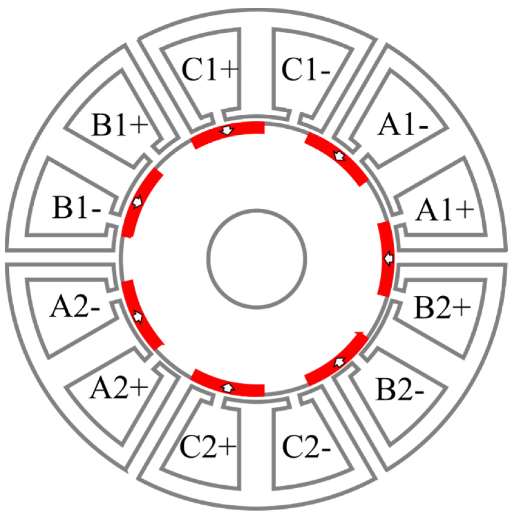
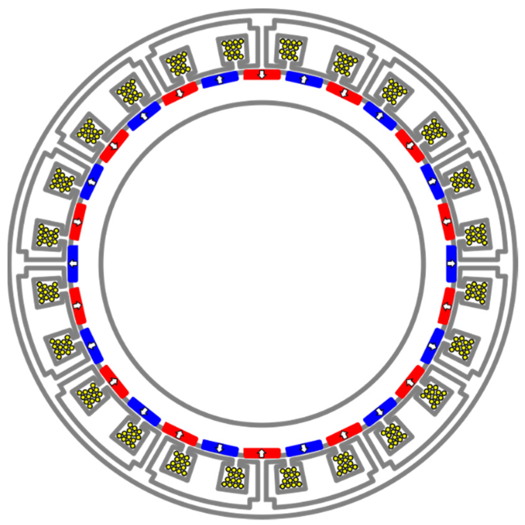
  • Designing the machine to reduce the coil cross-section size. Shorter distances from the middle to the side of the coil allow easier heat flow through thermal conduction. Possible options include using multiphase and multipole configurations, which distribute the windings in more slots;
  • Increasing the slot filling factor. This reduces the pockets of air or varnish between the wires. The winding’s composite thermal conductivity increases with the slot filling factor [79]. This can be achieved, for example, by using rectangular cross section wires;
  • Varnishing the windings. The varnish’s thermal conductivity is about an order of magnitude larger than the air’s, and it displaces the air pockets. Better results can be achieved by using vacuum impregnation as well as varnish with higher thermal conductivity.
In Figure 8 [80,81], solutions are proposed to reduce the hotspot in the middle of the coil cross-section by either extending the back iron or using a T-section heat pipe made of copper. Both solutions reach into the middle of the windings and provide a high thermal conductivity path to remove heat and thus drop the hotpot value. The hotspot reduction can be significant (26.7% in [80] and 40% [81]), although extra work needs to be carried out in order to reduce the eddy losses in the newly added extensions. Moreover, this solution comes at the expense of reducing the slot area and also raising concerns with the winding process, especially for distributed types.
The end-windings are exposed to air flow created by the rotor, although the cooling effect is reduced due to low speed, specifically for direct-drive machines. An alternative would be potting the end-windings in a high thermal conductive resin. This is not feasible however for large generators due to weight constraints. It is also possible to expose the coil slots to air flow (or another coolant) by adopting the ironless configuration in which the stator is removed [82,83], as shown in Figure 9. This also removes the heat source due to stator losses. The significant weight reduction can also lead to cost savings in the support structures, such as in the tower.
Finally, the process of natural convection on the generator’s external surface helps, and this can be improved by adding fins [79] or, for larger machines, adopting the outer rotor configuration case in which the external surface convection phenomena can be enhanced [84]. In a wind turbine, the generator is part of a nacelle (along with power electronics). Between the generator outer surface and the nacelle, there is a narrow space that acts as thermal barrier between the generator and the outside world, thus reducing somewhat the heat transfer from the outer surface and surrounding environment. The heat transfer function is also hampered by the fact that the surrounding air around the hot surfaces will also heat up. As a result, the heat transfer slows down with time for passive cooling methods as the temperature gradient between hot surfaces and surrounding air reduces. The next step is to remove the hot air around the hot surfaces by bringing in cold air to ensure that the temperature gradient remains high. This is achieved with forced air-cooling methods, as explained in the next section.

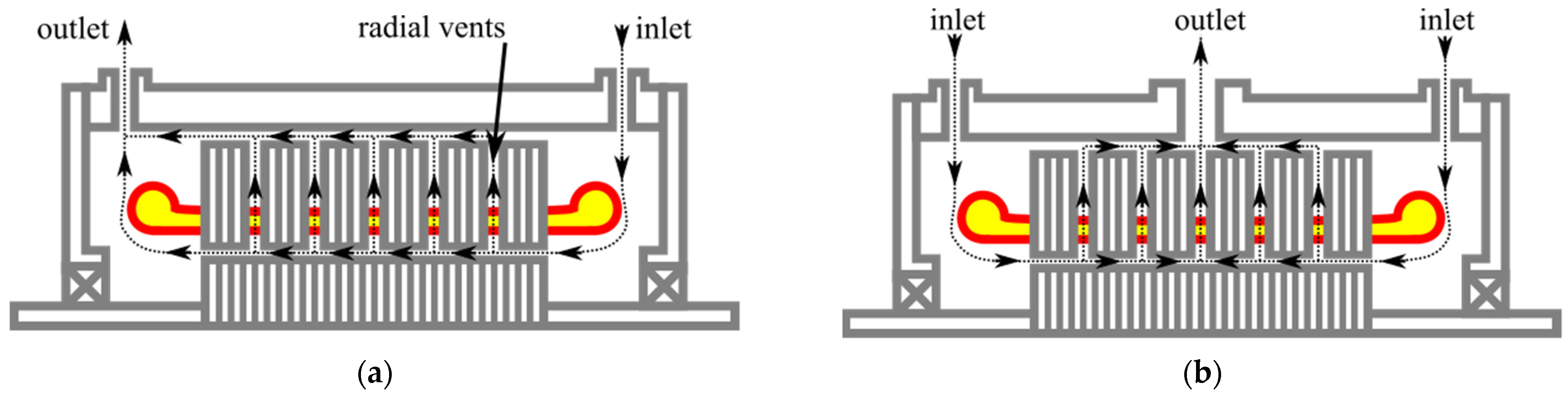
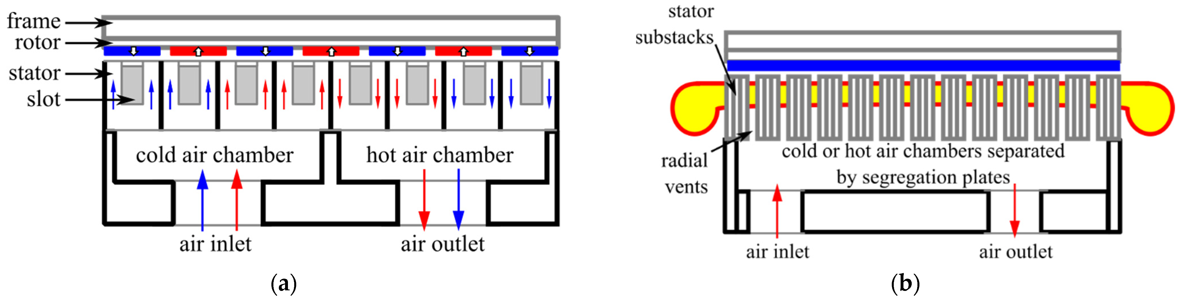
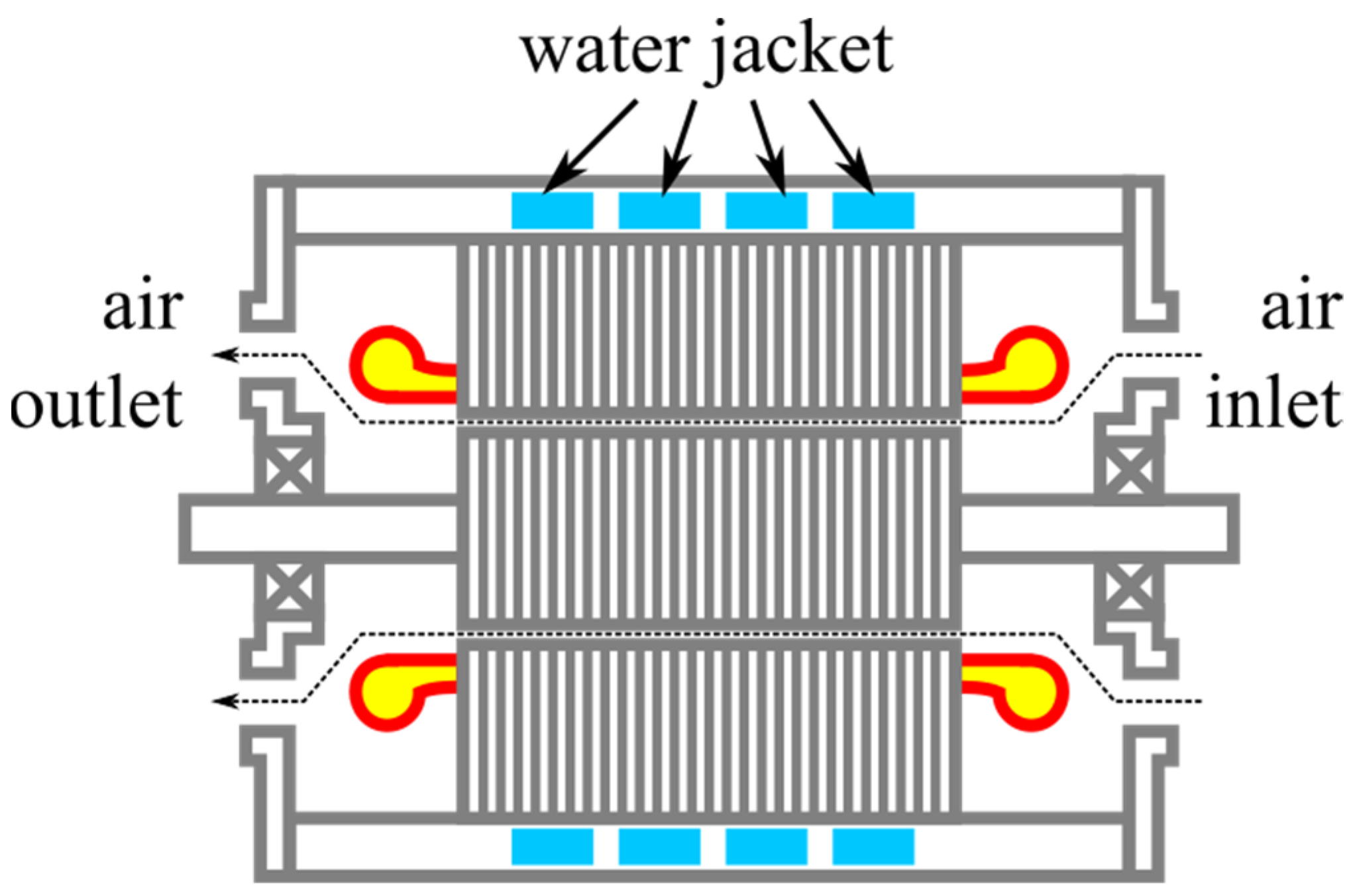
3.2. Forced Air-Cooling Systems

The forced air-cooling method can significantly improve performance compared with the passive methods at the expense of energy spent in auxiliary cooling hardware (usually a fan). A fan is used to pump air either internally through the machine or externally over the housing surface. Depending on the separation of internal from external environment, two types of housing configurations are possible:
  • Open-type housing (open cooling loop) in which the outside air is pushed through the machine. This solution is simpler but requires rugged generator internals in order to withstand contaminants;
  • Enclosed-type housing (closed cooling loop). A closed cooling circuit is used which allows purified air. An external heat exchanger is needed to re-cool the air.
Both solutions use an external fan to drive the air through the generator whose speed can be increased independently from the generator’s speed. Because the direct drive concept works at low speeds, simpler solutions that mount the fan internally and axially on the rotor shaft are excluded [85,86].
A possible configuration for forced-air cooling systems is positioning the air inlets and outlets in the end-windings regions and directing the airflow into the airgap across the machine’s length, as shown in Figure 10a. Such a configuration is called asymmetric or uni-directional [87] and can be enhanced by radial vents on the stator, which increase the available cooling surface. The radial vents can be easily implemented due to the laminar structure of the stator simply by removing laminations. This configuration has the advantage that the coolant reaches both rotor (PMs) and windings (including the end-windings), thus removing the heat. The only issue is that, due to the uni-directional flow, one end of the machine will run hotter than the other. This can be tackled with a bi-directional design, as shown in Figure 10b, in which the end-winding regions contain only the air inlets while the air outlets are connected in the middle of machine’s housing. A bi-directional or symmetrical configuration will lead to uniform cooling across the machine length.
A variation of the radial vents’ configuration is investigated in [88]. The air inlets and outlets are positioned in alternate axial stator segments, as shown in Figure 11. Compared to the solution presented in Figure 10, the air flow path in the airgap is different. The forced air travels circumferentially from a stator axial segment to the next one. This variation is simpler and reduces the ventilation losses and number of inlets and outlets. However, it comes at the expense of a non-uniform heating as the axial segment containing the hot air chamber will operate at a slightly higher temperature than the cold one. A similar method is described in [89] for a 3.35 MW direct-drive generator with a slightly different inlet, outlet and flow path configuration. The issue with the radial cooling channels is that they reduce the equivalent electrical length of the machine. In [90,91], the radial cooling vents’ presence in the laminations leads to a reduced performance compared to what the sum of sub-stacks might predict, and the performance is even smaller if radial cooling vents are adopted on both stator and rotor. A suggested workaround is to extend the rotor over the stack length in order to compensate for the performance drop.
In Figure 12 [92], flux gaps are used as axial vents with the air inlets and outlets located on the machine housing in the end-caps. This solution takes advantage of the existing flux-gaps and, compared with the radial vents configuration, no modification to the stator is required. As with the radial vents configuration, it requires external cooling hardware to pump air through the machine.
The forced air-cooling methods are safe and easy to maintain. The forced air-cooling method is also easy to implement and reaches all the important surfaces to be cooled in the generator. The method can provide sufficient cooling and can be enhanced by optimizing the airflow through the machine or by improving passive cooling as well. However, due to its inefficiency, forced-air cooling hardware is often bulky and noisy as well as energy intensive. The inefficiency can be traced to the coolant (air) properties of thermal conductivity and specific heat, both of which have low values, with the outcome that the convection process removes little heat. In [14], it is shown that after a certain rated power value, the forced-air cooling method is no longer economically feasible. With the current trend of developing larger generators, it is foreseeable that at some point in the future, cooling systems based on forced air will become economically and technologically unfeasible. A solution could be using liquid cooling methods, and these are described next.

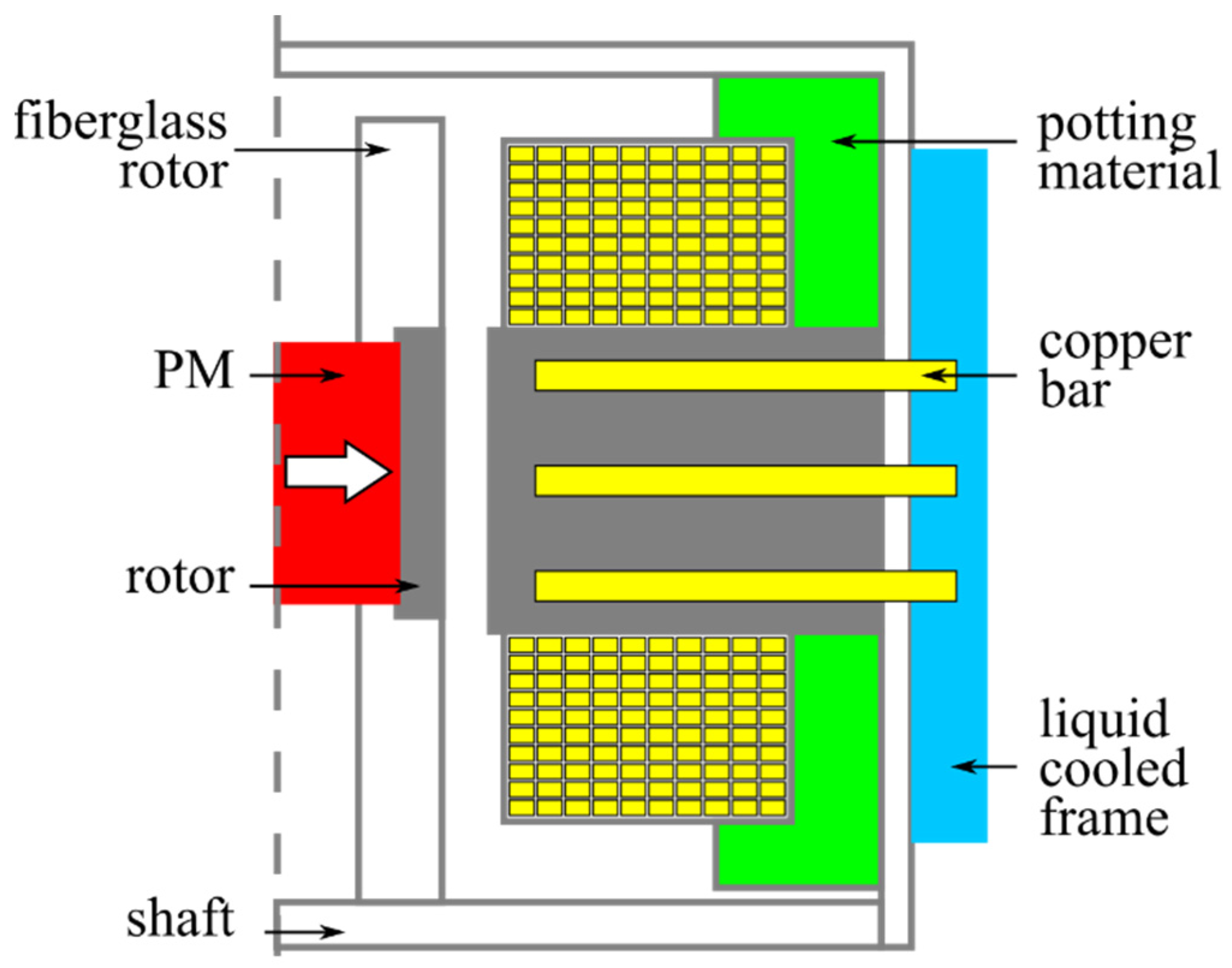
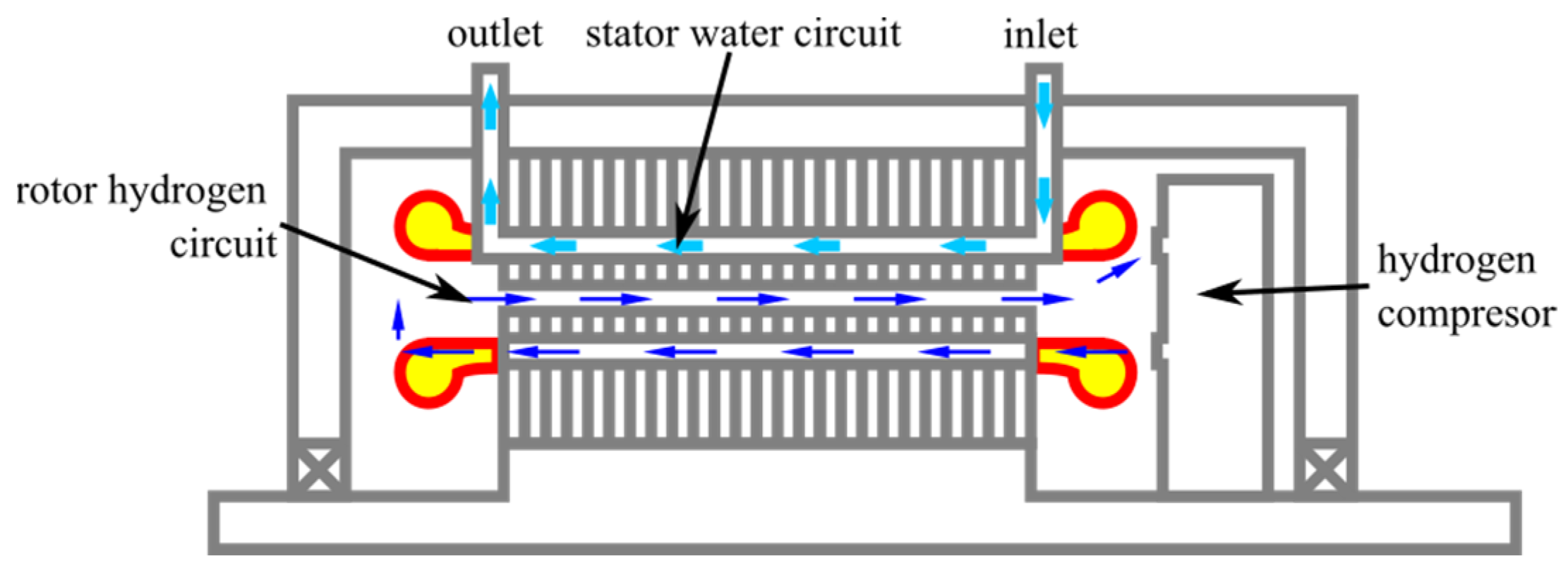
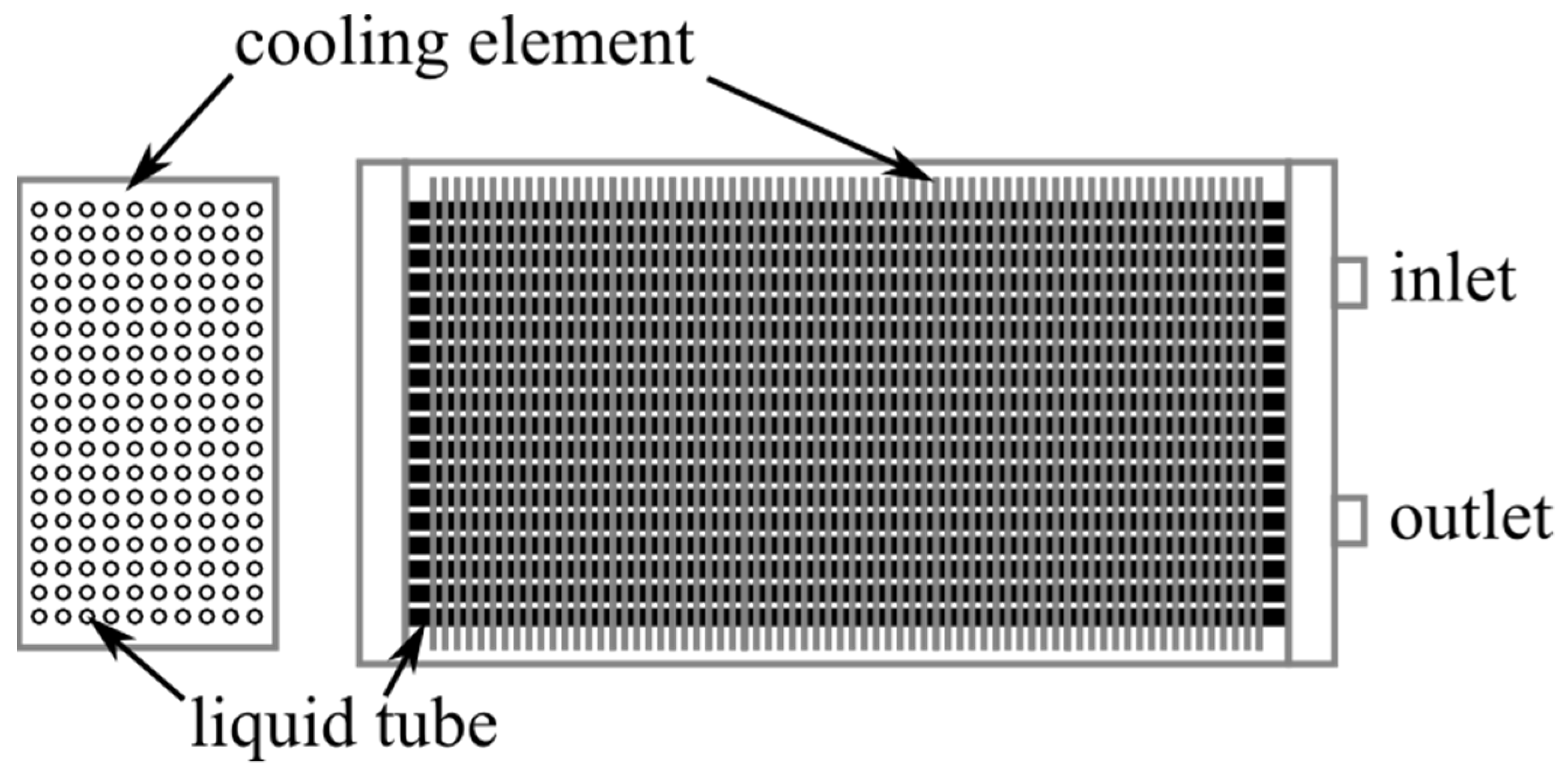
3.3. Liquid Cooling Methods

The liquid-based cooling methods offer a more compact solution compared with the forced-air ones. Some of the typical coolants used in liquid cooling are given in Table 3. The most basic is water, which performs well but has the drawbacks of a relatively high freezing point (the 0 °C value is commonly attainable during winter in regions where offshore wind turbines are installed) and high electric conductivity, which can affect the generator through corrosion and short-circuits if leaks occur. A mixture of water–glycol (in various concentrations) can tackle the freezing point issue, albeit with reduced performance. Potential oil leaks are less severe than water as the oil has electrical insulating properties and will not short-circuit anything in case of leaking. Hydrogen and helium are used for heavy cooling applications by being reduced first to a liquid state with a very low temperature and then circulated as a coolant through the generator. Examples include superconducting generators where the windings need to operate at a very low temperature to achieve the superconductor effect and large generators with very large losses where other liquid methods would not suffice.
A typical formula that can be used to approximate the cooling system performance based on the coolant fluid properties is given for example in [94]:
Q min = P loss ρ coolant c p coolant Δ T
where Qmin is the minimum amount of coolant flow rate needed to remove a total of ∑Ploss losses, ΔT = Toutlet − Tinlet is the temperature rise of the coolant between the inlet and the outlet, and ρcoolant and cpcoolant are the density and specific heat of the coolant. Equation (5) is based on the conservation of energy, and the inclusion of ρcoolant allows obtaining Qmin in m3/s and further in L/min units. In order to fairly compare various coolant fluids (for example, from Table 3), ∑Ploss and ΔT should be kept at the same value for each fluid, with lower values of Qmin denoting better cooling capabilities (i.e., less fluid volume is needed for cooling). With these, the outcome of Equation (5) depends only on the coolant density and shows that the best performing liquid in Table 3 is water followed by water/glycol and finally oil. Using the same reasoning, it can be shown that the liquids from Table 3 perform better than air, due to their higher density and specific heat.
Compared to air, the liquid-based methods are localized to a part of the generator as the cooling liquid must be contained and circulated between the inside of the generator and the outside heat exchanger and pump. Depending on the location, the cooling liquid method can be implemented as a water jacket, slot jacket, hollow conductor or hollow shaft, or the stator can be sealed from the rotor and flooded (usually with oil).
The jacket for a radial field machine is a hollow cylindrical structure containing the liquid pipes connected in various configurations together with the liquid inlets and outlets [29,95,96]. For axial field machines, a disk-like jacket is employed [30,97]. It is attached to the stator, acting as a housing as well for small and medium power generators with inner rotor configurations. Representative examples of jackets using a 50/50 mixture of water and glycol are given in [95] and shown in Figure 13. Water jackets in particular can be used in systems up to the lower range of MW rated power and are covered by the IC71W cooling standard.
The liquid jackets are a non-intrusive way of cooling a generator, being located away from problematic regions where they could displace active materials or introduce parasitic effects such as eddy currents induced in metal liquid pipes. They are also the most maintainable of the liquid methods, as the cooling pipes are located in an accessible area and can be inspected or replaced due to fouling. The liquid cooling jacket is relatively far away from the end-windings, with the consequence that the windings hotspot will move from the slot into the end-windings. Most importantly, the liquid jackets are positioned much further away from the PMs across the airgap and can fail to keep the PMs’ temperature below the demagnetization value. The direct-drive machines for wind power application stand out due to their low speed, which in turn ensures lower heat transfer between the rotor and the stator (due to laminar or low turbulence airflow in the airgap [31,79]). Due to the application type, it is not possible to increase the rotor speed. Slightly modified versions of liquid jacket methods protrude into the generator until the airgap. In Figure 14 [93], for example, a water jacket that extends into the existing flux barriers is described. The method is similar to the forced-air method, using also flux barriers, as described in the previous section. However, a significant difference is that extra walls are needed to contain the water and prevent a short-circuit. An approach using transmission oil that can freely circulate from the flux barriers through the airgap and rotor is also studied. The authors of [93] conclude that the oil method is suitable only for small machines due to high pressure drop and friction due to oil viscosity.
Another solution, more intrusive than jackets, is the water cold plates [98,99], which protrude into the stator up to the airgap edge and displace some of the stator laminations. The water cold plates are hollow and circulated with water and can be seen as the water equivalent of the forced-air radial vents described in the previous section. Fasquelle and Laloy in [98], for example, describe the concept as applied to a 3 MW PM synchronous generator. Fan et al. in [99] describe a similar method and go further by adding cold plates at the stator ends in the proximity of the end-windings, as shown in Figure 15. Thus, the issues of not reaching the end-windings and PMs are somewhat resolved at the expense of losses through eddy currents induced in the metal walls of the cold plates.
The copper conductors that make the windings can be manufactured hollow, and the interior can be used to circulate a cooling fluid, Figure 16. In [100,101], for example, hollow conductors are used for windings in an outer rotor direct-drive PM generator. In [102], the concept is scaled up for a 777 MVA hydro-generator. Various liquid coolants are explored in [100]. The hollow copper conductors have stainless steel tubes inserted for mechanical support.
The hollow conductor approach solves the issue of the cooling of end-windings. It also scales up well since larger machines have a greater slot area. However, it does not fully tackle the PM issues, although the method should perform better than the liquid jacket since it is closer to the PMs. Moreover, it is suitable only for larger machines where slot space is sufficient to accommodate hollow conductors. The skin effect can also be present. The coil length is also an issue as longer coils will overheat the coolant and suffer from pressure drops. Finally, this method is suitable for simple coil shapes such as the concentrated types. For distributed windings, this solution is difficult to implement except for a select number of winding types. In particular, coils with longer end-windings and complicated shapes are difficult to achieve as the inner hollow conductor has to be accommodated, resulting in a higher pressure drop.
A related method to hollow conductors is the slot water jacket cooling systems in which pipes are inserted through the slot and are parallel with the conductors, Figure 17 [103]. Just like for the hollow conductor method, the cooling system is in the proximity of the windings, which are the main source of heating in the generator, although they do not deal as effectively with the end-windings. Concerning the PMs, especially the configuration with the water pipe placed near the airgap could stand out in terms of performance. Moreover, the pipe is larger in diameter and shorter in length compared with a hollow conductor, which can lead to lower pressure drops. On the downside, the water pipes also compete with the conductors for valuable slot space. The pipe metal walls also collect eddy currents, which decrease performance and efficiency. A workaround the metal pipe walls was proposed in [104] by Schiefer and Doppelbauer. The water slot channel is formed by using a mold during the casting process of the resin inside the slot winding. The conductors have a rectangular section and are positioned to form two inner empty regions inside the slot which will accommodate the water channels. A polyimide thin insulation layer bonds to the resin and forms the water channels walls. One of the two water channels is placed close to the slot opening to displace conductors from a region that incurs AC losses.
The hollow-shaft method [105,106,107] is used for high-speed applications such as turbogenerators in close proximity to the windings, Figure 18. Wang et al. [107] investigate a method in which oil is pumped in the rotor shaft. Rotary couplings ensure the connection between the rotating shaft and stationary oil pump. Although this method is not the most relevant to direct-drive generators, for wind power, it has potential to be used in a hybrid configuration with another cooling method that focuses on the stator. In addition, it may not be suitable for an outer rotor direct drive configuration.
The flooded cooling method [108,109] implies sealing the rotor from the stator and flooding the stator with oil. Compared with the previous liquid cooling methods, the flooded method performs better as it reaches all the surfaces on the stator. The oil is the only suitable liquid for this application as it has a high electric resistivity and it does not corrode or short-circuit anything. The stator laminations can have channels (or, as in [109], Figure 19, axial flux gaps) which can enhance the cooling performance. Although a bit more performant than the hollow-shaft method, it is still limited as the coolant does not reach the PMs on the rotor. Therefore, it is more suitable for high-speed applications where the heat transfer between the rotor and stator is higher due to increased turbulence. Another downside of this method is that it adds significant weight to the machine as the stator needs to be filled with oil.
The liquid-based methods perform better compared with the forced-air methods. However, the multi-phase cooling methods can outperform the liquid-based ones, and they are presented next.

3.4. Multi-Phase Cooling Methods

The multi-phase methods can be even more performant and compact than the methods described in the previous sections. The multi-phase aspect refers to coolant fluid being composed of two states (or phases) of liquid and gas. Two methods of achieving this are possible, mainly through spraying and evaporation, and are described next.
When spraying liquid coolant through high pressure nozzles, the resulting cooling fluid touching the hot surfaces will be an air/liquid mist. In Figure 20, oil is used in order to reach the end-windings in a direct cooling-type method. The nozzles’ position and orientation are very important and localize the cooling to the surface of interest. Due to this, the amount of coolant can be much more reduced. However, the spray cover of the hot surface may be limited due to the spray droplets not reaching all the surfaces.
The second multi-phase method involves the evaporation of water due to it coming in contact with a very hot surface. The coolant is partially or totally transformed from one phase (liquid) to another one (vapors). In Figure 21, the principle is illustrated for water and hollow winding conductors [111]. The water is injected into a chamber called a condenser and then down a tube until it reaches the hollow stator conductors. Due to high heat, it changes phase into vapors that ascend into the condenser, removing heat from the windings. In the condenser, the water drops back to liquid, and the cycle begins again. In [111], the principle is applied to a 2 MW direct-drive wind turbine. The condenser is a simple external chamber cooled through natural convection. Both the generator and power electronics are cooled using this system. It is also scalable to a much higher rated power, being applied in the past to hydro-generators.
Most of the single and double phase-based methods represented so far have short-comings and may not be enough by themselves for direct-drive generators in wind power application. However, they can be combined with a secondary cooling method, and this is explored in the next section.

3.5. Hybrid Cooling Methods

Hybrid methods use two combined methods to cool the generator—for example, gas–liquid or liquid–liquid. This implies two separate cooling systems working on separate parts of the generator and complementing each other. Thus, they directly address the localization issues of the liquid and multiphase cooling methods. The main use for the hybrid methods is in scenarios in which the rotating and stationary parts of the generator cannot be sufficiently cooled by one method alone or the cost is prohibitively high for a single method.
A first example is given in Figure 22, where a liquid jacket is combined with passive cooling elements for an axial PM machine. Potting material and copper bars extend from the water jacket into the machine extracting heat and thus overcoming some of the short-comings of the jacket-only method. This system retains the low maintenance requirements of the jacket-only method.
In Figure 23 [112], a hybrid cooling system employing both forced air and water is investigated. Compared with the previous method, the maintenance requirements are increased as two active cooling systems are present. A similar system is employed in [113] for a four-quadrant transducer (a type of magnetically geared machine) that regulates the torque and speed transmission to wheels from an internal combustion system. It has a dual rotor system, which is cooled using forced air throughout, and a stator, which is water cooled. The rotor has a complicated mechanical structure that involves hard to reach areas for cooling, and thus there is a need to use the second forced-air method of cooling.
In Figure 24 [114], a 1992 MVA turbogenerator cooling system is presented. The stator is cooled using water pumped through hollow conductors, where it is necessary to remove around 20 MW heat sources. The rotor is cooled using hydrogen gas.
Due to specific requirements, a second cooling method may be necessary. This however incurs additional maintenance and also raises issues of reliability since there are more parts that are prone to failure. Smaller machines may not allow the implementation of a hybrid cooling method due to size constraints. The next section discusses the maintenance and reliability issues as well as any effect they may have on performance.

3.6. R&D Cost, Maintenance, Performance and Reliability

In the previous sections, the various cooling methods have been introduced gradually, in order of their complexity, performance and maintenance requirements. This order can also reflect the design process required to assess the cooling method effectiveness [79,115,116,117,118,119,120,121,122]. Simpler methods such as forced air and water cooling can be tackled with simple lumped thermal and parameter circuit networks (LPTN). Computational fluid dynamics models (CFD) are significantly more complicated, use more computational resources and are used for complicated geometries.
The type of cooling system chosen has consequences for maintenance and reliability, amongst other things. In addition, redundancy is necessary, thus increasing the cooling system size. The wind power generation industry often prefers less performant conservative solutions against more performant but riskier ones. The steps that can be taken to increase reliability and reduce maintenance are as follows:
  • Adopt a safe cooling fluid inside the generator like air or an inert gas. The various sealing systems inside the generator (which prevent leaks) are simpler and require very little maintenance. In the event of a leak, the generator will not be damaged. Air has also the advantage that it is not affected by a freezing point, unlike liquids;
  • Adopt a closed loop system. The air is circulated inside the generator and through an external heat exchanger. The generator internals are not exposed to external contaminants like dust, salt, etc., which can further lead to corrosion.
An implementation of these rules is given in Figure 25. The aforementioned closed-loop system is implemented by connecting the generator with the primary cooling circuit of a heat exchanger external heat exchanger. The heat exchanger also contains a secondary cooling circuit. The heated air from the generator passes into the primary cooling circuit where the heat is removed into the secondary circuit and into the surrounding environment. Based on the coolant present in the secondary circuit, the cooling solutions can be as follows [87]:
  • Air to air (totally enclosed air-to-air cooled—TEAAC or closed air circuit, air cooled—CACA). The primary circuit coolant is air, and the secondary circuit coolant is also air;
  • Water to air (totally enclosed water to air—TEWAC or closed air circuit, water cooled—CACW). The primary circuit coolant is air, while the secondary circuit coolant is water.
For TEWAC option, it can be seen that, compared with a liquid method, for example, the liquid pipes are moved outside the generator where they can be easily accessed for maintenance.
An example of a heat exchanger using liquid pipes (for TEWAC/CACW option) is given in Figure 26. It consists of a large number of pipes circulated by water. The pipe’s outer surface is in contact with the hot air coming from the generator and acts like a heat exchanger.
To detect water leaks inside the primary cooling circuit, a double tube system can be installed in the external heat exchanger, as shown in Figure 27. Furthermore, although the TEWAC/CACW system performs better than the TEEAC/CACA one, it relies on a local water source. The secondary cooling circuit is an open loop configuration, thus exposing the heat exchanger to corrosion, mineral deposits, fouling, etc. To address this, the second cooling circuit can be closed, forming a closed loop, and a third cooling circuit can be added in an open loop configuration using external air [125]. This new configuration is called CAWA (closed air circuit, water circuit, air cooled) and in terms of performance is better than TEEAC/CACA and safer than TEWAC/CACW.
These methods are safe but limited in performance due to the low effectiveness of the air as a cooling fluid. Furthermore, using liquid-based methods, for example, can lead to a significant performance increase but is also riskier due to potential liquid leaks, which can damage the generator. Various compromises between safety and performance with liquid are also possible.

4. Conclusions

Choosing a suitable cooling method for direct-drive generators in wind power generation cannot be done based on performance alone. A compromise with the reliability and maintenance requirements is required. Therefore, the lowest performing but safest cooling methods are usually adopted in the industry, especially for large power wind turbines. The direct-drive configuration itself restricts the cooling methods that can be used on it. Table 4 provides a side-by-side comparison of the performance, maintenance requirements, weight, cooling capacity, energy consumed by the cooling hardware and noise. This summary can help to choose the cooling method suitable for any application. The following were considered when attributing value points to each method:
  • The highest performing method is the hybrid one, while the lowest performing is the passive cooling (or no cooling). Closed-loop systems incur a penalty as they add extra heat exchangers, which limit heat extraction (i.e., no heat exchanger is perfect). Flooded stator and oil spray can perform better since they are direct cooling types;
  • In terms of maintenance, the passive cooling system requires no maintenance (since no active cooling system is present) while the hybrid method needs the most maintenance as it employs two different methods. In addition, the open-loop systems also have increased maintenance since they are exposed to contaminants from the outside environment. For large and offshore generators, expensive filters are required to prevent the contaminants getting inside (the maintenance shift focus on the filter lifetime). Flooded stator and oil spray methods are regarded as higher maintenance than forced-water types (water is contained in the jacket—oil is not);
  • It is considered that the total weight of the generator and cooling system combined should be less than a design with no cooling present; otherwise, the cooling system brings no benefits. From this point of view, a generator with passive cooling has the largest weight. Adding any active cooling method will bring an overall weight reduction. Closed loop systems will be heavier than their open-loop counterparts as they need additional heat exchangers. The flooded stator method is also penalized here due to the weight of the liquid inside the stator;
  • The cooling capacity (also a measure of scalability) is the lowest for the passive cooling systems. In this case, increasing the rated power of the generator means necessarily increasing the generator size and weight. Adding an active cooling method ensures that the generator size can be kept small, up to a certain point, depending on the coolant used. The hybrid method is the best as it combines advantages from both methods. Closed loops incur a penalty in cooling capacity compared to open-loop methods of the same coolant type;
  • In terms of energy, the worst method is the forced-air closed loop method. For this case, fans are required to circulate the coolant in both the primary and secondary cooling circuits. The low effectiveness of air as a coolant fluid is reflected in larger and faster fans needed to increase both the mass flow and air velocity. This is reflected in the cooling hardware as well—a water pump, for example, will be much more compact and less energy intensive;
  • The noise is important only for forced air methods due to the large fan size usually employed. For other methods, the pumps are usually smaller and isolated from the outside environment.
The safest option currently available to designers for high power direct-drive generators is the forced air-based method, in a closed-loop configuration, with an external heat exchanger. This option, although widely adopted, is not future-proof as with the current trend increase of generated power, this method will not suffice. The most performant and flexible method is the hybrid one as it can combine two cooling systems that can complement each other. This method is usually adopted in larger generators (hundreds of MVA), which are usually onshore and easily accessible for maintenance. For wind power generation, which has an important offshore trend, the maintenance can be a drawback as two separate cooling systems need to be serviced.
Selecting a potential new cooling technology is the first step in the product development process. It takes a few years to develop and bring the new cooling solution to the market. As with any new technology (or new application of an existing technology), there are potential risks with the outcome that the development process can reach a dead end. In order to tackle the risks, a design failure mode and effect analysis (DFMEA) can be conducted during the first step. This will identify, avoid or propose solutions to potential risks down the line.
This study provides a qualitative way to select a cooling method for direct-drive generators. Future work should focus on developing a quantitative approach, which could provide even better insight into selecting a cooling method. Such approach could use flexible modeling tools such as LPTN (for generator) and flow networks (for cooling hardware). The quantitative study could cover a range of parameters of interest and also identify clear answers to comparisons between various cooling technologies.

Author Contributions

Conceptualization, P.T., R.N., Z.-Q.Z., Z.A.; methodology and validation, P.T., R.N.; formal analysis and investigation, P.T., R.N.; resources, Z.-Q.Z., Z.A.; writing—original draft preparation, P.T., R.N.; writing—review and editing, Z.-Q.Z., Z.A.; supervision, Z.-Q.Z.; project administration, Z.-Q.Z., Z.A.; funding acquisition, Z.-Q.Z., Z.A. All authors have read and agreed to the published version of the manuscript.

Funding

This research work is supported by UK EPSRC Prosperity Partnership “A New Partnership in Offshore Wind” under Grant No. EP/R004900/1.

Data Availability Statement

Not applicable.

Conflicts of Interest

The authors declare no conflict of interest. The funders had no role in the design of the study; in the collection, analyses, or interpretation of data; in the writing of the manuscript; or in the decision to publish the results.

References

  1. United Nations. Adoptions of the Paris Agreement; United Nations: Paris, France, 2015. [Google Scholar]
  2. Lee, J.; Zhao, F. Global Wind Report 2021; Global Wind Energy Council: Brussels, Belgium, 2021. [Google Scholar]
  3. Vestas Wind Systems. Turbines, Life Cycle Assesssment of Offshore and Onshore Sited Wind Power Plants Based on Vestas V90-3.0MW; Vestas Wind Systems: Randers, Denmark, 2006. [Google Scholar]
  4. Haapala, K.R.; Prempreeda, P. Comparative life cycle assessment of 2.0 MW wind turbines. Int. J. Sustain. Manuf. 2014, 3, 170–185. [Google Scholar] [CrossRef]
  5. Energy Payback of a Wind Turbine, Vestas Wind Systems. Available online: https://www.vestas.com/en/sustainability/environment/energy-payback (accessed on 1 December 2021).
  6. Sajid, M.; Hassan, I.; Rahman, M. An overview of cooling of thermoelectric devices. Renew. Sustain. Energy Rev. 2017, 78, 15–22. [Google Scholar] [CrossRef]
  7. Siemens Gamesa and Siemens Energy to Unlock a New Era of Offshore Green Hydrogen Production, 13 January 2021. Available online: https://press.siemens-energy.com/global/en/pressrelease/siemens-gamesa-and-siemens-energy-unlock-new-era-offshore-green-hydrogen-production (accessed on 1 December 2021).
  8. Ani, S.O.; Polinder, H.; Ferreira, J.A. Comparison of Energy Yield of Small Wind Turbines in Low Wind Speed Areas. IEEE Trans. Sustain. Energy 2012, 4, 42–49. [Google Scholar] [CrossRef]
  9. Morandin, M.; Fornasiero, E.; Bolognani, S.; Bianchi, N. Torque and Power Rating of a Wind-Power PM Generator Drive for Maximum Profit-to-Cost Ratio. IEEE Trans. Ind. Appl. 2013, 49, 866–872. [Google Scholar] [CrossRef]
  10. Polinder, H.; van der Pijl, F.F.A.; de Vilder, G.J.; Tavner, P.J. Comparison of direct-drive and geared generator concepts for wind turbines. IEEE Trans. Energy Convers. 2006, 21, 725–733. [Google Scholar] [CrossRef]
  11. Camm, E.; Behnke, M.R.; Bolado, O.; Bollen, M.; Bradt, M.; Brooks, C.; Dilling, W.; Edds, M.; Hejdak, W.J.; Houseman, D.; et al. Characteristics of wind turbine generators for wind power plants. In Proceedings of the 2009 IEEE Power & Energy Society General Meeting, Calgary, AB, Canada, 26–30 July 2009; pp. 1–5. [Google Scholar] [CrossRef]
  12. Jiang, R.; Wang, J.; Guan, Y. Overview of Multi-MW Wind Turbines and Wind Parks. IEEE Trans. Ind. Electron. 2011, 58, 1081–1095. [Google Scholar] [CrossRef]
  13. Bang, D.; Polinder, H.; Shrestha, G.; Ferreira, J.A. Promising direct-drive generator system for large wind turbines. In Proceedings of the 2008 Wind Power to the Grid—EPE Wind Energy Chapter 1st Seminar, Delft, The Netherlands, 27–28 March 2008. [Google Scholar]
  14. Semken, R.S.; Polikarpova, M.; Röyttä, P.; Alexandrova, J.; Pyrhönen, J.; Nerg, J.; Mikkola, A.; Backman, J. Direct-drive permanent magnet generators for high-power wind turbines: Benefits and limiting factors. IET Renew. Power Gener. 2012, 6, 1–8. [Google Scholar] [CrossRef]
  15. Polinder, H.; Ferreira, J.A.; Jensen, B.B.; Abrahamsen, A.B.; Atallah, K.; McMahon, R.A. Trends in Wind Turbine Generator Systems. IEEE J. Emerg. Sel. Top. Power Electron. 2013, 1, 174–185. [Google Scholar] [CrossRef]
  16. Bang, D.; Polinder, H.; Shrestha, G.; Ferreira, J.A. Review of generator systems for direct-drive wind turbines. In Proceedings of the EWEC 2008, Brussels, Belgium, 31 March–3 April 2008. [Google Scholar]
  17. Siemens Gamesa Wind Turbines and Services. Available online: https://www.siemensgamesa.com/en-int/products-and-services (accessed on 4 February 2022).
  18. V236-15.0 MW at a Glance, Vestas. Available online: https://www.vestas.com/en/products/offshore/V236-15MW (accessed on 1 December 2021).
  19. GE Renewable Energy Products Page. Available online: https://www.ge.com/renewableenergy/wind-energy (accessed on 4 February 2022).
  20. The Nordex Group Portfolio. Available online: https://www.nordex-online.com/en/product/product-main-page/ (accessed on 4 February 2022).
  21. Enercon, E-160 EP5. Available online: https://www.enercon.de/en/products/ep-5/e-160-ep5/ (accessed on 12 January 2022).
  22. Mueller, M.; Polinder, H. Electrical Drives for Direct Drive Renewable Energy Systems; Woodhead Publishing Ltd.: Cambridge, UK, 2013. [Google Scholar] [CrossRef]
  23. SG 8.0-167 DD Offshore Wind Turbine, Siemens-Gamesa. Available online: https://www.siemensgamesa.com/en-int/products-and-services/offshore/wind-turbine-sg-8-0-167-dd (accessed on 1 December 2021).
  24. Haliade-X Offshore Wind Turbine, GE Renewable Energy. Available online: https://www.ge.com/renewableenergy/wind-energy/offshore-wind/haliade-x-offshore-turbine (accessed on 1 December 2021).
  25. SG 11.0-200 DD Offshore Wind Turbine, Siemens-Gamesa. Available online: https://www.siemensgamesa.com/en-int/products-and-services/offshore/wind-turbine-sg-11-0-200-dd (accessed on 1 December 2021).
  26. SG 14-222 DD Offshore Wind Turbine, Siemens-Gamesa. Available online: https://www.siemensgamesa.com/en-int/products-and-services/offshore/wind-turbine-sg-14-222-dd (accessed on 1 December 2021).
  27. Popescu, M.; Staton, D.A.; Boglietti, A.; Cavagnino, A.; Hawkins, D.; Goss, J. Modern heat extraction systems for power traction systems. IEEE Trans. Ind. Appl. 2016, 52, 2167–2175. [Google Scholar] [CrossRef]
  28. Nishanth, F.; Johnson, M.; Severson, E.L. A Review of Thermal Analysis and Management of Power Dense Electric Machines. In Proceedings of the 2021 IEEE International Electric Machines & Drives Conference (IEMDC), Hartford, CT, USA, 17–20 May 2021; pp. 1–8. [Google Scholar] [CrossRef]
  29. Gai, Y.H.; Kimiabeigi, M.; Yew, C.C.; Deng, X.; Popescu, M.; Goss, J.; Staton, D.A.; Steven, A. Cooling of automotive traction motors: Schemes, examples, and computation methods. IEEE Trans. Ind. Electron. 2019, 68, 1681–1692. [Google Scholar] [CrossRef]
  30. Polikarpova, M.; Ponomarev, P.; Lindh, P.; Petrov, I.; Jara, W.; Naumanen, V.; Tapia, J.A.; Pyrhonen, J. Hybrid Cooling Method of Axial-Flux Permanent-Magnet Machines for Vehicle Applications. IEEE Trans. Ind. Electron. 2015, 62, 7382–7390. [Google Scholar] [CrossRef]
  31. Boglietti, A.; Cavagnino, A.; Staton, D.; Shanel, M.; Mueller, M.; Mejuto, C. Evolution and Modern Approaches for Thermal Analysis of Electrical Machines. IEEE Trans. Ind. Electron. 2009, 56, 871–882. [Google Scholar] [CrossRef]
  32. Growald, P.O.; Kern, T.A. Traction motor cooling systems: A literature review and comparative study. IEEE Trans. Transp. Electrif. 2021, 7, 2892–2913. [Google Scholar] [CrossRef]
  33. Miller, T.J.E. Brushless Permanent-Magnet and Reluctance Motor Drives; Clarendon Press: Oxford, UK, 1989. [Google Scholar]
  34. Chen, J.Y.; Nayar, C.V.; Xu, L.Y. Design and finite-element analysis of an outer-rotor permanent-magnet generator for directly coupled wind turbines. IEEE Trans. Ind. Electron. 2000, 36, 3802–3809. [Google Scholar] [CrossRef]
  35. Choi, J.-Y.; Jang, S.-M.; Song, B.-M. Design of a direct-coupled radial-flux permanent magnet generator for wind turbines. In Proceedings of the 2021 IEEE International Electric Machines & Drives Conference (IEMDC), Hartford, CT, USA, 17–20 May 2021; pp. 1–6. [Google Scholar] [CrossRef]
  36. Pyrhonen, J.; Alexandrova, Y.; Semken, R.S.; Hamalainen, H. Wind power electrical drives for permanent magnet generators—Development in Finland. In Proceedings of the Elektro 2012, Rajecke Teplice, Slovakia, 21–22 May 2012. [Google Scholar]
  37. Kowal, D.; Sergeant, P.; Dupre, L.; Vandenbossche, L. The effect of the electrical steel properties on the temperature distribution in direct-drive PM synchronous generators for 5 MW wind turbines. IEEE Trans. Magn. 2013, 49, 5371–5377. [Google Scholar] [CrossRef]
  38. Xue, S.; Feng, J.H.; Guo, S.Y.; Peng, J.; Chu, W.Q.; Zhu, Z.Q. A new iron loss model for temperature dependencies of hysteresis and eddy current losses in electrical machines. IEEE Trans. Magn. 2018, 54, 8100310. [Google Scholar] [CrossRef]
  39. Xue, S.; Zhu, Z.Q.; Wang, Y.; Feng, J.G.; Guo, S.Y.; Li, Y.F.; Chen, Z.C.; Peng, J. Thermal-loss coupling analysis of an electrical machine using the improved temperature-dependent iron loss model. IEEE Trans. Magn. 2018, 54, 8105005. [Google Scholar] [CrossRef]
  40. Ruoho, S.; Kolehmainen, J.; Ikaheimo, J.; Arkkio, A. Interdependence of Demagnetization, Loading, and Temperature Rise in a Permanent-Magnet Synchronous Motor. IEEE Trans. Magn. 2009, 46, 949–953. [Google Scholar] [CrossRef]
  41. Sebastian, T. Temperature effects on torque production and efficiency of PM motors using NdFeB magnets. IEEE Trans. Ind. Appl. 2002, 31, 353–357. [Google Scholar] [CrossRef]
  42. Chen, J.Q.; Chen, Z.H.; Wang, D.; Wu, L.T.; Zheng, X.Q.; Birnkammer, F.; Gerling, D. Influence of temperature on mag-netic properties of silicon steel lamination. AIP Adv. 2017, 7, 056113. [Google Scholar]
  43. Wallscheid, O. Thermal Monitoring of Electric Motors: State-of-the-Art Review and Future Challenges. IEEE Open J. Ind. Appl. 2021, 2, 204–223. [Google Scholar] [CrossRef]
  44. Ruoho, S.; Dlala, E.; Arkkio, A. Comparison of Demagnetization Models for Finite-Element Analysis of Permanent-Magnet Synchronous Machines. IEEE Trans. Magn. 2007, 43, 3964–3968. [Google Scholar] [CrossRef]
  45. ARNOLD Magnetic Technologies. RECOMA SmCo Grades. Available online: https://www.arnoldmagnetics.com/wp-content/uploads/2017/10/Recoma-Combined-160301.pdf (accessed on 12 January 2022).
  46. Pyrhonen, J.; Nerg, J.; Kurronen, P.; Puranen, J.; Haavisto, M. Permanent magnet technology in wind power generators. In Proceedings of the XIX International Conference on Electrical Machines—ICEM 2010, Rome, Italy, 6–8 September 2010; pp. 1–6. [Google Scholar] [CrossRef]
  47. McDonald, A.; Bhuiyan, N.A. On the Optimization of Generators for Offshore Direct Drive Wind Turbines. IEEE Trans. Energy Convers. 2016, 32, 348–358. [Google Scholar] [CrossRef]
  48. Arnold Magnetic Technologies, Neodymium Iron Boron Magnet Catalog. Available online: https://www.arnoldmagnetics.com/wp-content/uploads/2019/06/Arnold-Neo-Catalog.pdf (accessed on 28 November 2021).
  49. IEC. IEC 60085:2007 Electrical Insulation—Thermal Evaluation and Designation. Available online: https://standards.iteh.ai/catalog/standards/iec/2584c3d3-f618-40cc-b0fd-0f9e66f45e84/iec-60085-2007 (accessed on 28 November 2021).
  50. Grauers, A. Design of Direct-Driven Permanent-Magnet Generators for Wind Turbines. Ph.D. Dissertation, Chalmers University of Technology, Goteborg, Sweden, 1996. [Google Scholar]
  51. Dubois, M.R.J. Optimized Permanent Magnet Generator Topologies for Direct-Drive Wind Turbines. Ph.D. Dissertation, Technical University of Delft, Delft, The Netherlands, 2004. [Google Scholar]
  52. Damiano, A.; Marongiu, I.; Monni, A.; Porru, M. Design of a 10 MW multi-phase PM synchronous generator for direct-drive wind turbines. In Proceedings of the IECON 2013—39th Annual Conference of the IEEE Industrial Electronics Society, Vienna, Austria, 10–13 November 2013; pp. 5266–5270. [Google Scholar] [CrossRef]
  53. Jia, S.; Qu, R.; Li, J.; Fan, X.; Zhang, M. Study of direct-drive permanent-magnet synchronous generators with solid rotor back iron and different windings. IEEE Trans. Ind. Appl. 2016, 52, 1369–1379. [Google Scholar]
  54. Chen, Y.; Pillay, P.; Khan, A. PM Wind Generator Topologies. IEEE Trans. Ind. Appl. 2005, 41, 1619–1626. [Google Scholar] [CrossRef]
  55. Meier, F. Permanent-Magnet Synchronous Machines with Non-Overlapping Concentrated Windings for Low-Speed Direct-Drive Applications. Ph.D. Thesis, Royal Institute of Technology School of Electrical Engineering Electrical Machines and Power Electronics, Stockholm, Sweden, 2008. [Google Scholar]
  56. Padinharu, D.K.K.; Li, G.J.; Zhu, Z.Q.; Foster, M.P.; Stone, D.A.; Griffo, A.; Clark, R.; Thomas, A. Scaling effect on electromagnetic performance of surface-mounted permanent-magnet vernier machine. IEEE Trans. Magn. 2020, 56, 8100715. [Google Scholar] [CrossRef]
  57. Zhu, Z.Q.; Chen, J.T. Advanced Flux-Switching Permanent Magnet Brushless Machines. IEEE Trans. Magn. 2010, 46, 1447–1453. [Google Scholar] [CrossRef]
  58. Cheng, M.; Hua, W.; Zhang, J.; Zhao, W. Overview of Stator-Permanent Magnet Brushless Machines. IEEE Trans. Ind. Electron. 2011, 58, 5087–5101. [Google Scholar] [CrossRef]
  59. Li, F.; Hua, W.; Tong, M.; Zhao, G.; Cheng, M. Nine-Phase Flux-Switching Permanent Magnet Brushless Machine for Low-Speed and High-Torque Applications. IEEE Trans. Magn. 2015, 51, 8700204. [Google Scholar] [CrossRef]
  60. Shao, L.Y.; Hua, W.; Soulard, J.; Zhu, Z.Q.; Wu, Z.Z.; Cheng, M. Electromagnetic performance comparison between 12-phase switched flux and surface-mounted PM machines for direct-drive wind power generation. IEEE Trans. Ind. Appl. 2020, 56, 1408–1422. [Google Scholar] [CrossRef]
  61. Cheng, M.; Wang, J.; Zhu, S.; Wang, W. Loss Calculation and Thermal Analysis for Nine-Phase Flux Switching Permanent Magnet Machine. IEEE Trans. Energy Convers. 2018, 33, 2133–2142. [Google Scholar] [CrossRef]
  62. Ojeda, J.; Simoes, M.; Li, G.-J.; Gabsi, M. Design of a Flux-Switching Electrical Generator for Wind Turbine Systems. IEEE Trans. Ind. Appl. 2012, 48, 1808–1816. [Google Scholar] [CrossRef]
  63. Muljadi, E.; Butterfield, C.; Wan, Y.-H. Axial-flux modular permanent-magnet generator with a toroidal winding for wind-turbine applications. IEEE Trans. Ind. Appl. 1999, 35, 831–836. [Google Scholar] [CrossRef]
  64. Ani, S.O.; Polinder, H.; Ferreira, J.A. Low cost axial flux permanent magnet generator for small wind turbines, In Proceedings of the ECCE2021, Raleigh, NC, USA, 15–20 September 2012.
  65. Marignetti, F.; Colli, V.D.; Coia, Y. Design of Axial Flux PM Synchronous Machines Through 3-D Coupled Electromagnetic Thermal and Fluid-Dynamical Finite-Element Analysis. IEEE Trans. Ind. Electron. 2008, 55, 3591–3601. [Google Scholar] [CrossRef]
  66. Kumar, R.; Zhu, Z.-Q.; Duke, A.; Thomas, A.; Clark, R.; Azar, Z.; Wu, Z.-Y. A Review on Transverse Flux Permanent Magnet Machines for Wind Power Applications. IEEE Access 2020, 8, 216543–216565. [Google Scholar] [CrossRef]
  67. Husain, T.; Hasan, I.; Sozer, Y.; Husain, I.; Muljadi, E. A comprehensive review of permanent magnet transverse flux ma-chines: Use in direct-drive applications. IEEE Ind. Appl. Mag. 2020, 26, 87–98. [Google Scholar] [CrossRef]
  68. Ishizaki, A.; Tanaka, T.; Takasaki, K.; Nishikata, S. Theory and optimum design of PM Vernier motor. In Proceedings of the 7th ICEMD, Durham, UK, 11–13 September 1995. [Google Scholar]
  69. Li, J.; Chau, K.T.; Jiang, J.Z.; Liu, C.; Li, W. A New Efficient Permanent-Magnet Vernier Machine for Wind Power Generation. IEEE Trans. Magn. 2010, 46, 1475–1478. [Google Scholar] [CrossRef]
  70. Li, D.; Qu, R.; Li, J. Topologies and analysis of flux-modulation machines. In Proceedings of the 2015 IEEE Energy Conversion Congress and Exposition (ECCE), Montreal, QC, Canada, 20–24 September 2015; pp. 2153–2160. [Google Scholar] [CrossRef]
  71. Padinharu, D.K.; Li, G.J.; Zhu, Z.Q.; Azar, Z.; Clark, R.; Thomas, A. Effect of airgap length on electromagnetic performance of permanent magnet Vernier machines with different power ratings. IEEE Trans. Ind. Appl. 2022, 58, 1920–1930. [Google Scholar] [CrossRef]
  72. Ani, S.; Polinder, H.; Ferreira, J. Energy yield of two generator systems for small wind turbine application. In Proceedings of the 2011 IEEE International Electric Machines & Drives Conference (IEMDC), Niagara Falls, ON, Canada, 15–18 May 2011; pp. 735–740. [Google Scholar] [CrossRef]
  73. Qu, R.; Lipo, T. Design and Parameter Effect Analysis of Dual-Rotor, Radial-Flux, Toroidally Wound, Permanent-Magnet Machines. IEEE Trans. Ind. Appl. 2004, 40, 771–779. [Google Scholar] [CrossRef]
  74. Kumar, B.R.; Kumar, K.S. Siva Design of a new dual rotor radial flux BLDC motor with Halbach array magnets for an electric vehicle. In Proceedings of the PEDES2016, Trivandrum, India, 14–17 December 2016. [Google Scholar]
  75. Bi, Y.; Chai, F.; Chen, L. The Study of Cooling Enhancement in Axial Flux Permanent Magnet Motors for Electric Vehicles. IEEE Trans. Ind. Appl. 2021, 57, 4831–4839. [Google Scholar] [CrossRef]
  76. Howey, D.A.; Childs, P.R.N.; Holmes, A.S. Air-Gap Convection in Rotating Electrical Machines. IEEE Trans. Ind. Electron. 2010, 59, 1367–1375. [Google Scholar] [CrossRef]
  77. Bergman, T.L.; Lavine, A.S.; Incropera, F.P.; Dewitt, D.P. Fundamentals of Heat and Mass Transfer, 7th ed.; John Wiley & Sons, Inc.: Hoboken, NJ, USA, 2011. [Google Scholar]
  78. Polikarpova, M. Liquid Cooling Solutions for Rotating Permanent Magnet Synchronous Machines. Ph.D. Dissertation, Lappeenranta University of Technology, Lappeenranta, Finland, 2014. [Google Scholar]
  79. Staton, D.A.; Cavagnino, A. Convection Heat Transfer and Flow Calculations Suitable for Electric Machines Thermal Models. IEEE Trans. Ind. Electron. 2008, 55, 3509–3516. [Google Scholar] [CrossRef]
  80. Zhang, F.; Gerada, D.; Xu, Z.; Zhang, X.; Tighe, C.; Zhang, H.; Gerada, C. Back-Iron Extension Thermal Benefits for Electrical Machines With Concentrated Windings. IEEE Trans. Ind. Electron. 2019, 67, 1728–1738. [Google Scholar] [CrossRef]
  81. Galea, M.; Gerada, C.; Raminosoa, T.; Wheeler, P. A Thermal Improvement Technique for the Phase Windings of Electrical Machines. IEEE Trans. Ind. Appl. 2011, 48, 79–87. [Google Scholar] [CrossRef]
  82. Zhang, Z.; Matveev, A.; Nilssen, R.; Nysveen, A. Ironless Permanent-Magnet Generators for Offshore Wind Turbines. IEEE Trans. Ind. Appl. 2013, 50, 1835–1846. [Google Scholar] [CrossRef]
  83. Spooner, E.; Gordon, P.; Bumby, J.; French, C. Lightweight ironless-stator PM generators for direct-drive wind turbines. IEE Proc. Electr. Power Appl. 2005, 152, 17–26. [Google Scholar] [CrossRef]
  84. Dropkin, D.; Carmi, A. Natural-Convection Heat Transfer From a Horizontal Cylinder Rotating in Air. J. Fluids Eng. 1957, 79, 741–749. [Google Scholar] [CrossRef]
  85. Nakahama, T.; Biswas, D.; Kawano, K.; Ishibashi, F. Improved Cooling Performance of Large Motors Using Fans. IEEE Trans. Energy Convers. 2006, 21, 324–331. [Google Scholar] [CrossRef]
  86. Nakahama, T.; Ishibashi, F.; Sato, K.; Kawano, K. Effects of fan blade forward-swept and inclined amounts in electric motors. IEEE Trans. Energy Convers. 2010, 25, 457–464. [Google Scholar] [CrossRef]
  87. Dabbousi, R.; Balfaqih, H.; Anundsson, Y.; Savinovic, D. A comparison of totally enclosed motor coolers commonly used in the COG industry. In Proceedings of the 2008 5th Petroleum and Chemical Industry Conference Europe—Electrical and Instrumentation Applications, Weimar, Germany, 10–12 June 2008; pp. 1–5. [Google Scholar] [CrossRef]
  88. Fan, X.G.; Qu, R.H.; Li, J.; Li, D.W.; Zhang, B.; Wang, C. Ventilation and thermal improvement of radial forced air-cooled FSCW permanent magnet synchronous wind generators. IEEE Trans. Ind. Appl. 2017, 53, 3447–3456. [Google Scholar] [CrossRef]
  89. Nerg, J.; Ruuskanen, V. Lumped-parameter-based thermal analysis of a doubly radial forced-air-cooled direct-driven permanent magnet wind generator, Mathematics and Computers in Simulation (Science Direct). Math. Comput. Simul. 2013, 90, 218–229. [Google Scholar] [CrossRef]
  90. Pyrhonen, J.; Ruuskanen, V.; Nerg, J.; Puranen, J.; Jussila, H. Permanent-Magnet Length Effects in AC Machines. IEEE Trans. Magn. 2010, 46, 3783–3789. [Google Scholar] [CrossRef]
  91. Ruuskanen, V.; Nerg, J.; Pyrhonen, J. Effect of lamination stack ends and radial cooling channels on noload voltage and inductances of permanent-magnet synchronous machines. IEEE Trans. Magn. 2011, 47, 4643–4649. [Google Scholar] [CrossRef]
  92. Zhou, R.; Li, G.J.; Zhu, Z.Q.; Foster, M.P.; Stone, D.A. Improved Cooling in Modular Consequent Pole PM Machine Utilizing Flux Gaps. In Proceedings of the 2020 IEEE Energy Conversion Congress and Exposition (ECCE), Detroit, MI, USA, 11–15 October 2020; pp. 4253–4260. [Google Scholar] [CrossRef]
  93. Nollau, A.; Gerling, D. Novel cooling methods using flux-barriers. In Proceedings of the 2014 International Conference on Electrical Machines (ICEM), Berlin, Germany, 2–5 September 2014; pp. 1328–1333. [Google Scholar] [CrossRef]
  94. Fan, J.X.; Zhang, C.N.; Wang, Z.F.; Strangas, E.G. Thermal analysis of water cooled surface mount permanent magnet electric motor for electric vehicle. In Proceedings of the ICEMS2010, Incheon, Korea, 10–13 October 2010. [Google Scholar]
  95. Ye, Z.-N.; Luo, W.-D.; Zhang, W.-M.; Feng, Z.-X. Simulative analysis of traction motor cooling system based on CFD. In Proceedings of the 2011 International Conference on Electric Information and Control Engineering, Wuhan, China, 15–17 April 2011; pp. 746–749. [Google Scholar] [CrossRef]
  96. Pechanek, R.; Bouzek, L. Analyzing of two types water cooling electric motors using computational fluid dynamics. In Proceedings of the 2012 15th International Power Electronics and Motion Control Conference (EPE/PEMC), Novi Sad, Serbia, 4–6 September 2012. [Google Scholar] [CrossRef]
  97. Di Gerlando, A.; Foglia, G.M.; Iacchetti, M.F.; Perini, R. Thermal modeling for the design and check of an axial flux PM motor. In Proceedings of the ICEM2014, Berlin, Germany, 2–5 September 2014. [Google Scholar]
  98. Fasquelle, A.; Laloy, D. Water cold plates cooling in a permanent magnet synchronous motor. IEEE Trans. Ind. Appl. 2017, 53, 4406–4413. [Google Scholar] [CrossRef]
  99. Fan, X.; Li, D.; Qu, R.; Wang, C.; Fang, H. Water Cold Plates for Efficient Cooling: Verified on a Permanent-Magnet Machine With Concentrated Winding. IEEE Trans. Ind. Electron. 2019, 67, 5325–5336. [Google Scholar] [CrossRef]
  100. Alexandrova, Y. Wind Turbine Direct-Drive Permanent-Magnet Generator with Direct Liquid Cooling for Mass Reduction. Ph.D. Dissertation, Lappeenranta University of Technology, Lappeenranta, Finland, 2014. [Google Scholar]
  101. Polikarpova, M.; Ponomarev, P.; Röyttä, P.; Semken, S.; Alexandrova, Y.; Pyrhönen, J. Direct liquid cooling for an outer--rotor direct--drive permanent--magnet synchronous generator for wind farm applications. IET Electr. Power Appl. 2015, 9, 523–532. [Google Scholar] [CrossRef]
  102. Wang, H.Y.; Su, P.S.; Wang, X.H. Calculation on the thermal field of the water cooling stator of Three-Gorge hydro-generator, In Proceedings of the ICEMS2005, Nanjing, China, 26–29 October 2013.
  103. Venturini, G.; Volpe, G.; Popescu, M. Slot Water Jacket Cooling System for Traction Electrical Machines with Hairpin Windings: Analysis and Comparison. In Proceedings of the 2021 IEEE International Electric Machines & Drives Conference (IEMDC), Hartford, CT, USA, 17–20 May 2021; pp. 1–6. [Google Scholar] [CrossRef]
  104. Schiefer, M.; Doppelbauer, M. Indirect slot cooling for high-power-density machines with concentrated winding. In Proceedings of the 2015 IEEE International Electric Machines & Drives Conference (IEMDC), Coeur d’Alene, ID, USA, 10–13 May 2015; pp. 1820–1825. [Google Scholar] [CrossRef]
  105. Gai, Y.; Kimiabeigi, M.; Chong, Y.C.; Widmer, J.D.; Goss, J.; SanAndres, U.; Steven, A.; Staton, D.A. On the Measurement and Modeling of the Heat Transfer Coefficient of a Hollow-Shaft Rotary Cooling System for a Traction Motor. IEEE Trans. Ind. Appl. 2018, 54, 5978–5987. [Google Scholar] [CrossRef]
  106. Gai, Y.; Chong, Y.C.; Adam, H.; Deng, X.; Popescu, M.; Goss, J. Thermal Analysis of an Oil-Cooled Shaft for a 30,000 r/min Automotive Traction Motor. IEEE Trans. Ind. Appl. 2020, 56, 6053–6061. [Google Scholar] [CrossRef]
  107. Wang, R.; Fan, X.G.; Li, D.; Qu, R. Comparison of two hollow-shaft liquid cooling methods for high speed permanent magnet synchronous machines. In Proceedings of the ECCE2020, Detroit, MI, USA, 11–15 October 2020. [Google Scholar]
  108. Ismagilov, F.R.; Vavilov, V.E.; Gusakov, D.V. Design Features of Liquid-Cooled Aviation Starter Generators. In Proceedings of the 2018 IEEE International Conference on Electrical Systems for Aircraft, Railway, Ship Propulsion and Road Vehicles & International Transportation Electrification Conference (ESARS-ITEC), Nottingham, UK, 7–9 November 2018; pp. 1–5. [Google Scholar] [CrossRef]
  109. Zhou, R.; Li, G.J.; Zhu, Z.Q.; Foster, M.P.; Stone, D.A.; Jia, C.J.; McKeever, P. Novel Liquid Cooling Technology for Modular Consequent-Pole PM Machines. In Proceedings of the 2021 IEEE International Electric Machines & Drives Conference (IEMDC), Hartford, CT, USA, 17–20 May 2021; pp. 1–7. [Google Scholar] [CrossRef]
  110. La Rocca, A.; Fregni, A.; La Rocca, S.; Gerada, C. Numerical Thermal Modelling of Multiphase Spray Cooling of Hairpin Windings. In Proceedings of the 2020 International Conference on Electrotechnical Complexes and Systems (ICOECS), Ufa, Russia, 27–30 October 2020; pp. 1–5. [Google Scholar] [CrossRef]
  111. Wang, H.; Li, W.; Guo, H.; Yang, J.; Gu, G. Study of large wind power generator with evaporative cooling system. In Proceedings of the ICEMS2013, Busan, Korea, 26–29 October 2013. [Google Scholar]
  112. Jiang, W.Y.; Jahns, T.M. Coupled electromagnetic–thermal analysis of electric machines including transient operation based on finite-element techniques. IEEE Trans. Ind. Appl. 2015, 51, 1880–1889. [Google Scholar] [CrossRef]
  113. Zheng, P.; Liu, R.; Thelin, P.; Nordlund, E.; Sadarangani, C. Research on the Cooling System of a 4QT Prototype Machine Used for HEV. IEEE Trans. Energy Convers. 2008, 23, 61–67. [Google Scholar] [CrossRef]
  114. Gray, R.F.; Montgomery, L.; Nelson, R.; Pipkin, J.; Joki-Korpela, S.; Caguiat, F. Designing the cooling systems for the world’s most powerful turbogenerator—Olkiluoto unit 3. In Proceedings of the 2006 IEEE Power Engineering Society General Meeting, Montreal, QC, Canada, 18–22 June 2006. [Google Scholar]
  115. Schrittwieser, M.; Biro, O.; Farnleitner, E.; Kastner, G. Analysis of Temperature Distribution in the Stator of Large Synchronous Machines Considering Heat Conduction and Heat Convection. IEEE Trans. Magn. 2015, 51, 1–4. [Google Scholar] [CrossRef]
  116. SanAndreas, U.; Gaizka, A.; Poza, J.; Gaizka, U. Design of cooling systems using computational fluid dynamics and analytical thermal models. IEEE Trans. Ind. Electron. 2014, 61, 4383–4391. [Google Scholar] [CrossRef]
  117. Jokinen, T.; Saari, J. Modelling of the coolant flow with heat flow controlled temperature sources in thermal networks. IEE Proc. Electr. Power Appl. 1997, 144, 338–342. [Google Scholar] [CrossRef]
  118. Staton, D.; Boglietti, A.; Cavagnino, A. Solving the more difficult aspects of electric motor thermal analysis in small and medium size industrial induction motors. IEEE Trans. Energy Convers. 2005, 20, 620–628. [Google Scholar] [CrossRef]
  119. Dong, J.; Huang, Y.; Jin, L.; Guo, B.; Lin, H.; Dong, J.; Cheng, M.; Yang, H. Electromagnetic and Thermal Analysis of Open-Circuit Air Cooled High-Speed Permanent Magnet Machines With Gramme Ring Windings. IEEE Trans. Magn. 2014, 50, 8104004. [Google Scholar] [CrossRef]
  120. Nerg, J.; Rilla, M.; Pyrhonen, J. Thermal Analysis of Radial-Flux Electrical Machines With a High Power Density. IEEE Trans. Ind. Electron. 2008, 55, 3543–3554. [Google Scholar] [CrossRef]
  121. La Rocca, S.; Pickering, S.J.; Eastwick, C.N.; Gerada, C.; Ronnberg, K. Fluid flow and heat transfer analysis of TEFC machine end regions using more realistic end-winding geometry. J. Eng. 2019, 2019, 3831–3835. [Google Scholar] [CrossRef]
  122. Mayle, R.; Hess, S.; Hirsch, C.; Van Wolfersdorf, J. Rotor-stator gap flow analysis and experiments. IEEE Trans. Energy Convers. 1998, 13, 101–110. [Google Scholar] [CrossRef]
  123. Sterling Thermal Technology, An Air-to-Air Cooler for Motors and Generators. Available online: https://www.sterlingtt.com/products-services/single-tube-heat-exchangers/rotating-machine-coolers-caca/ (accessed on 28 November 2021).
  124. Sterling Thermal Technology, Closed Air Circuit Water Cooled Cooler. Available online: https://www.sterlingtt.com/products-services/single-tube-heat-exchangers/rotating-machine-coolers-cacw/ (accessed on 28 November 2021).
  125. ABB, ABB’s CAWA Cooler. Available online: https://library.e.abb.com/public/ (accessed on 28 November 2021).
  126. Nailen, R.L. Understanding the TEWAC Motor. IEEE Trans. Ind. Appl. 1975, IA-11, 350–355. [Google Scholar] [CrossRef]
Figure 1. Direct drive generator and power electronic configuration for grid connection [35].
Energies 15 05986 g001
Figure 2. Two-dimensional cross section (2 poles) of a 3 MW outer-rotor SPM [56].
Energies 15 05986 g002
Figure 3. Switched flux permanent magnet machine for wind power generation [60].
Energies 15 05986 g003
Figure 4. Axial single-stator single-rotor PM machine [65].
Energies 15 05986 g004
Figure 5. Single-sided transverse flux PM machine with one pole pair [66].
Energies 15 05986 g005
Figure 6. Two-dimensional cross section of a 3 MW outer-rotor Vernier machine [56].
Energies 15 05986 g006
Figure 7. Double rotor and stator PM machines: (a) dual rotor radial field PM machine [73]; (b) double stator axial field PM machine [75]. This machine can have multiple stages, thus increasing the cooling complexity even further.
Energies 15 05986 g007
Figure 8. Winding hotspot reduction through iron extension or heat pipe insertion: (a) back-iron lamination extension [80]; (b) T-section heat pipe [81].
Energies 15 05986 g008
Figure 9. Ironless stator generator design—4.9 MVA, 13 rpm, 95% efficiency [83].
Energies 15 05986 g009
Figure 10. Symmetrical and asymmetric configurations with radial vents [87]: (a) asymmetric (uni-directional); (b) symmetrical (bi-directional).
Energies 15 05986 g010
Figure 11. Radial air-cooled configuration with alternate hot and cold chamber [88]: (a) cross-sectional view; (b) longitudinal section view.
Energies 15 05986 g011
Figure 12. Axial air-cooled configuration with flux barriers used as vents [92,93].
Energies 15 05986 g012
Figure 13. Various jacket configurations [95]: (a) circumferential structure; (b) helical structure; (c) half-helical structure; (d) axial structure.
Energies 15 05986 g013aEnergies 15 05986 g013b
Figure 14. 24 s/28 p liquid-cooled configuration with flux barriers used as channels [93]. The flux barriers can be used on their own or as an extension of a water jacket.
Energies 15 05986 g014
Figure 15. Water cold plate and classic water jacket solutions [98]: (a) water jacket; (b) water plates.
Energies 15 05986 g015
Figure 16. Windings made of hollow copper conductors: (a) 8 MW direct drive generator oil cooled windings [100]. The inner support base stainless steel tubes are extending out; (b) 777 MVA hydro-generator water cooled windings [102]. Only 12 conductors per winding are hollowed out.
Energies 15 05986 g016
Figure 17. Various slot water jacket designs [103]. The slot water pipes are marked with turquoise.
Energies 15 05986 g017
Figure 18. Hollow shaft oil-cooling method [107]: (a) hollow-shaft; (b) recirculating hollow-shaft structure.
Energies 15 05986 g018
Figure 19. Flooded stator concept [109].
Energies 15 05986 g019
Figure 20. Spray configuration [110].
Energies 15 05986 g020
Figure 21. Evaporative cooling system principle [111].
Energies 15 05986 g021
Figure 22. Hybrid cooling method for axial PM machine (passive + jacket) [96].
Energies 15 05986 g022
Figure 23. Hybrid cooling method (forced-air + water jacket) [112].
Energies 15 05986 g023
Figure 24. Hybrid cooling system for 1992 MVA turbogenerator (water + hydrogen gas) [114].
Energies 15 05986 g024
Figure 25. TEAAC and TEWAC coolers [87,123,124,125]: (a) TEAAC (CACA) cooler; (b) TEWAC (CACW) cooler.
Energies 15 05986 g025
Figure 26. External heat exchanger [126].
Energies 15 05986 g026
Figure 27. Double tube configuration [87].
Energies 15 05986 g027
Table 1. Summary of literature review papers.
ReferenceCooling MethodsApplicationsNotes
Mueller and Polinder [22]Passive, forced air and liquidWind and marine power generationCooling methods are briefly mentioned and not discussed in depth
Popescu et al. [27]VariousElectric traction
Nishanth et al. [28]VariousVarious
Gai et al. [29]VariousElectric traction
Polikarpova et al. [30]Liquid through hollow conductorsDirect drive PM generatorsMultiple coolant types are compared
Boglietti et al. [31]VariousGeneralTheory/concepts are provided for thermal design
Gronwald and Kern [32]VariousElectric traction
Table 2. Comparison of typical PM materials [33,45,46].
MaterialAlNiCoFerriteSmCoNdFeB
Br (T)1.350.40.81.2
Hc (kA/m)592952100900
BHmax (kJ/m3)6031204325
Tdemagn. (°C)525100300150
α (%/°C)−0.02−0.2−0.043−0.12
β (%/°C)+0.01+0.4−0.19−0.59
Table 3. Comparison of typical liquids used in liquid cooling [77,78].
Liquidρ (kg/m3)k (W/m/K)cp (J/kg/K)
Water9970.5984186
Water/Glycol10440.3943620
Oil (PAO)11080.2702633
Table 4. Summary of cooling methods.
MethodPerformanceMaintenanceWeightCapacityEnergyNoise
Passive cooling○○○○○○○○○○●●●●●○○○○○○○○○○○○○○○
Forced air open loop●●○○○●●○○○●●●○○●●○○○●●●●○●●●○○
Forced air closed loop●●○○○●●○○○●●●●○●○○○○●●●●●●●●●○
Forced water open loop●●●○○●●●○○●●○○○●●●○○●●○○○●○○○○
Forced water closed loop●●●○○●●○○○●●●○○●●○○○●●●○○●○○○○
Flooded stator●●●●○●●●●○●●●○○●●●○○●●○○○●○○○○
Oil spray●●●●○●●●●○●●○○○●●●○○●●○○○●○○○○
Multiphase water●●●●○●●●○○●●○○○●●●●○●○○○○●○○○○
Hybrid (air, water)●●●●●●●●●●●●○○○●●●●●●●●○○●●○○○
○ low, ● high.
Publisher’s Note: MDPI stays neutral with regard to jurisdictional claims in published maps and institutional affiliations.

