Article

Observer Based Improved Position Estimation in Field-Oriented Controlled PMSM with Misplaced Hall-Effect Sensors

School of Electrical Engineering and Automation, Harbin Institute of Technology, Harbin 150001, China
*
Author to whom correspondence should be addressed.
Energies 2022, 15(16), 5985; https://doi.org/10.3390/en15165985
Submission received: 11 July 2022 / Revised: 9 August 2022 / Accepted: 14 August 2022 / Published: 18 August 2022
(This article belongs to the Special Issue Advanced Permanent Magnet Machines and Drives)

Abstract

:
Low resolution Hall-effect sensors have been commonly applied in PMSM drives for the reason of cost and volume. Generally, rotor speed and position are estimated inaccurately due to the installation error of the sensors. The inaccurate position degrades the performance of current control and also increases torque ripples, which aggravates mechanical vibration and noise. An improved dual observer is proposed in this paper to suppress the impact of misplaced Hall-effect sensors and improve estimation accuracy. By a cascading dual Luenberger observer and combining feedback decoupling control, the low-order noises produced by the deviation of Hall signals are effectively suppressed. The effectiveness of the proposed method is verified by experimental results.

1. Introduction

The permanent magnet synchronous motor (PMSM) has the advantages of high- power density, compact volume and excellent dynamic performance. It is increasingly used in various high-performance applications, such as aerospace, military, automotive, industrial and household products. An accurate rotor position is necessary for the field-oriented control (FOC) which is the main control algorithm for PMSM. It is usually measured by high-precision sensors such as a rotary transformer or encoder. However, the use of such sensors will increase the cost, weight and volume of the system, which is in conflict with the high-power density of the motor system. In order to improve the power density, the ultimate goal is to realize the high performance sensorless control of PMSM. However, there are still some disadvantages in the high dynamic motor drive systems. The sensorless control scheme is used in pump or fan systems, or as a redundant alternative in case of position sensor failure in some high reliability motor systems.
The Hall-effect sensor has the advantages of small size, low cost and strong anti-interference ability, which can also provide the speed and position information. In some cost sensitive fields, low resolution Hall-effect sensors have been widely used. It is a good choice that enables both the high-power density and the high reliability to be considered. The Hall-effect sensor- based speed and position measurements can be used in field-oriented controlled PMSM drives, which is a sinusoidal current drive scheme of PMSM with low resolution sensors. As the position directly provided by the low-resolution Hall-effect sensors cannot meet the accuracy requirement in the FOC, it is necessary to estimate the rotor position accurately according to the Hall signals. Due to processing and installation errors of the Hall sensors, the asymmetric output signals will lead to increasement of speed and position estimation errors and affect the performance of the system. It is equally important to weaken the impact of misplaced Hall-effect sensors.
Generally, the PMSM integrates three Hall-effect sensors, which can only provide six different states in an electrical cycle. The six states can be used to calculate or observe rotor speed and position. At present, the interpolation method, the filter method and the observer method, which are reviewed in [1], are usually employed to estimate the rotor speed and position based on low resolution position sensors. In [2,3,4], estimation strategies based on average speed, average acceleration and least squares method were proposed, respectively. The interpolation algorithm is employed in these strategies, which requires the use of multiple different pieces of Hall state information. A filter designed in the synchronous rotating coordinate system of the motor was proposed in [5], which has a better frequency selection characteristic under the variable frequency [6,7]. However, when the rotor speed changes greatly or the Hall signals deviate from the ideal ones, the filtering effect will decrease obviously. As non-model methods, the interpolation method and the filter one have advantages of simple algorithm and easy implementation, but the estimation results have serious delays. In [8], an extended Kalman filter was used to extract the fundamental frequency component of Hall signals. However, the algorithm is complex and not practical in low-cost motor systems. In [9], an observer combined with Hall signals was proposed to obtain the back electromotive force (EMF) by using the stator voltages and currents, and then the high-precision position can be achieved. On the basis of [9], some improvements were made in [10,11,12,13,14] to enhance performance of the observers. In [15], a vector-tracking observer was presented, and detailed analyses were made and some improvement measures were presented in [16,17,18,19]. In [20], a dual observer was proposed to suppress the low-order harmonics introduced by the misplaced Hall-effect sensors. The first employed observer is used for the speed estimation and the second one is for the rotor position. In [21], a design scheme of the Hall signal processing module using an FPGA was proposed, which provided a new solution for the low-cost motor drive with sinusoidal currents. In [22,23], a Hall-effect sensor-based fault diagnosis and protection strategy were also considered. In [24], a position observer combined with non-smooth feedback phase locked loop was employed to obtain continuous rotor position and speed. An angle representation method with the Hall-effect sensors based on the first-order Taylor series approximation was proposed in [25]. In [26], available techniques for motion control, monitoring and diagnosis of PMSM using Hall-effect sensors were summarized. In [27,28], the rotor position estimation error caused by misplaced Hall sensors was analyzed, and the least square estimation method (LSM) as well as back EMF vector tracking method were compared in the steady and dynamic situations, respectively.
In this paper, an improved dual Luenberger observer is proposed for PMSM drive system based on the low-resolution Hall-effect sensors. The 5th, 7th, 11th and 13th harmonics are used in the first observer by means of feedback and then can be eliminated, and the obtained result is directly input into the second observer. By the feedback decoupling and the dual observer, the low-order harmonics introduced by the misplaced Hall-effect sensors are suppressed effectively, and the position estimation accuracy is improved. Finally, the estimation method is verified by the simulations and experiments.

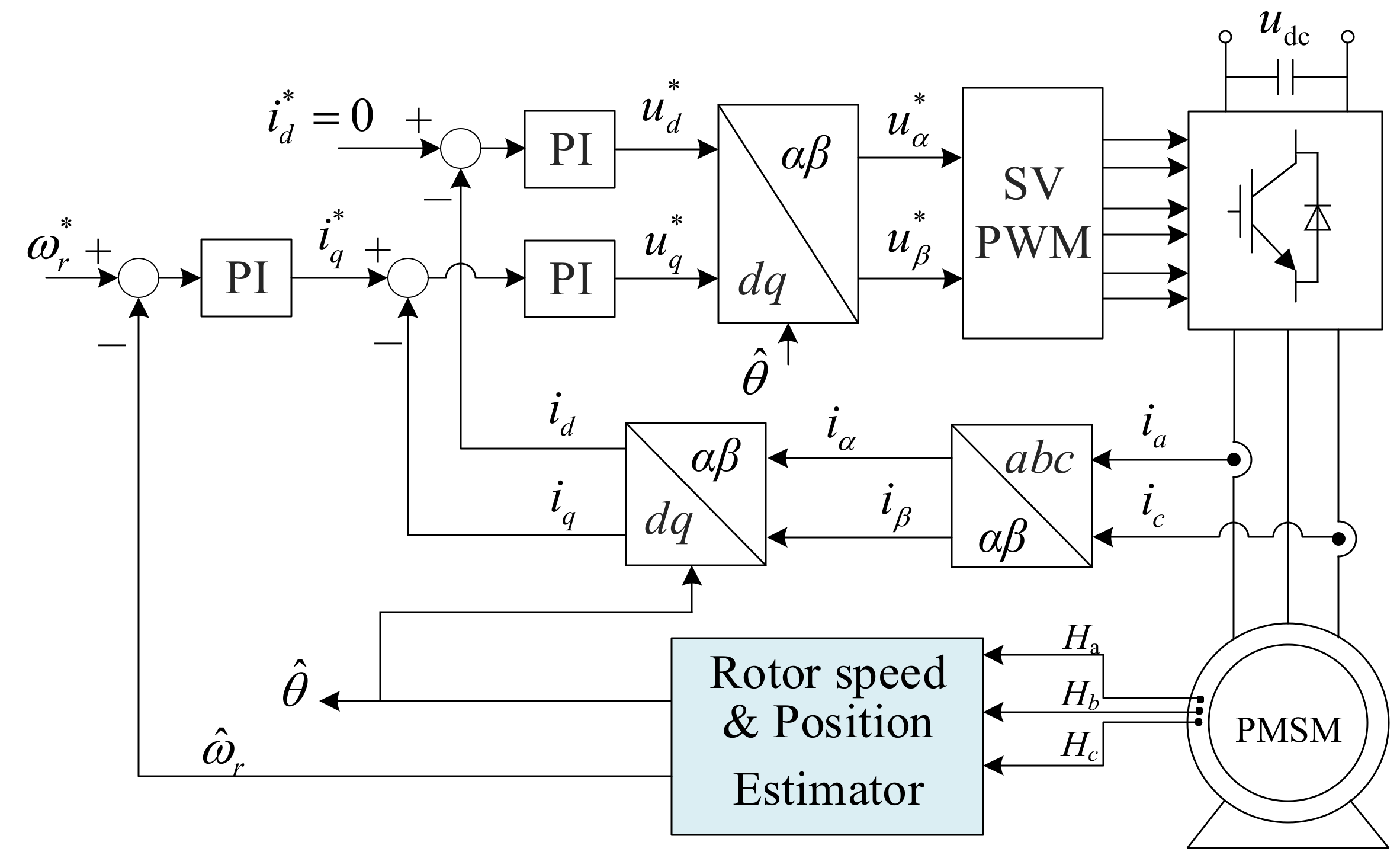
2. Field-Oriented Control of SPMSM Based on Hall-Effect Sensors

In the field-oriented control of PMSM, the direct and quadrature axis currents can be obtained and controlled independently by using the measured three-phase currents and coordinate transformation, and excellent control performance can be achieved. The surface mounted PMSM (SPMSM) has the characteristic of equal d and q axis inductances due to the symmetrical magnetic circuit. When the id = 0 control is adopted, all the current can be controlled to generate electromagnetic torque by controlling the d-axis current to zero, and the maximum torque per ampere control of SPMSM can be realized. In this control scheme, it is necessary to have a precise angle of rotor flux, which can be obtained by detecting the position of the rotor. Generally, the position sensors are a rotary transformer and a photoelectric encoder. In volume-limited systems, the Hall-effect sensors are commonly used to detect the rotor position and speed, and the field-oriented control of the PMSM drive based on the Hall-effect sensors is shown in Figure 1.
Inside the PMSM, three Hall-effect sensors are placed on the stator at intervals of 120 electrical degrees. When the rotor rotates, the Hall-effect sensors output three square wave signals along with the change of magnetic field, and the frequency of Hall signals is positively correlated with the speed. With the help of certain estimation methods, the rotor position and speed can be obtained according to the Hall signals and used in the FOC consequently.

3. Conventional Rotor Position Estimation Methods

3.1. Average Speed Method

The interpolation is a common method in the function fitting of discrete data points. All the data for the whole interval can be obtained through the known data points. According to the different fitting functions, the interpolation methods used for Hall signal processing are usually divided into average speed method, average acceleration method and least squares method. In practical applications, the most widely used one is the average speed method for easy implementation, in which the motor speed is assumed to be a constant during one Hall state.
As mentioned above, three Hall-effect sensors are usually installed inside the stator at intervals of 120 electrical degrees. The sensors output square wave signals according to the polarity of the rotating magnets, and these signals are recorded as Ha, Hb and Hc, as shown in Figure 2, respectively. When the south magnet pole approaches, the output signal switches to low level, and otherwise it turns to high level.
Due to the inertia of the rotor, the speed usually cannot change violently during a Hall state. Therefore, in the average speed method, the speed is assumed to be constant in one Hall state, and the average speed of the previous Hall state is used to calculate the rotor position inside the current Hall state by interpolation. The average speed in one Hall state can be calculated by
ω n = π 3 T n
where ωn is the average speed, and Tn is the time interval of one Hall state.
The edge of each Hall signal corresponds to an exact position. According to the average speed, Hall edge position, the rotor position at Tr can be calculated by
θ ( t ) = θ n + ω ( n 1 ) × T r
where θn is the position on the edge, and Tr is the running time from the Hall edge.
The position estimation strategy based on the average speed performs well in the high-speed range. However, under low-speed or dynamic situations, delay of the calculated speed will reduce accuracy of the position estimation.

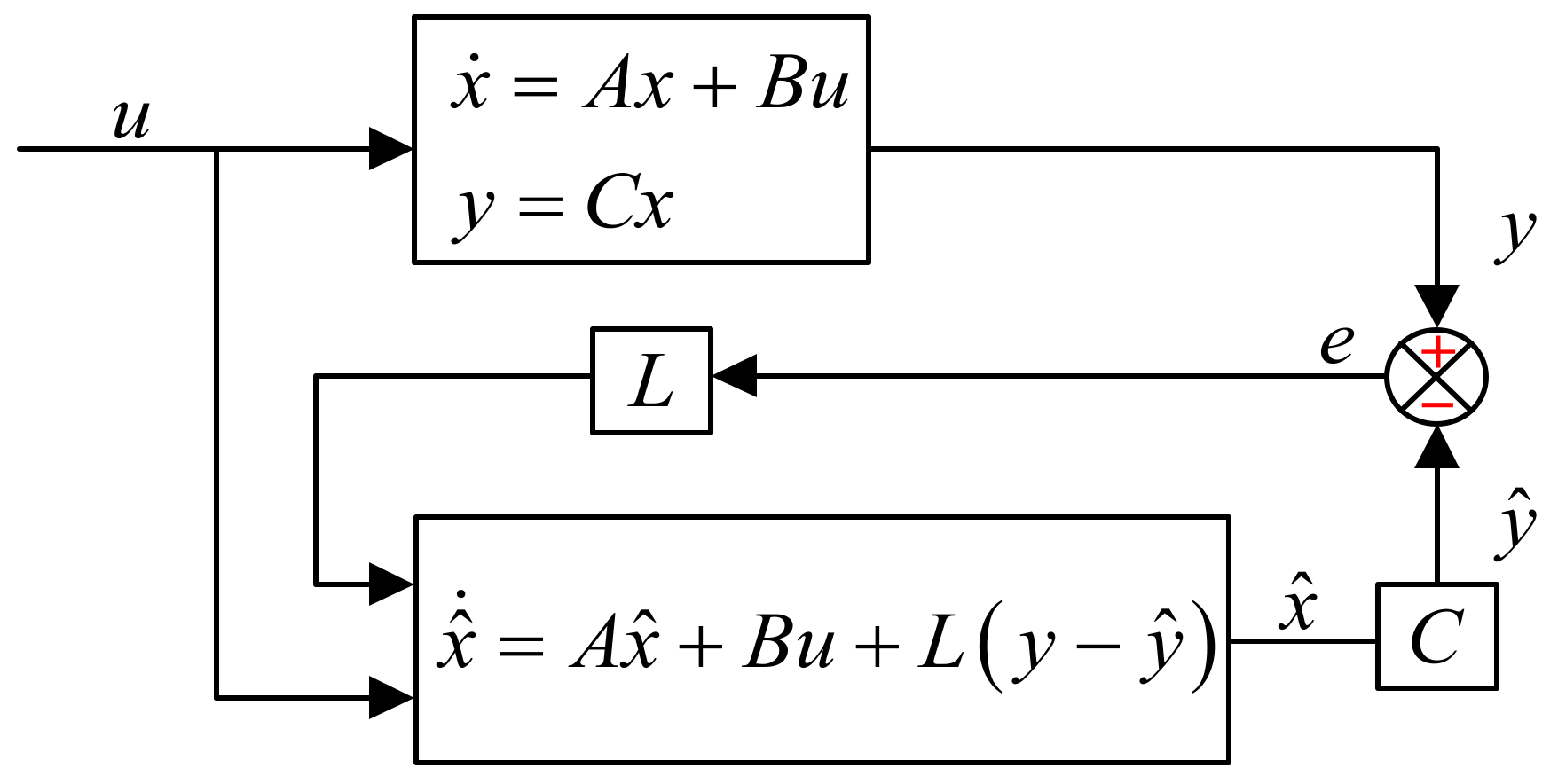
3.2. Luenberger Observer

The Luenberger observer has superior dynamic characteristics and high accuracy in estimation, and also has an intrinsic zero-delay tracking capability. The structure of the Luenberger observer is shown in Figure 3, and it constructs an observed model by using the known or measured system parameters. The output error between the observed model and the real system can converge to zero by the feedback matrix, and then model can track the real system.
The mechanical equation of PMSM can be given by
T e T L = J d ω m d t + B ω m d θ m d t = ω m = θ / P n
where Te and TL are the electromagnetic and load torque, respectively. J and B are the inertia and friction coefficient of the motor, respectively. ωm and θm are the mechanical rotor speed and position, respectively. θ is the electrical position, and Pn is the pole pairs.
Generally, B is very small and can be ignored. Thus, the mechanical equation can be rewritten as
d d t θ ω m T L = 0 P n 0 0 0 1 / J 0 0 0 θ ω m T L + 0 1 / J 0 T e θ = [ 1 0 0 ] θ ω m T L
By replacing the J of the actual system with the off-line measured value J ^ , the observer equation can be obtained as
θ ^ ˙ ω ^ ˙ m T ^ ˙ L = 0 P n 0 0 0 1 / J ^ 0 0 0 θ ^ ω ^ m T ^ L + 0 1 / J ^ 0 T e + l 1 l 2 l 3 θ θ ^
where L = l 1 l 2 l 3 T is the state feedback gain matrix, and ^ stands for the estimated values of these variables.
The characteristic equation of the observer system matrix is
s 3 + l 1 s 2 + l 2 P n s l 3 P n / J ^ = 0
In order to ensure that the observed state variables can converge to the real value, it is necessary to let the roots of the characteristic equation be located on the left half plane. Supposing the expected poles are α, β, γ, respectively, which are located on the negative real axis, they meet α < 0, β < 0, γ < 0. Then the expected characteristic equation can be rewritten as
s 3 ( α + β + γ ) s 2 + ( α β + β γ + γ α ) s α β γ = 0
The expression of state feedback gain matrix L is
l 1 = ( α + β + γ ) l 2 = ( α β + β γ + γ α ) / P n l 3 = α β γ J ^ / P n
For convenience of calculation and analysis, α is set as a triple root (α = β = γ < 0), and the matrix L can be rewritten as
l 1 = 3 α l 2 = 3 α 2 / P n l 3 = J ^ α 3 / P n
Thus, expression of the state observer is
d θ ^ / d t = P n ω ^ m + l 1 θ θ ^ d ω ^ m / d t = T e T ^ L / J ^ + l 2 θ θ ^ d T ^ L / d t = l 3 θ θ ^
According to Equation (10), the block diagram of the Luenberger observer can be obtained, as shown in Figure 4.
The θ ^ and ω ^ m can be written as Equations (11) and (12).
θ ^ = J ^ l 1 s 2 + J ^ P n l 2 s P n l 3 J ^ s 3 + J ^ l 1 s 2 + J ^ P n l 2 s P n l 3 θ + P n s J ^ s 3 + J ^ l 1 s 2 + J ^ P n l 2 s P n l 3 T e
ω ^ m = J ^ l ^ 2 s 2 l 3 s J ^ s 3 + J ^ l 1 s 2 + J ^ P n l 2 s P n l 3 θ + s 2 + l 1 s J ^ s 3 + J ^ 1 s 2 + J ^ P n l 2 s P n l 3 T e
when J J ^ , the gain matrix L is taken according to Equations (10)–(12) can be rewritten as
θ ^ = 3 α s 2 + 3 α 2 s α 3 ( s α ) 3 θ + P n s J ^ ( s α ) 3 T e
ω ^ m = 3 α 2 s α 3 P n ( s α ) 3 ω m + s 2 3 α s J ^ ( s α ) 3 T e
where, α can be used to adjust the observer gain. When α takes value of 50, 100 and 150, respectively, the Bode diagram of the observer are shown in Figure 5. It can be seen from the Bode diagram that the observer has the function of low-pass filtering, which can suppress the high-order harmonics in the input signal. The bandwidth increases with the increasing of α, and the dynamic response of the system improves as well. However, the ability to suppress high-frequency noises will decline. The bandwidth of the observer changes with α accordingly. In practical applications, α can be reasonably selected according to the speed range. When the bandwidth of the observer is 2 to 5 times the input signal frequency, the system can achieve both good tracking performance and suppression ability to high-frequency noises.

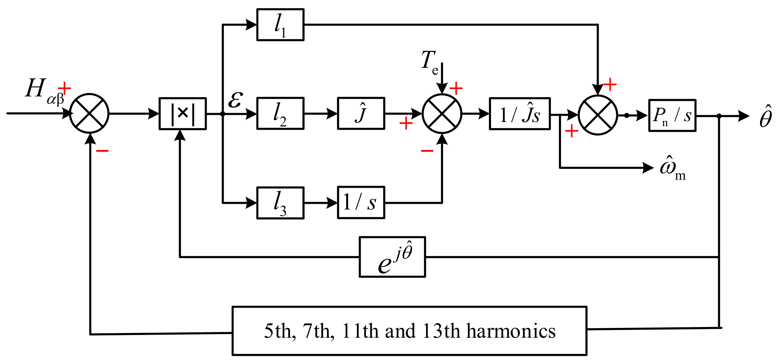
3.3. Luenberger Observer with Feedback Decoupling

Hall position and torque are required as the inputs in the Luenberger observer in order to obtain the position and speed of the motor. The torque can be calculated according to the three-phase currents, but the discrete Hall position as the input will lead to the fluctuation of observation.
The Hall position signals can be regarded as a discrete position vector rotating in space with an electrical angle increment of 60 degrees, as shown in Figure 6. If the Hall position vector is decomposed into two orthogonal components, it can be written as follows:
H = e j Δ θ = H α + j H β ( Δ θ = k π / 3 , k = 0 , 1 , 2 )
where H is the hall position vector, Hα and Hβ are two orthogonal components. The Hall vector transformation is implemented by
H α H β = 1 1 2 1 2 0 3 2 3 2 H a H b H c
The Fourier transform of Hα and Hβ can be expressed as
H α = n = 1 1 n π 1 + cos n π 3 cos 2 n π 3 cos ( n π ) sin ( n ω t ) = 3 π sin ( ω t ) + 3 5 π sin ( 5 ω t ) + 3 7 π sin ( 7 ω t ) + 3 11 π sin ( 11 ω t ) +
H β = n = 1 3 n π sin n π 3 + sin 2 n π 3 cos ( n ω t ) = 3 π cos ( ω t ) 3 5 π cos ( 5 ω t ) + 3 7 π cos ( 7 ω t ) 3 11 π cos ( 11 ω t ) +
Thus, their fundamental components can be regarded as two-phase orthogonal sine and cosine signals, as shown in Figure 7.
When the components of the input are known, the low-order harmonics can be reduced by using harmonic feedback decoupling. The improved observer structure is shown in Figure 8. According to the phase angle at the moment, the 5th, 7th, 11th and 13th harmonics are directly calculated and fed back to the input. The low-order harmonics are subtracted from the input, and the remaining high-order harmonics can be well suppressed by the low-pass filtering characteristic of the observer. The function of feedback decoupling is to further increase the gain of the observer, reduce the low-frequency noises of the input, and obtain a better dynamic performance while reducing the error of rotor position estimation [29].

4. Improved Dual Observer

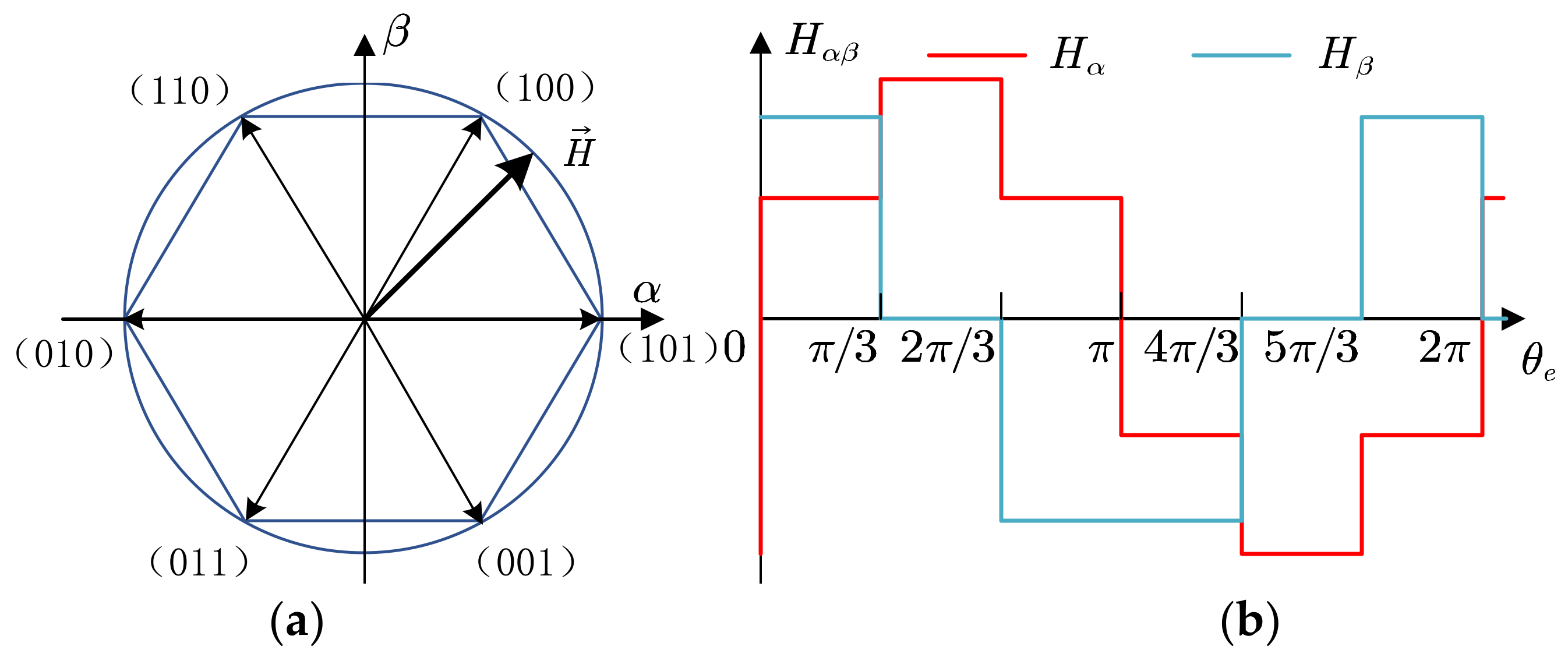
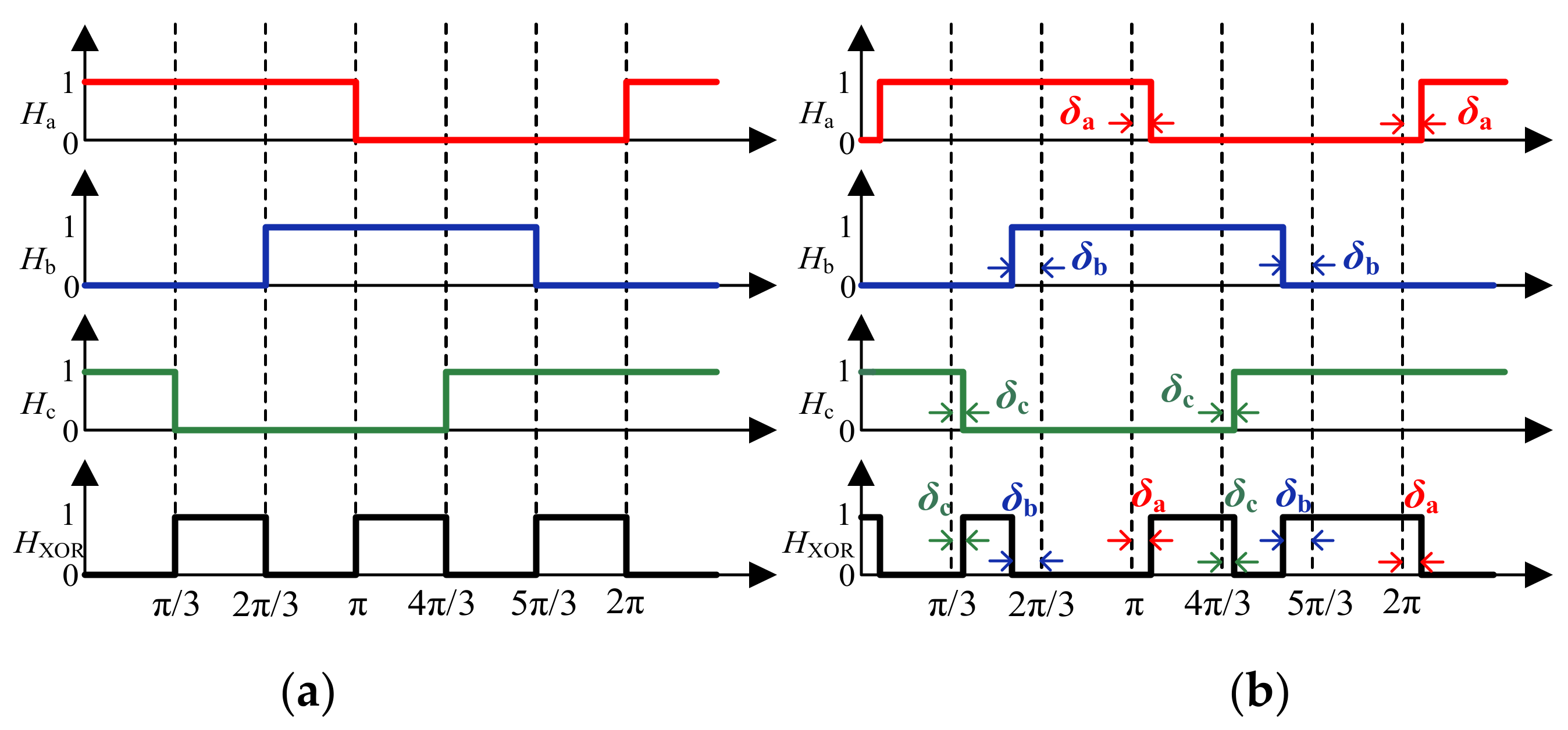
4.1. Misplaced Position Sensors

Due to the mechanical errors either in the manufacturing or assembling process, each Hall-effect sensor may be misplaced by a certain mechanical angle regarding its corresponding phase winding. There is often a certain deviation between the output signal of Hall-effect sensors and the ideal signal.
Figure 9 shows the output signals of three Hall-effect sensors when considering the deviation. In this case, the Hall states are no longer a 60° electrical angle, which will produce position and speed estimation errors. Especially when the rotor position deviates, the sinusoidity of the motor current will be seriously damaged, which will aggravate the speed fluctuation and reduce the dynamic performance.

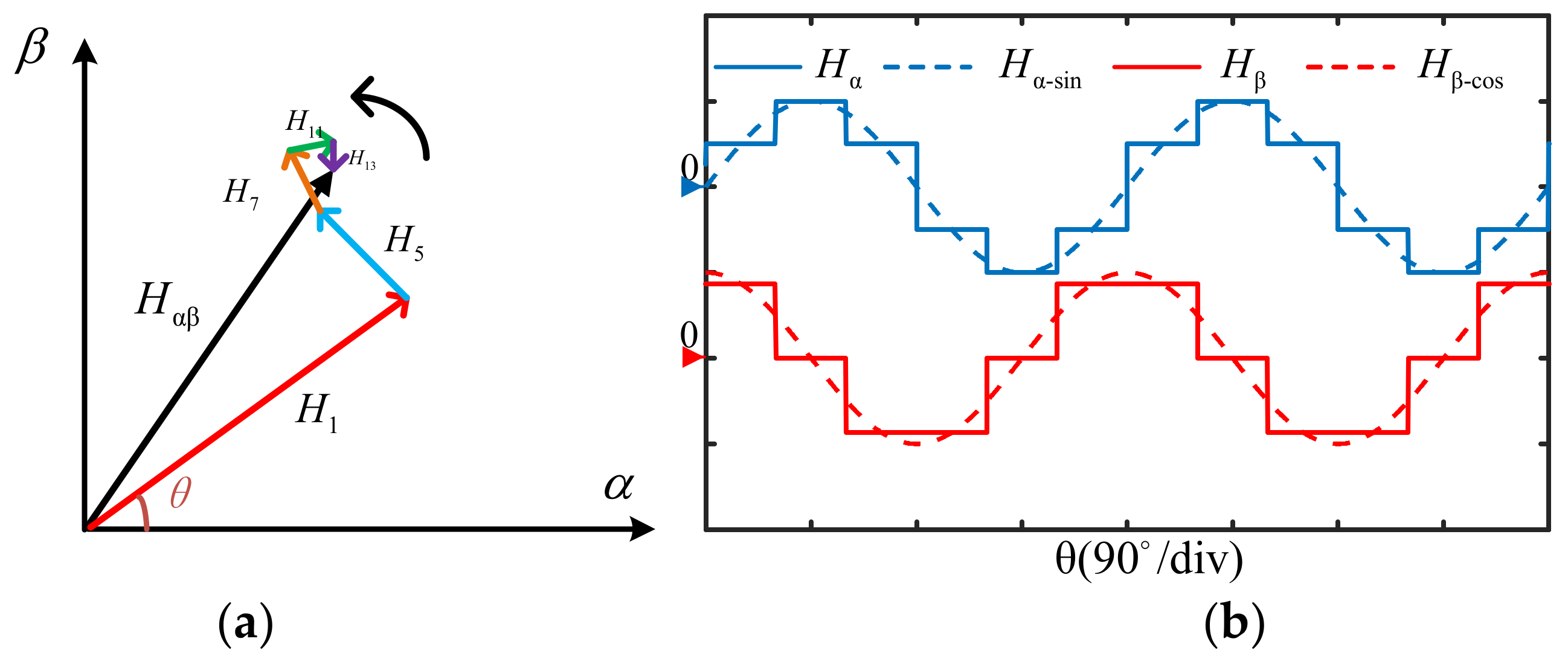
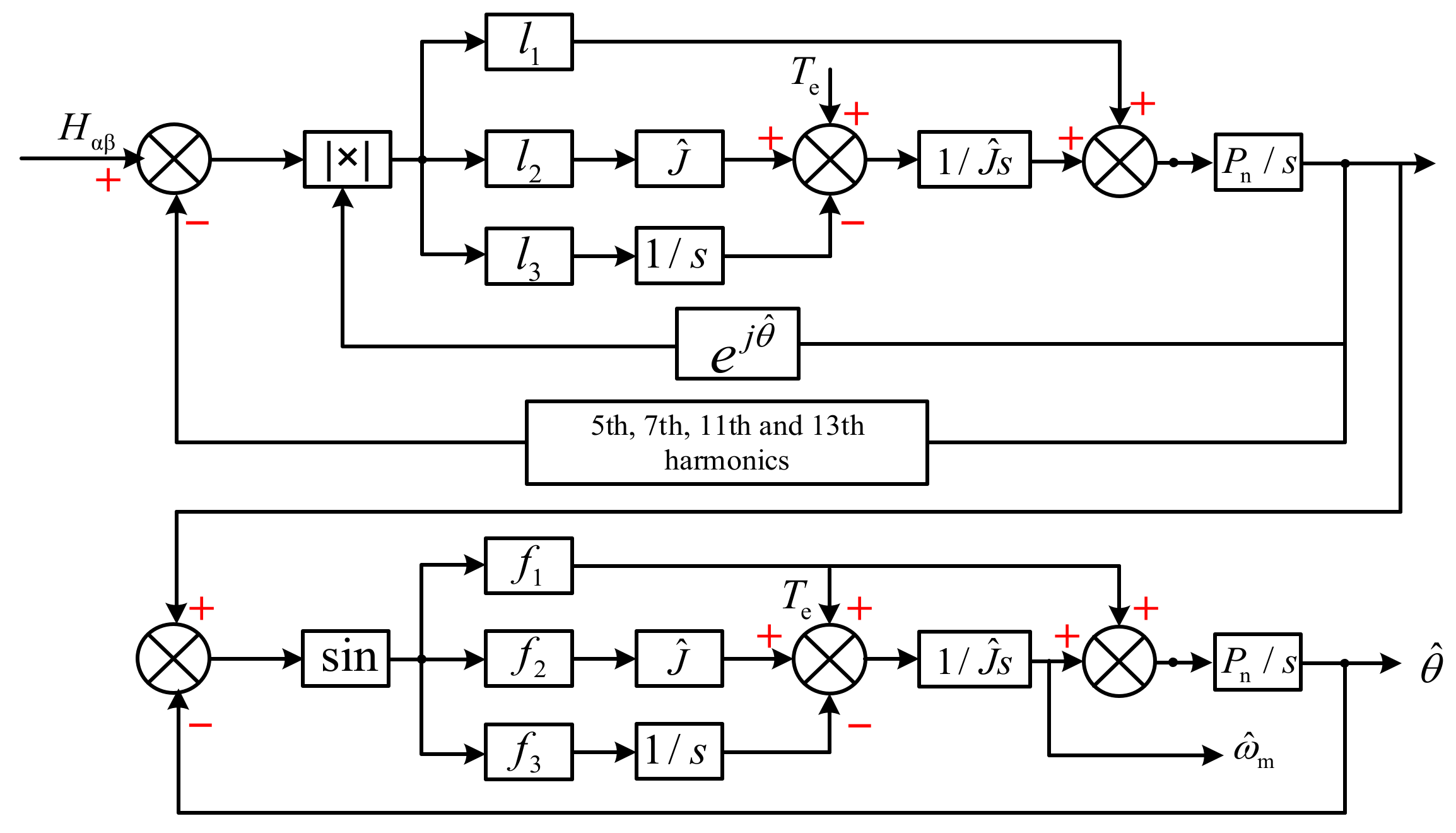
4.2. The Proposed Dual Observer

The observer with low-pass filtering property can suppress noises of the input rotor position angle. When there is a deviation in the Hall signal, the harmonics feedback decoupling can not effectively suppress the low harmonics, resulting in an error of rotor position estimation. To solve this problem, a novel position estimation method with a cascaded dual observer is proposed. By taking the rotor position obtained by the first observer as the input of the second observer, the low-order harmonics can be further suppressed, and the influence of deviation will be reduced significantly. The block diagram of the dual observer is shown in Figure 10, where F = f 1 f 2 f 3 T is the state feedback gain matrix of the second observer.
In the first observer, the 5th, 7th, 11th and 13th harmonics are fed back to the input, and the obtained position is used as input of the second observer. Through the feedback decoupling and double observers, the noises and observation errors can be reduced. The two observers have similar structure, and the same principle can be followed in parameter selection. When L = F, the dual observer can improve the observation accuracy of speed and rotor position, rather than affecting the anti-disturbance performance of the system since the same gain is chosen in the two observers.
In order to evaluate the performance of the improved observer, the observer in Figure 8 and the proposed dual observer are compared by the simulation, in which the parameters are shown as Table 1.
Figure 11 shows the estimated waveforms of rotor speed and position of the conventional Luenberger observer with feedback decoupling and the improved dual observer, respectively, when the motor runs at 1200 rpm. From Figure 11a,b, it can be seen that the observation accuracy of the Luenberger observer is affected by the Hall signal deviation. The speed estimation error is 28 rpm, and the maximum error of rotor position is 5.5° of electrical angle. The waveforms of the dual observer (α = 250) are shown in Figure 11c,d. The error in the estimated speed is significantly reduced, to about 12 rpm, and the rotor position error is reduced to within 3°.

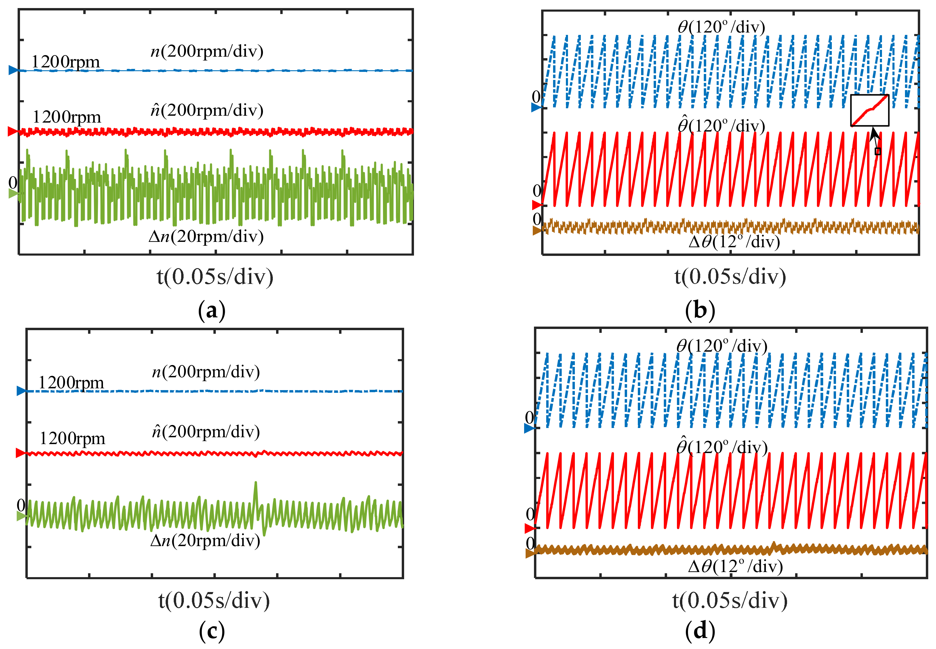
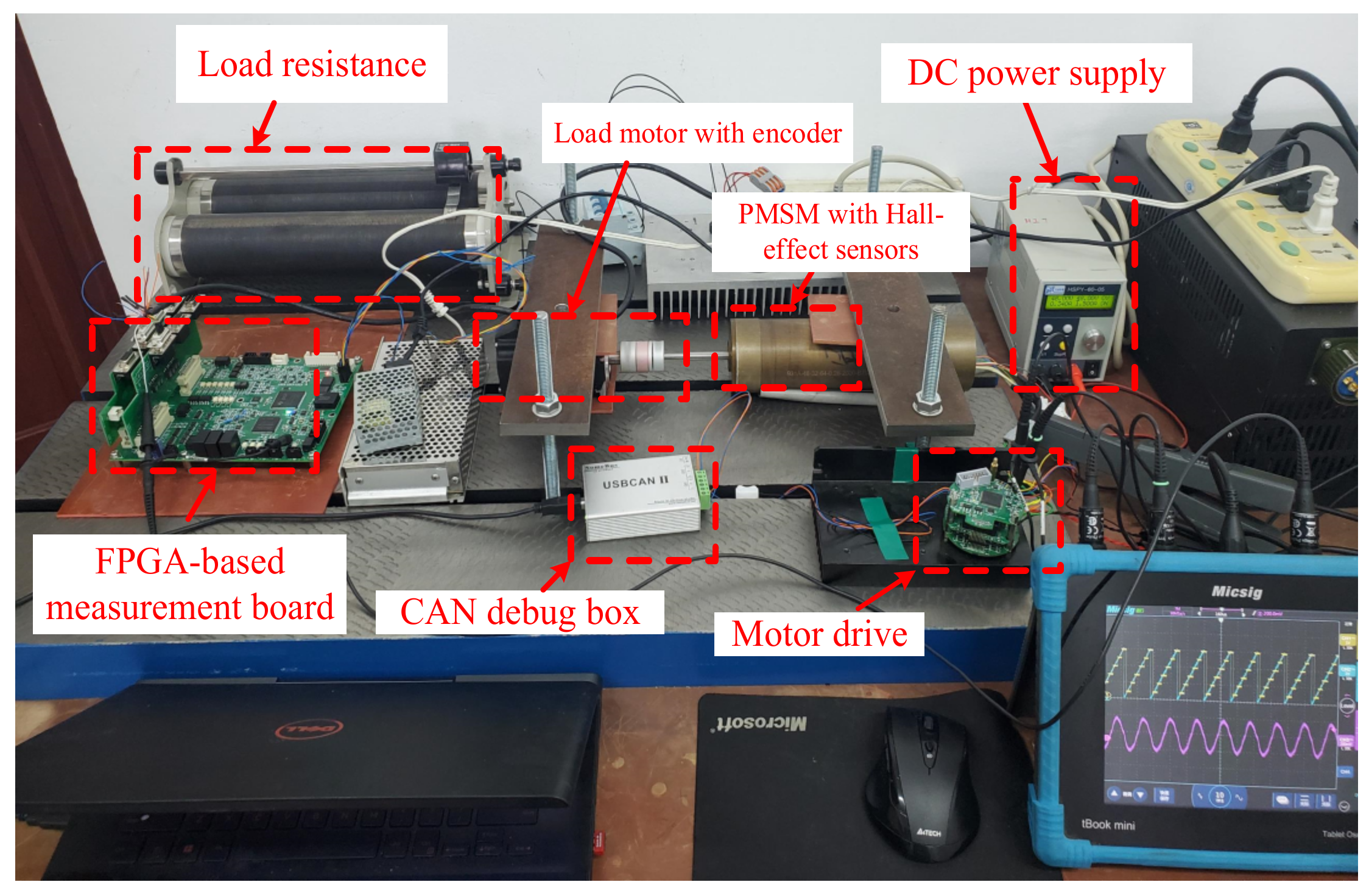
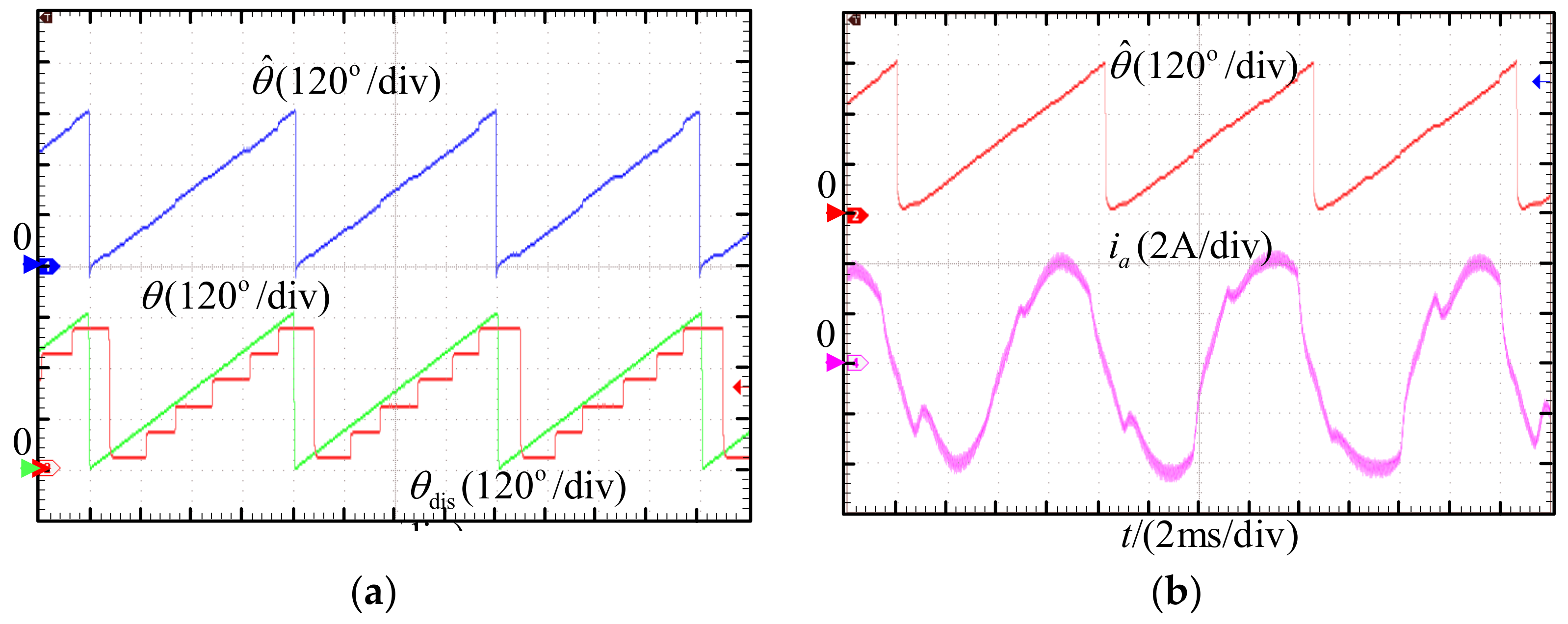
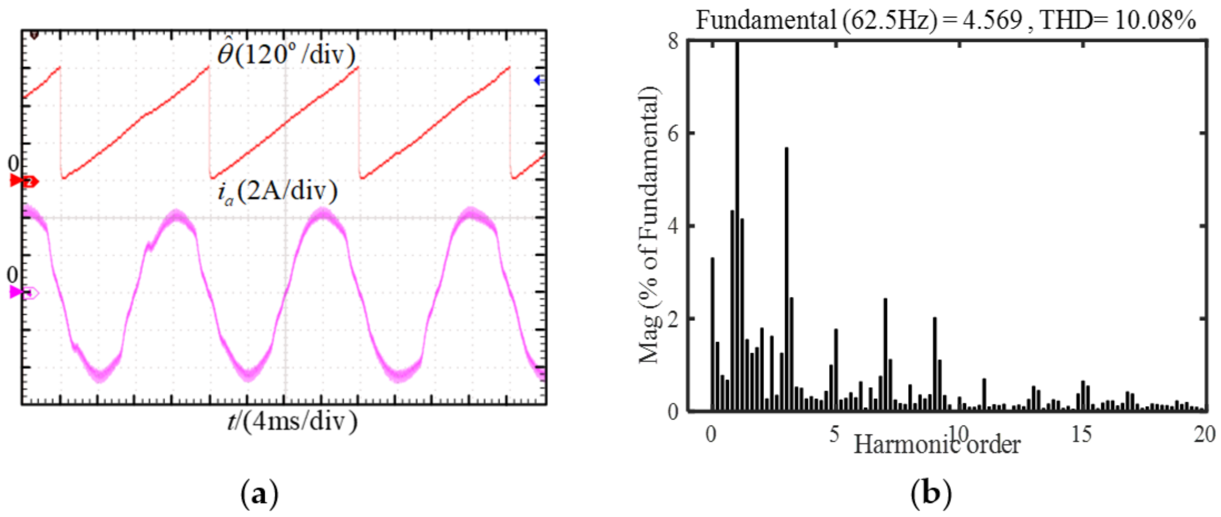
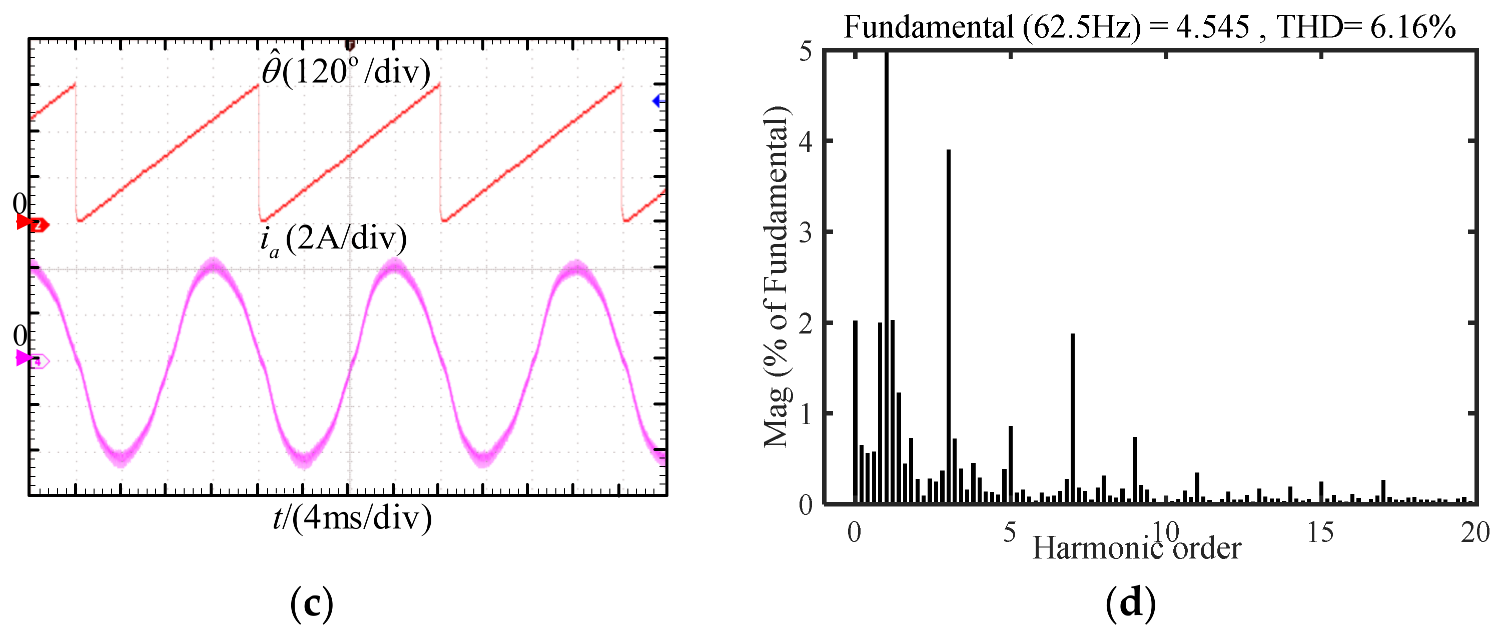
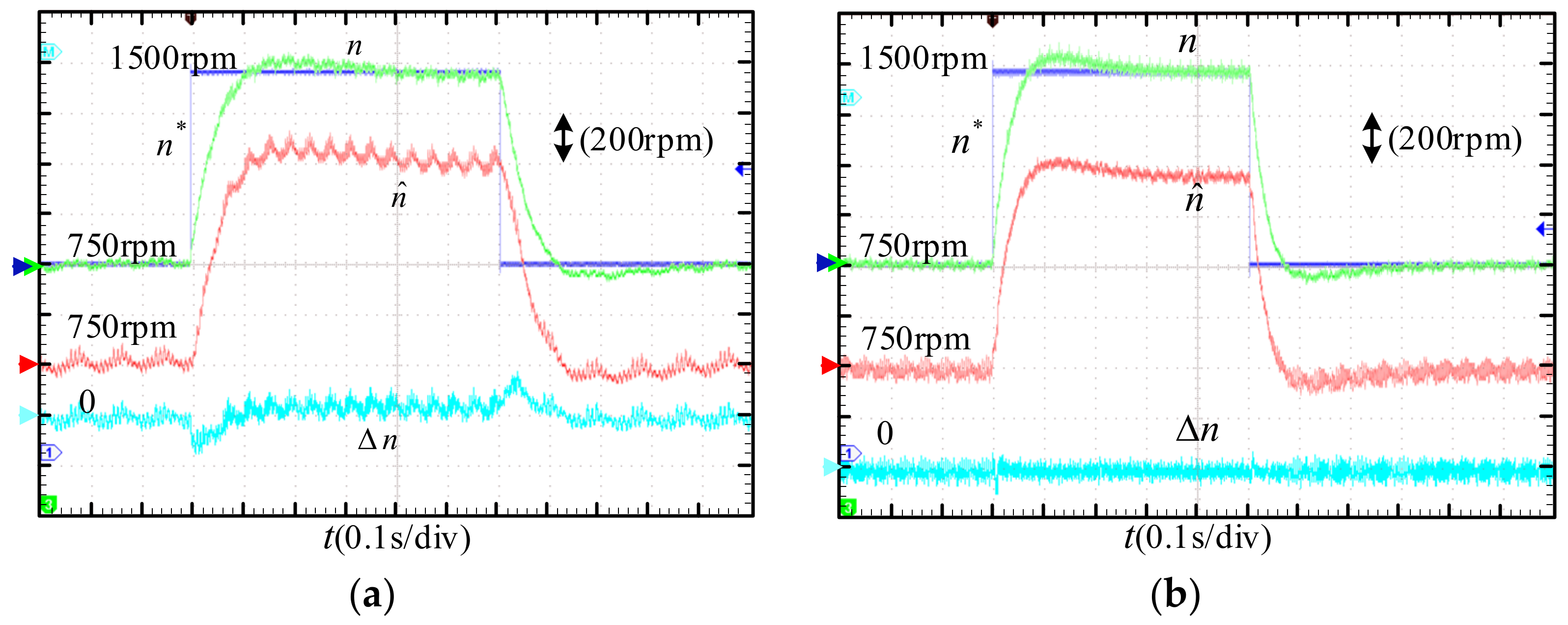
5. Experimental Verification

Experimental platform of the PMSM drive with Hall-effect sensors is shown in Figure 12. It consists of the power part, the control part and the measurement part. The power drive module is realized by a three-phase half bridge circuit composed of Infineon power MOSFET. The motor control algorithm is carried out in the TMS320F28375D chip of TI. In order to realize the accurate measurement of speed and rotor position, a 2500-line encoder and a FPGA-based measurement board are used.
Firstly, the deviation of the Hall signals of the motor is tested. When the motor rotates at an approximately constant speed and the states of Hall signals are measured as shown in Figure 13. Theoretically, the phase angle of each Hall state is 60° electrical angle, but they are unequal obviously for the test motor.
The position and motor current waveforms of the average speed method are shown in Figure 14. It can be clearly seen from Figure 14a that the estimated rotor position is unsmooth due to the misplaced Hall-effect sensors. The fluctuant rotor position will cause current distortion and increase lower harmonic components, as shown in Figure 14b.
Figure 15 shows the estimated rotor position, one phase current and its FFT analysis obtained by using the Luenberger observer with feedback decoupling and the dual observer, respectively. According to Figure 15a, when the motor runs at 750 rpm, the error of rotor position is obvious, and the current is distorted due to the error. From the FFT analysis in Figure 15b, it can be seen that the phase current contains low-order harmonics. The results obtained by the dual observer are shown in Figure 15c,d. The phase current is effectively improved and the current THD is decreased significantly.
To evaluate the dynamic performance of the proposed observer, speed step and load step responses are tested respectively. In the acceleration and deceleration experiments, the motor speed steps from 750 rpm to 1500 rpm with the 0.5 N·m load, and then steps back to 750 rpm after 0.5 s. The actual, estimated speed and their error obtained by the average speed method and the dual observer are shown in Figure 16, respectively. It can be seen that the estimated speed of the dual observer has better steady-state performance and dynamic response compared with the average speed method.
Figure 17 shows the speed and current waveforms with the load step changes. When the motor runs at 1500 rpm, the load torque suddenly decreases from 0.5 N·m to zero and then back to 0.5 N·m again. During the load step changes, the estimated speed of dual observer closely follows the measured speed. Therefore, the improved dual observer does not affect the dynamic performance of the system and can well improve accuracy of the position and speed estimations.

6. Conclusions

This paper analyzes the PMSM rotor position estimation strategy and implementation method based on the low-resolution Hall-effect sensors. In order to improve rotor position estimation accuracy, an improved dual observer scheme is proposed in this paper. By cascading two observers, the proposed scheme can effectively suppress the low-order noises introduced by the deviation of Hall signal, and consequently the estimation errors of speed and position can be reduced significantly. The experimental results show that the rotor position estimation and the current sinusoidal characteristic can be improved by the proposed scheme compared with the conventional average speed method and the Luenberger observer with feedback decoupling, and also the proposed scheme has an unattenuated dynamic performance. Along with decrease of the speed, bandwidth of the two observers can be adjusted in order to suppress lower noises and improve estimation performance.
The rotor position estimation technology based on low-resolution Hall-effect sensors is a low-cost and high-reliability drive scheme for PMSMs. The observer method with closed-loop characteristic has better tolerance to Hall sensor installation errors. It is necessary to consider how to improve estimation performance under low speed and/or speed dynamics in the following research.

Author Contributions

Data curation, M.Z.; Investigation, M.Z. and F.C.; Project administration, Q.A.; Software, M.Z. and S.L.; Supervision, Q.A.; Validation, C.C. All authors have read and agreed to the published version of the manuscript.

Funding

This research received no external funding.

Institutional Review Board Statement

Not applicable.

Informed Consent Statement

Not applicable.

Data Availability Statement

Not applicable.

Conflicts of Interest

The authors declare no conflict of interest.

References

  1. Wang, J.; Jiang, Q.; Xiong, D. Review of Rotor Position and Speed Estimation Method of PMSM with Hall Sensor. In Proceedings of the 2021 IEEE 16th Conference on Industrial Electronics and Applications (ICIEA), Chengdu, China, 1–4 August 2021; pp. 1832–1837. [Google Scholar]
  2. Morimoto, S.; Sanada, M.; Takeda, Y. Sinusoidal Current Drive System of Permanent Magnet Synchronous Motor with Low Resolution Position Sensor. In Proceedings of the IAS ’96, Conference Record of the 1996 IEEE Industry Applications Conference Thirty-First IAS Annual Meeting, San Diego, CA, USA, 6–10 October 1996; Volume 1, pp. 9–14. [Google Scholar]
  3. Capponi, F.G.; De Donato, G.; Del Ferraro, L. Brushless AC Drive Using an Axial Flux Synchronous PM Motor with Low Resolution Position Sensors. In Proceedings of the 2004 IEEE 35th Annual Power Electronics Specialists Conference (IEEE Cat. No.04CH37551), Aachen, Germany, 20–25 June 2004; Volume 3, pp. 2287–2292. [Google Scholar]
  4. Brown, R.H.; Schneider, S.C.; Mulligan, M.G. Analysis of Algorithms for Velocity Estimation from Discrete Position versus Time Data. IEEE Trans. Ind. Electron. 1992, 39, 11–19. [Google Scholar] [CrossRef]
  5. Dalala, Z.M.; Cho, Y.; Lai, J.-S. Enhanced Vector Tracking Observer for Rotor Position Estimation for PMSM Drives with Low Resolution Hall-Effect Position Sensors. In Proceedings of the 2013 International Electric Machines & Drives Conference, Chicago, IL, USA, 12–15 May 2013; pp. 484–491. [Google Scholar]
  6. Liu, G.; Chen, B.; Song, X. High-Precision Speed and Position Estimation Based on Hall Vector Frequency Tracking for PMSM With Bipolar Hall-Effect Sensors. IEEE Sens. J. 2019, 19, 2347–2355. [Google Scholar] [CrossRef]
  7. Lim, J.-H.; Park, S.M.; Hyon, B.J.; Park, J.S.; Kim, J.-H.; Choi, J.-H. Study on PMSM Rotor Position Compensation Method for Hall-Effect Sensor Installation Error Using WBG- Based Inverter. In Proceedings of the 2021 24th International Conference on Electrical Machines and Systems (ICEMS), Gyeongju, Korea, 31 October–3 November 2021; pp. 1844–1848. [Google Scholar]
  8. Bolognani, S.; Tubiana, L.; Zigliotto, M. Extended Kalman Filter Tuning in Sensorless PMSM Drives. IEEE Trans. Ind. Appl. 2003, 39, 1741–1747. [Google Scholar] [CrossRef]
  9. Batzel, T.D.; Lee, K.Y. Commutation Torque Ripple Minimization for Permanent Magnet Synchronous Machines with Hall Effect Position Feedback. IEEE Trans. Energy Convers. 1998, 13, 257–262. [Google Scholar] [CrossRef]
  10. Zaim, S.; Martin, J.P.; Nahid-Mobarakeh, B.; Meibody-Tabar, F. High Performance Low Cost Control of a Permanent Magnet Wheel Motor Using a Hall Effect Position Sensor. In Proceedings of the 2011 IEEE Vehicle Power and Propulsion Conference, Chicago, IL, USA, 6–9 September 2011; pp. 1–6. [Google Scholar]
  11. Kim, K.S.; Lee, J.H.; Lee, J.H.; Won, C.Y. Control Algorithm PMSM Using Rectangular 2 Hall Sensors Compensated by Sensorless Control Method. In Proceedings of the 2011 International Conference on Electrical Machines and Systems, Beijing, China, 20–23August 2011; pp. 1–6. [Google Scholar]
  12. Kim, S.-Y.; Choi, C.; Lee, K.; Lee, W. An Improved Rotor Position Estimation With Vector-Tracking Observer in PMSM Drives With Low-Resolution Hall-Effect Sensors. IEEE Trans. Ind. Electron. 2011, 58, 4078–4086. [Google Scholar] [CrossRef]
  13. Zhang, P.; Zhang, Q. A Controller of PMSM for Elctrical Bicycle with Hall Effect Sensors. In Proceedings of the 2016 IEEE 11th Conference on Industrial Electronics and Applications (ICIEA), Hefei, China, 5–7 June 2016; pp. 619–623. [Google Scholar]
  14. Yao, X.; Huang, S.; Wang, J.; Zhang, F.; Wang, Y.; Ma, H. Pseudo Sensorless Deadbeat Predictive Current Control for PMSM Drives With Hall-Effect Sensors. In Proceedings of the 2021 IEEE International Electric Machines & Drives Conference (IEMDC), Virtual Event. 16–18 May 2021; pp. 1–6. [Google Scholar]
  15. Giulii Capponi, F.; De Donato, G.; Del Ferraro, L.; Honorati, O.; Harke, M.C.; Lorenz, R.D. AC Brushless Drive with Low-Resolution Hall-Effect Sensors for Surface-Mounted PM Machines. IEEE Trans. Ind. Appl. 2006, 42, 526–535. [Google Scholar] [CrossRef]
  16. Harke, M.C.; De Donato, G.; Giulii Capponi, F.; Tesch, T.R.; Lorenz, R.D. Implementation Issues and Performance Evaluation of Sinusoidal, Surface-Mounted PM Machine Drives With Hall-Effect Position Sensors and a Vector-Tracking Observer. IEEE Trans. Ind. Appl. 2008, 44, 161–173. [Google Scholar] [CrossRef]
  17. Ahn, H.-J.; Lee, D.-M. A New Bumpless Rotor-Flux Position Estimation Scheme for Vector-Controlled Washing Machine. IEEE Trans. Ind. Inf. 2016, 12, 466–473. [Google Scholar] [CrossRef]
  18. Ni, O.; Yang, M.; Odhano, S.A.; Zanchetta, P.; Liu, X.; Xu, D. Analysis and Design of Position and Velocity Estimation Scheme for PM Servo Motor Drive with Binary Hall Sensors. In Proceedings of the 2018 IEEE Energy Conversion Congress and Exposition (ECCE), Portland, OR, USA, 23–27 September 2018; pp. 6967–6974. [Google Scholar]
  19. Ni, Q.; Yang, M.; Odhano, S.A.; Tang, M.; Zanchetta, P.; Liu, X.; Xu, D. A New Position and Speed Estimation Scheme for Position Control of PMSM Drives Using Low-Resolution Position Sensors. IEEE Trans. Ind. Appl. 2019, 55, 3747–3758. [Google Scholar] [CrossRef]
  20. Yoo, A.; Sul, S.-K.; Lee, D.-C.; Jun, C.-S. Novel Speed and Rotor Position Estimation Strategy Using a Dual Observer for Low-Resolution Position Sensors. IEEE Trans. Power Electron. 2009, 24, 2897–2906. [Google Scholar] [CrossRef]
  21. Zhao-yong, Z.; Zheng, X.; Tie-cai, L. FPGA Implementation of a New Hybrid Rotor Position Estimation Scheme Based on Three Symmetrical Locked Hall Effect Position Sensors. In Proceedings of the The 4th International Power Electronics and Motion Control Conference (IPEMC), IPEMC 2004, Xi′an, China, 14–16 August 2004; Volume 3, pp. 1592–1596. [Google Scholar]
  22. Zhao, Y.; Huang, W.; Yang, J. Fault Diagnosis of Low-Cost Hall-Effect Sensors Used in Controlling Permanent Magnet Synchronous Motor. In Proceedings of the 2016 19th International Conference on Electrical Machines and Systems (ICEMS), Chiba, Japan, 13–16 November; pp. 1–5.
  23. Park, Y.; Yang, C.; Lee, S.B.; Lee, D.-M.; Fernandez, D.; Reigosa, D.; Briz, F. Online Detection and Classification of Rotor and Load Defects in PMSMs Based on Hall Sensor Measurements. IEEE Trans. Ind. Applicat. 2019, 55, 3803–3812. [Google Scholar] [CrossRef]
  24. Wang, Z.; Wang, K.; Zhang, J.; Liu, C.; Cao, R. Improved Rotor Position Estimation for Permanent Magnet Synchronous Machines Based on Hall-Effect Sensors. In Proceedings of the 2016 IEEE International Conference on Aircraft Utility Systems (AUS), Beijing, China, 10–12 October 2016; pp. 911–916. [Google Scholar]
  25. Miguel-Espinar, C.; Heredero-Peris, D.; Igor-Gross, G.; Llonch-Masachs, M.; Montesinos-Miracle, D. An Enhanced Electrical Angle Representation in PMSM Control with Misplaced Hall-Effect Switch Sensors. In Proceedings of the 2020 23rd International Conference on Electrical Machines and Systems (ICEMS), Hamamatsu, Japan, 24–27 November 2020; pp. 1454–1459. [Google Scholar]
  26. Fernandez, D.; Reigosa, D.; Park, Y.; Lee, S.; Briz, F. Hall-Effect Sensors as Multipurpose Devices to Control, Monitor and Diagnose AC Permanent Magnet Synchronous Machines. In Proceedings of the 2021 IEEE Energy Conversion Congress and Exposition (ECCE), Vancouver, BC, Canada, 10–14 October 2021; pp. 4967–4972. [Google Scholar]
  27. Wu, Z.; Zuo, S.; Huang, Z.; Hu, X.; Chen, S.; Liu, C.; Zhuang, H. Effect of Hall Errors on Electromagnetic Vibration and Noise of Integer-Slot Inset Permanent Magnet Synchronous Motors. IEEE Trans. Transp. Electrif. 2022, 1. [Google Scholar] [CrossRef]
  28. Muley, N.; Saxena, A.; Chaudhary, P. Comparative Evaluation of Methods for Continuous Rotor Position Estimation Using Low Resolution Hall Sensors. In Proceedings of the 2021 National Power Electronics Conference (NPEC), Bhubaneswar, India, 15 December 2021; pp. 1–6. [Google Scholar]
  29. An, Q.; Chen, C.; Zhao, M.; Ma, T.; Ge, K. Research on Rotor Position Estimation of PMSM Based on Hall Position Sensor. In Proceedings of the 2021 IEEE 16th Conference on Industrial Electronics and Applications (ICIEA), Chengdu, China, 23–26 April 2021; pp. 2088–2094. [Google Scholar]
Figure 1. Block diagram of PMSM FOC based on Hall-effect sensors.
Energies 15 05985 g001
Figure 2. The waveforms of three Hall signals.
Energies 15 05985 g002
Figure 3. Luenberger Observer.
Energies 15 05985 g003
Figure 4. Block diagram of Luenberger observer.
Energies 15 05985 g004
Figure 5. (a) Bode diagram of the observed position with different gain α; (b) Bode diagram of the observed speed with different gain α.
Energies 15 05985 g005
Figure 6. (a) Discrete Hall position vector; (b) Two orthogonal components.
Energies 15 05985 g006
Figure 7. (a) The Hall position vector decomposition; (b) The fundamental components of Hα, Hβ.
Energies 15 05985 g007
Figure 8. Block diagram of Luenberger observer with feedback decoupling.
Energies 15 05985 g008
Figure 9. (a) Ideal Hall signals; (b) Hall signals with deviation.
Energies 15 05985 g009
Figure 10. Block diagram of the proposed dual observer.
Energies 15 05985 g010
Figure 11. (a) Speed waveforms of Luenberger observer; (b) Position waveforms of Luenberger observer; (c) Speed waveforms of the dual observer; (d) Position waveforms of the dual observer.
Energies 15 05985 g011
Figure 12. The PMSM drive experimental platform.
Energies 15 05985 g012
Figure 13. The deviation of the Hall signal state.
Energies 15 05985 g013
Figure 14. Experimental results of the average speed method. (a) Rotor position; (b) Phase current.
Energies 15 05985 g014
Figure 15. (a) Position and current with Luenberger observer; (b) FFT analysis of phase current with Luenberger observer; (c) Position and current with the dual observer; (d) FFT analysis of phase current with the dual observer.
Energies 15 05985 g015aEnergies 15 05985 g015b
Figure 16. The experimental results under step speed. (a) Average speed method; (b) Dual observer method.
Energies 15 05985 g016
Figure 17. The experimental results under step load. (a) Average speed method; (b) Dual observer method.
Energies 15 05985 g017
Table 1. Parameters of the simulation.
ParametersValue (Unit)
Polar pairs PN5
Flux ψf0.022 (Wb)
Stator resistance R0.18 (Ω)
Stator inductance L0.35 (mH)
Rated speed nN2000 (rpm)
Rated current iN7 (A)
Inertia J0.0001 (kg.m2)
Hall average deviation2 (deg)
Publisher’s Note: MDPI stays neutral with regard to jurisdictional claims in published maps and institutional affiliations.

