1. Introduction
Rotating machinery is one of the most critical types of machinery in the industry, and its long-term reliable and safe operation is essential. Vibration caused by an imbalanced rotor is the main reason for the abnormal operation of rotating machinery. Rotor dynamic balancing is the main method to reduce the vibration caused by unbalancing fault, and it is an important topic of long-term concern in industry and academia. Numerous scholars have reviewed dynamic balancing methods [
1,
2]. The classical methods of rotor dynamic balancing mainly include the influence coefficient method and the modal balancing method, which are widely used because of their simplicity and stable performance. However, in the process of balancing, many trial runs are needed, which reduces the economic benefits of the unit. In addition, because of the complexity of the process, the application of the balancing methods based on artificial intelligence [
3,
4] and empirical technology [
5] is limited. To improve the balancing efficiency, academics have proposed numerous trial-weight-free balancing methods [
6].
Hundal [
7] first proposed a trial-weight-free dynamic balancing method based on modal parameters, which can obtain the accurate correction mass through a series of calculations after obtaining accurate modal and experimental data. Subsequently, many scholars conducted a series of studies on the improvement of the trial-weight-free modal balancing method [
8,
9,
10], but the above methods rely on the modal analysis of the rotor and have certain limitations in use. In order to develop an efficient and stable unbalance parameter identification method, scholars applied the finite element model to the research of the balancing method without trial weight and proposed a model-based unbalance parameter identification method. Zou et al. [
11] proposed a novel time-domain unbalanced load identification method with the finite element method together with an augmented Kalman filter algorithm. Zhao et al. [
12] proposed a balancing method based on transient characteristics, combined with dynamic load identification techniques, to identify the unbalance parameters of the rotor system. Wang et al. [
13] proposed two algorithms called the single direction algorithm and the two orthogonal direction algorithm, in order to identify the unbalance of multi-disc and multi-span rotors from the unbalanced response. Bachschmid et al. [
14] proposed a model-based method for identifying multiple faults including unbalance faults, which introduces residual plots as a visualization tool for fault identification and localization. Yao et al. [
15] proposed a single-disk rotor unbalance fault identification method based on modal expansion and optimization algorithms, which can detect the location, amplitude, and phase of unbalance faults. In addition, the paper also proposed a two-disk rotor unbalance fault identification method integrating modal expansion, inverse problem, and optimization algorithm. Shrivastava et al. [
16] proposed a model-based unbalance fault identification method using a Kalman filter and recursive least squares, which requires the location of the unbalance fault to be known in advance. Sudhakar et al. [
17] proposed an improved equivalent load minimization method and vibration minimization method, and the above methods can identify the location, amplitude, and phase of a single unbalance fault with a few measurement points. Chatzisavvas et al. [
18] proposed a technique for unbalance identification based on sparse vibration measurements using the equivalent load method, which is capable of identifying the location of multiple unbalance faults without requiring a priori knowledge.
It is usually assumed that the unbalance fault occurs at the rotor disc. The accurate identification of the unbalanced fault at the disc by the model-based method proposed above needs to be based on the accurate identification of positions. When there are more discs, none of the above methods can accurately identify the location, amplitude, and phase of the unbalance, which usually happens in gas turbines, aero-engines, and other rotating equipment with multistage blades. In addition, when balancing the rotor by the above method, the balancing planes must be consistent with the planes where the unbalance faults occurs. However, in practical application, due to many restrictions, the number of balancing planes may be less than that of unbalanced faults planes, thus limiting the application of the model-based dynamic balancing method.
In this paper, a model-based balancing method without trial weight is proposed for the unbalance faults of a multi-disc rotor-bearing system. Based on the modal balance theory, we first transform the rotor unbalance into isolated unbalance on several correction planes, and then identify the above unbalance by using the model-based method. Based on the above technology, a balancing method of flexible rotor with multi-disc is proposed in this paper, which includes two processes: low-speed balancing and high-speed balancing. Numerical examples show the effectiveness and efficiency of the balancing method in reducing the rotor vibration.
This paper is organized as follows. In
Section 2, an analytical expression is established based on the modal balance theory, which theoretically shows that the unbalance of the rotor distributed in continuous or isolated form can be approximated as the equivalent isolated unbalance on several balancing planes. In
Section 3, a model-based unbalance parameter identification method is proposed which can identify the equivalent isolated unbalance on the balancing planes. The balancing process proposed is briefly described in
Section 4. In
Section 5, the balancing method proposed is simulated and verified, and the factors affecting the balancing performance are discussed. The conclusion is given in
Section 6.
2. Theory
The deformation
of a rotor with bending stiffness
and continuous mass
under an unbalanced force
can be described by the differential equation [
19]:
where
is the angular velocity of the rotor.
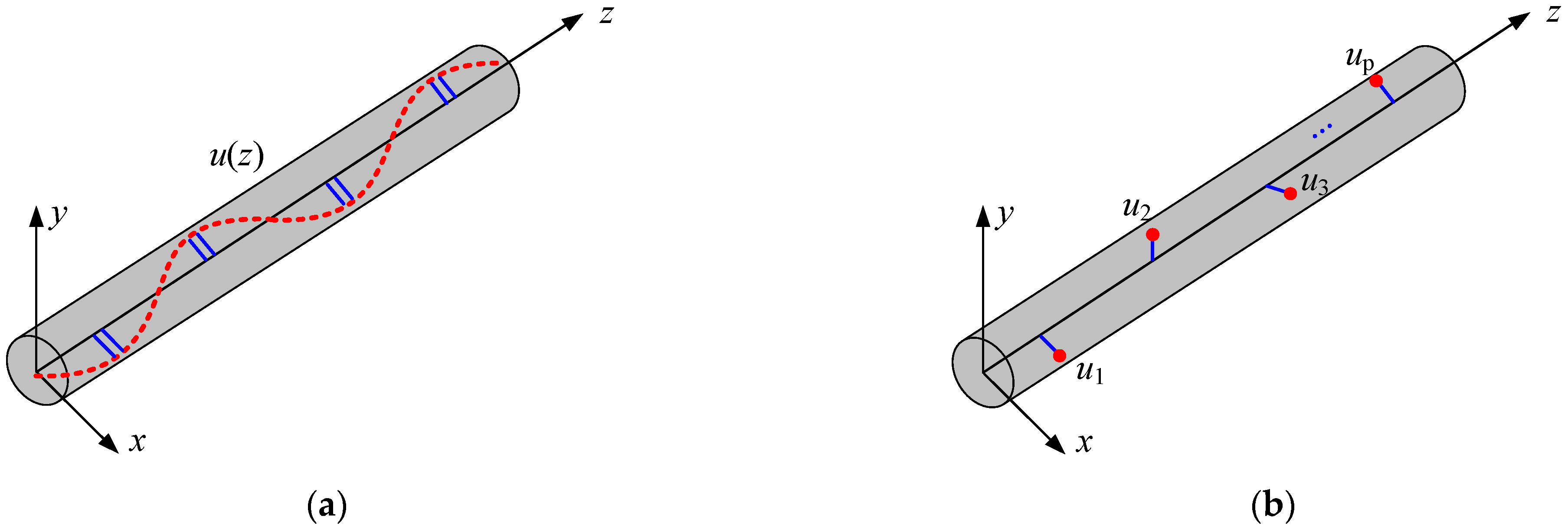
Unbalance faults are usually caused by the inconsistency between the center of mass and the center of rotation of the rotor. Rotating machinery is important equipment in modern industry. Their unbalanced distribution has two forms: isolated distribution and continuous distribution [
20], as shown in
Figure 1.
When the rotor rotates at an angular speed
, the unbalance distributed in isolated and continuous form generates an unbalance force
, which is expressed as [
19]
where the continuous unbalance
can be expanded by the principal mode in the following form
where
is the principal mode, which is the solution of Equation (1) when
.
is the nth modal component of the unbalanced distribution, and its expression is
where
is the modal mass of the
nth mode and can be expressed as
The response
of the rotor under the unbalanced force
can be expressed in the following form [
19]
According to Equation (6), we can conclude that a single isolated unbalance can excite all modes unless it happens to be located at a node of a certain mode shape without excitation of that mode. According to Equation (3), the continuous unbalance only excites the modes it contains, e.g., when , only the second order principal mode is excited.
Rotor unbalance is usually caused by manufacturing errors, assembly errors and material non-uniformity, and its distribution is complex, so it is difficult to accurately measure its distribution characteristics in practice. To solve the above problems, the purpose of this paper is to find a set of unbalance with a simpler distribution which excites a vibration response equal to the vibration response excited by the original unbalance of the system. The isolated unbalances in accordance with the characteristics of the simpler distribution form and the following discussion focuses on whether there is such a set of isolated unbalances.
Suppose there are several isolated unbalances, and the vibration caused by these unbalances is the same as that caused by the original unbalances in the rotor. The unbalance
at multiple axial positions
is used to represent the above-mentioned isolated unbalance. According to Equation (6), to make the vibration the same, the unbalance
should meet the following conditions:
When the angular velocity of rotor is lower than
, it is generally considered that the influence of modes above the
order can be ignored, i.e., it is considered that
in Equation (6) tends to 0 when
, at which time Equation (7) becomes Equation (8)
Further expanding Equation (8), the relationship between the equivalent unbalance
and the original unbalance of the system can be expressed by Equation (9)
Obviously, if and only if , Equation (9) has a solution. Therefore, we can conclude that when the rotor runs below , the original unbalance in the rotor can be approximately equivalent to the isolated unbalances in balancing planes. It should be noted that any of these planes should not be located at the node of any vibration mode, which will lead to the number of unknown parameters in Equation (9) being less than the number of equations, and thus the equivalent unbalance can not be solved.
3. Identification of Equivalent Unbalance
Due to the unknown of the right side in Equation (9), the traditional modal balancing method requires several runs for adding trial weights to complete the balancing of the rotor, which greatly reduces the efficiency. To improve the efficiency, the model-based unbalance parameter identification method has been greatly developed in recent years. It can estimate unbalance parameters according to the response signals collected in one run. This section introduces the identification of the equivalent unbalance by using the model-based method.
The equation of motion of a flexible rotor can be written as [
21]:
where
,
,
, and
are the mass, damping, stiffness, and gyroscopic matrices, respectively,
is the displacement vector of the nodes, and
is the unbalanced force vector.
To improve solution efficiency and even the unsolvable solution due to the large dimensionality of the finite element model, the reduced-order model is used to establish the equivalent unbalance solution model. The Iterated Improved Reduced System (IIRS) method proposed by Choi et al. [
22] is an effective technique for obtaining condensed matrices. We can obtain the exact characteristic properties of the system from the condensed matrices without consuming expensive calculation costs. However, the condensed matrices of the gyroscopic matrices cannot be obtained by using the above method, so the improved IIRS method [
23] is used to reduce the order of the model of the rotor-bearing system. This method must first select the degrees of freedom (dof) to be retained. In this paper, the translational dof of the node where the equivalent unbalances and the measuring sensor is located are selected as the retained dof. The reduced-order equation of Equation (10) is [
23].
The state space form of Equation (11) is [
24]
where
is the state vector,
is the system matrix,
is the input matrix, where
is the selection matrix of unbalanced forces, the elements of the translational dof of the nodes where the equivalent unbalances are located are usually set to 1 and the others are set to 0.
is the output vector. The state output matrix
is the selection matrix of the displacement response.
is the direct transfer matrix. In this paper, it is the zero matrix because only the displacement is measured. The superscript c denotes the continuous form of the matrix.
The discrete form (denoted by the superscript
d) of Equation (12) can be expressed as [
25]
where
,
,
,
,
, where
is the sampling time for discretization.
For the zero initial condition, Equation (13) can be written as the following moving average model [
26]
where
is called the Markov parameter [
27],
,
. Equation (14) can be organized into matrix form
where
is the response vector at the measurement point,
is the unbalanced forec vector at the disk,
is the total number of sampling points. The expression of
is as follows:
Equation (15) is established to solve for the equivalent unbalanced forces. We can obtain the matrix
when the parameters of the rotor-bearing system are confirmed. We can measure the displacement response
, and arrange it to obtain the vector
. By solving Equation (15), we can obtain the vector
, which can be decomposed to obtain the equivalent unbalanced force at each moment. When a displacement transducer is used to measure the rotor vibration, all elements of the matrix
are zero. According to the Picard condition [
28], the solution of
in Equation (15) is an ill-posed inverse problem.
According to the literature [
24], the solution of ill-posed inverse problem usually has the following form
where
is the regularization parameter selected in the solution process, and in this paper the L-curve criterion [
29] is used to determine the parameter
.
After the vector
is decomposed to obtain the equivalent unbalanced forces at each moment, the amplitude and phase of the equivalent unbalanced force are extracted by using the spectrum correction method [
30]. The spectral correction method is an improved FFT method, which can improve the extraction accuracy of signal frequency, amplitude and phase.
4. Balancing Process
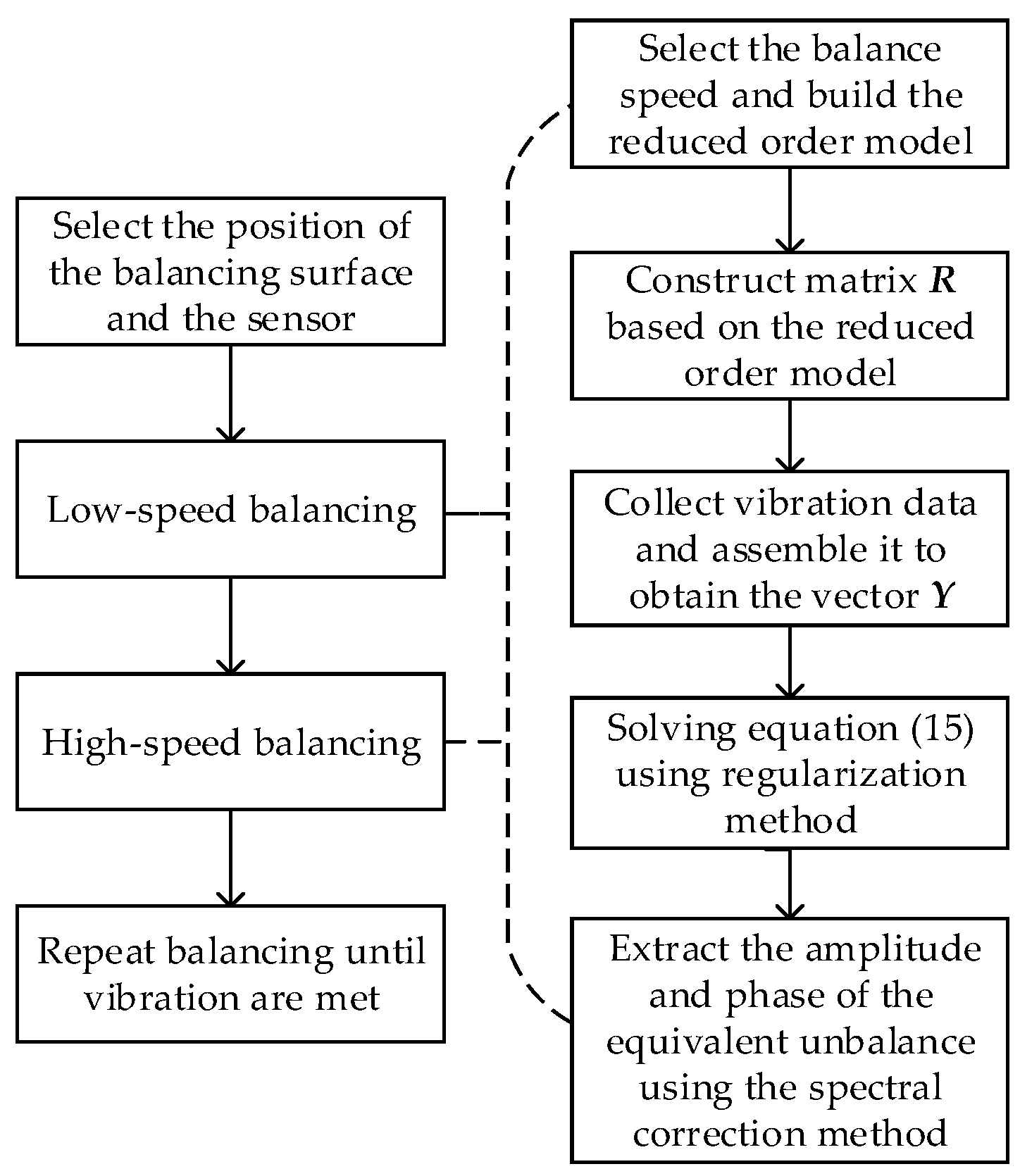
Considering the actual working condition, the unbalance may cause excessive vibration at the critical speed, which will lead to the problem that the rotor cannot safely pass the critical speed, so the low speed balancing is needed in advance. Therefore, the balancing process is set up as two processes: low-speed and high-speed balancing. The process is shown in
Figure 2. Since the processes of low-speed balance is the same as that of high-speed balance, and only the rotational speed is different, this paper takes low-speed balance as an example to illustrate the process of this balancing method.
Firstly, the balancing plane and the sensor position are selected, and then the low-speed balance shaft speed is selected to establish a reduced-order model. Secondly, construct the matrix of Equation (15) based on the reduced-order model. Thirdly, the vector of Equation (15) can be obtained by collecting and assembling the vibration data at the balanced rotating speed, and the equivalent unbalance force of the rotor-bearing system can be obtained by solving Equation (15) by the regularization method. Fourth, the amplitude and phase of the equivalent unbalance force at the balancing planes can be obtained by spectral correction. Finally, the low-speed balance of the rotor can be achieved by adding the same amount of unbalance at the opposite position of the balancing planes.
5. Numerical Simulation Verification
In this section, the simulation examples of two rotor-bearing systems (with three and four discs, respectively) are used to verify the effectiveness of the proposed balancing method.
5.1. Balancing of 3-Disc Rotor
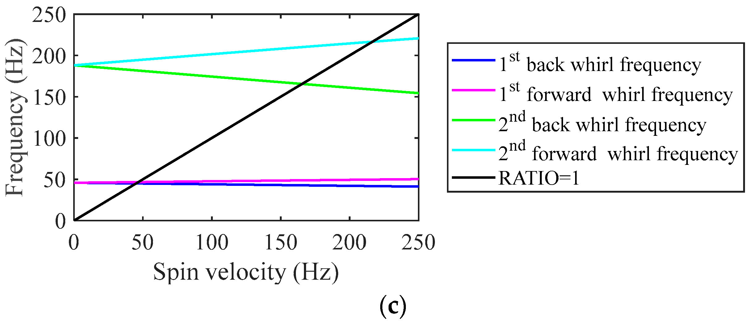
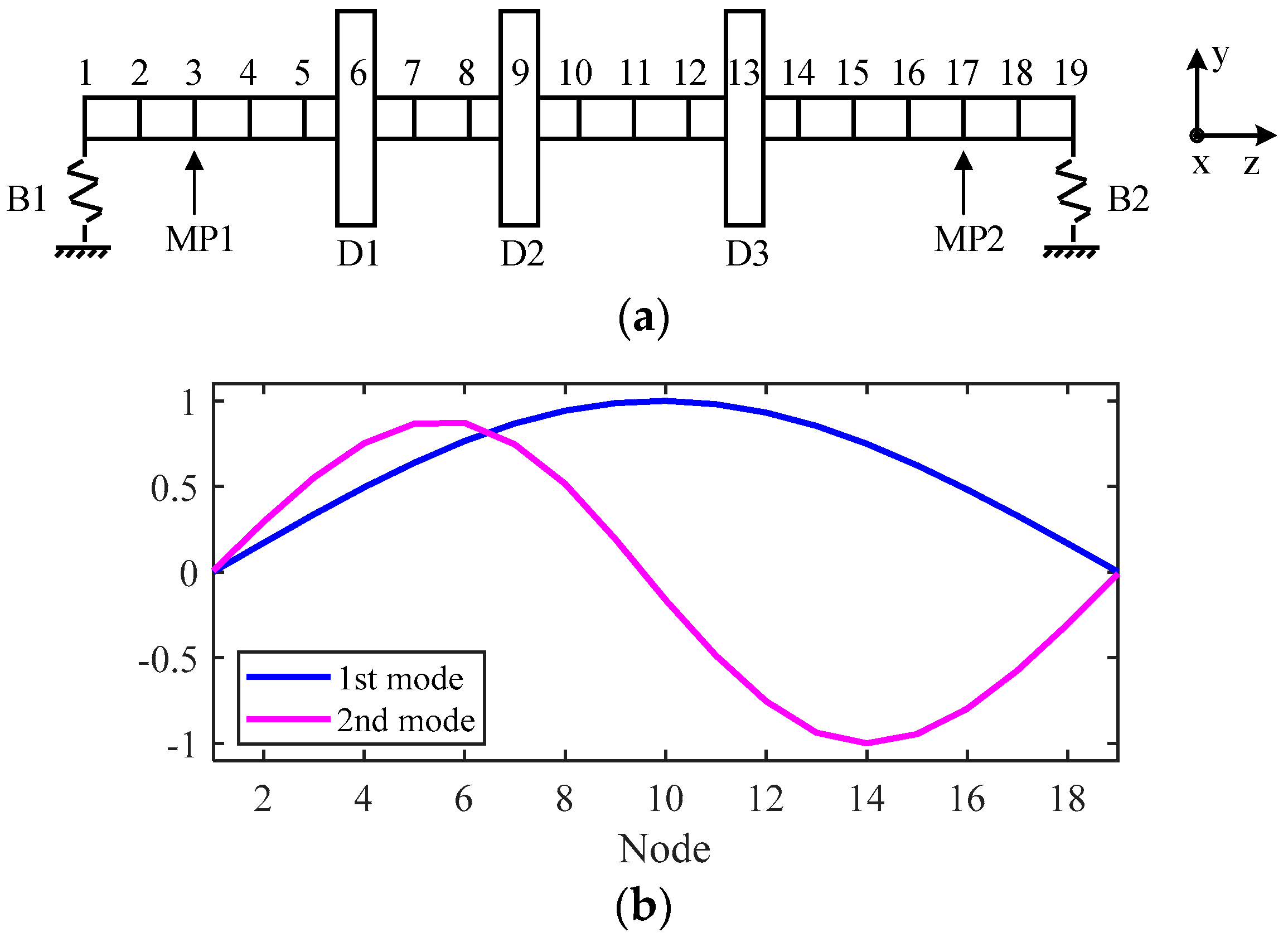
The rotor bearing system with three discs shown in
Figure 3a is selected to verify the proposed balancing method. The density of the rotor is 7850
, the elastic modulus is 2.06 × 10
11 and the Poisson ratio is 0.3. The diameter of rotor is 0.025 m and the total length is 0.72 m. The rotor-bearing system has three discs D1, D2, and D3 with the same parameters, whose mass are 8.9 kg, diameter inertia is 0.03196
, and pole inertia is 0.06392
. The distances of the three discs from the left end of the rotor are 0.24 m, 0.32 m and 0.48 m, respectively. The two bearings of the system have the same parameters and are set to be anisotropic to simulate the actual bearings. The stiffness in x and y directions is 7.5 × 10
8 N/m and 8 × 10
8 N/m and damping in x and y directions is 2 × 10
3 N∙s/m and 1.8 × 10
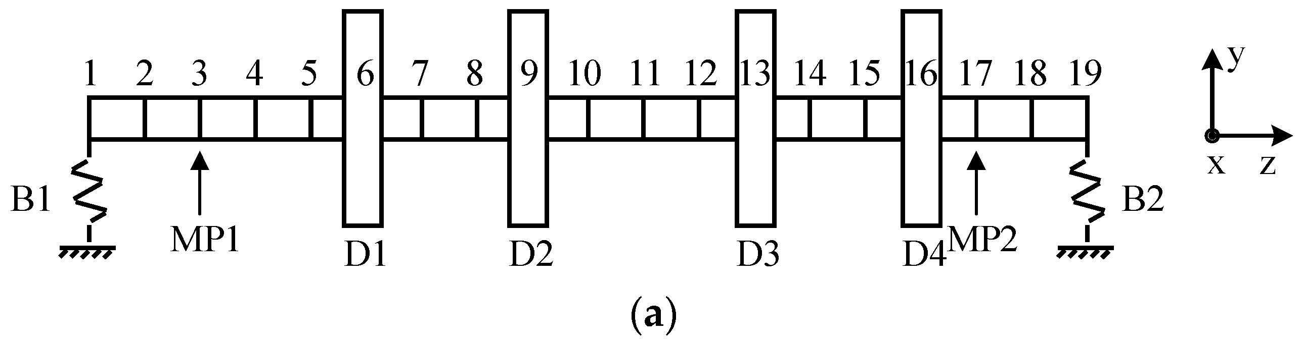
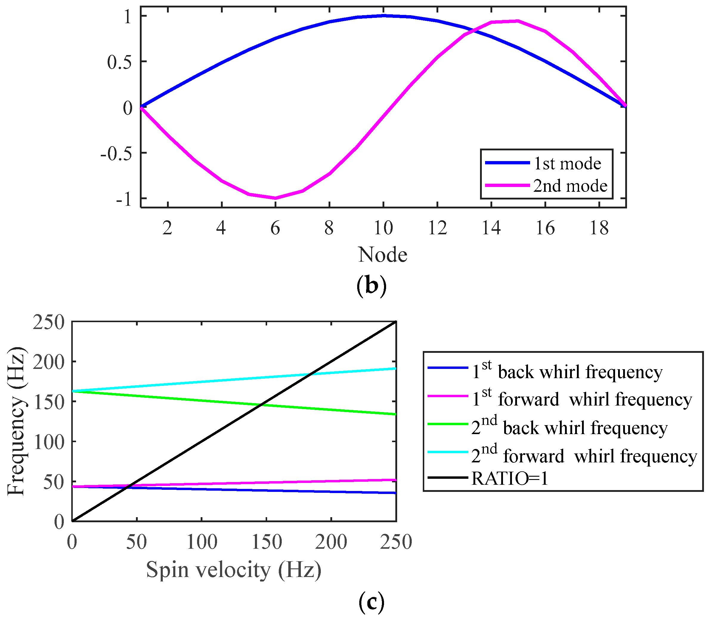
3 N∙s/m, respectively. The rotor is simulated as 18 identical Timoshenko beams, each beam has two nodes, and each node has 4 dofs: translation and rotation in X and Y directions, respectively. The finite element model has 19 nodes and 76 dofs. Three discs are located at nodes 6, 9 and 13, and two bearings are located at nodes 1 and 19. Displacement sensors are located in the x and y directions at nodes 3 and 17, respectively, to collect the vibration displacement response of the rotor.
Figure 3b shows the mode shapes of the first two orders mode of the system shown in
Figure 3a.
Figure 3c shows the Campbell diagram of this system.
Table 1 shows the first and second order synchronous forward whirl critical speed (FWCS) and synchronous back whirl critical speed (BWCS). The rotor balancing method proposed in this paper is verified by numerical simulation with the rotor operating lower than the critical speed
as an example.
In the current work, two discs located at nodes 6 and 13 are selected as balancing planes and nodes 3 and 17 are selected as the measurement position of the sensors. And the displacement responses in x and y direction are used to calculate the equivalent unbalance. According to the
Section 3, before identifying the equivalent unbalance parameters, the reduced-order model of the finite element model must be established first, and the translational dof of nodes [
3,
6,
13,
17] are chosen as the dof of the reduced-order model. Two unbalanced distribution are used to verify the reliability of the proposed method. The amplitude and phase of the unbalance are shown in
Table 2. The unbalanced masses of all three discs were placed at 0.1 m from the center of the disc.
5.1.1. Low-Speed Balancing
The effectiveness of the balancing method is verified when the unbalanced distribution is in case 1 in
Table 2. Because the unbalance may cause the rotor to vibrate too much at the critical speed, and then the rotor cannot safely cross the critical speed, it is necessary to balance at low speed. In this paper, the speed for low-speed balancing is selected as 40 Hz. The equivalent unbalance is identified by the identification method proposed in
Section 3. The length of the displacement data needs to be specified to obtain the vector
in Equation (15). In this paper, the equivalent unbalanced force is reconstructed by using the vibration displacement signal of 30 cycles and 30 sampling points in each cycle. The identification results of equivalent unbalance at discs D1 and D3 are shown in
Table 3. Calibration masses of 18.27 g and 18.13 g are added at 86.76° and −76.61° of D1 and D3 disks, respectively, for low-speed balancing.
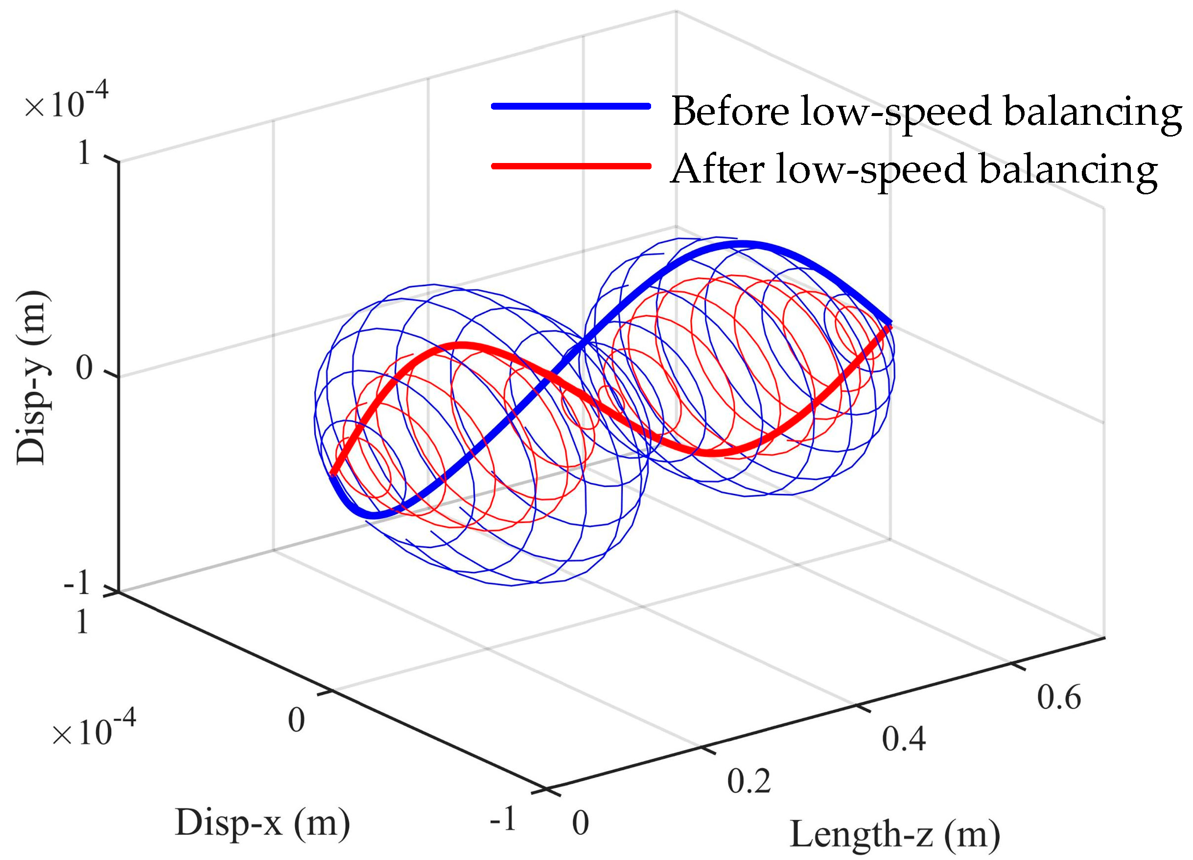
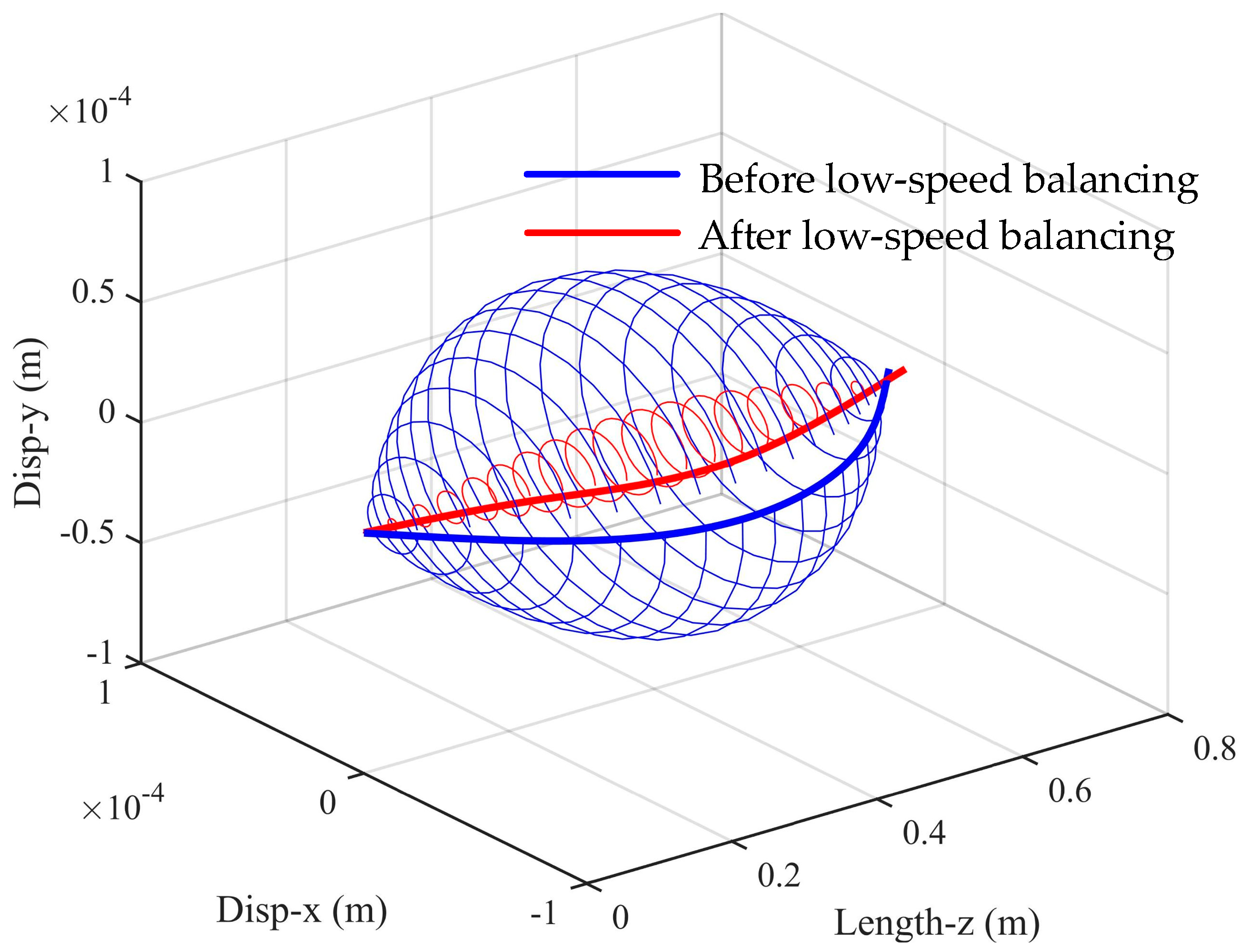
To test the effect of low-speed balancing, the steady-state unbalance response before and after low-speed balancing is calculated using the full-order model. The response is calculated using the full-order model in the subsequent part of this paper and will not be emphasized in the future.
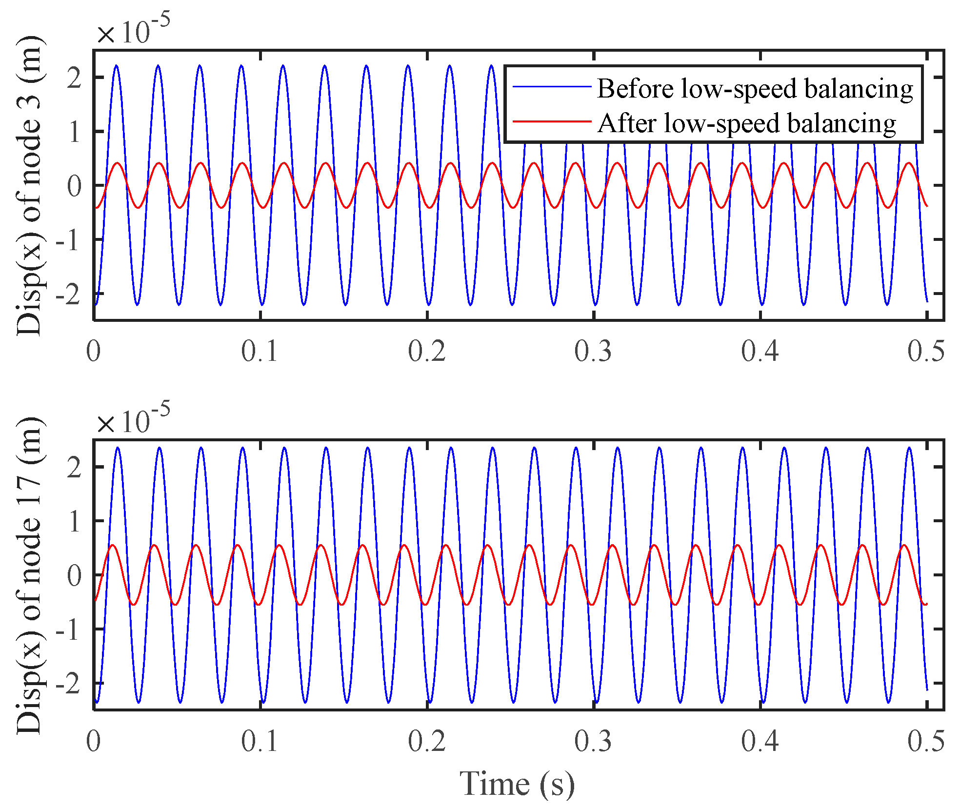
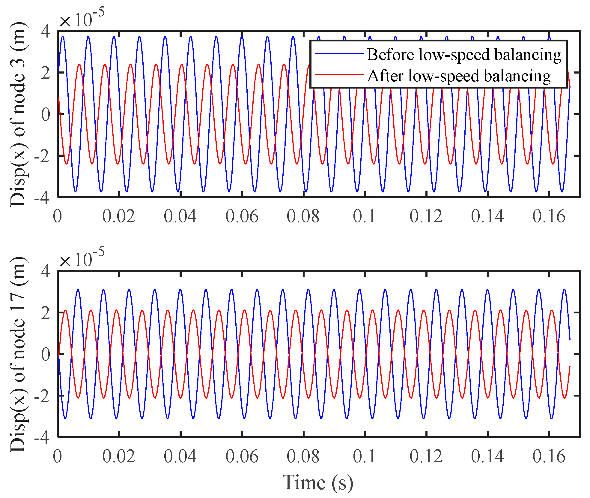
Figure 4 shows the spatial shape of the rotor before and after balancing. The amplitude of the displacement in the x-direction at nodes 3 and 17 before and after balancing at 40 Hz is shown in
Figure 5. The amplitude in the x-direction of node 3 is reduced from 2.218 × 10
−5 m to 4.139 × 10
−6 m, and the amplitude in the x-direction of node 17 is reduced from 2.364 × 10
−5 m to 5.532 × 10
−6 m, with the obvious effect of vibration reduction.
In addition, as shown in
Figure 6, the spatial shape of the rotor at 120 Hz before and after low-speed balance is also calculated.
Figure 7 shows the amplitude of the rotor at nodes 3 and 17 in the x-direction before and after low-speed balancing at 120 Hz. The amplitude of node 3 x-direction is reduced from 3.744 × 10
−5 m to 2.402 × 10
−5 m, and the amplitude of node 17 x-direction is reduced from 3.099 × 10
−5 m to 2.116 × 10
−5 m. It can be found that after low-speed balancing, the vibration response of the rotor decreases at high speed, but it is not as significant as that at low speed.
5.1.2. High-Speed Balancing
In order to further reduce the vibration of the rotor-bearing system, the rotor is balanced at high speed, and the speed of high-speed balancing is set to 120 Hz. After the correction mass for the low-speed balancing is added, the original unbalanced distribution becomes as shown in the previous column of
Table 4. The equivalent unbalances at discs D1 and D3 are identified by the identification method introduced in
Section 3. The identification results are shown in the last column of
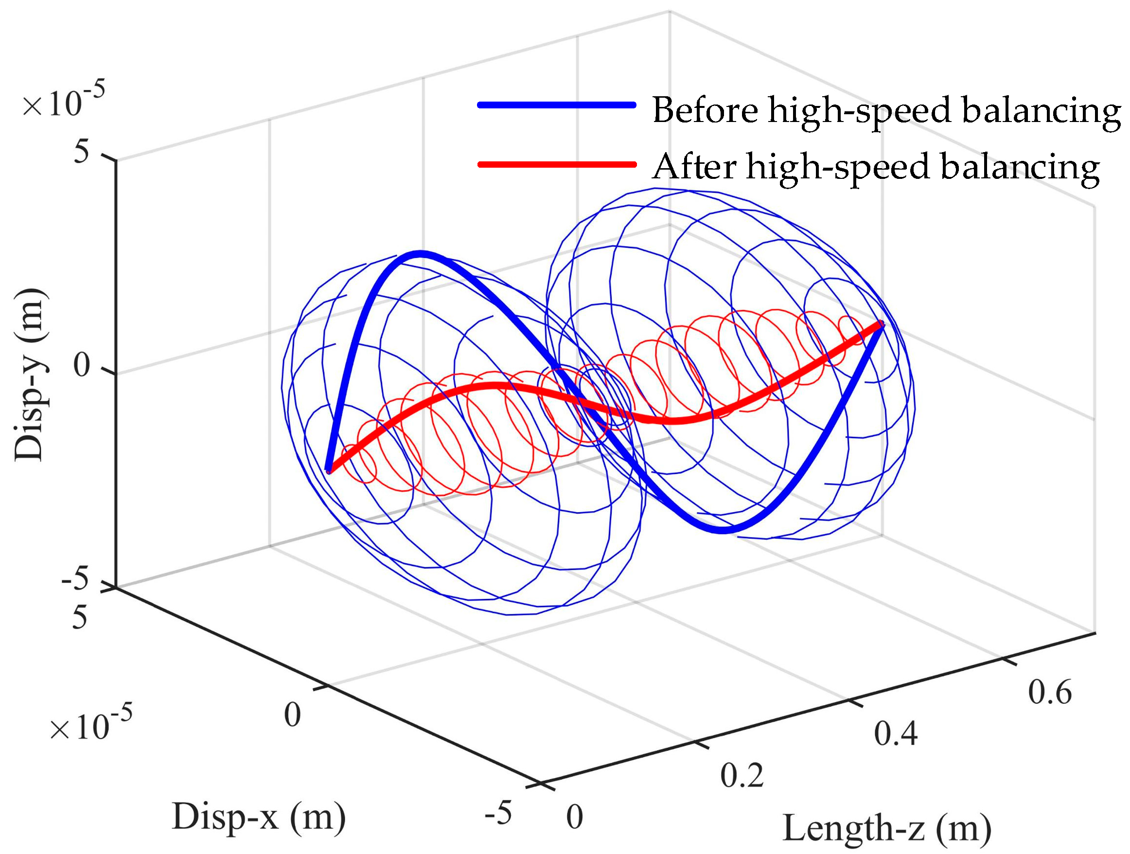
Table 4. The system is balanced at high speed by adding correction masses of 18.27 g and 18.13 g at −96.05° and −60.15° of discs D1 and D3, respectively. The steady-state response of the rotor before and after high-speed balancing is calculated. The spatial shape of the rotor is shown in
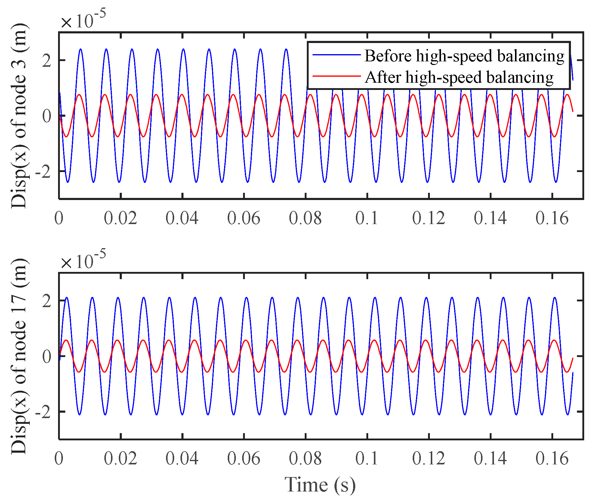
Figure 8, and the amplitude of the rotor in the x-direction at nodes 3 and 17 before and after high-speed balancing are shown in
Figure 9. The amplitude in x-direction of node 3 is reduced from 2.402 × 10
−5 m to 7.584 × 10
−6 m, and the amplitude in x-direction of node 17 is reduced from 2.116 × 10
−5 m to 5.786 × 10
−6 m, with an obvious effect of vibration reduction.
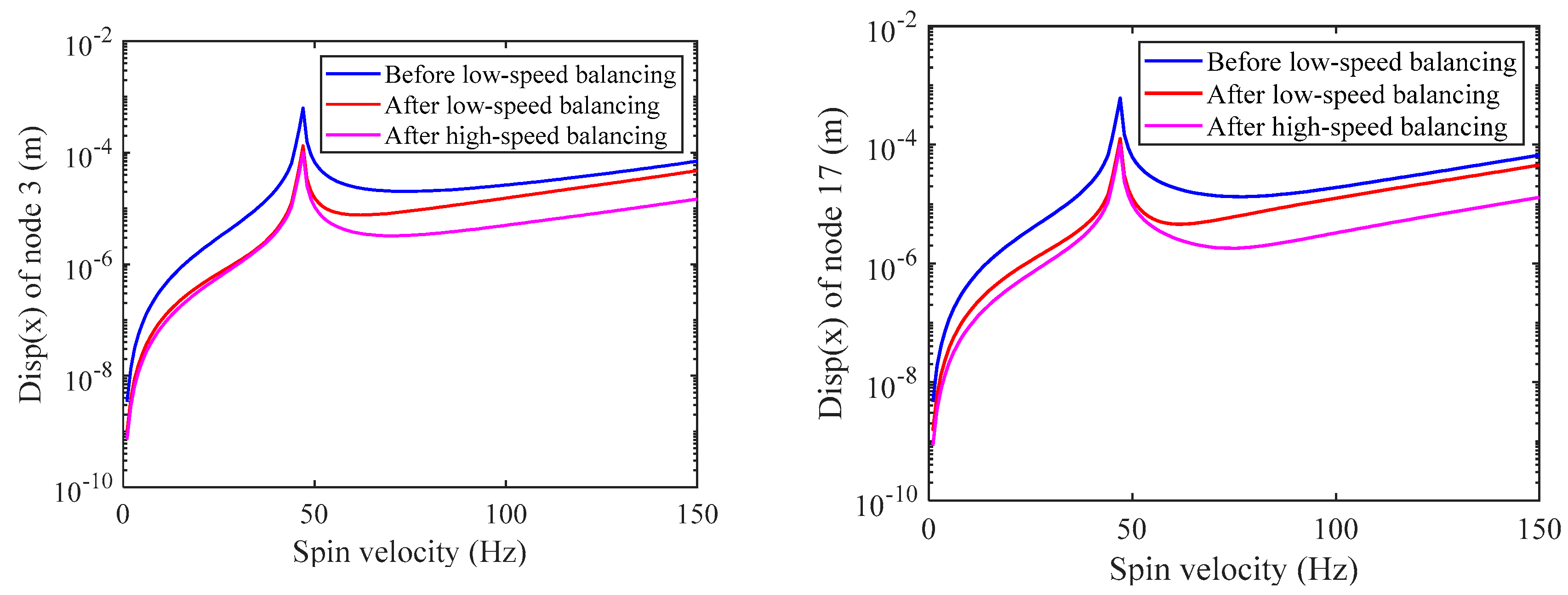
Figure 10 shows the amplitude of the rotor’s speed-up response at node 3 and 17 x-direction after low-speed and high-speed balancing when the unbalanced distribution is case 1 in
Table 2. By comparing the amplitudes, it can be found that the balancing method proposed can effectively reduce the vibration amplitude of the rotor.
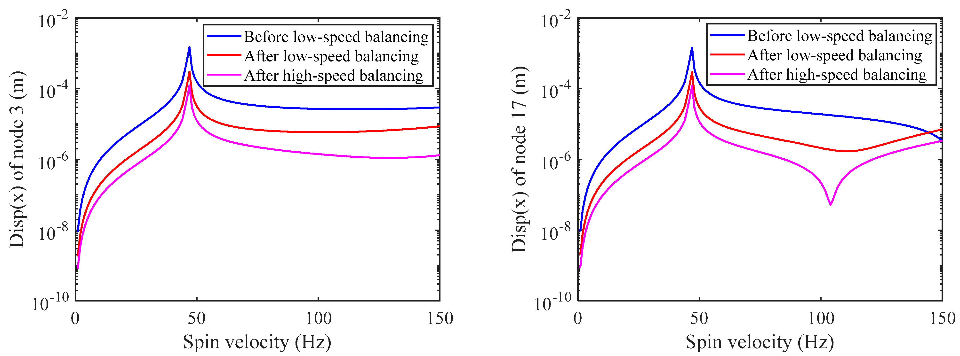
To verify the effectiveness of the proposed method for different unbalanced distributions, the unbalanced distribution is set to case 2 in
Table 2. The proposed method is used to balance the rotor-bearing system at low and high speeds. To save the space of the paper, the spatial shape of the rotor and the response at nodes 3 and 17 at the balancing speed are not listed.
Figure 11 shows the amplitude of the rotor’s speed-up response at node 3 and 17 x-direction after low-speed and high-speed balancing when the unbalanced distribution is case 2 in
Table 2. By comparing the amplitudes, it can be found that the balancing method proposed can effectively reduce the vibration amplitude of the rotor.
Table 5 summarizes the vibration amplitudes of nodes 3 and 17 in the x-direction at 120 Hz before and after balancing for different unbalance excitations (Case 1 and Case 2). The results show that the vibration amplitude of the rotor decreases by 79.74% to 95.65%, which proves the effectiveness of the balancing method.
5.2. Balancing of 4-Disc Rotor
The 4-disc rotor used for the simulation in this section is based on the 3-disc rotor in
Section 5.1, with an additional disc at node 16, and its parameters are consistent with those of other discs.
Figure 12 shows the finite element model, the modal shapes of the first two modes, and Campbell diagrams of the four-disc rotor bearing system. The first and second order FWCS and BWCS are listed in
Table 6.
The comparison between
Table 1 and
Table 6 shows that the addition of disc 4 leads to the decreases of the critical speed of the system. Therefore, the balancing speeds are set to 35 and 90 Hz in this section. The balancing goal of this section is the same as that of the three-disc rotor, that is, balancing the rotor-bearing system running below the second order critical speed
. The parameters selected in this section (including the nodes of the reduced-order model, the length of the vibration signal, and the number of sampling points per cycle) are the same as those in
Section 5.1.
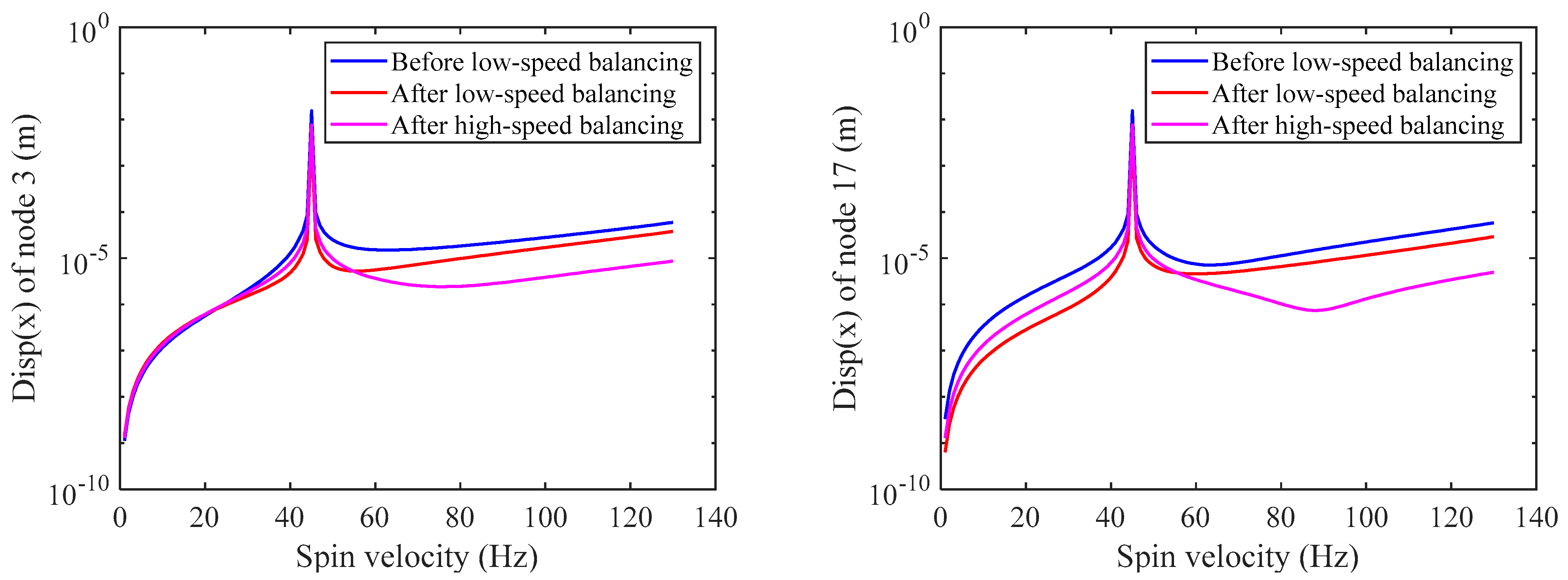
In this section, the unbalanced distribution is set to two cases, case 3 and case 4, as shown in
Table 7, to verify the balancing ability of the balancing method for rotors with different unbalanced distribution. The balancing process is the same as that of the 3-disc rotor described in
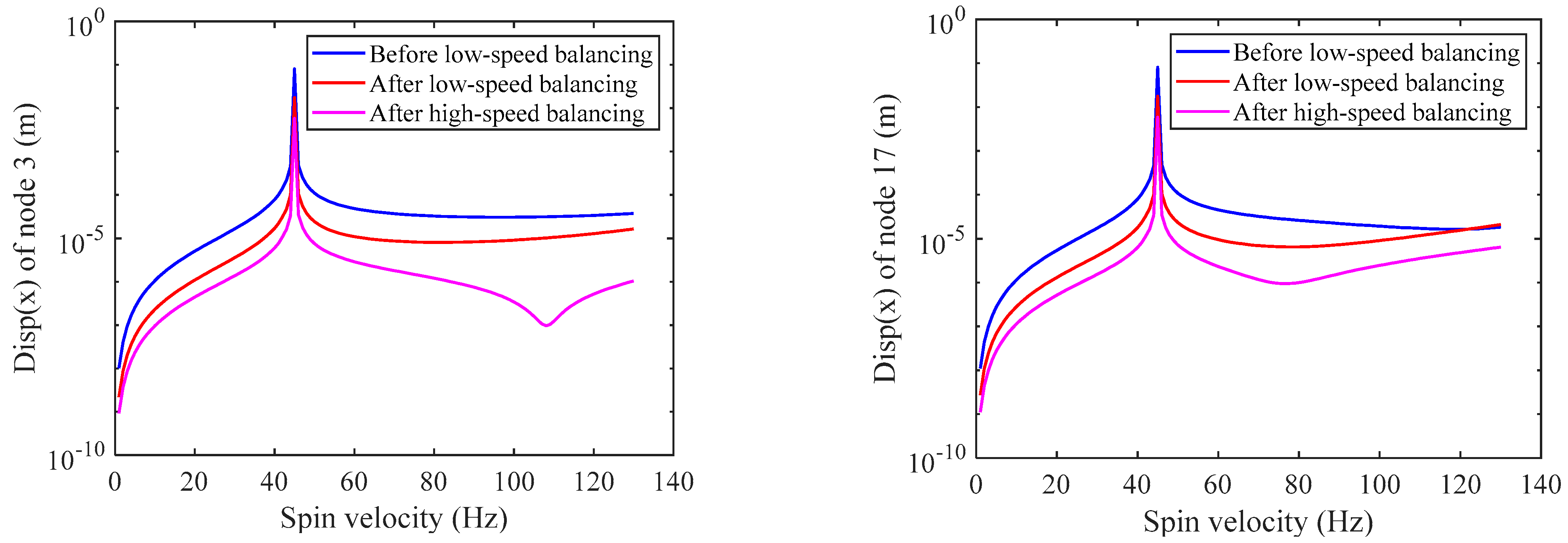
Section 5.1, and the detailed balancing process will not be described again. After low-speed and high-speed balancing,
Figure 13 and
Figure 14 show the steady-state displacement of the rotor at nodes 3 and 17 x-direction at each speed, respectively.
Table 8 shows the comparison of the displacement of the rotor at nodes 3 and 17 in the x-direction at the balancing speed of 90 Hz before and after balancing. It can be found that the vibration amplitude of the rotor is significantly reduced after the low and high-speed balancing.
5.3. Discussion
In this paper, an efficient balancing method for multi-disc rotors is proposed. Based on the modal balance theory, it is first demonstrated that the original unbalance in the rotor can be approximated as isolated unbalance on multiple balancing planes, then the model-based identification method is adopted to identify the above equivalent unbalance and, finally, the rotor balancing is completed by adding the same unbalance mass on the reverse position of the balancing planes. Considering that the actual rotor may not exceed the critical speed due to excessive vibration, the balancing process is set to low-speed balancing and high-speed balancing. From the comparison of the amplitudes of each speed before and after balancing shown in
Figure 10,
Figure 11,
Figure 13 and
Figure 14, the proposed balancing method effectively reduces the rotor vibration. From the results in
Table 5 and
Table 8, it can be seen that the amplitude at the measuring point decreases by 79.74% to 97.60%.
However, it should be noted that, in the derivation of Equations (7) to (8), we ignore the influence of modes above the
th order, but in practice, higher order modes always affect the rotor vibration response at low speeds, although this influence is small. The above reasons will lead to errors of the equivalent unbalances calculated by Equation (9), which will reduce the balancing effect. On the other hand, the accuracy of the equivalent unbalance identification method introduced in
Section 3 will also affect the balancing effect of the rotor to some extent. In extension, Equation (15) is constructed based on the reduced-order model, and the prediction accuracy of the unbalance response of the reduced-order model determines the identification accuracy of the equivalent unbalance, which in turn affects the balancing effect of this method.
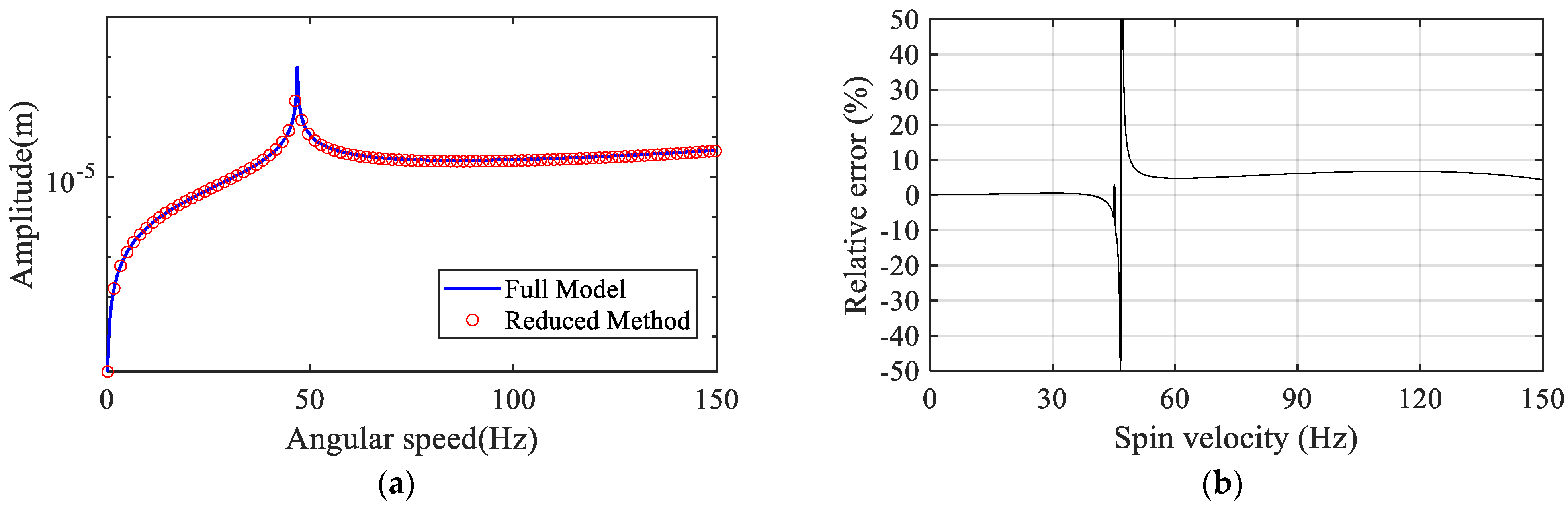
To illustrate the effect of the reduced-order model, the unbalance response of the 3-disk rotor in
Section 5.1 is predicted by the reduced-order model and the full-order model, respectively.
Figure 15a shows the comparison of the unbalance responses under the excitation of unbalance (1 × 10
−3 kg-m ∠ 135°at node 13), and
Figure 15b shows the relative error of the unbalance response predicted by the reduced-order model. It can be seen that the unbalance response predicted by the reduced-order model at different speeds is different from that predicted by the full-order model. This deviation can lead to the identification error of the equivalent unbalanced forces, which will affect the balancing effect of the proposed method. It is also to be noted that the maximum deviation occurs near the first-order critical velocity, which should not be chosen as balancing speed, otherwise, it will cause a large distortion in the equivalent unbalance identification. This implies that a more accurate equivalent unbalances identification method will help to improve the balancing effect of the rotor.
6. Conclusions
This paper proposes a multi-disc flexible rotor balancing method without trial weights. The paper first explains, based on the modal balance theory, that when the rotor operates below the th order critical speed , the unbalance, no matter how complex it is, can be approximated as isolated unbalances on balancing planes. The paper also suggests a model-based identification method to identify the equivalent isolated unbalances on balancing planes. Based on the above theory and method, the paper proposes a balancing method that includes two steps of low-speed balancing and high-speed balancing to reduce the rotor vibration caused by the unbalance. Two rotor bearing systems with three and four disks, respectively, are used to verify the proposed balancing method. The simulation results show that the amplitude in the x-direction at the measurement point decreases by 79.74~97.60% after balancing. Meanwhile, the paper analyzes the factors affecting the performance of the balancing method and concludes that the balancing effect can be further enhanced by improving the accuracy of the identification method.
The proposed balancing method can be easily applied to rotor bearing systems operating at higher speeds, although this paper verifies the balancing method by using rotors operating below second order critical speed. In the future, we will carry out further research on the improvement of the accuracy of the unbalanced parameter identification method and the experimental confirmation of the balancing method.
Author Contributions
Conceptualization, X.S. and J.C.; methodology, X.S.; software, X.S.; validation, X.S.; formal analysis, X.S.; investigation, X.S.; resources, J.C.; data curation, X.S.; writing—original draft preparation, X.S.; writing—review and editing, X.S. and Y.C.; visualization, X.S.; supervision, J.C. and Y.C.; project administration, J.C.; funding acquisition, J.C. All authors have read and agreed to the published version of the manuscript.
Funding
This research was funded by the National Natural Science Foundation of China, Grant number 52075131. The authors are grateful for the financial support.
Institutional Review Board Statement
Not applicable.
Informed Consent Statement
Not applicable.
Data Availability Statement
Not applicable.
Acknowledgments
The authors acknowledge Tan, JiuBin in Centre of Ultra-Precision Optoelectronic Instrument Engineering, Harbin Institute of Technology.
Conflicts of Interest
The authors declare that they have no conflict of interest.
References
- Li, L.; Cao, S.; Li, J.; Nie, R.; Hou, L. Review of Rotor Balancing Methods. Machines 2021, 9, 89. [Google Scholar] [CrossRef]
- Foiles, W.C.; Allaire, P.E.; Gunter, E.J. Review: Rotor Balancing. Shock. Vib. 1998, 5, 325–336. [Google Scholar] [CrossRef]
- Gohari, M.; Eydi, A.M. Modelling of shaft unbalance: Modelling a multi discs rotor using K-Nearest Neighbor and Decision Tree Algorithms. Measurement 2020, 151, 107253. [Google Scholar] [CrossRef]
- Kirk, R.G.; Guo, Z. Expert System Source Identification of Excessive Vibration. Int. J. Rotating Mach. 2003, 9, 63–79. [Google Scholar] [CrossRef]
- Smail, M.; Thomas, M.; Lakis, A. Arma Models for Modal Analysis: Effect of Model Orders and Sampling Frequency. Mech. Syst. Signal Process. 1999, 13, 925–941. [Google Scholar] [CrossRef]
- Zhou, S.; Shi, J. Active Balancing and Vibration Control of Rotating Machinery: A Survey. Shock Vib. Dig. 2001, 33, 361–371. [Google Scholar] [CrossRef] [Green Version]
- Hundal, M.S.; Harker, R.J. Balancing of Flexible Rotors Having Arbitrary Mass and Stiffness Distribution. J. Eng. Ind. 1966, 88, 217–223. [Google Scholar] [CrossRef]
- Morton, P.G. Modal Balancing of Flexible Shafts without Trial Weights. Proc. Inst. Mech. Eng. Part C J. Mech. Eng. Sci. 1985, 199, 71–78. [Google Scholar] [CrossRef]
- Delgado, E.P.; Bannister, R.H. Balancing of an Experimental Rotor without Trial Runs. Int. J. Rotating Mach. 2002, 8, 99–108. [Google Scholar] [CrossRef] [Green Version]
- Khulief, Y.A.; Mohiuddin, M.A.; El-Gebeily, M. A New Method for Field-Balancing of High-Speed Flexible Rotors without Trial Weights. Int. J. Rotating Mach. 2014, 2014, 603241. [Google Scholar] [CrossRef] [Green Version]
- Zou, D.; Zhao, H.; Liu, G.; Ta, N.; Rao, Z. Application of augmented Kalman filter to identify unbalance load of rotor-bearing system: Theory and experiment. J. Sound Vib. 2019, 463, 114972. [Google Scholar] [CrossRef]
- Zhao, S.; Ren, X.; Deng, W.; Lu, K.; Yang, Y.; Fu, C. A transient characteristic-based balancing method of rotor system without trail weights. Mech. Syst. Signal Processing 2021, 148, 107117. [Google Scholar] [CrossRef]
- Wang, A.; Bi, Y.; Feng, Y.; Yang, J.; Cheng, X.; Meng, G. Continuous Rotor Dynamics of Multi-Disc and Multi-Span Rotors: A Theoretical and Numerical Investigation of the Identification of Rotor Unbalance from Unbalance Responses. Appl. Sci. 2022, 12, 3865. [Google Scholar] [CrossRef]
- Bachschmid, N.; Pennacchi, P.; Vania, A. Identification of Multiple Faults in Rotor Systems. J. Sound Vib. 2002, 254, 327–366. [Google Scholar] [CrossRef] [Green Version]
- Yao, J.; Liu, L.; Yang, F.; Scarpa, F.; Gao, J. Identification and optimization of unbalance parameters in rotor-bearing systems. J. Sound Vib. 2018, 431, 54–69. [Google Scholar] [CrossRef] [Green Version]
- Shrivastava, A.; Mohanty, A.R. Estimation of single plane unbalance parameters of a rotor-bearing system using Kalman filtering based force estimation technique. J. Sound Vib. 2018, 418, 184–199. [Google Scholar] [CrossRef]
- Sudhakar, G.N.D.S.; Sekhar, A.S. Identification of unbalance in a rotor bearing system. J. Sound Vib. 2011, 330, 2299–2313. [Google Scholar] [CrossRef]
- Chatzisavvas, I.; Dohnal, F. Unbalance identification using the least angle regression technique. Mech. Syst. Signal Process. 2015, 50–51, 706–717. [Google Scholar] [CrossRef]
- Kellenberger, W. Should a Flexible Rotor Be Balanced in N or (N + 2) Planes? J. Eng. Ind. 1972, 94, 548–558. [Google Scholar] [CrossRef]
- Ibn Shamsah, S.M.; Sinha, J.K.; Mandal, P. Estimating rotor unbalance from a single run-up and using reduced sensors. Measurement 2019, 136, 11–24. [Google Scholar] [CrossRef]
- Zhao, S.; Ren, X.; Deng, W.; Lu, K.; Yang, Y.; Li, L.; Fu, C. A novel transient balancing technology of the rotor system based on multi modal analysis and feature points selection. J. Sound Vib. 2021, 510, 116321. [Google Scholar] [CrossRef]
- Choi, D.; Kim, H.; Cho, M. Iterative method for dynamic condensation combined with substructuring scheme. J. Sound Vib. 2008, 317, 199–218. [Google Scholar] [CrossRef]
- Sun, X.; Cui, J.; Chen, Y.; Feng, K.; Dang, H. Iterative dynamic condensation method of finite element model for rotor-bearing system. In Proceedings of the Tenth International Symposium on Precision Mechanical Measurements, SPIE 2021, Qingdao, China, 19 November 2021; Volume 12059, pp. 108–119. [Google Scholar]
- Mao, Y.M.; Guo, X.L.; Zhao, Y. A state space force identification method based on Markov parameters precise computation and regularization technique. J. Sound Vib. 2010, 329, 3008–3019. [Google Scholar] [CrossRef]
- Stelzner, A.D.; Kammer, D.C.; Milenkovic, P. A Time Domain Method for Estimating Forces Applied to an Unrestrained Structure. J. Vib. Acoust. 2001, 123, 524–532. [Google Scholar] [CrossRef]
- Wang, J.; Law, S.S.; Yang, Q.S. Sensor placement method for dynamic response reconstruction. J. Sound Vib. 2014, 333, 2469–2482. [Google Scholar] [CrossRef]
- Kammer, D.C. Input Force Reconstruction Using a Time Domain Technique. J. Vib. Acoust. 1998, 120, 868–874. [Google Scholar] [CrossRef]
- Hansen, P.C. Rank-Deficient and Discrete Ill-Posed Problems: Numerical Aspects of Linear Inversion; SIAM Monographs on Mathematical Modeling and Computation; SIAM: Philadelphia, PA, USA, 1998; ISBN 978-0-89871-403-6. [Google Scholar]
- Hansen, P.C. Analysis of discrete ill-posed problems by means of the L-curve. SIAM Rev. 1992, 34, 561–580. [Google Scholar] [CrossRef]
- Ming, X.; Kang, D. Corrections for Frequency, Amplitude and Phase in a Fast Fourier Transform of a Harmonic Signal. Mech. Syst. Signal Processing 1996, 10, 211–221. [Google Scholar] [CrossRef]
Figure 1.
Rotor unbalanced distribution (a) continuous unbalance (b) isolated unbalance.
Figure 1.
Rotor unbalanced distribution (a) continuous unbalance (b) isolated unbalance.
Figure 2.
Rotor balancing process.
Figure 2.
Rotor balancing process.
Figure 3.
(a) Finite element model (b) Modal shape of the first two orders of modes (c) Campbell diagram of the three−disk rotor−bearing system.
Figure 3.
(a) Finite element model (b) Modal shape of the first two orders of modes (c) Campbell diagram of the three−disk rotor−bearing system.
Figure 4.
Comparison of spatial shape of rotor at 40 Hz before and after low−speed balancing.
Figure 4.
Comparison of spatial shape of rotor at 40 Hz before and after low−speed balancing.
Figure 5.
Comparison of response in the node 3 and 17 x-directions at 40 Hz before and after low−speed balancing.
Figure 5.
Comparison of response in the node 3 and 17 x-directions at 40 Hz before and after low−speed balancing.
Figure 6.
Comparison of spatial shape of rotor at 120 Hz before and after low−speed balancing.
Figure 6.
Comparison of spatial shape of rotor at 120 Hz before and after low−speed balancing.
Figure 7.
Comparison of response in the node 3 and 17 x-directions at 120 Hz before and after low−speed balancing.
Figure 7.
Comparison of response in the node 3 and 17 x-directions at 120 Hz before and after low−speed balancing.
Figure 8.
Comparison of spatial shape of rotor at 120 Hz before and after high−speed balancing.
Figure 8.
Comparison of spatial shape of rotor at 120 Hz before and after high−speed balancing.
Figure 9.
Comparison of response in the node 3 and 17 x−directions at 120 Hz before and after high−speed balancing.
Figure 9.
Comparison of response in the node 3 and 17 x−directions at 120 Hz before and after high−speed balancing.
Figure 10.
Comparison of the steady-state response of the rotor in the node 3 and 17 x-directions before and after balancing (case 1).
Figure 10.
Comparison of the steady-state response of the rotor in the node 3 and 17 x-directions before and after balancing (case 1).
Figure 11.
Comparison of the steady-state response of the rotor in the node 3 and 17 x-directions before and after balancing (case 2).
Figure 11.
Comparison of the steady-state response of the rotor in the node 3 and 17 x-directions before and after balancing (case 2).
Figure 12.
(a) Finite element model (b) Modal shape of the first two orders of modes (c) Campbell diagram of the four−disc rotor−bearing system.
Figure 12.
(a) Finite element model (b) Modal shape of the first two orders of modes (c) Campbell diagram of the four−disc rotor−bearing system.
Figure 13.
Comparison of the steady-state response of the rotor in the node 3 and 17 x-directions before and after balancing (Case 3).
Figure 13.
Comparison of the steady-state response of the rotor in the node 3 and 17 x-directions before and after balancing (Case 3).
Figure 14.
Comparison of the steady-state response of the rotor in the node 3 and 17 x-directions before and after balancing (Case 4).
Figure 14.
Comparison of the steady-state response of the rotor in the node 3 and 17 x-directions before and after balancing (Case 4).
Figure 15.
(a) Comparison of responses predicted by the full−order and reduced−order model and (b) relative error of responses predicted by the reduced−order model.
Figure 15.
(a) Comparison of responses predicted by the full−order and reduced−order model and (b) relative error of responses predicted by the reduced−order model.
Table 1.
First two orders FWCS and BWCS of the three-disc rotor-bearing system.
Table 1.
First two orders FWCS and BWCS of the three-disc rotor-bearing system.
| 1st BWCS | 1st FWCS | 2nd BWCS | 2nd FWCS |
|---|
| 45.01 Hz | 46.69 Hz | 165.48 Hz | 216.59 Hz |
Table 2.
Induced unbalance parameters for two different cases in the three-disc rotor-bearing system.
Table 2.
Induced unbalance parameters for two different cases in the three-disc rotor-bearing system.
| No. | Case 1 | Case 2 |
|---|
| Mass | Phase | Mass | Phase |
|---|
| D1 | 10 g | −70° | 10 g | 110° |
| D2 | 5 g | −160° | 5 g | −70° |
| D3 | 12 g | 110° | 12 g | 110° |
Table 3.
Induced unbalance and estimated results of equivalent unbalance at 40 Hz.
Table 3.
Induced unbalance and estimated results of equivalent unbalance at 40 Hz.
| Induced Unbalance Parameters | Estimated Unbalance Parameters |
|---|
| No. | Mass | Phase | No. | Mass | Phase |
|---|
D1
D2
D3 | 10 g
5 g
12 g | −70°
−160°
110° | D1
D3 | 18.27 g
18.13 g | −93.24°
103.39° |
Table 4.
Induced unbalance and estimated results of equivalent unbalance at 120 Hz.
Table 4.
Induced unbalance and estimated results of equivalent unbalance at 120 Hz.
| Induced Unbalance Parameters | Estimated Unbalance Parameters |
|---|
| No. | Mass | Phase | No. | Mass | Phase |
|---|
D1
D2
D3 | 9.90 g
5 g
6.36 g | 63.29°
−160.00°
−89.16° | D1
D3 | 5.42 g
5.64 g | −83.95°
−119.85° |
Table 5.
Amplitude comparison at 120 Hz before and after low speed and high speed balancing.
Table 5.
Amplitude comparison at 120 Hz before and after low speed and high speed balancing.
| | Measurement Position | Original Amplitude (m) | Amplitude after Low Speed Balance (m) | Amplitude after High Speed Balance (m) |
|---|
| Case 1 | Node3 x | 3.744 × 10⁻⁵ | 2.402 × 10⁻⁵ (35.84%) | 7.584 × 10⁻⁶ (79.74%) |
| Node17 x | 3.099 × 10⁻⁵ | 2.116 × 10⁻⁵ (31.72%) | 5.786 × 10⁻⁶ (81.33%) |
| Case 2 | Node3 x | 2.610 × 10⁻⁵ | 6.218 × 10⁻⁶ (76.18%) | 1.136 × 10⁻⁶ (95.65%) |
| Node17 x | 1.355 × 10⁻⁵ | 2.078 × 10⁻⁶ (84.66%) | 9.089 × 10⁻⁷ (93.29%) |
Table 6.
First two orders FWCS and BWCS of the four-disc rotor-bearing system.
Table 6.
First two orders FWCS and BWCS of the four-disc rotor-bearing system.
| 1st BWCS | 1st FWCS | 2nd BWCS | 2nd FWCS |
|---|
| 42.08 Hz | 44.99 Hz | 145.75 Hz | 184.00 Hz |
Table 7.
Induced unbalance parameters for two different cases in the four-disc rotor-bearing system.
Table 7.
Induced unbalance parameters for two different cases in the four-disc rotor-bearing system.
| No. | Case 3 | Case 4 |
|---|
| Mass | Phase | Mass | Phase |
|---|
| D1 | 10 g | −70° | 10 g | 110° |
| D2 | 5 g | −160° | 5 g | −70° |
| D3 | 12 g | 110° | 12 g | 110° |
| D4 | 8 g | 20° | 8 g | 40° |
Table 8.
Amplitude comparison at 90Hz before and after low speed and high-speed balancing.
Table 8.
Amplitude comparison at 90Hz before and after low speed and high-speed balancing.
| | Measurement Position | Original Amplitude (m) | Amplitude after Low Speed Balance (m) | Amplitude after High Speed Balance (m) |
|---|
| Case3 | Node3 x | 2.246 × 10⁻⁵ | 1.297 × 10⁻⁵ (42.25%) | 2.036 × 10⁻⁶ (90.93%) |
| Node17 x | 1.614 × 10⁻⁵ | 8.667 × 10⁻⁶ (46.30%) | 7.597 × 10⁻⁷ (95.29%) |
| Case4 | Node3 x | 3.094 × 10⁻⁵ | 8.279 × 10⁻⁶ (73.24%) | 7.435 × 10⁻⁷ (97.60%) |
| Node17 x | 2.222 × 10⁻⁵ | 7.291 × 10⁻⁶ (67.19%) | 1.578 × 10⁻⁶ (92.90%) |
| Publisher’s Note: MDPI stays neutral with regard to jurisdictional claims in published maps and institutional affiliations. |
© 2022 by the authors. Licensee MDPI, Basel, Switzerland. This article is an open access article distributed under the terms and conditions of the Creative Commons Attribution (CC BY) license (https://creativecommons.org/licenses/by/4.0/).


