Article

Improved DTC-SVM Based on Input-Output Feedback Linearization Technique Applied on DOEWIM Powered by Two Dual Indirect Matrix Converters

by
Mourad Sellah
1,*,
Abdellah Kouzou
1,2,
Mostefa Mohamed-Seghir
3,
Mohamed Mounir Rezaoui
1,
Ralph Kennel
4 and
Mohamed Abdelrahem
4,5,*
1
Applied Automation and Industrial Diagnosis Laboratory (LAADI), Faculty of Science and Technology, Djelfa University, Djelfa 17000, Algeria
2
Electrical and Electronics Engineering Department, Nisantasi University, Istanbul 34398, Turkey
3
Department of Ship Automation, Gdynia Maritime University, 81-225 Gdynia, Poland
4
Institute for Electrical Drive Systems and Power Electronics (EAL), Technical University of Munich (TUM), 80333 Munich, Germany
5
Electrical Engineering Department, Faculty of Engineering, Assiut University, Assiut 71516, Egypt
*
Authors to whom correspondence should be addressed.
Energies 2021, 14(18), 5625; https://doi.org/10.3390/en14185625
Submission received: 3 August 2021 / Revised: 31 August 2021 / Accepted: 3 September 2021 / Published: 7 September 2021
(This article belongs to the Collection Electrical Power and Energy System: From Professors to Students)

Abstract

:
This paper focuses on the application of the direct torque control based on space vector modulation (DTC-SVM), combined with the input–output feedback linearization (IOFL) technique on a three-phase dual open-end windings induction motor (DOEWIM) fed by two dual indirect matrix converters. The main aim of integrating the non-linear technique is to overcome the main drawbacks met within the application of the conventional DTC-SVM on dual-stator induction motor (DSIM), such as the torque and flux ripples reduction, the stator harmonics current minimization, and the elimination of the common-mode voltage (CMV). Furthermore, it is proved in this paper that the proposed control on DOEWIN can ensure more flexibility versus speed reverse and variation, load torque changes, and motor parameters variation. The obtained results prove the validity of the proposed control on the studied induction motor topology in ensuring the main aforementioned advantages compared to the conventional DTC-SVM control on DSIM, which presents a promising solution, especially in industrial applications in which high-power motors are required.

1. Introduction

Three-phase machines are widely distributed as their design and supply issues are now well mastered. Nevertheless, multiphase machines have particularly attractive characteristics compared to them, in which the increase in the number of phases implies the numerous advantageous provisions such as the reduction in the amplitude of the electromagnetic torque ripples, the minimization of rotor losses, the reduction of harmonic currant components, and the high reliability against supply faults [1,2,3]. The multiphase machine is an interesting solution for typical industrial applications in terms of vibratory or acoustic discretion. In addition, a structure with a large phase number increases the possibilities of operations in degraded conditions while preserving an acceptable quality of torque ripples, which makes this the right choice for applications that require excellent continuity of service. The number of phases’ multiplication also implies the power fractionation, which reduces the sizing constraints on the power electronics components supplying each phase, and therefore the choice of a multiphase structure sometimes becomes necessary for applications with high power; this is what that can be seen in practice as multiphase machines are used in the fields of rail traction, naval propulsion, and automotive and aerospace [4,5]. One of the most common examples of multiphase machines is the DSIM, which is considered a six-phase machine. The use of this machine, which is practically only a three-phase machine. That comprises two three-phase stator winding with a certain offset between them at the level of the stator. This configuration will allow us to benefit from the advantages of the classic induction machine extensively used in most industrial applications [6]. At the same time, the DSIM offers, in addition to the advantages of induction machines, advantages of multiphase machines, which have been aforementioned. In order to improve the service quality of the DSIM and ensure its control in different industrial applications with higher reliability, the DSIM has been used with the new topology that requires the opening of both stator windings; thus, the machine is no longer a DSIM but it is a dual open-end winding induction machine (DOEWIM) [7,8,9,10]. Under this new configuration, it is necessary to control the machine with four three-phase voltage systems, with phase shifts well-calculated between them so that we can eliminate the common-mode voltage and rid of its several issues, such as the bearing currents and shaft voltages, which leads to rapid failures of machine bearings and shafts [7,8,11,12,13,14,15].
Thanks to the development and progress of semiconductor technology and micro computing, the accreditation of power electronics converters is increasingly important in various industrial applications, in particular, for variable speed drives using asynchronous machines, for which the choice of converters and their control offers an interesting alternative to the reduction of the constraints linked to the dimensioning and generation of current and torque harmonics. Indeed, for several years, these machines were supplied with power from a rectifier-filter-inverter chain, which increased the total weight and size of the converter and can be a disturbance source for the electrical network [16,17]. It is with the aim of alleviating these problems that the conventional converters can be replaced by other converter topologies, such as the matrix structure which offers many advantages including the direct alternative–alternative conversion without intermediate circuit, the elimination of the passive elements of the energy storage which form the intermediate circuit (generally capacitors), the possibility of considerably reducing the converter volume, the fast dynamics, the possibility of functional reversibility in the four quadrants, the input power factor can be adjusted independently of the load, high-quality input and output currents, and long-life duration [18,19]. However, the direct topology of the matrix converters has some drawbacks, in particular the high complexity of the control and the current switching problems. Thus, changing the structure to another indirect one was the best solution to overcome these problems on one hand, while offering the same performance as the direct configuration on the other hand [20,21].
The use of advanced modulation techniques makes it possible to synthesize the reference output voltages from the input voltages and the reference input currents from the output currents. Indeed, since the introduction of MC in electric motor driving, different modulation strategies have been proposed; initially, the scalar modulations were adopted but they demonstrated several defects, notably those associated with a lack of output voltage waveform quality and limited transformation ration. It was therefore necessary to use other advanced control techniques, such as the space vector modulation (SVM), in order to eliminate the aforementioned problems caused by the conventional scalar-based control technique [22,23,24].
Conversely, to ensure the control of the induction machine, the direct torque control (DTC) was proposed by Takahashi and Depenbrock in 1985 as a competitive technique compared to conventional methods of control based on the conventional pulse-width modulation (PWM), which can be seen as a solution to overcome some of the drawbacks of the field-oriented control (FOC) problems [25,26]. This strategy is based on the direct determination of the voltage converter switching sequences to simultaneously control the flux and torque without the need for the PWM signal generation stage. The use of DTC in the asynchronous machines control allows to have a natural decoupling between the flux and torque, and to present remarkable dynamic performances with a low dependence on the machine parameters [27,28]. However, the switching frequency was not-mastered and the torque ripple constitute the major drawbacks of this control method. In this context of overcoming these problems, which generate an audible noise of the machine, several techniques have been proposed and used such as neuronal DTC, fuzzy DTC, and DTC-SVM. This paper is interested in the study of the use of the latter control technique in the aim to overcome the constraints faced in the generation of the output voltage applied to the terminals of the machine when using the aforementioned conventional control techniques. Hence, the reduction of torque ripples and constant switching frequency can be ensured [29,30,31].
It is well known that non-linear control based on the differential geometry theory was introduced mainly to surmount the problems encountered with linear control. Among these methods, the linearization technique was introduced in the way of the input–output linearization, for which its principle consists of finding a transformation that makes it possible to compensate for the model non-linearity and thus make the relationship between the system output and its input completely linear [32,33]. In contrast, the input–output feedback linearization (IOFL) method is a technique that allows for improving the machine dynamics performance by making it less sensitive to the load torque disturbances and machine parametric variations, and by reducing the torque and flux ripples at the same time [34,35].
Consequently and through this work, another technique is proposed which reduces the torque and flux oscillations faced in DTC-SVM based on the input–output feedback linearization in order to apply it to the studied DOEWIM, which allows for significantly reducing the torque and flux oscillations, thereby notably leading to improvement of the conventional DTC-SVM performance [36]. In addition to all of the above, applying this strategy to this type of machine is a new idea that has not been discussed before.
The work presented in this paper is mainly structured in five sections. The first section presents a description of the DOEWIM, which is characterized by the opening of the two ends of the two stator windings. The second section focuses on the presentation of the indirect matrix converter IMC with a new topology, which is adapted to power the DOEWIM. In addition, the SVM strategy used to ensure the used IMC is presented and discussed in this section. In the third section, the control technique based on the DTC-SVM technique is presented and its main features are discussed. In the fourth section, the present paper focuses on improving the conventional DTC-SVM by combining the input–output feedback linearization (IOFL) technique, which is a new contribution in this paper that has not been addressed previously by any publication. The fifth section includes a comparative study based on simulation results between the classic and non-linear DTC-SVM, carried out by taking into account a deep analysis of the performance of each technique under different practical situations. This paper is concluded by a conclusion presenting our perspectives and proposals, which can lead to a continuation of the present work.

2. Description and Modeling of the Dual Open-End Winding Induction Motor

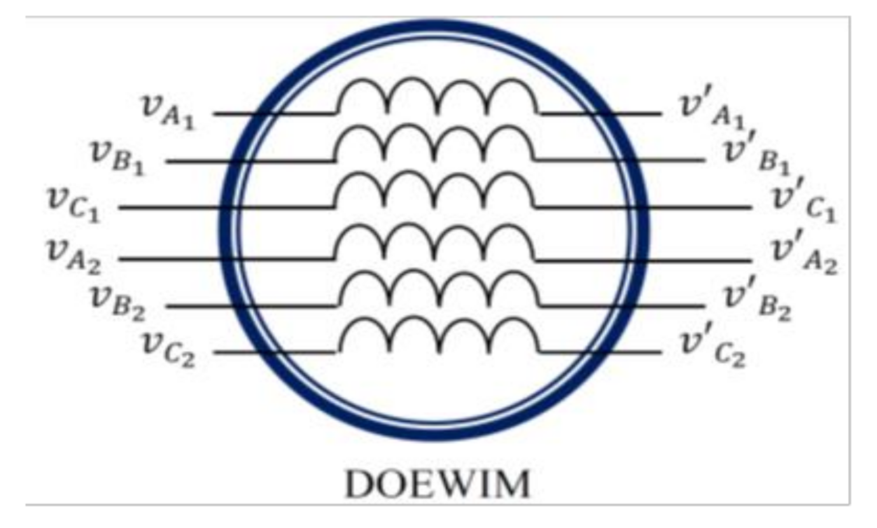
2.1. Dual Open-End Winding Induction Motor Description

The DOEWIM is a DSIM with open stator windings and therefore consists of two open-ended and identical three-phase windings, forming the two stars which share the same stator and are shifted by an electric angle of π / 6 . They have the same number of poles and are fed at the same frequency, with the existence of a shift of 2 π / 3 between the three axes of each winding. The rotor is a squirrel cage rotor with a structure that remains identical to that of a three-phase machine [37]. It is also considered a machine that has twelve terminals at the stator level and needs four three-phase systems to feed it.
Consider that v A 1 ,   v B 1 ,   v C 1 ,   v A 1 ,   v B 1 , and v C 1 correspond, respectively, to the pole voltages at the six outputs of the first converter that are feeding the first ends of the two stator windings, while v A 2 ,   v B 2 ,   v C 2 ,   v A 2 ,   v B 2 , and v C 2 correspond, respectively, to the pole voltages at the six outputs of the second converter that are feeding the second ends of the two previous stator windings, as shown in Figure 1.
The voltage across each phase winding among the six phases of the studied motor can be obtained based on the difference between the corresponding terminal voltages applied to its ends, as follows:
First   stator :   V A 1 = v A 1 v A 1 V B 1 = v B 1 v B 1 V C 1 = v C 1 v C 1
Sec ond   stator :   V A 2 = v A 2 v A 2 V B 1 = v B 2 v B 2 V C 1 = v C 2 v C 2

2.2. Dual Open-End Winding Induction Motor Modeling

The dual open-end winding induction motor with the distribution of its windings and its own geometry is very complex and allows for an analysis, taking into account its exact configuration. However, the model that we will adopt takes into account the following simplifying hypotheses [38,39,40]:
  • The saturation and hysteresis effects of the magnetic circuit are neglected.
  • The effect of the temperature variation on the resistances and inductances of the windings is also neglected.
  • The air gap thickness is uniform and the notching effect is negligible.
  • The magnetomotive force has a sinusoidal spatial distribution.
  • The machine has a symmetrical construction.
  • The two stator windings are balanced and identical.
  • The mutual leakage inductance common to the two windings is negligible.
Based on these assumptions, the DOEWIM model in the α , β frame can be presented as follows.
  • The stator and rotor voltages equations:
V s α 1 = R s 1 i s α 1 + d φ s α 1 d t V s β 1 = R s 1 i s β 1 + d φ s β 1 d t V s α 2 = R s 2 i s α 2 + d φ s α 2 d t V s β 2 = R s 2 i s β 2 + d φ s β 2 d t V r α = R r i r α + d φ r α d t + ω r φ r β = 0 V r β = R r i r β + d φ r β d t + ω r φ r α = 0
with
V s α 1 = v s α 1 v s α 1 V s β 1 = v s β 1 v s β 1 V s α 2 = v s α 2 v s α 2 V s β 2 = v s β 2 v s β 2
  • The stator and rotor flux equations:
φ s α 1 = L s 1 i s α 1 + L m i s α 1 + i s α 2 + i r α φ s β 1 = L s 1 i s β 1 + L m i s β 1 + i   s β 2 + i r β φ s α 2 = L s 2 i s α 2 + L m ( i s α 1 + i s α 2 + i r α ) φ s β 2 = L s 2 i s β 2 + L m ( i s β 1 + i   s β 2 + i r β ) φ r α = L r i r α + L m ( i s α 1 + i s α 2 + i r α ) φ r β = L r i r β + L m ( i s β 1 + i   s β 2 + i r β )
  • The mechanical equation:
J P d ω r d t = T e m T L K f P ω r

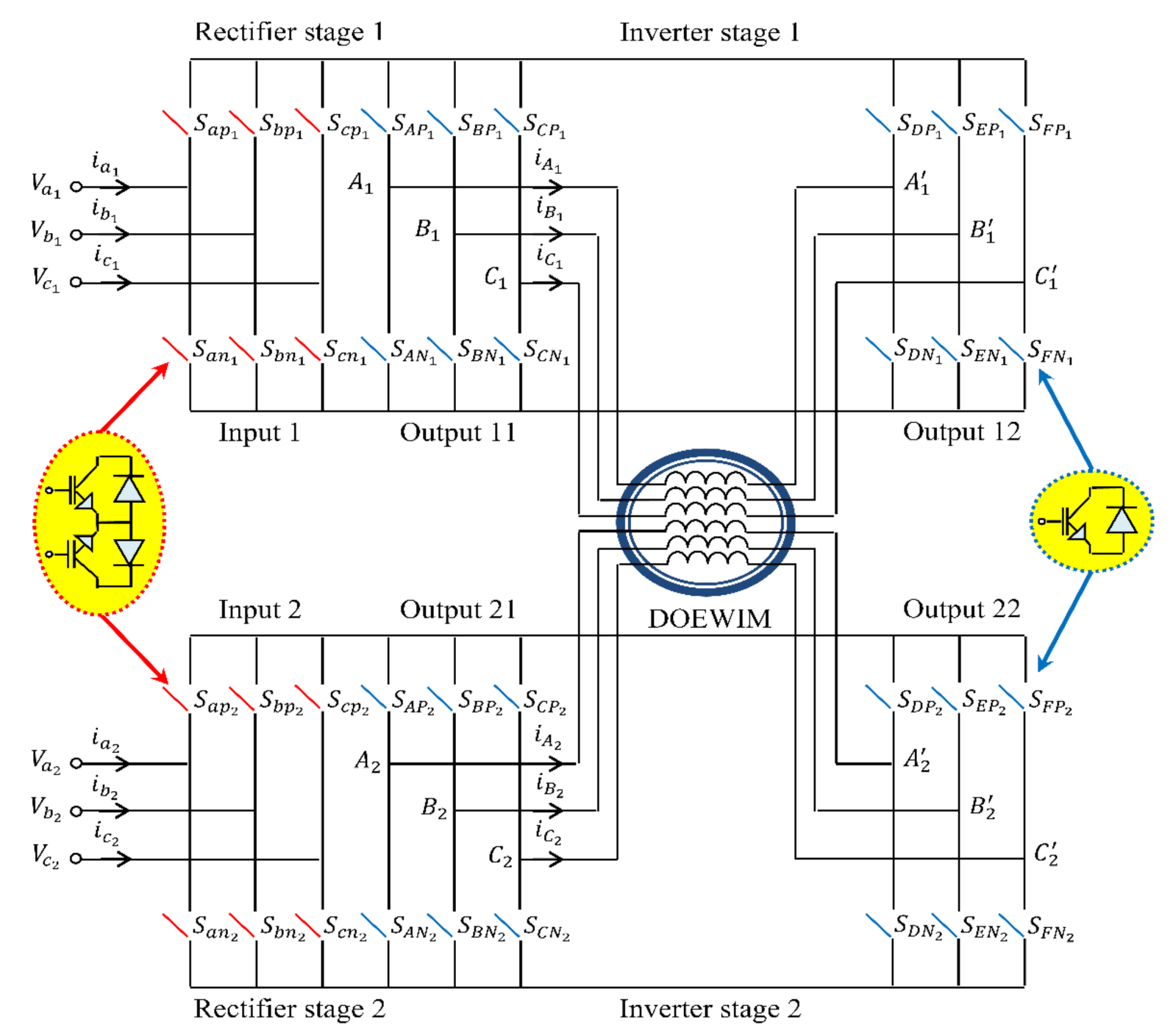
3. Indirect Matrix Converter

3.1. Dual-Outputs Indirect Matrix Converter Topology

The conventional indirect matrix converter structure consists of two stages. The first is the rectifier stage, formed by six bidirectional switches and each is composed of the modules of power electronic switches as shown in Figure 2; it offers the operating possibility in four quadrants including the direct matrix converter. The second stage is similar to a conventional voltage inverter. Thus, this indirect matrix converter can be considered as a combination between a four-quadrant current rectifier and a two-level voltage inverter connected by a virtual DC link [22].
However, to ensure the power supply of the studied motor with the open-end configuration, a new IMC topology is proposed. It consists of an input stage and two output stages, which allow ensuring a three-phase voltage supply at both outputs. This new structure is obtained by both maintaining the input stage as in the conventional structure and making the output stage consist of two independent voltage inverters, which are connected to the same DC link voltage [23,24,41]. This topology will be used in this paper to power the studied DOEWIM drive from both sides of the six phases’ windings independently, in which the motor stator is fed by four three-phase voltages systems, as shown in Figure 2.
Based on the model of the two-output indirect matrix converter, the conversion matrix for each converter is defined as the product of two conversion matrices on each side (inverter and rectifier).
  • First, we discuss the modelling of the first IMC.
Given that v A 1 = v A 1 ,   v B 1 = v B 1 and v C 1 = v C 1 , the following equations are obtained accordingly:
v A 1 v B 1 v C 1 = S A P 1   S B P 1 S C P 1 S A N 1 S B N 1 S C N 1 S a p 1 S a n 1 S b p 1 S b n 1 S c p 1 S c n 1 V a 1 V b 1 V c 1 = C V i n v 11 C V r e c 1 V i 1
v A 1 v B 1 v C 1 = S A a 1   S B a 1 S C a 1 S A b 1 S B b 1 S C b 1 S A c 1 S B c 1 S C c 1 V i 1
v A 1 v B 1 v C 1 = S D P 1   S E P 1 S F P 1 S D N 1 S E N 1 S F N 1 S a p 1 S a n 1 S b p 1 S b n 1 S c p 1 S c n 1 V a 1 V b 1 V c 1 = C V i n v 12 C V r e c 1 V i 1
v A 1 v B 1 v C 1 = S D a 1   S E a 1 S F a 1 S D b 1 S E b 1 S F b 1 S D c 1 S E c 1 S F c 1 V i 1
  • Second, we discuss the modelling of the second IMC.
Given that v A 2 = v A 2 ,   v B 2 = v B 2 and v C 2 = v C 2 , the following equations are obtained accordingly:
v A 2 v B 2 v C 2 = S A P 2   S B P 2 S C P 2 S A N 2 S B N 2 S C N 2 S a p 2 S a n 2 S b p 2 S b n 2 S c p 2 S c n 2 V a 2 V b 2 V c 2 = C V i n v 21 C V r e c 2 V i 2
v A 2 v B 2 v C 2 = S A a 2   S B a 2 S C a 2 S A b 2 S B b 2 S C b 2 S A c 2 S B c 2 S C c 2 V i 2
v A 2 v B 2 v C 2 = S D P 2   S E P 2 S F P 2 S D N 2 S E N 2 S F N 2 S a p 2 S a n 2 S b p 2 S b n 2 S c p 2 S c n 2 V a 2 V b 2 V c 2 = C V i n v 22 C V r e c 2 V i 2
v A 2 v B 2 v C 2 = S D a 2   S E a 2 S F a 2 S D b 2 S E b 2 S F b 2 S D c 2 S E c 2 S F c 2 V i 2
where S j k   is the connection function defined as follows:
S j k = 1     S j k   s w i t h   o n 0     S j k   s w i t h   o f f
V i 1   and   V i 2 are the input voltages.

3.2. Space Vector Modulation for Dual-Outputs Indirect Matrix Converter

The basic idea of the space vector modulation technique for each IMC is to dissociate the input current’s control from the output voltage’s control based on Equations (6), (8),(10) and (12). The SVM is applied in synchronization for each stage using two active vectors and a zero vector to synthesize the three reference vectors, namely V o 1 ,   V o 2 (the two output voltages for the inverter stage), and I i   (the input current for the rectifier stage) for each IMC. This synchronization is essential in order to have the desired output voltages and minimize the low frequency harmonics [42].

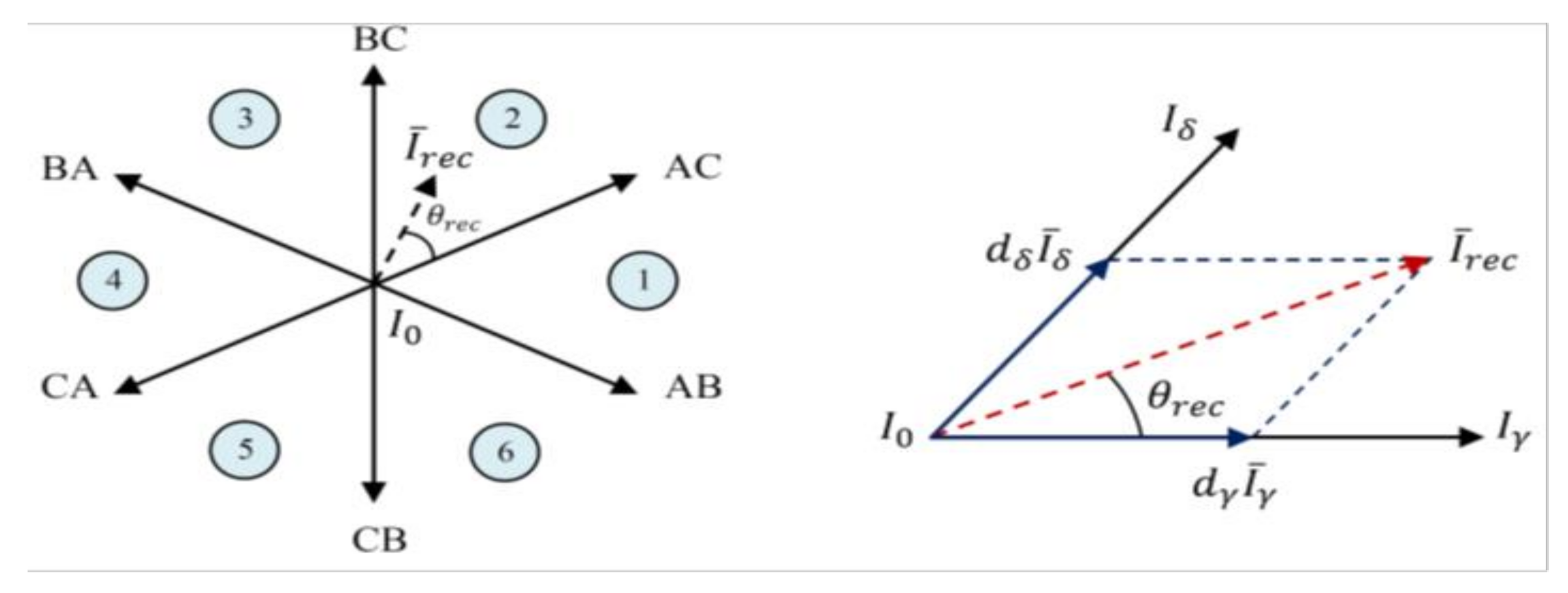
3.2.1. Rectifier Stage Control

As long as the current I r e c is considered practically as a constant value during the switching period T s and to ensure the respect of the rules which is essential for the rectifier stage, the following equations have to be satisfied:
First   IMC :   S a p 1 + S b p 1 + S c p 1 = 1 S a n 1 + S b n 1 + S c n 1 = 1
Sec ond   IMC :   S a p 2 + S b p 2 + S c p 2 = 1 S a n 2 + S b n 2 + S c n 2 = 1
The SVM of the rectifier stage depends on the synthesis of reference current vector I i from two active adjacent vectors and a zero vector, for which their duty cycles are given by the following equation:
d γ = m r e c sin θ r e c d δ = m r e c sin π 3 θ r e c d 0 = 1 d γ d δ
where m r e c = I i I r e c .
The determination of input current vector I i is based on the principle of the modulation algorithm in the δ ,   γ plane, which divides this plane into six sectors delimited by the active vectors, as shown in Figure 3.

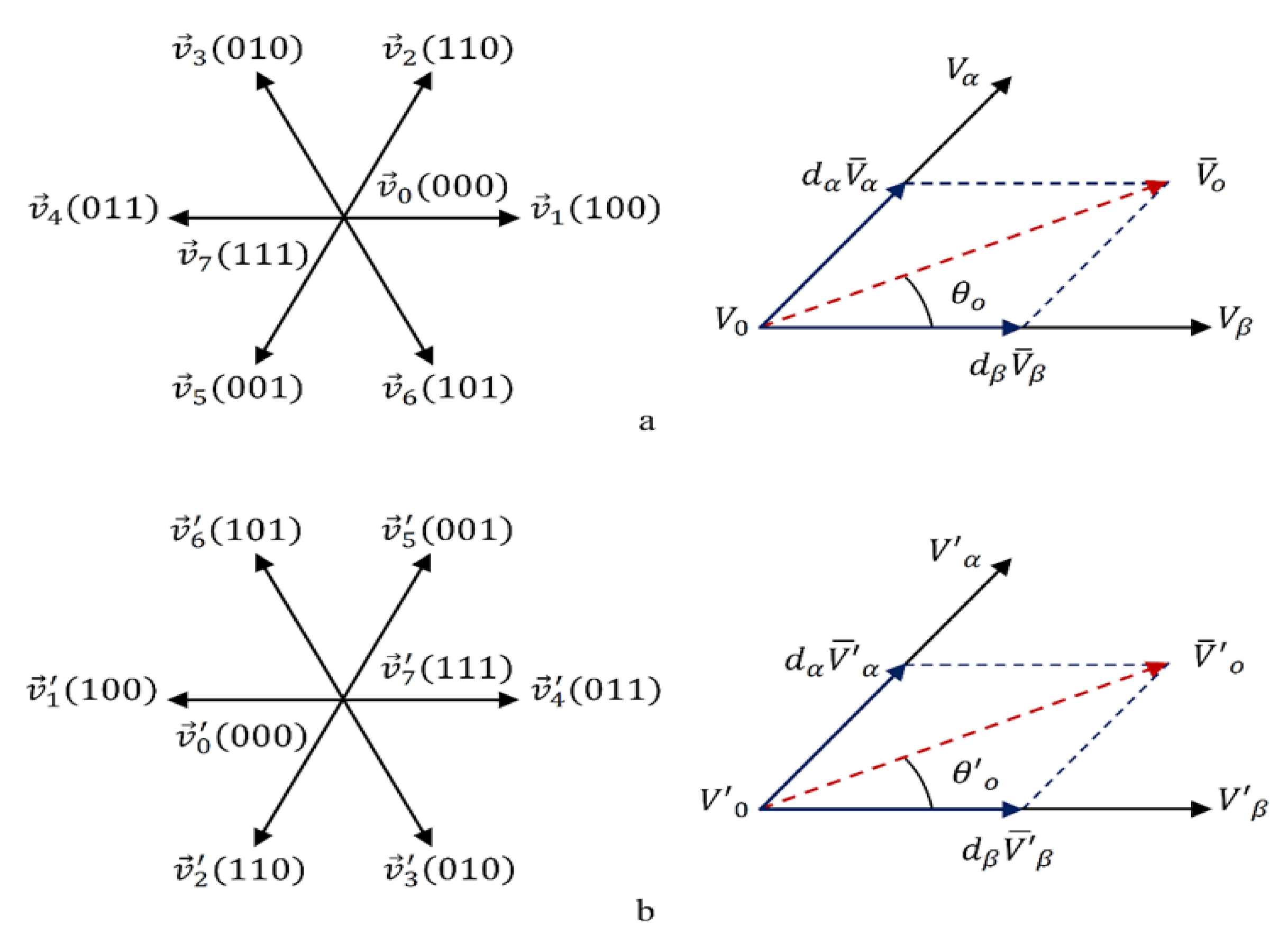
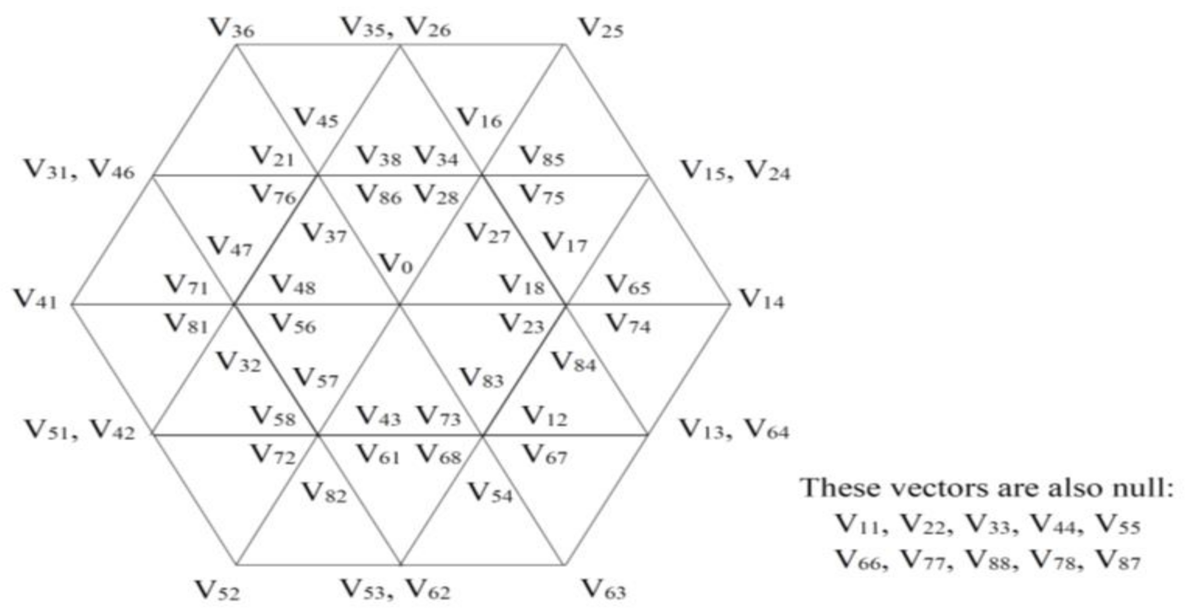
3.2.2. Inverter Stage Control

As in the rectification stage, it is considered that the virtual voltage U v is constant during the switching period T s . To avoid the DC bus short circuit, only one switch per arm must be on in each IMC, which requires that the following equations have to be fulfilled:
First   IMC :   S j P 1 + S j N 1 = 1
Sec ond   IMC :   S j P 2 + S j N 2 = 1
where S j P 1 ,   S j N 1 and S j P 2 ,   S j N 2   are the single arm connection functions for the two indirect matrix converters 1 and 2, respectively.
The plane α ,   β is divided into six sectors delimited by the active vectors. According to the principle of SVM, the output voltage vector V 0 for each output of each IMC can be synthesized using the two adjacent vectors V α   and   V β , and the zero vector V 0 , as shown in Figure 4.
The duty cycles of the two outputs’ voltage vectors for the first IMC are defined, respectively, as follows:
First   output :   d α = m i n v sin π 3 θ o d β = m i n v sin θ o d V 0 = 1 d γ d δ
Second   output :   d α = m i n v sin π 3 θ o d β = m i n v sin θ o d V o = 1 d γ d δ
where m i n v   and   m i n v are the two outputs’ voltage rations of the inverters of the first stage, respectively, which are defined as follows:
m i n v = 3 V o 1 U v
Considering the two-level inverter produces eight commutation states, the new configuration of the IMC is based on the combination of two two-level inverters in its output, which allows for generating sixty-four (8 * 8) commutation states. Figure 5 shows the resulting commutation states from their combination. It is important to note that the same principle is applied for both stator windings of the studied DOEWIM.
The voltage space vectors for each dual-inverter, which constitute the four outputs of the two IMCs, are defined as follows:
First   stator :   v 1 = 2 6 v A 1 + v B 1 e j 2 π 3 + v C 1 e j 4 π 3 = v 1 e j α 1 v 1 = 2 6 v A 1 + v B 1 e j 2 π 3 + v C 1 e j 4 π 3 = v 1 e j α 1
Sec ond   stator :   v 2 = 2 6 v A 2 e j π 6 + v B 2 e j 5 π 6 + v C 2 e j 9 π 6 = v 2 e j α 2 v 2 = 2 6 v A 2 e j π 6 + v B 2 e j 5 π 6 + v C 2 e j 7 π 6 = v 2 e j α 2
From the combination of the two inverters, which are feeding each of the two stator windings, the resulting voltage vectors at the terminals can be synthesized as follows:
First   stator :   v 1 + v 1 = V 0 1 = 2 6 V A 1 + V B 1 e j 2 π 3 + V C 1 e j 4 π 3 = V 0 1 e j α 0 1
Second   stator :   v 2 + v 2 = V 0 2 = 2 6 V A 2 e j π 6 + V B 2 e j 5 π 6 + V C 2 e j 9 π 6 = V 0 2 e j α 0 2
where V A 1 , V B 1 ,   V C 1 ,   V A 2 ,   V B 2 , and V C 2 are the voltages at the terminals of each phase of stator winding 1 and 2.

3.3. Common Mode Voltage

It is obvious that the conventional IMC topology is defective in the generation of common-mode voltages in the induction motor, allowing for leakage current to pass through the stator windings, which reduces the life duration of the isolations protecting them, causing frequent breakdowns of these motors. However, the new IMC topology is seen as a preferred solution for eliminating common-mode voltages and its associated problems [43,44].
The common-mode voltage at each end of both stator windings are defined as follows:
First   stator :   v c m 1 = v A 1 + v B 1 + v C 1 3 v c m 1 = v A 1 + v B 1 + v C 1 3
Sec ond   stator :   v c m 2 = v A 2 + v B 2 + v C 2 3 v c m 2 = v A 2 + v B 2 + v C 2 3
where
  • v c m 1 is the common-mode voltage at the first end of the first stator;
  • v c m 1 is the common-mode voltage at the second end of the first stator;
  • v c m 2 is the common-mode voltage at the first end of the second stator; and
  • v c m 2 is the common-mode voltage at the second end of the second stator.
The common mode voltages, which pass through the phases of each of the two stators, are simply defined as the differences in the common-mode voltages between the two ends of each stator. They are given as follows:
First   stator :   V C M 1 = v c m 1 v c m 1
Sec ond   stator :   V C M 2 = v c m 2 v c m 2

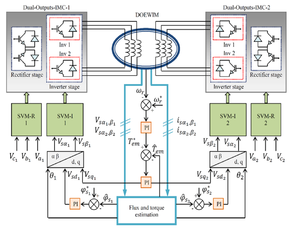
4. Direct Torque Control Technique

Indeed, the DTC technique was initially proposed for inverters [45] and then it was adapted to matrix converters [46]. Its strategy is based on the direct control of the amplitude and rotation speed of the stator flux using two hysteresis controllers and a commutation table to directly generate the controlled converter output voltage, for which the hysteresis regulators allowed us to place the electromagnetic torque and stator flux in a very precise hysteresis band. It is obvious that the traditional DTC has several drawbacks, the most important of which are the variable switching frequency and torque oscillations caused by the hysteresis controllers.
Under these conditions and in order to overcome the problems of the conventional DTC, the space vector modulator was introduced in its structure, which yields to the technique known as DTC-SVM. This technique has the SVM advantages, such as the constant switching frequency, low current THD, high dynamics, etc., while retaining the DTC characteristics, such as simple and robust structure, lack of internal current regulation loop, etc. [26].
Instead of hysteresis comparators and the commutation table, two PI controllers are introduced into the internal control loop, in which the torque and stator flux references are compared with their actual values in order to derive the errors, which will be used thereafter as inputs to the PI controllers. The outputs of these controllers are transformed to new frame coordinates by the vector modulation block, wherein the main aim is to generate reference voltages and hence provide a better commutation state of the IMC switches [47].

Stator Flux and Electromagnetic Torque Estimation

Basically, the accurate stator flux knowledge is very important in the DTC-SVM technique. Indeed, a simple and effective method is used to calculate the stator flux from the voltage, current, and stator resistance independently of the other machine parameters. This can be presented as follows:
First   stator :   φ s α 1 = V s α 1 i s α 1 R s 1 d t φ s β 1 = V s β 1 i s β 1 R s 1 d t
Sec ond   stator :   φ s α 2 = V s α 2 i s α 2 R s 2 d t φ s β 2 = V s β 2 i s β 2 R s 2 d t
In a high frequency, the effect of the error in R s generally becomes quite negligible, unlike cases with a frequency close to zero, for which the effect of this error is very important.
Based on the previous equations, the magnitude and angle of the estimated stator flux phasor of both windings can be obtained as follows:
First   stator :   φ s 1 = φ s α 1 2 + φ s β 1 2 θ 1 = a r c t g φ s β 1 φ s α 1
Sec ond   stator :   φ s 2 = φ s α 2 2 + φ s β 2 2 θ 2 = a r c t g φ s β 2 φ s α 2
The estimated electromagnetic torque can be obtained based on the estimated stator fluxes and measured stator currents as follows:
T e m = P φ s α 1 i s β 1 + φ s α 2 i s β 2 φ s β 1 i s α 1 φ s β 2 i s α 2
Figure 6 provides the general diagram of the direct torque control structure of a DOEWM supplied by two dual-outputs indirect matrix converters, it comprisr also the stator flux controller and the electromagnetic torque controller. This control technique is combined with the SVM for the purpose of achieving high performance.

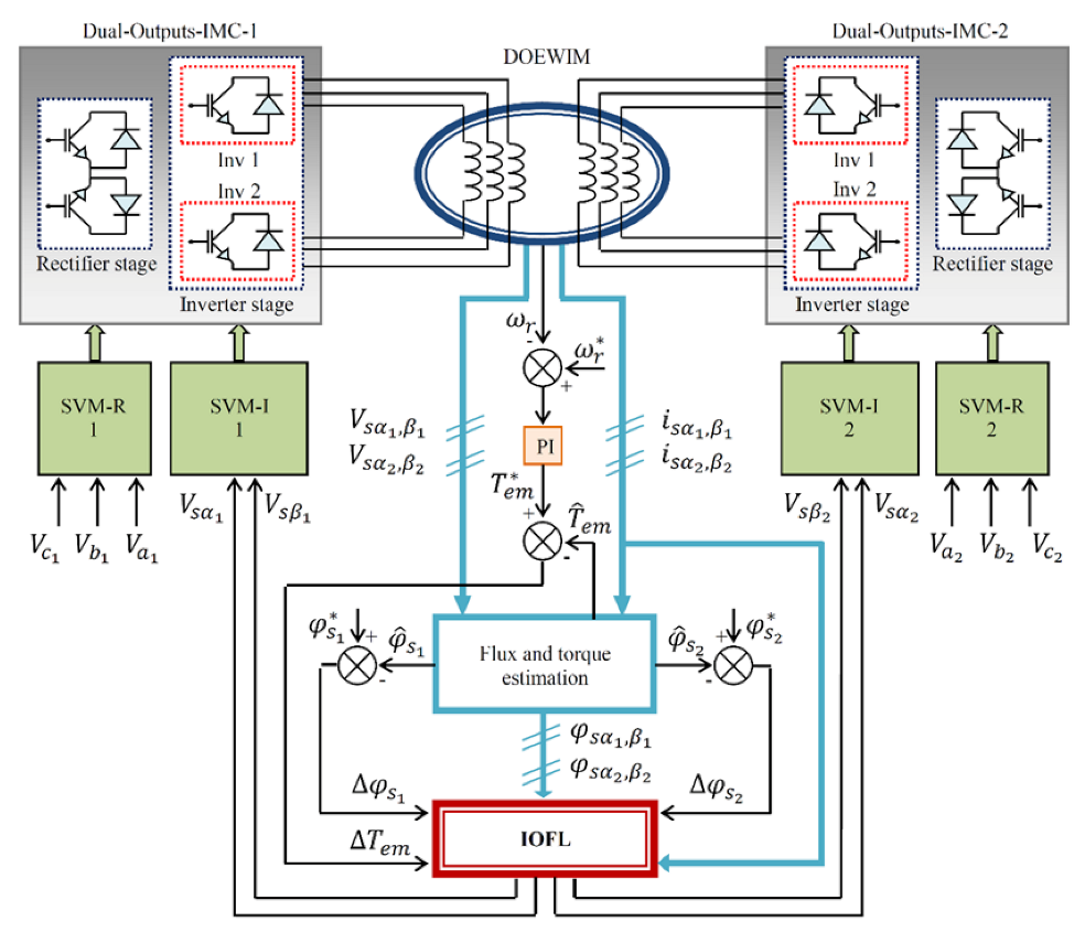
5. Input–Output Feedback Linearization

To further improve DTC-SVM by reducing more and more of the oscillations at the torque and stator flux levels, and in order to simplify the control algorithm complexity by completely eliminating Concordia transformation, the input–output feedback linearization guarantees these improvements and simplifications with the provision of a perfect decoupling of the torque and stator flux [32].
The DOEWIM model that has been relied upon in applying the IOFL technique is written as follows.
  • Dynamic equations:
d i s α 1 d t = a 1 i s α 1 + a 2 i s α 2 + a 8 φ r α + ( p . a 9 . ω r ) φ r β + b 1 V s α 1 b 2 V s α 2 d i s β 1 d t = a 1 i s β 1 + a 2 i s β 2 ( p . a 9 . ω r ) φ r α + a 8 φ r β + b 1 V s β 1 b 2 V s β 2 d i s α 2 d t = a 2 i s α 1 + a 1 i s α 2 + a 8 φ r α + ( p . a 9 . ω r ) φ r β b 2 V s α 1 + b 1 V s α 2 d i s β 2 d t = a 2 i s β 1 + a 1 i s β 2 p . a 9 . ω r φ r α + a 8 φ r β b 2 V s β 1 b 1 V s β 2 d φ s α 1 d t = V s α 1 R s 1 i s α 1 d φ s β 1 d t = V s β 1 R s 1 i s β 1 d φ s α 2 d t = V s α 2 R s 2 i s α 2 d φ s β 2 d t = V s β 2 R s 2 i s β 2
with
a 1 = L s 1 + L m L m 2 L m + L r ;   a 2 = L m L m 2 L m + L r ;   a 3 = L m L m + L r ;   a 4 = R r L m L m + L r ;   a 5 = R r L m + L r ;   a 6 = a 1 R s 1 a 1 2 a 2 2 + a 3 a 4 a 1 + a 2 ;   a 7 = a 2 R s 2 a 1 2 a 2 2 a 3 a 4 a 1 + a 2 ;   a 8 = a 3 a 5 a 1 + a 2 ;   a 9 = a 3 a 1 + a 2 ;   b 1 = a 1 a 1 2 a 2 2 ;   b 2 = a 2 a 1 2 a 2 2 ;
  • The electromagnetic torque expression is the same as was given in Equation (36).
The system of equations is written in the form suggested for the application of linearization in the sense of input–output as follows:
x ˙ = f x + G 1 x + G 2 x
y = h x
where the expressions
( x ) = a 1 i s α 1 + a 2 i s α 2 + a 8 φ r α + ( p . a 9 . ω r ) φ r β a 1 i s β 1 + a 2 i s β 2 ( p . a 9 . ω r ) φ r α + a 8 φ r β a 2 i s α 1 + a 1 i s α 2 + a 8 φ r α + ( p . a 9 . ω r ) φ r β a 2 i s β 1 + a 1 i s β 2 ( p . a 9 . ω r ) φ r α + a 8 φ r β R s 1 i s α 1 R s 1 i s β 1 R s 2 i s α 2 R s 2 i s β 2
G 1 x = g 1 x · V s α 1 + g 2 x · V s α 2 + g 3 x · V s β 1 + g 4 x · V s β 2
G 2 x = g 5 x · V s α 1 + g 6 x · V s α 2 + g 7 x · V s β 1 + g 8 x · V s β 2
The matrix forms for g 1 x , g 2 x , g 3 x , g 4 x , g 5 x , g 6 x , g 7 x , and g 8 x are represented, respectively, as follows:
g 1 x = b 1 0 0 0 1 0 0 0 T
g 2 x = b 2 0 0 0 0 0 0 0 T
g 3 x = 0 b 2 0 0 0 1 0 0 T
g 4 x = 0 b 1 0 0 0 0 0 0 T
g 5 x = 0 0 b 1 0 0 0 0 0 T
g 6 x = 0 0 b 2 0 0 0 1 0 T
g 7 x = 0 0 0 b 2 0 0 0 0 T
g 8 x = 0 0 0 b 1 0 0 0 1 T
The expression of x is also defined as follows:
  X = i s α 1 i s β 1 i s α 2 i s β 2 φ s α 1 φ s β 1 φ s α 2 φ s β 2 T
The system outputs are represented by the torque produced by the motor and the stator flux squared modules, and they are expressed as follows:
h 1 x = T e m = P φ s α 1 i s β 1 + φ s α 2 i s β 2 φ s β 1 i s α 1 φ s β 2 i s α 2
h 2 x = φ s 1 2 = φ s α 1 2 + φ s β 1 2
h 3 x = φ s 2 2 = φ s α 2 2 + φ s β 2 2

5.1. IOFL Technique

To simplify the linearization of our non-linear system, the Lie derivative is introduced to guarantee the differentiation of the controlled variable with respect to time until the input appears [34].
The degree relating to the torque is defined as follows.
  • First stator:
y ˙ 1 = L f h 1 x + L g 1 h 1 x V s α 1 + L g 2 h 1 x V s α 2 + L g 3 h 1 x V s β 1 + L g 4 h 1 x V s β 2
  • Second stator:
y ˙ 2 = L f h 1 x + L g 5 h 1 x V s α 1 + L g 6 h 1 x V s α 2 + L g 7 h 1 x V s β 1 + L g 8 h 1 x V s β 2
The two relations that give the two-stator flux are as follows.
  • First stator:
y ˙ 3 = L f h 2 x + L g 1 h 2 x V s α 1 + L g 2 h 2 x V s α 2 + L g 3 h 2 x V s β 1 + L g 4 h 2 x V s β 2
  • Second stator:
y ˙ 4 = L f h 3 x + L g 5 h 3 x V s α 1 + L g 6 h 3 x V s α 2 + L g 7 h 3 x V s β 1 + L g 8 h 3 x V s β 2

5.2. Non-Linear Control Law

The non-linear control law defines the relation that connects the physical input u   x to the output derivative y x in the form of a matrix given by the following formula [32]:
y ˙ 1 y ˙ 2 y ˙ 3 y ˙ 4 T = A x + E x V s α 1 V s α 2 V s β 1 V s β 2 T
with
A x = L f h 1 L f h 1 L f h 2 L f h 3 T E x = L g 1 h 1 L g 2 h 1 L g 3 h 1 L g 4 h 1 L g 5 h 1 L g 6 h 1 L g 7 h 1 L g 8 h 1 2 φ s α 1 0 2 φ s β 1 0 0 2 φ s α 1 0 2 φ s β 1
The expression that provides the SVM block inputs is as follows:
V 1 = φ ˙ s 1 r e f 2 + k 1 φ s 1 r e f 2 φ s 1 2 V 1 = V 4 = T ˙ e m r e f + k 2 T ˙ e m r e f T e m V 3 = φ ˙ s 2 r e f 2 + k 3 φ s 2 r e f 2 φ s 2 2
with k 1 , k 3 , and k 2 assumed as positive gains and generally k 1 = k 3 .
The IOFL-DTC-SVM performances are directly affected by the selection of these gains because the system is distinguished by its slow convergence and weakness of robustness when small values are given to the gains, and this presents a strong perturbation and instability when receiving these gains’ large values. Contrary to all this, though, the choice of appropriate values leads to perfect and excellent regulation.
Figure 7 represents the block diagram of a direct torque control associated with a non-linear control based on input–output feedback linearization, with SVM applied to a DOEWIM supplied by two dual-outputs indirect matrix converters.

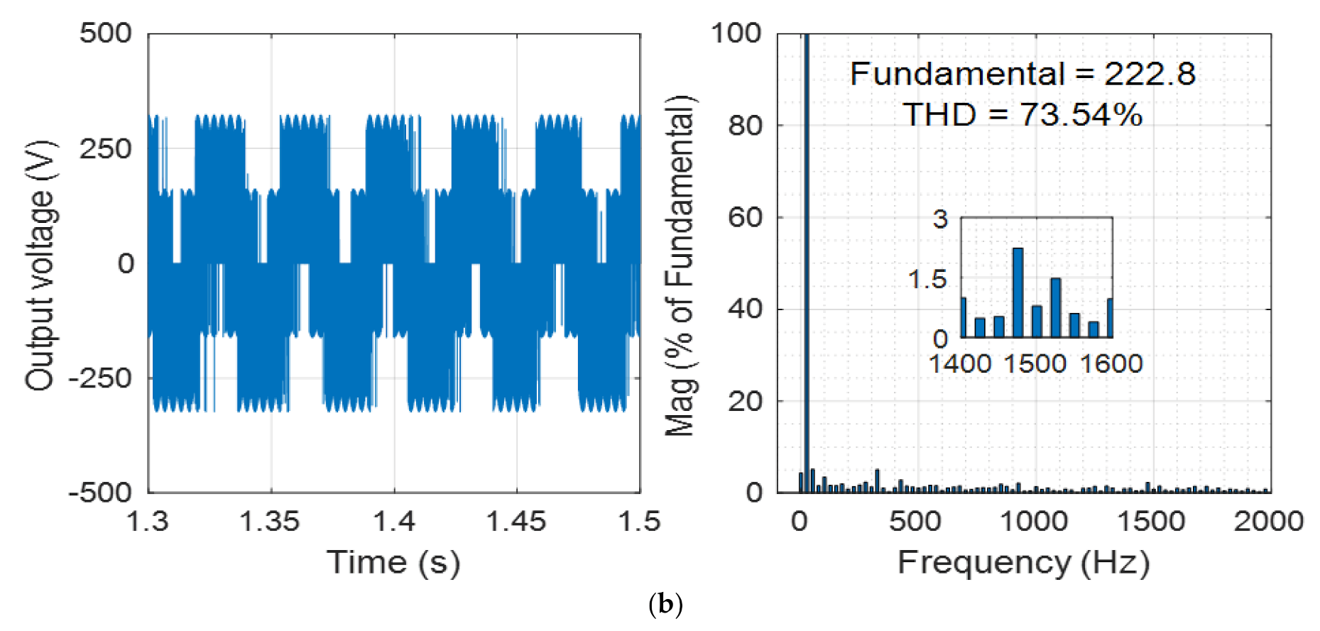
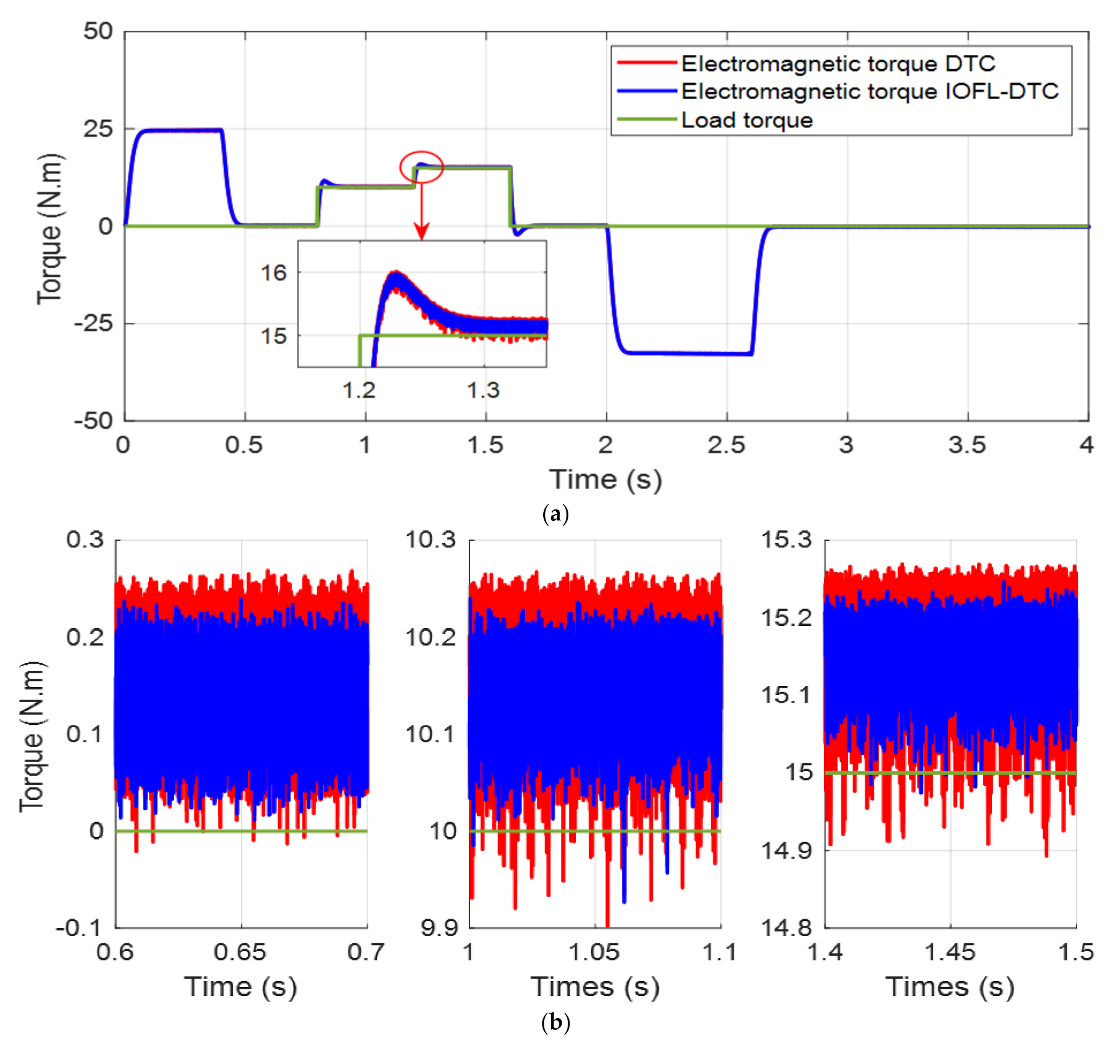
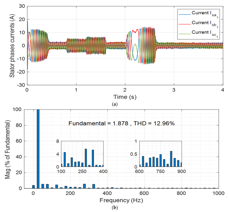
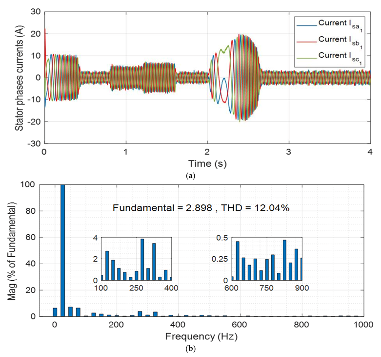
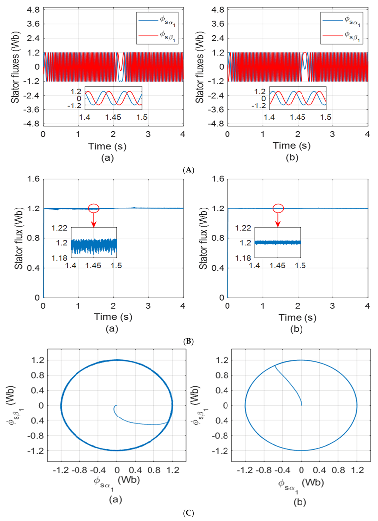
6. Simulation Results and Discussion

In this section, the application of the conventional DTC-SVM and IOFL-DTC-SVM for the control of the DOEWIM were carried out under simulation tests. The main characteristics of the machine under study are presented in the Appendix.
The main objective is to present a detailed comparison between the performances of both techniques based on the analysis of the dynamic behavior of the chosen electrical, electromagnetic, and mechanical control variables, such as the stator current, electromagnetic torque, stator flux, and rotor speed. For this purpose, simulation tests have been performed for both techniques under similar operating conditions and identical controller parameters. In addition, the tests were carried out for a reference speed that is equal to 50 %   157   rad / s of the motor rated speed, taking into account the steps of starting-up under no load, load torque application, and speed reverse.
Indeed, these simulations included a sequence of steps that could imitate the practical cases in industrial applications. The machine started up at t = 0   s with no load following an imposed reference speed profile; at t = 0.8   s with a load torque of T L = 10   N · m applied, which is considered as an external perturbation; at t = 1.2   s with the applied load torque increased to T L = 15   N · m ; and at t = 1.6   s wherein the applied load torque was removed, which means that T L = 0   N · m . The second part of these simulations present the dynamic behavior of the two proposed control techniques against the speed revers, for which at t = 2   s , the reference speed was the reverse without the application of any load torque.
The voltage waveforms and their harmonics spectrum obtained by the two techniques DTC-SVM and IOFL-DTC-SVM are shown in Figure 8a,b, respectively. It is important to clarify that the range of the spectrum window was limited to 2   kHz in this figure. This choice was made because all the other components are neglected compared to the low frequency components, in addition to the fact that their presentation does not make any sense and their impact on the dynamic behavior of the motor are totally neglected. According to the observation of the harmonic spectrum of the obtained voltages at phase “a” of the first stator winding for the conventional DCT-SVM and IOFL-DTC-SVM, it can be deduced that in the case of the conventional DTC-SVM, the harmonics content was more important with T H D v = 83.71 % in comparison with the case of IOFL-DTC-SVM, which was characterized by T H D v = 73.54 % . It can be said that the obtained voltage quality helped in ensuring less electromagnetic torque ripples for the proposed technique.
Figure 9a presents the dynamic evolution of the motor rotor speeds resulting from both techniques compared to the reference rotor speed. It can be clearly seen that the speed response was the same for the two approaches, wherein the rotor speed tracked the reference speed during along the speed profile with a very small error between the references speed and the developed speed in both cases. It can be clearly noticed that the profile of the reference speed passed from N = 157   rad / s to N = 157   rad / s in a linear manner, which imitates the real practical case, due to the fact that the change of the direction of the rotor speed cannot physically occur in an instantaneous way. From Figure 9a, it can be said that the dynamic evolution of the speed, in comparison with the imposed speed reference, was very satisfactory within all the aforementioned operating steps. Furthermore, it can be observed that the load torque variation did not affect the reference tracking dynamic under the application of both techniques, wherein its effect can be neglected as shown in the depicted zoomed-in graph window presented in Figure 9a between times t = 0.35   s and t = 0.55   s , t = 1.55   s and t = 1.75   s , and t = 2.55   s and t = 2.75   s . Therefore, we can say that the response time and external disturbances’ impact on the rotor speed were the same for both the conventional DTC-SVM and IOFL-DTC-SVM techniques, but in terms of error between the reference speed and the developed speed by the machine, the preference was for IOFL-DTC-SVM as this error was less compared to the conventional DTC-SVM, which makes the machine more stable and less turbulent. This is what the zoomed-in graph window shows between the two instants of t = 1.4   s and t = 1.5   s in Figure 9a, as well as in the speed error zoomed-in graph window shown in Figure 9b.
Figure 10a shows the electromagnetic torque T e m developed by DOEWIM under the application of both techniques. It is obvious that in both cases, the T e m tracked the load torque within a very short time of 0.1   s with a neglected disturbance impact on the quality of the speed, as shown in Figure 9a and 9b. In addition, the overshoots of the developed T e m in both cases for different loads were small within the range of 1 N.m. It is important to clarify that the DOEWIM benefits naturally from the main features of multiphase machines, where the torque ripple is considerably reduced in comparison to their three-phase machine counterpart, and the first harmonics component contained in the torque is of the order of twelve times of the fundamental frequency of the voltage applied on the double stator. However, the IOFL-DTC-SVM technique presented a very interesting advantage, wherein the resulting T e m ripple peak values (their magnitudes) were significantly reduced in comparison to the conventional DTC-SVM technique, as it can be clearly noticed in Figure 10b. This advantage allowed for reducing the mechanical stresses along the shaft and bearings, obtaining less noise and vibrations in the machine, and thus better efficiency can be achieved. In fact, this is due to the quality of the voltage applied to the stator winding when using IOFL-DTC-SVM compared to the case of the conventional DTC-SVM. The non-exact congruence of the load torque and the average value of the developed T e m were due to the difference produced by the relating friction torque, which depends essentially on the motor rotor speed and the friction coefficient, as presented in Table A1. In the present case, the friction torque was K f · ω r = 0.157   N · m .
The currents in the three phases of the first stator winding for the two techniques are shown, respectively, in Figure 11a and Figure 12a, along the aforementioned simulation steps. It can be observed that the start-up peak current for the proposed technique had a lower value than the conventional technique, while the time for this transition was nearly the same for both techniques. Also the two figures show that the application of the load torque generated progressive increases in the phase currents, proportional directly to the value of the load torque in a similar way for the two techniques; this is also noted during the transition phase when the speed was reversed, characterized by an increase in the magnitudes of the phase currents, which were higher in the case of IOFL-DTC-SVM compared to the DTC-SVM. Figure 11b and Figure 12b show the harmonic spectrum of the phase current of phase “a” of the first stator winding for both strategies. It is important to clarify that the range of the spectrum window was limited to 1   kHz in these figures. This choice was made due to the fact that all the other components are neglected compared to the low frequency components, in addition to the fact that their presentation does not make any sense and their impact on the dynamic behavior of the motor are totally neglected. It is obvious that in the case of the IOFL-DCT-SVM, the harmonics content was less important, with T H D i = 12.04 % , in comparison to the case of DTC-SVM, which was characterized by T H D i = 12.96 % ; this led to less ripples in the electromagnetic torque. Indeed, this feature can be considered as one among the other advantages of using the proposed strategy compared to the conventional strategy that may lead to the improvement of the overall performance of the system based on the IOFL.
Figure 13A shows the stator fluxes for the DTC-SVM and IOFL-DTC-SVM techniques following the α ,   β axis, at which it can be observed that very satisfactory dynamic responses were achieved during all the operating steps, during which the two-stator flux components following the α ,   β axis were characterized by a perfect sinusoidal waveform.
Figure 13B shows the resultant stator flux along the simulation steps under the application of both techniques. Indeed, the two obtained resultant fluxes were nearly constant and were not affected by the transient steps, the load changes, nor the rotor speed reversion; this can be explained by the accurate control of DTC, which offered a natural decoupling between the flux and torque. However, the introduction of the IOFL in combination with DTC-SVM allowed for achieving a significant and clear improvement in the rejection of disturbance, which makes the flux smooth, with neglected oscillations, as shown in the depicted zoomed-in-graph window of Figure 13B.
Figure 13C shows the stator flux in the   α , β frame, in which it can be noticed that the application of both techniques ensured a perfectly circular trajectory. This confirms that the flux vector amplitude is kept constant during all operation stages and without overshoot at the start-up. Nevertheless, the proposed technique offers a finer and smoother trajectory than the conventional technique, as shown in Figure 13c.

7. Conclusions

The work presented in this article proves that the matrix converter is a competitive alternative for AC/AC conversion in many industrial applications due to its various advantages compared to other options, particularly in the driving of multiphase machines. The obtained simulation results in this paper show that the application of the DTC-SVM on the DOEWIM provides better control flexibility by guaranteeing the operation with a fixed-switching frequency, neglected overshoot, fast response, and capability to deal with torque and flux disturbances. In the meantime, this technique presents significant ripples in the developed electromagnetic torque, which may lead to more noise and mechanical stress in the machine. However, the insertion of the IOFL technique with the conventional DTC-SVM presents a significant reduction of the torque ripples due current harmonics minimization, which leads to a considerable reduction of the noise and mechanical stress in the machine; hence, long lifespan can be ensured. In addition, the application of IOFL-DTC-SVM allows for simplifying the system modeling by eliminating the Concordia transformation. From this study, it can be concluded that the association of the DTC-SVM with a non-linear technique for the control of the asynchronous double-star machine with its new configuration (DOEWIM), powered by two dual-output indirect matrix converters, ensures high dynamic control, better performance, better robustness, and less computation burdens.

Author Contributions

Conceptualization, M.S., A.K. and M.A.; methodology, M.S., A.K. and M.M.-S.; software, M.S., M.M.-S. and M.M.R.; validation, M.S. and A.K.; formal analysis, A.K. and M.A.; investigation, A.K. and M.M.R.; resources, M.S. and A.K.; data curation, M.S. and A.K.; writing—original draft preparation, M.S. and A.K.; writing—review and editing, M.A. and R.K.; visualization, M.S. and A.K.; supervision, A.K. and M.M.R.; project administration, M.A. and R.K.; funding acquisition, M.A. and R.K. All authors have read and agreed to the published version of the manuscript.

Funding

This research received no external funding.

Institutional Review Board Statement

Not Applicable.

Informed Consent Statement

Not Applicable.

Data Availability Statement

Not Applicable.

Conflicts of Interest

The authors declare no conflict of interest.

Abbreviations

The following abbreviations are used in this manuscript:
DOEWIMdual open-end windings induction motor
DSIMdual-stator induction motor
DTCdirect torque control
SVMspace vector modulation
IOFLinput–output feedback linearization
CMVcommon-mode voltage
FOCfield-oriented control
MCmatrix converter
IMCindirect matrix converter
DCdirect current
ACalternating current
THDtotal harmonic distortion

Appendix A

Table A1. The parameters of DOEWIM.
ParameterValueParameterValue
L m : mutual inductance 0.3672   H K f : friction coefficient 0.001   N · m · rad / s 1
L r : rotor inductance 0.006   H P : number of pole pairs 1
L s 1 = L s 2 : stator inductances 0.022   H J : moment of inertia 0.0625   Kg · m 2
R s 1 = R s 2 : stator resistances 3.72   Ω V n : nominal voltage 220   V
R r : rotor resistance 2.12   Ω P n : nominal power 4.5   Kw

References

  1. Kali, Y.; Saad, M.; Doval-Gandoy, J.; Rodas, J. Discrete Terminal Super-Twisting Current Control of a Six-Phase Induction Motor. Energies 2021, 14, 1339. [Google Scholar] [CrossRef]
  2. Kali, Y.; Ayala, M.; Rodas, J.; Saad, M.; Doval-Gandoy, J.; Gregor, R.; Benjelloun, K. Current Control of a Six-Phase Induction Machine Drive Based on Discrete-Time Sliding Mode with Time Delay Estimation. Energies 2019, 12, 170. [Google Scholar] [CrossRef] [Green Version]
  3. Marouani, K.; Baghli, L.; Hadiouche, D.; Kheloui, A.; Rezzoug, A. A New PWM Strategy Based on a 24-Sector Vector Space Decomposition for a Six-Phase VSI-Fed Dual Stator Induction Motor. IEEE Trans. Ind. Electron. 2008, 55, 1910–1920. [Google Scholar] [CrossRef]
  4. Moati, Y.; Kouzi, K. Investigating the Performances of Direct Torque and Flux Control for Dual Stator Induction Motor with Direct and Indirect Matrix Converter. Period. Polytech. Electr. Eng. Comput. Sci. 2019, 64, 97–105. [Google Scholar] [CrossRef]
  5. Khadar, S.; Kouzou, A.; Rezzaoui, M.M.; Hafaifa, A. Sensorless Control Technique of Open-End Winding Five Phase Induction Motor under Partial Stator Winding Short-Circuit. Period. Polytech. Electr. Eng. Comput. Sci. 2019, 64, 2–19. [Google Scholar] [CrossRef] [Green Version]
  6. Rahali, H.; Zeghlache, S.; Benyettou, L.; Benalia, L. Backstepping Sliding Mode Controller Improved with Interval Type-2 Fuzzy Logic Applied to the Dual Star Induction Motor. Int. J. Comput. Intell. Appl. 2019, 18, 1950012. [Google Scholar] [CrossRef]
  7. Nirsha, K.I.; Rajeevan, P.P. A direct torque control scheme for dual inverter fed induction motor drive with a common DC voltage source. In Proceedings of the IECON 2017—43rd Annual Conference of the IEEE Industrial Electronics Society, Beijing, China, 29 October–1 November 2017. [Google Scholar] [CrossRef]
  8. Ranjit, M.; Gowtami, S.; Babu, B.G. Reduction of zero sequence voltage using multilevel inverter fed open-end winding induction motor drive. Acta Electrotech. Inform. 2016, 16, 52–60. [Google Scholar] [CrossRef]
  9. Foti, S.; Testa, A.; De Caro, S.; Scimone, T.; Scelba, G.; Scarcella, G. Multi-level open end windings multi-motor drives. Energies 2019, 12, 861. [Google Scholar] [CrossRef] [Green Version]
  10. Reddy, B.V.; Somasekhar, V.T. A Dual Inverter Fed Four-Level Open-End Winding Induction Motor Drive With a Nested Rectifier-Inverter. IEEE Trans. Ind. Inform. 2012, 9, 938–946. [Google Scholar] [CrossRef]
  11. Nirsha, K.I.; Rajeevan, P.P. Parameter sensitivity analysis of DTC scheme for dual inverter fed open-end winding IM drive with single DC source. In Proceedings of the 2017 IEEE International WIE Conference on Electrical and Computer Engineering (WIECON-ECE), Dehradun, India, 18–19 December 2017. [Google Scholar] [CrossRef]
  12. Prasad, S.V.S.; Singh, R.R.; Somasekhar, V.T.; Lakhimsetty, S. Performance evaluation of an induction motor drive with direct torque control for open-end winding and cascaded three-level topologies. In Proceedings of the 2017 6th International Conference on Computer Applications in Electrical Engineering-Recent Advances (CERA), Roorkee, India, 5–7 October 2017. [Google Scholar] [CrossRef]
  13. Kumar, K.V.P.; Kumar, T.V. Improvised direct torque control strategies of open end winding PMSM fed with multi-level inversion. In Proceedings of the 2018 IEEE International Conference on Industrial Technology (ICIT), Lyon, France, 20–22 February 2018. [Google Scholar] [CrossRef]
  14. Ranjit, M.; Reddy, T.B.; Suryakalavathi, M. Performance Improvements in Open End Winding Induction Motor Drive Using Decoupled PWM Techniques. Energy Procedia 2017, 117, 810–817. [Google Scholar] [CrossRef]
  15. Saad, K.; Abdellah, K.; Ahmed, H.; Iqbal, A. Investigation on SVM-Backstepping sensorless control of five-phase open-end winding induction motor based on model reference adaptive system and parameter estimation. Eng. Sci. Technol. Int. J. 2019, 22, 1013–1026. [Google Scholar] [CrossRef]
  16. Ansari, S.; Chandel, A. Simulation based comprehensive analysis of direct and indirect matrix converter fed asynchronous motor drive. In Proceedings of the 2017 4th IEEE Uttar Pradesh Section International Conference on Electrical, Computer and Electronics (UPCON), Mathura, India, 26–28 October 2017. [Google Scholar] [CrossRef]
  17. Nguyen, T.; Lee, H.-H. A New SVM Method for an Indirect Matrix Converter With Common-Mode Voltage Reduction. IEEE Trans. Ind. Inform. 2013, 10, 61–72. [Google Scholar] [CrossRef]
  18. Benachour, A.; Berkouk, E.M.; Mahmoudi, M.O. Study and comparison between two DTC strategies of induction machine fed by direct matrix converter. J. Renew. Sustain. Energy 2017, 9, 55501. [Google Scholar] [CrossRef]
  19. Riedemann, J.; Clare, J.C.; Wheeler, P.; Blasco-Gimenez, R.; Rivera, M.; Pena, R. Open-end winding induction machine fed by a dual-output indirect matrix converter. IEEE Trans. Ind. Electron. 2016, 63, 4118–4128. [Google Scholar] [CrossRef]
  20. Tuyen, N.D.; Dzung, P.Q. Space Vector Modulation for an Indirect Matrix Converter with Improved Input Power Factor. Energies 2017, 10, 588. [Google Scholar] [CrossRef] [Green Version]
  21. Bak, Y.; Lee, E.; Lee, K.-B. Indirect Matrix Converter for Hybrid Electric Vehicle Application with Three-Phase and Single-Phase Outputs. Energies 2015, 8, 3849–3866. [Google Scholar] [CrossRef]
  22. Lavanya, N.; Rao, M.V.G. Control of indirect matrix converter by using improved SVM method. Int. J. Power Electron. Drive Syst. 2015, 6, 370–375. [Google Scholar] [CrossRef]
  23. Van Huynh, V.; Nguyen, T.D.; Dao, V.-T.; Tran, Q.-H. An Efficient Carrier-Based Modulation Strategy for Five-Leg Indirect Matrix Converters to Drive Open-End Loads with Zero Common-Mode Voltage. Electr. Power Compon. Syst. 2019, 47, 1303–1315. [Google Scholar] [CrossRef]
  24. Tran, Q.-H.; Lee, H.-H. A new SVM method to reduce common-mode voltage of five-leg indirect matrix converter fed open-end load drives. J. Power Electron. 2017, 17, 641–652. [Google Scholar] [CrossRef]
  25. Lazreg, M.-H.; Bentaallah, A. Sensor-less speed control of double star induction machine with five level DTC exploiting neural network and extended Kalman filter. Iran. J. Electr. Electron. Eng. 2019, 15, 142–150. [Google Scholar] [CrossRef]
  26. Lallouani, H.; Saad, B.; Letfi, B. DTC-SVM Based on Interval Type-2 Fuzzy Logic Controller of Double Stator Induction Machine Fed by Six-Phase Inverter. Int. J. Image Graph. Signal Process. 2019, 11, 48–57. [Google Scholar] [CrossRef] [Green Version]
  27. Ouledali, O.; Meroufel, A.; Wira, P.; Bentouba, S. Direct Torque Fuzzy Control of PMSM Based on SVM. Energy Procedia 2015, 74, 1314–1322. [Google Scholar] [CrossRef] [Green Version]
  28. Bouzeria, H.; Fetha, C.; Bahi, T.; Abadlia, I.; Layate, Z.; Lekhchine, S. Fuzzy Logic Space Vector Direct Torque Control of PMSM for Photovoltaic Water Pumping System. Energy Procedia 2015, 74, 760–771. [Google Scholar] [CrossRef] [Green Version]
  29. Babu, M.V.; Rajeevan, P.P. Current error space vector based PWM scheme for dual inverter fed open-end winding induction motor with single DC-source. In Proceedings of the IECON 2017—43rd Annual Conference of the IEEE Industrial Electronics Society, Beijing, China, 29 October–1 November 2017. [Google Scholar] [CrossRef]
  30. Lakhimsetty, S.; Prasad, V.K.J.D. Comparative performance analysis of decoupled SVPWM techniques for a four—Level open end winding induction motor drive. In Proceedings of the 2016 IEEE 7th Power India International Conference (PIICON), Bikaner, India, 25–27 November 2016. [Google Scholar] [CrossRef]
  31. Karampuri, R.; Jain, S.; Somasekhar, V.T. Phase displaced SVPWM technique for five-phase open-end winding induction motor drive. In Proceedings of the 2016 IEEE Students’ Conference on Electrical, Electronics and Computer Science (SCEECS), Bhopal, India, 5–6 March 2016. [Google Scholar] [CrossRef]
  32. Ammar, A.; Bourek, A.; Benakcha, A. Nonlinear SVM-DTC for induction motor drive using input-output feedback linearization and high order sliding mode control. ISA Trans. 2017, 67, 428–442. [Google Scholar] [CrossRef]
  33. Lascu, C.; Jafarzadeh, S.; Fadali, S.M.; Blaabjerg, F. Direct Torque Control With Feedback Linearization for Induction Motor Drives. IEEE Trans. Power Electron. 2017, 32, 2072–2080. [Google Scholar] [CrossRef]
  34. Belkacem, S.; Naceri, F.; Abdessemed, R. Reduction of torque ripple in DTC for induction motor using input-output feedback linearization. Serbian J. Electr. Eng. 2011, 8, 97–110. [Google Scholar] [CrossRef]
  35. Ammar, A. Performance improvement of direct torque control for induction motor drive via fuzzy logic-feedback linearization: Simulation and experimental assessment. COMPEL-Int. J. Comput. Math. Electr. Electron. Eng. 2019, 38, 672–692. [Google Scholar] [CrossRef]
  36. Costa, B.L.G.; Graciola, C.L.; Angélico, B.A.; Goedtel, A.; Castoldi, M. Metaheuristics optimization applied to PI controllers tuning of a DTC-SVM drive for three-phase induction motors. Appl. Soft Comput. 2018, 62, 776–788. [Google Scholar] [CrossRef]
  37. Rahali, H.; Zeghlache, S.; Benalia, L.; Layadi, N. Sliding mode control based on backstepping approach for a double star induction motor (DSIM). Adv. Model. Anal. C 2018, 73, 150–157. [Google Scholar] [CrossRef]
  38. Munoz-Garcia, A. Analysis and Control of a Dual Stator Winding Squirrel Cage Induction Machine Drive. Doctoral Thesis, University of Wisconsin-Madison, Madison, WI, USA, 1999. [Google Scholar]
  39. Hadiouche, D. Contribution to the Study of Dual Stator Induction Machine: Modeling, Suppling and Structure. Doctoral Thesis, University of Henri Poincaré Nancy-I, Nancy, France, 2001. [Google Scholar]
  40. Ogunjuyigbe, A.; Ayodele, T.; Adetokun, B. Modelling and analysis of dual stator-winding induction machine using complex vector approach. Eng. Sci. Technol. Int. J. 2018, 21, 351–363. [Google Scholar] [CrossRef]
  41. Tran, Q.-H.; Lee, H.-H. A three-vector modulation strategy for indirect matrix converter fed open-end load to reduce common-mode voltage with improved output performance. IEEE Trans. Power Electron. 2016, 32, 7904–7915. [Google Scholar] [CrossRef]
  42. Benachour, A.; Berkouk, E.; Mahmoudi, M.O. Study and implementation of indirect space vector modulation (ISVM) for direct matrix converter. In Proceedings of the 2015 3rd International Conference on Control, Engineering & Information Technology (CEIT), Tlemcen, Algeria, 25–27 May 2015. [Google Scholar] [CrossRef]
  43. Tewari, S.; Gupta, R.K.; Somani, A.; Mohan, N. Indirect matrix converter based open-end winding AC drives with zero common-mode voltage. In Proceedings of the 2016 IEEE Applied Power Electronics Conference and Exposition (APEC), Long Beach, CA, USA, 20–24 March 2016. [Google Scholar] [CrossRef]
  44. Rahman, K.; Iqbal, A.; Al-Hitmi, M.A.; Dordevic, O.; Ahmad, S. Performance Analysis of a Three-to-Five Phase Dual Matrix Converter Based on Space Vector Pulse Width Modulation. IEEE Access 2019, 7, 12307–12318. [Google Scholar] [CrossRef]
  45. Depenbrock, M. Direct self-control (DSC) of inverter-fed induction machine. IEEE Trans. Power Electron. 1988, 3, 420–429. [Google Scholar] [CrossRef]
  46. Casadei, D.; Serra, G.; Tani, A. The use of matrix converters in direct torque control of induction machines. IEEE Trans. Ind. Electron. 2001, 48, 1057–1064. [Google Scholar] [CrossRef]
  47. Talaeizadeh, V.; Kianinezhad, R.; Seyfossadat, S.; Shayanfar, H. Direct torque control of six-phase induction motors using three-phase matrix converter. Energy Convers. Manag. 2010, 51, 2482–2491. [Google Scholar] [CrossRef]
Figure 1. Voltage supply dual open-end winding induction motor.
Energies 14 05625 g001
Figure 2. IMCs topology for a dual open-end winding induction motor.
Energies 14 05625 g002
Figure 3. Input current vectors for possible cases and reference vectors projection.
Energies 14 05625 g003
Figure 4. Reference voltage vectors V o   and   V o and their projections for the first indirect matrix converter, (a) first output, and (b) second output.
Energies 14 05625 g004
Figure 5. Space vector locations of the dual-inverter scheme.
Energies 14 05625 g005
Figure 6. Diagram of the global conventional DTC-SVM strategy.
Energies 14 05625 g006
Figure 7. Diagram of the global IOFL-DTC-SVM strategy.
Energies 14 05625 g007
Figure 8. (a) Output voltage and its harmonics spectrum with the application of the DTC-SVM technique. (b) Output voltage and its harmonics spectrum with the application of the IOFL-DTC-SVM technique.
Energies 14 05625 g008aEnergies 14 05625 g008b
Figure 9. (a) The rotor speeds of the DTC-SVM and IOFL-DTC-SVM techniques. (b) Zoomed-in graph window of the rotor speed errors of the DTC-SVM and IOFL-DTC-SVM techniques.
Energies 14 05625 g009
Figure 10. (a) The electromagnetic torque developed by the DOEWIM with the application of DTC-SVM and IOFL-DTC-SVM techniques. (b) Zoomed-in-graph window of the electromagnetic torque developed by the DOEWIM with the application of DTC-SVM and IOFL-DTC-SVM techniques.
Energies 14 05625 g010
Figure 11. (a) Stator phases’ currents of DTC-SVM. (b) The harmonics spectrum of the first stator winding current of DOEWIM at “a” for DTC-SVM.
Energies 14 05625 g011
Figure 12. (a) Stator phases’ currents of IOFL-DTC-SVM. (b) The harmonics spectrum of the first stator winding current of DOEWIM at “a” for IOFL-DTC-SVM.
Energies 14 05625 g012
Figure 13. (A) The stator fluxes: (a) DTC-SVM and (b) IOFL-DTC-SVM. (B) The resultant stator fluxes: (a) DTC-SVM and (b) IOFL-DTC-SVM. (C) Stator fluxes in the α , β frame: (a) DTC-SVM and (b) IOFL-DTC-SVM.
Energies 14 05625 g013
Publisher’s Note: MDPI stays neutral with regard to jurisdictional claims in published maps and institutional affiliations.

