Article

Overview on Lead-Cooled Fast Reactor Design and Related Technologies Development in ENEA

by
Mariano Tarantino
1,*,
Massimo Angiolini
1,
Serena Bassini
1,
Sebastiano Cataldo
1,
Chiara Ciantelli
1,
Carlo Cristalli
1,
Alessandro Del Nevo
1,
Ivan Di Piazza
1,
Dario Diamanti
1,
Marica Eboli
1,
Angela Fiore
1,
Giacomo Grasso
1,
Francesco Lodi
1,
Pierdomenico Lorusso
1,
Ranieri Marinari
1,
Daniele Martelli
1,
Francesca Papa
2,
Camillo Sartorio
1,
Marco Utili
1 and
Alessandro Venturini
1
1
Italian National Agency for New Technologies, Energy and Sustainable Economic Development (ENEA), Department of Fusion and Technology for Nuclear Safety and Security, 40032 Camugnano, Italy
2
Department of Astronautical, Sapienza University of Rome, Electrical and Energy Engineering (DIAEE), 00186 Rome, Italy
*
Author to whom correspondence should be addressed.
Energies 2021, 14(16), 5157; https://doi.org/10.3390/en14165157
Submission received: 6 July 2021 / Revised: 4 August 2021 / Accepted: 7 August 2021 / Published: 20 August 2021
(This article belongs to the Special Issue Design and Safety Issues of Nuclear Plants and Installations)

Abstract

:
The next generation of nuclear energy systems, also known as Generation IV reactors, are being developed to meet the highest targets of safety and reliability, sustainability, economics, proliferation resistance, and physical protection, with improved performances compared with the currently licensed plants or those presently being built. Among the proposed technologies, lead-cooled fast reactors (LFRs) have been identified by nuclear industries in both Western and developing countries as being among the optimal Generation IV candidates. Since 2000, ENEA, the Italian National Agency for New Technologies, Energy, and Sustainable Economic Development is supporting the core design, safety assessment, and technological development of innovative nuclear systems cooled by heavy liquid metals (HLM) and, most recently, fully oriented on LFRs. ENEA is developing world-recognized skills in fast spectrum core design and is one of the largest European fleets of experimental facilities aiming at investigating HLM thermal-hydraulics, coolant chemistry control, corrosion behavior for structural materials, and material properties in the HLM environment, as well as at developing corrosion-protective coatings, components, instrumentation, and innovative systems, supported by experiments and numerical tools. Efforts are also dedicated to develop and validate numerical tools for specific application to HLM systems, ranging from neutronics codes, system and core thermal-hydraulic codes, computational fluid dynamics (CFD) and fuel pin performance codes, including their coupling. The present work aims at highlighting the capabilities and competencies developed by ENEA so far in the framework of liquid metal technologies for Generation IV LFRs. In particular, an overview on the ongoing R&D experimental program will be depicted considering the current fleet of facilities, namely: CIRCE, NACIE-UP, LIFUS5, LECOR, BID-1, HELENA, RACHEL, and Mechanical Labs. An overview on the numerical activities performed so far and those presently ongoing is also reported. Finally, an overview of the ENEA contribution to the ALFRED Project in the frame of the FALCON international consortium is reported, mainly addressing the ongoing activity in terms of core design, technology development, and auxiliary systems design.

1. Introduction

Since 2000, ENEA has been strongly involved in the development of innovative nuclear systems cooled by heavy liquid metals (HLMs). The main rationale is the need to develop innovative nuclear systems aimed at supplying a large amount of energy, increasing sustainability, safety, reliability, proliferation resistance, and physical protection, and reducing costs.
Along this pathway, since 2010, ENEA has started developing lead-cooled fast reactors (LFRs), and, in particular, the advanced lead-cooled fast reactor European demonstrator (ALFRED), sharing with ANSALDO NUCLEARE and RATEN-ICN a vision to fully demonstrate LFR technology viability.
ALFRED, as an LFR demonstrator, will serve as an intermediate step to address licensing challenges and lack of nuclear operational experience. Shortening the time-to-market of the LFR technology is an ambitious, but undeniably important, factor to attract additional investments, thanks to the lower initial risk, added flexibility, and faster return of experience. Industries and utilities sharing the vision of a competitive LFR of a small- and medium-size with modular features will be attracted by the compressed deployment roadmap, and will play a leverage role at national and European level, strengthening synergies and creating public–private–partnership opportunities.
Finally, leveraging on the intrinsic and passive safety features offered by the use of molten lead as a coolant, ALFRED is, per se, a prototype for a competitive commercial small modular reactor (SMR).
To support the ALFRED Project, since 2013, the year of its founding, ENEA has been a full member of the Fostering ALfred CONstruction (FALCON) international consortium, in partnership with ANSALDO NUCLEARE and RATEN-ICN.
FALCON, born as an unincorporated consortium, took the role of coordination, promotion, and support for the ALFRED Project, preparing—through in-kind contributions—the technical, legal, financial, and administrative frames allowing for the construction of the ALFRED reactor and all its supporting infrastructures in Romania.
In this context, the FALCON consortium assumed the commitment, among others, to highlight the technical open issues and existing research infrastructures, aiming to support the R&D phase through the in-kind contribution of the involved partners.
ENEA acts as the leading partner for implementing R&D activities, aiming at supporting the technological development of lead-technologies, and is responsible for the design of the core, and for the development of numerical tools and a safety approach towards the licensing of the reactor.
The activities implemented by ENEA and those that are presently ongoing are mainly co-funded within the European Commission H2020 Euratom Program. Among the others, the ongoing projects on which the program is levered are:
  • PASCAL: under the coordination of ENEA, the PASCAL “Proof of Augmented Safety Conditions in Advanced Liquid–Metal-Cooled Systems” project aims at addressing several topics that have been requested in order to substantiate the pre-licensing processes that are ongoing in Romania for ALFRED and in Belgium for MYRRHA. The general approach is to perform experimental work, in such a way to provide both data that can be directly used to support the safety claims for the two systems, and data that can be used for the validation of the simulation codes and methods that are used in the evaluation or verification of the safety performances.
  • PIACE: under the coordination of ENEA, the PIACE “Passive Isolation Condenser” project aims at supporting the technology transfer from the research to industry in the area of the safety of nuclear installations. An innovative decay heat removal system for nuclear reactors, presently under technology validation in the relevant environment (such as the SIRIO facility), will be scaled-up to achieve a system prototype demonstration in an operational environment, relevant for LFRs/accelerator driven systems (ADSs) and light water reactors (LWRs).
  • PATRICIA: under the coordination of SCKCEN, the “Partitioning and Transmuter Research Initiative in a Collaborative Innovation Action” project will investigate advanced partitioning to efficiently separate the radioactive chemical Americium from spent fuel, and it will study the development of transmutation systems. It will also explore the behaviour of Americium-bearing fuel under irradiation and conduct safety-related research.
  • GEMMA: under the coordination of ENEA, the “Generation IV Materials Maturity” project aims at qualifying and codifying the selected structural materials for the construction of Generation IV reactors, as envisaged within the European Sustainable Nuclear Industrial Initiative (ESNII), mainly ALFRED, ASTRID, and MYRRHA.
  • PUMMA: under the coordination of CEA, the “Plutonium Management for More Agility” project aims to outline various options for Plutonium management in Generation IV systems. It also aims to assess their impact on the full fuel cycle, taking into account safety and performance. In contrast with previous studies involving 15–30% plutonium concentrations in MOX fuel, this project will provide results relating to 45% plutonium fuels.
Hereafter, a general overview of the main activities ongoing/performed in ENEA is depicted.

2. Integral Experiments

2.1. Thermal-Hydraulic Experiments

Among the experimental platforms at the ENEA Brasimone Research Centre, the CIRCE (CIRColazione Eutettico) facility has large relevance. CIRCE is a lead–bismuth eutectic (LBE)-cooled pool-type facility [1,2] used to perform large-scale integral tests and component thermal-hydraulic characterization. The adoption of LBE as a primary coolant makes the operation of the facility easier, as its melting point is ~125 °C, significantly lower with respect to the pure lead (~327 °C). CIRCE consists of a cylindrical main vessel filled with LBE for a total storage of about 70 tons, LBE heating and cooling systems, a storage tank, a transfer tank, and auxiliary systems for LBE circulation and gas recirculation. The LBE free level is covered with argon maintained at about 0.2 barg. The main vessel is conceived to host prototypical tests sections, which are designed time by time on the basis of the requirements of the experiments that are to be performed. In particular, one of the latest test sections named HERO has been designed and implemented in the CIRCE facility to perform experiments in the framework of the SESAME (Simulations and Experiments for the Safety Assessment of MEtal cooled reactors) [3] and MYRTE (MYRRHA Research and Transmutation Endeavour) [4] H2020 EU projects.
The HERO test section is composed of (see Figure 1) the fuel pin simulator (FPS), consisting of 37 electrically heated rods arranged in a hexagonal shroud for the LBE heating [5], the fitting volume, the riser, the separator in which the hot LBE is collected, and the steam generator, where the LBE is cooled before returning to the main pool. The steam generator installed in the test section is made of a double wall bayonet tube type, reproducing in full the steam generators of ALFRED in LEADER configuration [6]. The HERO Steam Generator Bayonet Tube (SGBT) consists of a tube bundle of seven bayonet tubes arranged with a triangular pitch in a hexagonal shell, and it is connected to a dedicated secondary loop that provides demineralized water at a high pressure (up to 180 bar) and high temperature (up to 335 °C).
The geometry of the test section allows for the onset of the LBE natural circulation thanks to the difference in height between the thermal barycenters of FPS and SGBT. Alternatively, LBE circulation is performed using an argon injection device located at the inlet section of the riser (gas-enhanced circulation). All of the facility is deeply instrumented to allow for the control of the main operating parameters and to capture the main phenomena occurring during the experiments.
In this configuration, the CIRCE facility has been employed within the SESAME H2020 EU project to perform experiments simulating Protected Loss Of Flow Accident (PLOFAs) scenarios [7,8], reproducing the main phenomena occurring during the transition from forced to natural circulation scenarios in LFRs (e.g., temperature peaks in the FPS, mixed convection, and stratification in the main pool) and evaluating the performances of SGBT as the main steam generator and decay heat removal (DHR) heat exchanger.
Three tests were designed and executed, simulating PLOFA transients with the facility operated in nominal full power conditions for both the primary side (LBE) and secondary side (high pressure water). The tests started from the same steady state conditions, characterized by ~0.33 kg/s of subcooled water entering into the SGBT at about 180 bar and 335 °C, and exiting in superheated steam condition at about 400 °C. The LBE, flowing in the shell side of the SGBT with a mass flow rate of about 40 kg/s, was cooled from about 480–400 °C. The transient tests were discerned on the basis of different transient reductions of power supplied by FPS, gas lift injection, and feedwater mass flow rate. More specifically, in the first test, power decreased following the decay heat curve, the gas lift was set to 0 kg/s, and the feedwater to a 30% mass flow rate (simulating the DHR, system) in 2 s. The second test differed from the first one only for the feedwater reduction to 0% in about 2 s (without DHR). The third test simulated the power decay curve, DHR (feedwater to 30% in 2 s), and reactor pump flywheel by a gas lift reduction based on a defined table.
The experimental outcomes show that, despite the loss of the forced circulation regime in the primary loop, the power transient (decay heat curve) led to a sudden decrease of the LBE and pin clad temperatures along the FPS, avoiding dangerous peaks in the active region (see Figure 2, left). Concerning the pool thermal stratification, the tests show that it occurred in a vertical direction only, with uniformity along the horizontal planes (see Figure 2, right).
Furthermore, a set of experiments were performed within the MYRTE H2020 EU project to assess the thermal-hydraulic performances of the SGBT in relevant conditions for the MYRRHA primary heat exchanger [9], performing an experimental sensitivity analysis on the main operating parameters (i.e., LBE and water flow rates and temperatures). The experimental outcomes on the integral tests in CIRCE were used to support the qualification and validation process of the numerical tools for heavy liquid metal applications [10,11,12]. A numerical benchmark was also performed for System Thermal-Hydraulic (STH) codes and coupled STH/CFD codes based on the SESAME transient tests [13].

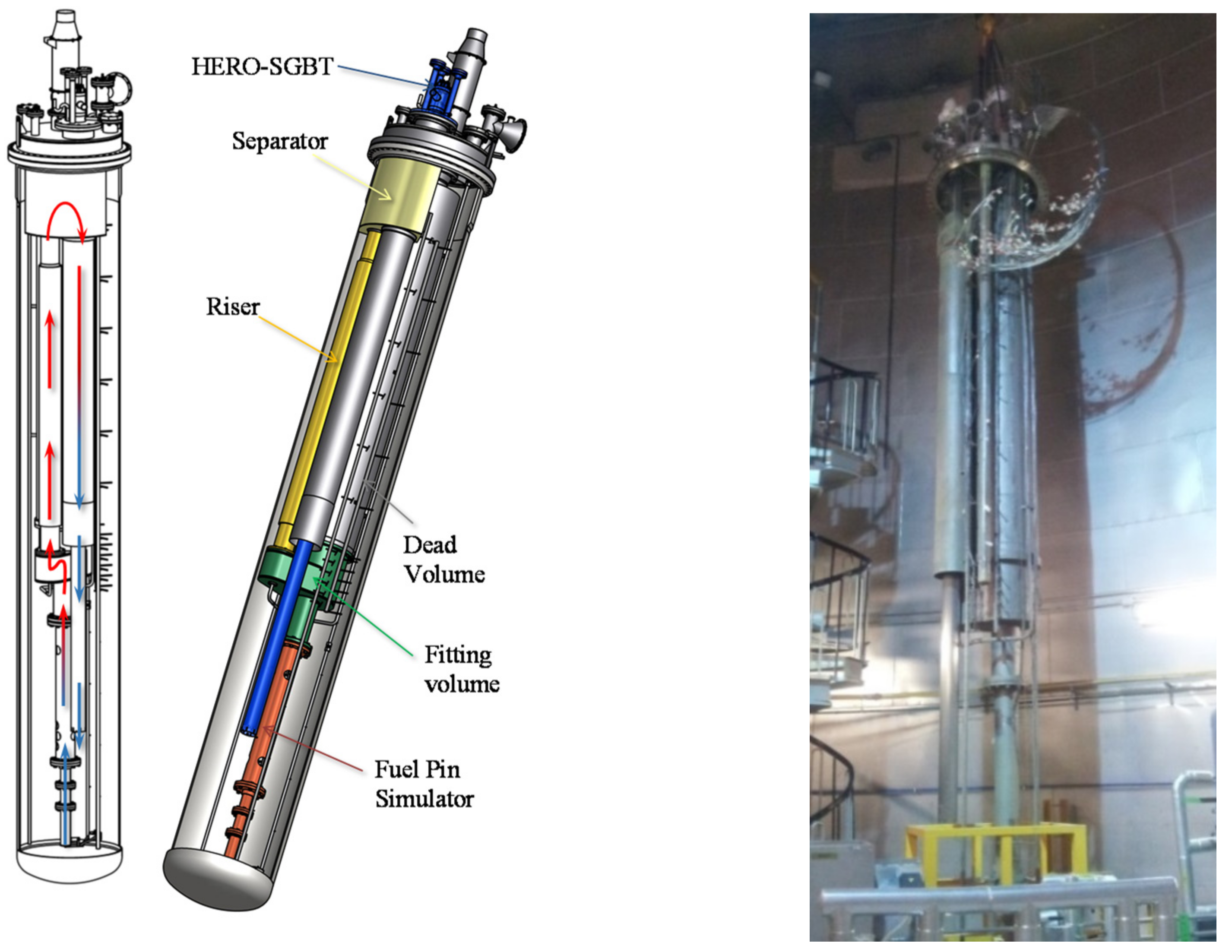
2.2. Steam Generator Tube Rupture Experiments

In the framework of the MAXSIMA project [14], a large-scale test section (TS) was designed with the aim of experimentally investigating the postulated steam generator tube rupture (SGTR) event in a relevant configuration for the Primary Heat eXchanger (PHX) of the MYRRHA reactor [15]. TS was implemented in the large pool-type CIRCE facility, and it was designed for performing four SGTR tests, one at a time, without removing the TS from CIRCE (Figure 3). TS was composed of an LBE and water loop, for simulating the actual condition of the tube rupture postulated to occur in MYRRHA PHX. Four full scale portions of the PHX bundle, composed of 31 tubes, were implemented, conserving the height and flowing areas of both the tube and shell side. Water flowed upwards in the central tube of the bundle (fed by a pressurized tank) and LBE moved downwards in a counter-current direction (pushed by a system of centrifugal a jet pump connected in series).
After reaching the PHX stationary conditions, in terms of the water and LBE pressure, temperature, and mass flow rate, the tube rupture event was caused by a hydraulic jack pulling up the water tube from outside the CIRCE cover. Two different rupture positions were investigated near the lower tube plate (two runs bottom) and between two spacer grids (two runs middle) [16,17,18]. The experimental results highlighted a very satisfactory test repeatability for middle (runs SGTR-A and SGTR-C) and bottom (runs SGTR-B and SGTR-D) rupture scenarios. The couple of runs for each tube rupture position provided very similar pressure (measured in the S100 cover gas), temperature, and strain time trends, showing a high test repeatability. A wide database of high-quality data measurements was formed. Steam evolution in two SGTR configurations was acquired. A domino effect did not occur in any of the tests.
The post-test analysis was performed by SIMMER code in 3D version (Figure 4). SIMMER [19] is a multi-dimensional, multi-velocity field, multi-phase, multi-component, Eulerian, fluid-dynamics code that is able to solve the mass, momentum, and energy conservation equations for different working fluids in the same computational mesh cell. The calculated pressure and temperature time trends are in agreement with the experimental data, providing a contribution to code validation for a water–HLM interaction scenario in a large pool facility. Moreover, the code was able to predict the right timing and amplitude of the pressure oscillations in the cover gas due to sloshing phenomenon in the main LBE pool. SIMMER-IV was also helpful for understanding the steam flow path in the tube bundle, separator, and main pool.

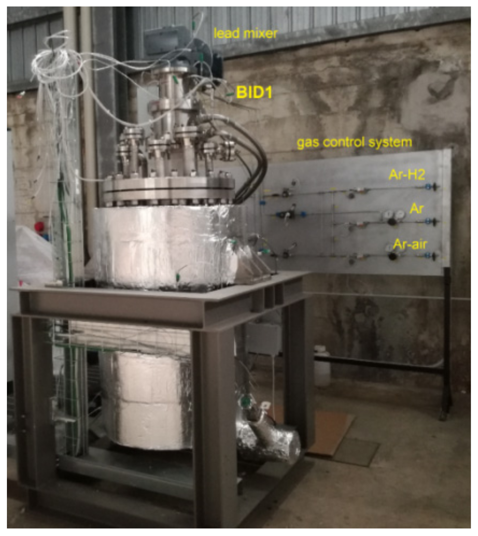
3. Separate Effect Tests on HLM/Water Interaction

LIFUS5/Mod2 is a separate effect test facility installed at the ENEA Brasimone Research Centre. It is designed to be operated with different heavy liquid metals like lithium–lead alloy, lead–bismuth eutectic alloys, and pure lead. It was employed under the THINS [20] and LEADER [21] FP7 EU projects in order to provide experimental data for developing and validating physical modelling, and for improving and qualifying computer codes about HLM/water interaction (i.e., SIMMER code in 2D and 3D version). LIFUS5/Mod2 (Figure 5) consists of two main parts: a reaction vessel (S1) where HLM/water interactions occur and a water tank (S2) pressurized by means of a gas cylinder connected on the top. The water line connects tank S2 with the interaction vessel S1. The water flows from S2 towards valve V14, then the Coriolis flow meter, and finally through valve V4, before it enters S1. Before the injection occurs, a vacuum pump is activated to remove the gas in the injection line. In this way, the injection line is filled by low pressure air when the water injection starts (V14 opening). Therefore, the injected high-pressure water expands and evaporates, flowing towards vessel S1. At the end of the water line, an injector is placed with a variable orifice (from 4 to 12 mm depending on the test), covered by a protective cap, which is broken by the increasing pressure at the beginning of the injection phase.
The THINS experimental campaign [22,23,24,25,26,27] provided high quality data, based on well-defined boundary and initial conditions, for thermo-hydraulic characterization of the HLM/water interaction occurring after injecting water at 16 and 40 bar, from 180 to 240 °C, into a small pool of LBE at a higher temperature. The data obtained on pressure, temperature, strain, water level, and mass flow rate time trends permitted enlarging the experimental database and improving the knowledge of the phenomena. In particular, the experiments aimed at characterizing the formation of the initial peaks, the resulting jet expansion and fragmentation, and the transient and final pressurization of the reaction tank. In addition, the measured data of the LEADER campaign [28,29,30,31] evidenced that the domino effect did not occur in the conservative (lower tube thickness) relevant conditions adopted in the experiments. This constitutes a unique engineering feedback for the helical tube steam generator designers. Finally, the performed tests provided detailed and reliable experimental data useful to modify, calibrate, and validate the SIMMER models for improving the code capabilities regarding the HLM/water interaction (Figure 6). More recently, the LIFUS5/Mod3 facility (the third refurbishment) was employed under the MAXSIMA project [14]. Water was injected through a laser micro-holed plate in order to characterize and correlate the leak rate through typical cracks occurring in the pressurized tubes with signals detected by proper transducers (microphones and accelerometers), applying the leak before the break concept to decrease the probability of the pipe break event [32].

4. Core Design and Safety Assessment

4.1. Core Design Activities

ENEA preserves a set of competences on core design, established since the 1970s with the launch of the PEC project, an experimental sodium-cooled fast reactor whose construction was started at the Brasimone research centre, and then spent in international projects, such as for support to General Electric for the design of some configurations of the PRISM core or the MOX-fuelled variant of the BN-800 core. Upon streamlining these activities, relevant contributions were provided, in the European context, for the rationalization of the guiding and optimization principles for the design of the cores in ADSs.
Since the shift to a programmatic research on the LFR technology, such competences were specialized to the design of heavy-liquid-metal-cooled cores, at first within Euratom co-funded research projects and then to international development projects, such as in support of industrial designers like Westinghouse Electric Company Ltd. or Hydromine Inc., or with a direct responsibility within the FALCON consortium, relative to ALFRED.
A capability is acknowledged to ENEA for developing ad-hoc procedures to establish a core design activity based on a clear focus on the driving rationales, including objectives and constraints, so that these could be met by the resulting configuration by design. Two remarkable examples that were developed in the past are:
  • the so called “42-0 approach” and the support tool “A-BAQUS” for the design of a uranium-free, plutonium isogenerator and minor actinides (MAs) burner core for an ADS [33];
  • the approach for the so called “adiabatic reactor concept”, to design a critical core that targets the isogeneration of plutonium and of MAs, which therefore operates in a closed fuel cycle as a net burner of uranium only [34].
Both approaches stand on a different ordering of the steps typically defining the sequence of considerations to set the configuration of a core, according to which elements pertaining to the fuel cycle (i.e., transmutation performances) are moved early in the sequence, before any neutronic analysis, thereby enforcing the design objectives so that the resulting configuration will target performances of this aim according to design.
The ENEA laboratory for core design, established in Bologna, continues to develop or extend similar design approaches, and to apply them to the design of the core of advanced reactors. This is one of the main reasons ENEA contributes to the FALCON consortium in the role of being chiefly responsible for the design of the ALFRED core.
Along with the general design approach, ENEA develops, validates, and uses, according to its software quality assurance programme, scientific codes, tools, methods, and models for the analysis of all aspects concurring to the characterization of a reactor core. In addition, in this case, ENEA can leverage on the expertise and a number of codes from the past, which have been revitalized and upgraded for application to advanced reactors. Besides new codes that are currently being developed for the thermal-hydraulic and thermomechanical analyses of a reactor core, fuel assemblies, and fuel and absorber elements, examples of recent releases of legacy codes include ANTEO+ [35] for the thermal-hydraulic analysis of a fuel assembly by the sub-channel method and AMARA+ [36] for the adjustment of nuclear data libraries based on integral experiments.
In addition to exploiting these tools, ENEA provides design and analysis services, notably related to LFR technology as the main focus of its development and innovation programs. The services range from leading and coordinating the full spectrum of activities related to the core design, as applied to the ALFRED project within the FALCON consortium, to supporting external organizations with the setting and characterization of core configurations. In both cases, analyses are also performed internally, covering mainly neutronics, shielding, criticality safety, thermal-hydraulics, and fuel thermomechanics.
With regard to all of the activities above, extensive international collaboration was pursued, also through participation with associated working groups within the main international and European organizations, such as the IAEA, the OECD/NEA, and the EU SNETP’s ESNII.

4.2. NACIE Experiments, CFD Applications, and Flow-Induced Vibration Experiments

A large experimental and numerical work was undertaken at ENEA on FPS technology. The work included the design of the experimental test section, the experiments, and the use of numerical tools to predict the instrumentation position and to validate codes. This work concerned mainly the two experimental facilities NACIE (NAtural CIrculation Experiment) and CIRCE. Both wire-spaced and grid-spaced fuel pin bundles were investigated. Experiments were carried out within EU Projects (THINS, SEARCH, and SESAME) and the ADP-PAR National program.
NACIE-UP is a rectangular loop in which there is a difference in height (5 m) between the heat source (FPS) and heat sink (HX), which allows for natural circulation. Forced circulation is guaranteed by a gas-injection (Argon) in the riser of the facility—the gas lightens the riser and the hydrostatic unbalance between the two columns will provide a positive pressure head. This method is called gas-lift. A prototypical thermal flow meter measures the mass flow rate. Thermocouples provide temperature distribution in the loop, while the FPS test section is highly instrumented with about 70 TCs.
A 19-pin MYRRHA-like 250 kW wire-spaced FPS was designed, procured, and installed in the NACIE-UP facility. In the first experimental campaign, data on local and overall heat transfer were produced. Uncertainty analysis was performed on the derived data. For the overall heat transfer, the results showed values between the Carelli–Kazimi and the Mikityuk correlations, and the slope of the experimental trend was very similar to the correlations, see [37] for a complete discussion of the results.
With the same test section and the same facility, a few transient experiments were carried out within the SESAME EU project. The three fundamental transient tests concerned transients with gas lift transition, power transition, and a combination of the two (power and gas reduction (PLOFA)), respectively, and focus on the study of the thermal-hydraulic behavior of the loop and the bundle during power and mass flow. A strong subchannel rank effect emerged from the experimental data, with the central subchannels being hotter than the peripherals ones. As was expected, the temperature difference increased going from section A (lower) to section C (upper) because of the developing thermal conditions. Lots of data, both integral and local, were produced and published [38,39,40], and were used as reference data for an international benchmark.
Additional tests were carried out with just a few pins switched on, and the results were compared with the uniformly heated case. The obtained experimental data provided useful information for the characterization of the bundle and the computation of the heat transfer coefficient. Moreover, the collected system data could be used to qualify the STH codes, whereas the local fuel bundle data, especially the ones from non-uniformly heated tests, could be useful for the validation and benchmarking of CFD codes and coupled STH/CFD methods for HLM systems. The CFD post-test analysis exhibited a good agreement with the uniform case, with an rms error on the temperature probes of 5 °C (see Figure 7). For the non-uniform cases, the error was higher (15 °C rms error). The results were published and discussed in [41].
Finally, the experimental data on the CIRCE grid-spaced fuel pin bundle were compared with numerical simulations, and the results showed a good agreement with the values of the Nusselt number close to the Ushakov correlation [42].
A large experience exists at ENEA on the Fuel Pin Bundle simulators, experiments, and numerical simulations. ENEA Brasimone has unique experience in managing Pin bundle simulators cooled by HLM, and for designing and performing experiments in this field.

4.3. Flow Blockage Experiments, ALFRED Analysis, ALFRED Design FA

The blockage FPS (BFPS) test section installed into the NACIE-UP loop facility aimed to carry out suitable experiments to fully investigate the different flow blockage regimes in a 19 fuel pin bundle, providing experimental data in support of the development of ALFRED (Advanced Lead-cooled Fast Reactor European Demonstrator). A preliminary analysis of this topic on ALFRED FA can be found in [43]. The procurement and commissioning of the test section was enclosed in the framework of the H2020 project SESAME on the thermal-hydraulics of liquid metals.
This fuel pin bundle configuration was relevant for the thermal-hydraulic design of the ALFRED core. The main parameters of the BFPS test section and ALFRED core are reported in Table 1 for comparison.
A proper experiment was designed in order to describe the thermal-hydraulic behaviour of a simplified version of FA during an internal flow blockage accident, simulated by blocking some holes of the first spacer grid (at the beginning of the heated length) with appropriate caps.
The central spacer grid is the key component of the flow blockage experimental campaign, and it is described in the following.
For the flow blockage configuration, several caps were displaced on the different holes of the central grid; those caps were small thin plates of an appropriate shape positioned by moving rods from the bottom to fix a configuration.
Because of the internal flow blockage, the temperature of the pins near the blockage increased due to a lower cooling rate in this region (Figure 8). The extension and magnitude of these hot regions were strictly related to the blockage type and blocked flow area of the grid.
The experiments investigated the blockage on a spacer grid at the beginning of the active region. A proper pre-test analysis [38] allowed for fixing the bundle instrumentation in an improved way. The results showed a local maximum behind the blockage: the experimental results were unique and were published together with the associated CFD post-test analysis [44]. CFD simulations with RANS and URANS methods were qualitatively in agreement with experimental data. CFD overestimated the peak temperature, and the LES method is probably needed to correctly capture the flow features.

4.4. CFD Assessment of Flow Blockage in ALFRED FA

CFD analyses were employed to model and simulate the internal flow blockage in a grid-spaced HLM cooled fuel assembly of the Generation IV reactor ALFRED [45].
Concerning the numerical simulations of ALFRED FA, an appropriate CFD model and computations of the ALFRED FA in the nominal configuration, as well as different types of internal blockages were developed and run. In particular, different types of blockages at the spacer grids were studied by CFD RANS simulations. First, a CFD model was created to keep into account the main physical phenomena involved. Then, the model was applied to predict different blockages. The accumulation of debris in the three main spacer grids was considered as follows: lower spacer grid (200 mm upstream the active region), middle spacer grid (at the centre of the active region), and upper spacer grid (100 mm downstream the end of the active region). Three different types of blockages were considered, namely: one sector (β = 0.15), two sectors (β = 0.30), and corner blockage (β = 0.15).
The results showed that blockages in the middle spacer grid (active region) produced very significant effects, and serious damage of the clad was foreseen for any type of blockage larger than a sector (about 16% of the total flow area).
The results for the lower spacer grid showed the presence of the recirculating vortex extended downstream well inside the active region for the most severe case (two sectors).
The results for the upper spacer grid (downstream the active region) showed that, even in the most severe case of two sector blockage, the velocity field in the active region was marginally perturbed and the temperature field was slightly different from the no blockage case 0. Therefore, blockages in the upper spacer grid produced minor effects on the clad temperature and were not relevant from a safety point of view.

5. Numerical Tools for LFR

In the field of nuclear technology, best estimate codes [46] are employed with broad scopes, ranging from design or safety assessment, including licensing. Their applications to LWRs are, in general, recognized and accepted, thanks to an extensive and well documented qualification database. Best estimate computer codes have various levels of qualification: this depends on the V&V documentation, the availability of experimental data or nuclear power plant data, and the extent of independent assessments. Experimental data [47] are fundamental for supporting the development and demonstrating the reliability of computer codes in simulating the behavior of a nuclear power plant, or its systems and components, during normal operation or a postulated accident scenario: in general, this is a regulatory requirement. However, the user [48] always has the responsibility of the appropriate use of such codes. Validation and verification [49] are essential steps in qualifying any computational method, and are the primary means of assessing the accuracy of computational simulations. Indeed, when LFR design is concerned, the applicability of the code models, frequently relying on empirical correlations, shall be demonstrated.
To fulfill this scope, ENEA has employed R&D efforts on code modifications, model improvements, and V&V, with particular emphasis on system thermal-hydraulic (i.e., RELAP5), severe accident/multifluid (i.e., SIMMER discussed in Section 3), fuel pin performance (i.e., TRANSURANUS), fuel element thermal-hydraulics (i.e., ANTEO+), and computational fluid dynamic codes.
RELAP5 (i.e., RELAP5/Mod3 [50] and RELAP5-3D [51]) has a general structure and can perform simulations with heavy liquid metals as working fluids. In order to do this, the code has been modified to simulate the LBE, Pb, and PbLi systems [52,53,54,55]. The modifications were carried out in the framework of a larger activity aimed at setting-up a code capable of dealing with HLM for Generation IV and fusion applications (i.e., implementation of LBE, Pb, PbLi, HITEC properties, helical coils heat exchanger, and steam generator heat transfer correlations, etc.).
Validation activities have been performed, starting from the LFR design and the analysis of the phenomena relevant for the simulations. Experimental data have been used to evaluate the reliability of the code results and, to some extents, also the accuracies of the predictions. Simulations of the separate effect test facility data, based on NACIE tests [56,57,58,59,60] (see also Section 4.2), were aimed at validating the core related thermal-hydraulic phenomena (e.g., heat transfer, wall to fluid friction, transition from forced to natural circulation, and single-phase natural circulation) occurring in normal operation and accidental conditions (e.g., flow blockage). Other phenomena, such as pool thermal-hydraulics phenomena, thermal mixing, multidimensional coolant temperatures and flow distributions, and heat transfer in prototypical steam generators have been assessed, together with the overall performances of the code at a system level, using integral test facility data based on CIRCE [13,61,62] experiments (Figure 9) and, in some cases, using sodium fast reactor [63,64] data (Figure 8), released in the framework of international benchmarks (i.e., EBR-II and PHENIX, Figure 10).
Concerning the fuel performance codes, the main issues to be investigated in LFR technology are [65] (i) high burn-up performance in normal operation, (ii) fission gas release and inner pin pressurization in steady state and transient conditions, (iii) cladding performance with respect to fuel-clad mechanical interaction and fuel-clad chemical interaction phenomena (steady state and transient), and (iv) fuel and cladding nuclear qualification in lead environment.
The first two items can be, in principle, investigated on the basis of the existing sodium cooled fast reactor (SFR) experimental databases. The third item requires selecting a cladding material that has been tested in the SFR technology in order to take advantage of the existing experimental databases. The fourth item differs because lead-clad compatibility is introduced.
TRANSURANUS code [66,67], as the fuel pin performance codes in general, relies on empirical models developed on the basis of the experiments. It can deal both with LWR and FR fuels, and includes lead and LBE coolants, thanks the modelling improvements focused on Generation IV reactors, MYRRHA, and ALFRED (Figure 11, Figure 12). These R&D activities are pursued in the framework of EU projects [68,69,70,71] and national programs [72,73,74,75] to cope with gaps in the simulation performances.
The development of STH/CFD (System Thermal Hydraulics/Computational Fluid Dynamics) is becoming increasingly interesting for the simulation of complex thermal hydraulics analysis in support of the design of the LFR nuclear system [79]. 1D STH numerical codes are considered one of the most relevant tools in the licensing process of nuclear power plants. These tools implement complex and well proven numerical models for single- and two-phase flows, nevertheless, they are not able to accurately reproduce the intrinsically 3D phenomena that may occur in large pool and complex geometries. As an alternative, the simulation of turbulent flows in complex 3D components is one of the key features of the CFD approach, along with an increase in the computational effort. According to the scheme reported in Figure 13 in a coupled simulation, the geometry or domain to be analysed is divided into regions that are modelled using CFD and regions that can be reasonably well simulated using the STH code (non-overlapping domain). This partition identifies the interfaces where thermo-fluid-dynamics data are transferred from the system-code-portion to the CFD-code-portion and vice versa (two-way coupling). The execution of the STH and CFD codes is operated by an appropriate MATLAB script, where a processing algorithm is implemented, allowing for receiving boundary conditions (b.c.) data from CFD, at the beginning of the STH time step, and to send b.c. data to the CFD code at the end of the STH time step.
The developed tool was applied to the simulation of experiments on both loop and pool type configurations for HLM facilities [80,81]. The coupled procedure was verified checking the numerical outcomes against the experimental data, proving better results compared with the STH stand-alone simulation, requiring detailed information at very fine spatial and time scales (CFD domain) as well as integral information on the remaining parts of the facility (STH domain). As an example, the outcome for the 3D CFD domain coupled simulation (coupling and geometrical model (Figure 14, left) for the LBE mass flow rate toward the test section is presented in Figure 14 (right).

6. Conceptual Design of Auxiliary Systems for ALFRED

6.1. Fill and Drain System

Because of the relatively high temperature and properties of liquid metals, reactor vessel filling and draining procedures present some unique operational and safety aspects. Experiences on coolant handling on HLM reactors were acquired in the past with the operation of SFR such as Superphenix [82] in France, Monju [83] in Japan, and BN-600 and BN-800 still in operation in Russia [84]. Nevertheless, differences in the thermo-physical properties (lead high density and high melting temperature) and in the chemical reactivity do not allow for a complete technological transfer from SFR to LFR. According to the filling and drain (F&D) operation experienced on the existing experimental facilities operated at ENEA Brasimone R. C., a preliminary Process Flow Diagram (PFD) concerning ALFRED F&D is drafted and reported in Figure 15.
In principle, the required procedure to be considered during F&D can be defined as (i) pre-oxidation of internal structures, (ii) gas conditioning sequence (inertization), (iii) preheating, (iv) coolant preparation (lead/LBE melting and purification), and (v) lead charging and draining.
Pre-oxidation is recommended before filling the system for the first time in order to produce a protective oxygen rich layer on all internal metallic structures to reduce/prevent steel alloy element dissolution. This procedure pre-heated the structures in the temperature range of 250–450 °C, and exposed them to air for 24–48 h. This phase was then followed by the degassing procedure (inertization), where the oxygen content in the piping/vessel was reduced using purge gas, with the aim to avoid further oxidation of the structural material during the preheating phase. This procedure could be accomplished by evacuating the air from the facility using a vacuum pump, followed by flushing the facility with inert gas. The preheating phase was essentially required in order to avoid thermal shocks and any liquid metal frozen issues during the changing of the coolant. Preheating was done with electric heating cables installed on the outside surface of the piping and the transfer tank, while heated argon gas was be considered for heating the main and storage vessels.
The lead ingots were then melted in the melting vessel and the melted lead was transferred by gravity into the storage tank. The melting procedure was performed at a temperature as low as possible without risking localized freezing (about 380–400 °C for lead). The reason is that the saturation concentration of impurities inside the melt decreased with the temperature; therefore, by reducing the temperature during the melting and transfer procedures, the amount of impurities dissolved in the melt and transported by it, was reduced. Moreover, in order to reduce O2 contamination, melting should be performed under a heavy inert cover gas such as argon. It is advisable to proceed to the coolant purification before the filling procedure, performing a deoxydation of the molten lead. This procedure could be accomplished inside the storage tank, where a proper oxygen conditioning system should be installed (e.g., flushing Ar/H mixture in the storage tank).
Finally, the lead at a low oxygen concentration can be charged in the main vessel. This can be done by gravity, pump, differential pressure, or a combination of both. Indeed, the melted lead was picked in the lower part of the melting vessel (oxides will float at the free surface and a siphon was used in the connecting pipeline to avoid transferring floating oxides and impurities) and transferred by gravity to the storage tank though a dedicated pipeline mounting filters to avoid the accidental transport of lead oxides. Once again, the melted fluid was transferred by gravity from the storage to the transfer tank. It is advisable to keep the transfer tank pressurized at a pressure slightly below that required for the filling of the transfer tank. In doing so, the velocity of the fluid was reduced during the filling procedure. Then, the filling of the reactor vessel from the transfer tank was done by pressurizing the transfer tank with Ar inert gas. In order to minimize the costs, the transfer tank, designed to withstand high pressures, was smaller than the storage tank. The drawback of this solution is that the transfer processes require more time as there are a higher the number of steps required to complete the transfer.

6.2. Cover Gas Purification System

In the last years, ENEA Brasimone has been involved in activities relevant to the design of auxiliary systems for the ALFRED reactor. The cover gas purification system is one of the auxiliary systems studied here. Figure 16 shows a simplified process flow diagram relevant to a preliminary conceptual design of the ALFRED cover gas purification system. For reliability reasons, some of the components shown in Figure 16 should be composed of two identical devices (for example filters and circulator). At the exit of the reactor, before entering the purification system, the loop shows three different types of traps, placed to remove aerosol, vapour, and dust (condenser/separator, vapour trap and filter). A circulator drives the gas to be purified. At the inlet of the purification system, the gas is heated at the operating temperature of the oxidizing bed (approximately 250 °C). The oxidizing bed, using a catalyst based on copper oxide, has the scope to oxidize Q2 (Q = H, D, and T) and CO into Q2O and CO2. The filters, placed after the oxidizing bed, have to remove the powders released by the catalyst. A gas–gas heat exchanger (economizer) and a water cooler reduce the gas temperature to approximately the room value. A molecular sieve bed, using zeolites, removes Q2O and CO2 from the gas flow. Generally, two molecular sieve beds are present, one working in the purification phase and the other one in the regeneration phase. At the exit of the molecular sieve bed, the filters removed the powders released by the zeolites. Then, an economizer decreased the temperature of the gas entering the cold delay bed; this component used activated carbon at liquid nitrogen temperature to remove mainly Xe isotopes. The distillation column after the cold delay bed was used mainly for the removal of Kr isotopes. Before exiting the purification system, the argon was heated passing through two economizers.

7. Structural Materials, Coatings and Coolant Chemistry

7.1. Structural Materials and Mechanical Tests in Lead

The use of lead as a coolant deeply affects the behaviour of the steels with which it comes into contact, not just in terms of corrosion, but also in terms of LME (liquid metal embrittlement) [85]. This phenomenon is still nowadays not fully understood, and is known to be deeply affected by the microstructure, surface conditions, temperature, and strain rate. Even if the occurrence of LME is mainly related to a range of low temperatures (the so called “ductility through” [86,87]), some literature references [88] also report detrimental effects of HLM contact on creep resistance. In order to study LME on austenitic steels (if present), an experimental campaign was planned (both slow strain-rate tensile (SSRT) tests and creep tests) aimed at comparing the mechanical properties in air and in contact with the liquid lead. In this frame, ENEA activities were co-funded by the GEMMA project lasting 4 years (2017–2021).
SSRTs were carried out on cylindrical specimens (4.5 mm, 20 mm gauge length) extracted in a longitudinal direction (with the axis of the specimen parallel to the rolling direction) from the 316L plate. The adopted standard is the ASTM G129-00. The test temperature is controlled by means of a resistance furnace and the stress by means of a 100 kN load cell installed on a hydraulic machine. The strain is controlled on the shaft connected to the sample by a couple of magnetostrictive linear position sensors (MLPSs) and measured the gauged length of the specimen using an axial extensometer (12 mm gauge). The strain rate was kept constant in a range between 10−4 and 10−6 s−1 according to the corresponding test condition. The whole instrumentation is reported in the picture below (Figure 17a). A similar approach was followed in the creep tests as well, with the “external” measurement of the deformation (Figure 17b). These external linear variable displacement transformers (LVDTs) are meant to record the deformation for comparison with the future tests in liquid lead, where it will not be possible to attach the LVDTs directly to the sample (flooded in lead), but only these last “external” LVDTs will be left. For the creep tests (ASTM E139:11), several frames (1:10 and 1:15 lever ratio) equipped with auto-levelling arm devices and three zone P.I.D. controlled furnaces were employed. By means of a couple of LVDT mounted on each specimen, the deformation of the gauged length of the sample was recorded during the test (Figure 17c,d).
In order to carry out the tests in lead with controlled oxygen content, a devoted test section was designed internally in ENEA and was fabricated by an external company. Figure 18 reports a drawing accompanied by a picture of the test section. An inlet and outlet for the gas were aimed at lead conditioning by inert gas (Argon/H mixture) addition. The oxygen measurement was achieved by means of an ad hoc developed Al2O3 probe. The test temperature was controlled by means of a resistance furnace and the stress by means of a 100 kN load cell installed on a hydraulic machine. The strain was controlled on the shaft connected to the sample by a couple of MLPSs. The axial extensometer (12 mm gauge) attached to the gauged length of the specimen during the tests in air was removed during the tests in lead. The strain rate was kept constant in a range between 10−4 and 10−6 s−1 according to the corresponding test condition.
The first tensile curve achieved by SSRT in lead at 550 °C on the AISI316L base material is compared to the tests in air in Figure 19; there is no substantial difference (apart from some small scatter within the statistical spread of the results related to the material) with the corresponding tests in air. Therefore, we can state that the 316L base material does not seem to be affected by LME, at least on the basis of this first test at 550 °C.

7.2. Advancements in Corrosion Studies and Coatings Technologies

As for a corrosion moderation strategy to be applied on structural materials exposed to a liquid metal environment, ENEA is setting up protective coatings using ceramic compounds deposited via different deposition techniques. The actual candidate material is the aluminum oxide (alumina), which has demonstrated a high chemical inertia and stability in this specific environment.
Besides resisting corrosion, ENEA is committed to realizing protective coatings that also offer good adhesion to the underlying substrate, accommodating any mechanical stresses (e.g., thermal expansion mismatches), a low swelling rate, and a stable microstructure that resists high irradiation doses. Furthermore, the self-healing would be a very desirable property, as it allows for coating regeneration by the reaction with some environmental components in the case of a surface failure (e.g., a crack and a scratch). The coating deposition should be a low temperature process to avoid steel property variations that could affect its behavior under neutron irradiation. Consequently, protective strategies such as diffusion coating, which involves exposure to high temperatures for a long time to allow for the formation of the diffusion top-layer, were ruled out. On the other hand, some low temperature processes like Fe-Cr-Al pack cementation gave a good anti-corrosion performance, although with scarce diffused layer thickness and roughness.
Among the metallic coatings, both Fe-Cr and Fe-Cr-Al alloying gave an excellent anti-corrosion performance in oxygen-rich liquid lead after 5000 h of exposure at 500 °C. In particular, Fe-Al coatings displayed remarkable resistance with neither erosion nor corrosion signs at the surface (Figure 20).
Such coatings have been realized by using different techniques (e.g., magnetron sputtering, high velocity oxygen fuel thermal spray, and arc-PVD), and long-exposure corrosion experiments in flowing liquid lead as well as high temperature mechanical tests are currently underway. Besides, other critical properties still need to be assessed such as the resistance to the irradiation structural damage (causing swelling, irradiation creep, instability of the microstructure, and changes in mechanical properties) and the adhesion strength. Indeed, in order to protect the underlying structural material from corrosion, the coatings need to maintain unaltered properties during neutron irradiation (e.g., 100 dpa is about the dose after 5 years of irradiation in the ALFRED reactor core, after which a fuel element is expected to be replaced during refueling).
Regarding the ceramic coatings, research at ENEA has been focused, in particular, on the deposition of Al2O3 coatings deposited by detonation gun thermal spray (D_Gun), pulsed laser deposition (PLD), and atomic layer deposition (ALD). In particular, D-Gun [90] is a low-cost thermal spray deposition technique that allows for depositing metals and ceramics quickly and in a wide range of thicknesses (from few up to hundreds of micrometers), providing coatings with an extremely good adhesive strength, low porosity, and some compressive residual stresses. In brief, during the process, a combustion mixture and the coating precursors powder are fed through a tubular barrel simultaneously (the gun in Figure 21). The gas mixture is then ignited, generating a high-pressure detonation wave that propagates through the gas stream. The hot gases with temperature up to 4000 °C travel down the barrel melting and accelerating the powder particles up to about 1200 m/s. Once impacting the surface to be coated, the high kinetic energy particles give a very dense, low porosity and strongly adhered coating.
Moreover, although the powders reach temperatures up to 4000 °C the substrate temperature remains relatively cold (between 100–200 °C) as the deposition advances shot-by-shot by spraying small amounts of powder, thus leaving time for the underlying steel to cool down. The technique is also versatile because it allows for the deposition of layered architectures with alternate compositions, as well as the deposition of variously mixed precursors to attain coatings with specific stoichiometric ratios. Importantly, the D_Gun technique is a fast coating process, and thus it is, for instance, particularly suitable to cover the large surface of the reactor vessel with a thick alumina protective layer (Figure 22).
ENEA in collaboration with the Italian Institute of Technology (IIT) is pursuing the realization of ceramic oxide anti-corrosion coatings through the pulsed laser deposition (PLD) technique. PLD uses high power laser pulses to enable a laser ablation process that converts the coating precursors into a plasma. When this plasma is directed toward the substrate surface, a thin and compact film is deposited. PLD is a quite versatile technology that allows for depositing thin films of a wide range of materials. By adjusting the deposition parameters, the coating microstructures can be manipulated spanning from a dense and compact film to a columnar and porous structure [91]. In particular, dense and compact Al2O3 coatings have been growth by PLD on various steels, whose structure consists of a homogeneous dispersion of ultra-fine nanocrystalline domains (6 ± 4 nm) in an amorphous alumina matrix (Figure 23) [92].
Interestingly, this kind of coating displays metal-like mechanical properties (E = 195 ± 9 GPa, ν = 0.29 ± 0.02), and a plastic behavior (unusual for ceramic materials), strong adhesion, and a relatively high hardness (H = 10 GPa) [91,92]. Alumina barriers on steel by PLD have been tested against corrosion up to 600 °C in stagnant liquid metals with remarkable results [93], while long-term (>10,000 h) exposure in flowing lead and thermal creep experiments on coated 15-15 Ti specimens are underway. Alumina coatingds deposited by PLD are among the most promising to protect the core components from corrosion.
Moreover, ENEA is part of a broad project dealing with irradiation effects on coated steels. In this framework, the performance of the alumina films under heavy ion irradiation up to a 150 dpa dose (similar or worse than the foreseen damage in the ALFRED reactor) were investigated during experiments at 600 °C. By increasing the irradiation dose, a well-defined nanocrystalline structure developed, leading to the growth of the grains (Figure 24). Indeed, the average grain size increased from about 6 nm to about 100 nm at 20 dpa, 153 nm at 40 dpa, and about 290 nm at 150 dpa. Moreover, the crystalline structure also underwent a change, transforming from a γ-Al2O3 (up to 40 dpa) to a mixed γ and α-Al2O3 structure at 150 dpa. Importantly, the irradiation did not cause any detachment or delamination at the film–substrate interface [94].
Finally, coatings are going to be developed also to handle tritium in LFRs. Following the ternary fissions in the reactor fuel and the neutron interaction with the boron carbide rods, the generation of tritium is expected in LFR. Anti-permeation and anti-corrosion coatings are being developed in order to reduce tritium permeation from lead to the heat exchangers of ALFRED. In the context of TRANSAT (TRANSversal Actions for Tritium) project, the APRIL (Alumina-coating for tritium Permeation Reduction for Innovative LFR) experimental facility was designed and is currently under construction in ENEA Brasimone R.C. APRIL aims at testing, in static conditions, the performances of coatings in nanoceramic alumina, deposited with the PLD and ALD techniques. The permeation reduction factor of each coating type will be evaluated by comparing the permeate fluxes through bare and coated pipes. In APRIL, tests are currently conceived to be done in gas: deuterium (that simulates tritium) migrates from a chamber filled with a mixture of argon and deuterium into pipes filled with pressurized steam. The steam will be kept at ALFRED relevant conditions (480 °C and 100 bar). Figure 25 shows the P&ID of APRIL facility.

7.3. Lead Coolant Chemistry Control for ALFRED Design: Overview on the R&D Activity

The control of the chemistry of the lead coolant is a key point to be addressed for the development and design of LFR and ALFRED. Specifically, the control of the oxygen concentration and the management of the corrosion products is fundamental. The oxygen control and the purification system from corrosion products are also strictly linked each other, as the oxygen concentration dissolved in lead influences the magnitude of the corrosion of structural steels, and thus the release of corrosion products [95].
Oxygen is required in the coolant at a sufficient level to allow for the formation of an oxide layer on structural steels surface (passivation), which minimizes the dissolution of the alloy elements (Fe, Cr, Ni, and Mn) in the coolant. On the other hand, oxygen saturation in the coolant must be avoided in all the parts of the reactor system to prevent the deposition of PbO, which may have plugging effects on the circulation, especially in the cold points (i.e., heat exchanger and steam generator) [95]. In addition, oxygen interacts with corrosion products, forming their respective oxides, and corrosion products may also have a plugging effect.
In this context, the choice of the materials and operating conditions influences the management of the oxygen and corrosion products in the lead coolant. In general, bare structural steels are sensitive to oxidation/passivation and dissolution, whereas alumina-coated steels or alumina-forming steels are not expected to interact with oxygen and lead significantly. Thus, the consumption of oxygen and the release of corrosion products is expected to be negligible or low when most of the steel surfaces are coated or highly corrosion-resistant. On the other hand, high consumption of oxygen for oxidation and dissolution is expected for bare steels, with the entity of these effects increasing with the operative temperature. In addition, the protection of bare conventional steels by self-formation of the oxide layer and oxygen addition to the coolant is reckoned to be effective only in a low temperature window, ranging from 450 °C to about 500 °C.
According to the operation strategy of ALFRED, various stages have been foreseen with different temperature windows in which the power and the core outlet temperature are progressively increased [96,97]. For a given stage, different structural materials are foreseen according to their capability to resist corrosion (Table 2). Stage 1 will operate with lead at a low temperature and oxygen control (10−6–10−8% wt.) and, in these conditions, oxygen is expected to form a protective oxide layer on candidate steels preventing strong dissolution. Conversely, in later stages, non-protective oxidation and corrosion are expected for bare steels with the same oxygen concentration range. Thus, to face corrosion, alumina-based coatings or advanced materials are foreseen in later stages for all structures and components, except for the reactor vessel.
The control of the oxygen concentration in lead requires procedures and devices to achieve and maintain the target concentration, considering potential deviations towards higher content (e.g., oxygen contamination) or lower content (e.g., oxygen gettering by steel walls for passivation). In addition, devices are needed to monitor the concentration in the coolant during operation. Regarding this, ENEA is involved in R&D activities on oxygen monitoring and control to support to the design of a chemistry control system in ALFRED.
Potentiometric sensors based on ceramic solid electrolytes are foreseen to monitor the oxygen concentration in lead. The sensors are manufactured and tested in the RACHEL laboratory, and different configurations are under implementation for facility scale systems (loop and pool facility). For laboratory scale and capsules, small sensors were, in principle, tested in capsules using different internal reference electrodes (Pt-air, Bi/Bi2O3, and Cu/Cu2O) and using YPSZ (Yttria Partially Stabilized Zirconia) as the conductive material for O2- ions [98,99]. The type of internal reference electrodes used influenced the “minimum reading temperature”, e.g., the minimum temperature to which the experimental output given by the sensor is in accordance with the Nernstian extrapolation in oxygen-saturated Pb/LBE. For the internal electrodes investigated, this minimum reading temperature was Cu/Cu2O (200 °C) < Bi/Bi2O3 (300 °C) < Pt-air (400–450 °C) [98]. Recently, internal air-based references made of LSM-GDC (Lantanum–Strontium–Manganite–Godolinia-Doped Ceria) and LSCF-GDC (Lantanum–Strontium–Cobalt–Ferrite–Godolinia-Doped Ceria) powders were tested in 400 mm sensors, improving the performance compared with the standard Pt-air reference in oxygen-saturated LBE (Figure 26).
To investigate the oxygen monitoring and control capability in larger facilities, the implementation of sensor prototypes 1000–1400 mm long and Pt-air reference is ongoing [100]. The configuration is still under improvement to increase the reliability and repeatability of the measure, but preliminary results indicate a good performance after testing in a lead storage tank containing a large volume of Pb (about 285 L) in the range 400–480 °C (Figure 27). The adaptation of this configuration is ongoing with other air reference systems to increase the capability of measuring at lower temperatures.
The oxygen control methods for Pb/LBE systems include the injection of reactive gases (gas-phase methods) or the use of reactive solids (solid-phase methods). H2 and/or O2 gases have the main advantage of allowing efficient adjustment of the oxygen content [101,102], and good control has been obtained in small devices and loop facilities with the injection of the buffer H2/H2O mixture [103]. PbO MX is used as solid-phase oxygen supply source, and has been used and tested in some experiments [104,105]. Solid oxygen getters materials (e.g., Mg) have been used in few experiments to reduce the oxygen content in Pb alloys [106] and need further study.
Between the various methods, gas injection with H2 + O2 is under implementation in ENEA facilities. The combination of H2 + O2 diluted in argon is effective at balancing the concentration, by exploiting automated injections based on sensor output. On the contrary, a single Ar-H2 injection is not able to control the oxygen concentration to the target value and to balance the oxygen gettering effect of materials in contact with lead. An example is given by the oxygen concentration obtained during experiments in capsules in the laboratory (5.5 Kg of liquid lead), as shown in Figure 28. The system based on the H2+O2 combined injection is now implemented in most of the facilities in Brasimone so as to operate under oxygen-controlled conditions and study oxygen control methods via gas-phase, such as in the case of the BID1 pool facility (see Figure 29).

8. Conclusions

To bridge the “death valley” between the HLM experimental facilities and the LFR commercial deployment, DEMO-LFR ALFRED was addressed as being mandatory in the European framework, with the main goal to fill the gap from basic research to market penetration, typically suffering from lack of investment. ENEA is strongly involved in this task.
According to the present overview, a first prioritization of R&D needs is here outlined, even if not fully exhaustive, which takes into account also the actual worldwide level of knowledge on LFR technology.
The R&D needs for the further development of LFRs include the following:
the development and characterization of oxygen control systems suitable for large pools and experiments on lead conditioning in large pool systems;
corrosion assessment in lead and experiments to address mechanical properties’ degradation in lead;
fuel assembly thermal-hydraulics characterization and, subsequently, tests on deformed bundles for safety assessment;
tests on flow-induced vibration (FIV) and flow blockage;
steam generator (SG), deep coolers (DCs), reactor circulation pump (RCP), isolation condenser, and other components’ performance and reliability assessments in large pools;
steady state and transient tests in large lead-cooled pools, aiming at investigating the thermal-hydraulics behavior of LFR primary systems; an experimental database will be made available for code verification and validation (V&V);
steam generator tube rupture (SGTR) experiments in relevant conditions for LFRs;
experiments on fuel–coolant interaction, fuel dispersion and relocation, fission products (FPs) retention and polonium retention are considered to have high priority because of the lack of data in these fields;
tests of the fuel handling system and manipulator, which are mandatory to complete and sustain the licensing process of the LFRs.
Finally, high priority is assigned to code V&V. The experiments mentioned above shall serve to support the deterministic approach to the license of the LFR reactor and, in parallel, to make available an experimental database for code validation.
It is strongly recommended that the design of each of the experiments will take into account this specific objective, allowing for a speed-up of the licensing process, as well as improving the design support of LFR.

Author Contributions

Data curation, M.T., M.A., S.B., S.C., C.C. (Chiara Ciantelli), C.C. (Carlo Cristalli), A.D.N., I.D.P., D.D., M.E., A.F., G.G., F.L., P.L., R.M., D.M., F.P., C.S., M.U., and A.V.; writing—original draft preparation, P.L.; writing—review and editing, M.T., P.L. and D.M.; supervision, M.T.; project administration, M.T., A.D.N., M.A., I.D.P., G.G., D.M. and M.U.; funding acquisition, M.T., A.D.N., M.A., I.D.P., G.G., D.M. and M.U. All of the authors have read and agreed to the published version of the manuscript.

Funding

The work described in this paper summarizes the European collaborative efforts from the following projects, which have received funding from the Euratom research and training program under grant agreements no. 36439 (ELSY), no. 516520 (EUROTRANS), no. 36469 (VELLA), no. 249677 (HeLimNet), no. 249668 (LEADER), no. 295736 (SEARCH), no. 323312 (MAXSIMA), no. 249337 (THINS), no. 945341 (PASCAL), no. 945077 (PATRICIA), no. 662186 (MYRTE), no. 654935 (SESAME), no. 755269 (GEMMA), no. 754586 (TRANSAT), no. 847715 (PIACE), no. 754329 (INSPYRE), and no. 945022 (PUMMA). The work described in this paper was also funded by the Italian Minister for Economic Development (MiSE) in the frame of the FRAMEWORK AGREEMENT (ADP) MiSE-ENEA (2010–2018). The views and opinions expressed herein do not necessarily reflect those of the European Commission or the Italian Government.

Institutional Review Board Statement

Not Applicable.

Informed Consent Statement

Not Applicable.

Data Availability Statement

Not Applicable.

Acknowledgments

The authors wish to acknowledge the input and contributions of all international colleagues involved. The authors wish to thank all the ENEA’s technicians involved in the implementation and operation of the LFR R&D program.

Conflicts of Interest

The authors declare no conflict of interest. The funders had no role in the design of the study; in the collection, analyses, or interpretation of data; in the writing of the manuscript; or in the decision to publish the results.

Nomenclature

ADSAccelerator Driven Systems
ALDAtomic Layer Deposition
ALFREDAdvanced Lead-cooled Fast Reactor European Demonstrator
APRILAlumina-coating for tritium Permeation Reduction for Innovative LFR
BFPSBlockage Fuel Pin Simulator
CFDcomputational fluid dynamics
CIRCECIRColazione Eutettico
DCDeep Coolers
DHRDecay Heat Removal
ESNIIEuropean Sustainable Nuclear Industrial Initiative
FALCONFostering ALfred CONstruction
FIVFlow-Induced Vibration
FPFission Product
FPSFuel Pin Simulator
HLMHeavy Liquid Metal
HXHeat eXchanger
LBELead-Bismuth Eutectic
LFRLead-cooled Fast Reactor
LSM-GDCLantanum-Strontium-Manganite—Godolinia-Doped Ceria
LSCF-GDCLantanum-Strontium-Cobalt-Ferrite—Godolinia-Doped Ceria
LMELiquid Metal Embrittlement
LVDTLinear Variable Displacement Transformer
LWRLight Water Reactors
MLPSMagnetostrictive Linear Position Sensor
MYRRHAMulti-purpose hYbrid Research Reactor for High-tech Applications
MYRTEMYRRHA Research and Transmutation Endeavour
NACIENAtural CIrculation Experiment
PATRICIAPartitioning and Transmuter Research Initiative in a Collaborative Innovation Action
PFDProcess Flow Diagram
PHXPrimary Heat eXchanger
PLDPulsed Laser Deposition
PLOFAProtected Loss Of Flow Accident
PUMMAPlutonium Management for More Agility
RCPReactor Circulation Pump
SESAMESimulations and Experiments for the Safety Assessment of MEtal cooled reactors
SFRSodium cooled Fast Reactor
SGSteam Generator
SGBTSteam Generator Bayonet Tube
SGTRSteam Generator Tube Rupture
SMRSmall Modular Reactor
SSRTSlow Strain-Rate Tensile
STHSystem Thermal-Hydraulic
TRANSATTRANSversal Actions for Tritium
TSTest Section
YPSZYttria Partially Stabilized Zirconia
V&VVerification and Validation

References

  1. Lorusso, P.; Bassini, S.; Del Nevo, A.; Di Piazza, I.; Giannetti, F.; Tarantino, M.; Utili, M. GEN-IV LFR development: Status & perspectives. Prog. Nucl. Energy 2018, 105, 318–331. [Google Scholar] [CrossRef]
  2. Tarantino, M.; Agostini, P.; Benamati, G.; Coccoluto, G.; Gaggini, P.; Labanti, V.; Venturi, G.; Class, A.; Liftin, K.; Forgione, N.; et al. Integral Circulation Experiment: Thermal-hydraulic simulator of a heavy liquid metal reactor. J. Nucl. Mater. 2011, 415, 433–448. [Google Scholar] [CrossRef]
  3. SESAME Project, EURATOM H2020, Grant Agreement N. 654935. 2015. Available online: https://cordis.europa.eu/project/id/654935/it (accessed on 31 March 2019).
  4. MYRTE Project, EURATOM H2020, Grant Agreement N. 662186. 2015. Available online: https://cordis.europa.eu/project/id/662186/it (accessed on 30 September 2019).
  5. Martelli, D.; Forgione, N.; Di Piazza, I.; Tarantino, M. HLM fuel pin bundle experiments in the CIRCE pool facility. Nucl. Eng. Des. 2015, 292, 76–86. [Google Scholar] [CrossRef]
  6. Lorusso, P.; Pesetti, A.; Tarantino, M. ALFRED steam generator assessment: Design and pre-test analysis of HERO experiment. In Proceedings of the 2018 26th International Conference on Nuclear Engineering. Volume 6B: Thermal-Hydraulics and Safety Analyses (ICONE 2018), London, UK, 22–26 July 2018. [Google Scholar]
  7. Lorusso, P.; Pesetti, A.; Tarantino, M.; Narcisi, V.; Giannetti, F.; Forgione, N.; Del Nevo, A. Experimental Analysis of Stationary And Transient Scenarios of ALFRED Steam Generator Bayonet Tube In CIRCE-HERO Facility. Nucl. Eng. Des. 2019, 352, 110169. [Google Scholar] [CrossRef]
  8. Lorusso, P.; Pesetti, A.; Tarantino, M.; Narcisi, V. Protected Loss of Flow Accident Simulation In Circe-Hero Facility: Experimental Test And System Code Assessment. In Proceedings of the 2019 27th International Conference on Nuclear Engineering, Tsukuba, Japan, 19–24 May 2019. ICONE27-2269. [Google Scholar]
  9. Lorusso, P.; Pesetti, A.; Barone, G.; Castelliti, D.; Caruso, G.; Forgione, N.; Giannetti, F.; Martelli, D.; Rozzia, D.; Van Tichelen, K.; et al. MYRRHA primary heat exchanger experimental simulations on CIRCE-HERO. Nucl. Eng. Des. 2019, 353, 110270. [Google Scholar] [CrossRef] [Green Version]
  10. Castelliti, D.; Hamidouche, T.; Lorusso, P.; Tarantino, M. H2020 MYRTE CIRCE-HERO experimental campaign post-test activity and code validation. In Proceedings of the 18th International Topical Meeting on Nuclear Reactor Thermal Hydraulics (NURETH-18), Portland, OR, USA, 18–23 August 2019. [Google Scholar]
  11. Narcisi, V.; Giannetti, F.; Del Nevo, A.; Tarantino, M.; Caruso, G. Post-test simulation of a PLOFA transient test in the CIRCE-HERO facility. Nucl. Eng. Des. 2019, 355, 110321. [Google Scholar] [CrossRef] [Green Version]
  12. Galleni, F.; Barone, G.; Martelli, D.; Pucciarelli, A.; Lorusso, P.; Tarantino, M.; Forgione, N. Simulation of operational conditions of HX-HERO in the CIRCE facility with CFD/STH coupled codes. Nucl. Eng. Des. 2020, 361, 110552. [Google Scholar] [CrossRef]
  13. Lorusso, P.; Del Nevo, A.; Narcisi, V.; Giannetti, F.; Caruso, G.; Zwijsen, K.; Breijder, P.A.; Hamidouche, T.; Castelliti, D.; Rozzia, D.; et al. Total Loss of Flow Benchmark in CIRCE-HERO integral test facility. Nucl. Eng. Des. 2021, 376, 111086. [Google Scholar] [CrossRef]
  14. MAXSIMA Project, FP7-EURATOM-FISSION, Grant Agreement N. 323312. 2012. Available online: https://cordis.europa.eu/project/id/323312/it (accessed on 21 October 2018).
  15. Castelliti, D. MYRRHA Primary Heat Exchanger Technical Description; Report SCK-CEN-I-400; European Nuclear Society: Brussels, Belgium, 20 September 2013. [Google Scholar]
  16. Pesetti, A.; Tarantino, M.; Polazzi, G.; Sermenghi, V. Final Report on the SGTR Event in HLM pool and Post Test Analysis, MAXSIMA Deliverable D4.3; SCK CEN: Brussels, Belgium, 2017. [Google Scholar]
  17. Pesetti, A.; Tarantino, M.; Gaggini, P.; Polazzi, G.; Forgione, N. Commissioning of CIRCE facility for SGTR experimental investigation for HLMRS and pre-test analysis by SIMMER IV code. In Proceedings of the 25th International Conference on Nuclear Engineering (ICONE25-67419), Shanghai, China, 14–18 May 2017. [Google Scholar]
  18. Pesetti, A.; Tarantino, M.; Forgione, N. Experimental and numerical analysis of Steam Generator Tube Rupture event for MYRRHA reactor in CIRCE facility with SIMMER-IV code. In Proceedings of the 26th International Conference on Nuclear Engineering (ICONE26-82503), London, UK, 22–26 July 2018. [Google Scholar]
  19. Kondo, S.; Brear, D.J.; Tobita, Y.; Morita, K.; Maschek, W.; Coste, P.; Wilhelm, D. Status and achievement of assessment programme for SIMMER III a multiphase multicomponent code for LMFBR safety analysis. In Proceedings of the 8th International Topical Meeting on Nuclear Reactor Thermal-Hydraulics (NURETH-8), Kyoto, Japan, 30 September–4 October 1997. [Google Scholar]
  20. THINS Project, 7th FP of Euratom for Nuclear Research and Training Activities (2007–2011), Grant Agreement No.: 249337. Available online: https://cordis.europa.eu/project/id/249337/reporting (accessed on 30 September 2019).
  21. LEADER Project, 7th FP of Euratom on Advanced Nuclear Systems for Increased Sustainability/Fission 2009 2.2.1: Conceptual Design of Lead and Gas Cooled Fast Reactor Systems, Grant Agreement No.: FP7-249668. Available online: https://cordis.europa.eu/project/id/249668 (accessed on 30 September 2019).
  22. Del Nevo, A.; Giannini, N.; Pesetti, A.; Forgione, N. Final Report on the Experimental Investigation of the HLM/Water Interaction in A HLM Pool Facility, THINS Deliverable D4.1.04; ENEA: Rome, Italy, 2015. [Google Scholar]
  23. Pesetti, A.; Del Nevo, A.; Forgione, N. Assessment of SIMMER-III code based on Steam Generator Tube Rupture experiments in LIFUS5/Mod2 facility. In Proceedings of the 24th International Conference on Nuclear Engineering (ICONE24-60711), Charlotte, NC, USA, 26–30 June 2016. [Google Scholar]
  24. Pesetti, A.; Del Nevo, A.; Forgione, N. Experimental investigation and SIMMER-III code modelling of LBE–water interaction in LIFUS5/Mod2 facility. Nucl. Eng. Des. 2015, 290, 119–126. [Google Scholar] [CrossRef]
  25. Del Nevo, A.; Ciampichetti, A.; Forgione, N. Investigating HLM-Water Interaction Experiments in LIFUS5/Mod2 Facility. In Proceedings of the 15th International Topical Meeting on Nuclear Reactor Thermal-Hydraulics (NURETH-15), Pisa, Italy, 12–17 May 2013. [Google Scholar]
  26. Del Nevo, A.; Ciampichetti, A.; Forgione, N.; Mannori, S. LIFUS5/Mod2: The Experimental Facility for HLM/Water Interaction Investigation. In Proceedings of the 20th International Conference on Nuclear Engineering, (ICONE20-POWER2012-54733), Anaheim, CA, USA, 30 July–3 August 2012. [Google Scholar]
  27. Pesetti, A.; Forgione, N.; Del Nevo, A. Water/Pb-Bi Interaction Experiments in LIFUS5/Mod2 Facility Modelled by SIMMER code. In Proceedings of the 22th International Conference on Nuclear Engineering, (ICONE22), Prague, Czech Republic, 7–11 July 2014. [Google Scholar]
  28. Del Nevo, A.; Giannini, N.; Pesetti, A.; Forgione, N. Experimental and numerical investigations of interaction between heavy liquid metal and water for supporting the safety of LFR GEN. IV reactor design. In Proceedings of the 16th International Topical Meeting on Nuclear Reactor Thermal Hydraulics (NURETH-16), Chicago, IL, USA, 30 August–4 September 2015. [Google Scholar]
  29. Pesetti, A.; Del Nevo, A.; Forgione, N. Experimental investigation of Spiral Tubes Steam Generator Rupture Scenarios in LIFUS5/Mod2 facility for ELFR. In Proceedings of the 24th International Conference on Nuclear Engineering (ICONE24-60715), Charlotte, NC, USA, 26–30 June 2016. [Google Scholar]
  30. Pesetti, A.; Del Nevo, A.; Forgione, N. Experimental investigation in LIFUS5/MOD2 facility of Spiral-Tube Steam Generator Rupture scenarios for ELFR. In Proceedings of the 25th International Conference on Nuclear Engineering (ICONE25-67420), Shanghai, China, 14–18 May 2017. [Google Scholar]
  31. Eboli, M.; Del Nevo, A.; Pesetti, A.; Forgione, N. Experimental campaign in support of the safety studies of the SGTR in LFR. In Proceedings of the 18th International Topical Meeting on Nuclear Reactor Thermal Hydraulics (NURETH-18), Portland, OR, USA, 18–23 August 2019. [Google Scholar]
  32. Eboli, M.; Del Nevo, A.; Forgione, N.; Giannetti, F.; Mazzi, D.; Ramacciotti, M. Experimental Characterization of Leak Detection Systems in HLM Pool using LIFUS5/Mod3 Facility. Nucl. Technol. 2020, 206, 1409–1420. [Google Scholar] [CrossRef]
  33. Artioli, C. A-BAQUS, a multi-entry graph assisting the neutronic design of an ADS. Case study: EFIT. In Proceedings of the Fifth International Workshop on the Utilisation and Reliability of High Power Proton Accelerator HPPA5, Mol, Belgium, 6–9 May 2007. [Google Scholar]
  34. Artioli, C.; Grasso, G.; Petrovich, C. A new paradigm for core design aimed at the sustainability of nuclear energy: The solution of the extended equilibrium state. Ann. Nucl. Energy 2010, 37, 915–922. [Google Scholar] [CrossRef]
  35. Lodi, F.; Grasso, G. Extension of the sub-channel code ANTEO+ to the mixed convection regime. Nucl. Eng. Des. 2017, 322, 368–378. [Google Scholar] [CrossRef]
  36. Castelluccio, D. Assessment of the Impact of Nuclear Data Uncertainties on the Core Design of ALFRED. Ph.D. Thesis, Tor Vergata University of Rome, Rome, Italy, 2021. [Google Scholar]
  37. Di Piazza, I.; Angelucci, M.; Marinari, R.; Tarantino, M.; Forgione, N. Heat Transfer On HLM Cooled Wire-Spaced Fuel Pin Bundle Simulator In The Nacie-Up Facility. Nucl. Eng. Des. 2016, 300, 256–267. [Google Scholar] [CrossRef]
  38. Marinari, R.; Di Piazza, I.; Forgione, N.; Magugliani, F. Pre-test CFD simulations of the NACIE-UP BFPS test section, A. Nucl. Energy 2017, 110, 1060–1072. [Google Scholar] [CrossRef]
  39. Angelucci, M.; Di Piazza, I.; Martelli, D. Experimental campaign on the HLM loop NACIE-UP with instrumented wire-spaced fuel pin simulator. Nucl. Eng. Des. 2018, 332, 137–146. [Google Scholar] [CrossRef]
  40. Di Piazza, I.; Angelucci, M.; Marinari, R.; Taranitno, M.; Martelli, D. Thermo-fluid dynamic transients in the NACIE-UP facility. Nucl. Eng. Des. 2019, 352, 110182. [Google Scholar] [CrossRef]
  41. Marinari, R.; Di Piazza, I.; Tarantino, M.; Angelucci, M.; Martelli, D. Experimental tests and post-test analysis of non-uniformly heated 19-pins fuel bundle cooled by Heavy Liquid Metal. Nucl. Eng. Des. 2019, 343, 166–177. [Google Scholar] [CrossRef]
  42. Martelli, D.; Marinari, R.; Barone, G.; Di Piazza, I.; Tarantino, M. CFD thermo-hydraulic analysis of the CIRCE fuel bundle, A. Nuc. Energy 2017, 103, 294–305. [Google Scholar] [CrossRef]
  43. Di Piazza, I.; Magugliani, F.; Tarantino, M.; Alemberti, A. A CFD analysis of flow blockage phenomena in ALFRED LFR demo fuel assembly. Nucl. Eng. Des. 2014, 276, 202–215. [Google Scholar] [CrossRef]
  44. Marinari, R.; Di Piazza, I.; Tarantino, M.; Forgione, N. Blockage fuel pin simulator experiments and simulation. Nucl. Eng. Des. 2019, 353, 110215. [Google Scholar] [CrossRef]
  45. Marinari, R.; Martelli, D.; Di Piazza, I.; Tarantino, M. ICONE27-2031, CFD analysis of flow blockage in the ALFRED FA. In Proceedings of the 2019 27th International Conference on Nuclear Engineering (ICONE 27), Tsukuba, Japan, 19–24 May 2019. [Google Scholar]
  46. D’Auria, F.; Salah, A.B.; Petruzzi, A.; Del Nevo, A. State of the Art in Using Best Estimate Calculation Tools in Nuclear Technology. Nucl. Eng. Tech. 2006, 38, 11–32. [Google Scholar]
  47. Umminger, K.; Del Nevo, A. Integral Test Facilities and Thermal-Hydraulic System Codes in Nuclear Safety Analysis. Sci. Technol. Nucl. Install. 2012, 2012, 826732. [Google Scholar] [CrossRef] [Green Version]
  48. Aksan, S.N.; D’Auria, F.; Städtke, H. User effects on the thermal-hydraulic transient system code calculations. Nucl. Eng. Des. 1993, 145, 159–174. [Google Scholar] [CrossRef]
  49. Glaeser, H. 13-Verification and validation of system thermal-hydraulic computer codes, scaling and uncertainty evaluation of calculated code results, in F. D’Auria. In Thermal-Hydraulics of Water Cooled Nuclear Reactors; Woodhead Publishing: Cambridge, UK, 2017; pp. 831–903. [Google Scholar] [CrossRef]
  50. The RELAP5 Development Team. Code Structure, System Models and Solution Methods. In RELAP5/MOD3 Code Manual; U.S. Nuclear Regulatory Commission: Washington, DC, USA, 1995. [Google Scholar]
  51. RELAP5-3D© Code Manual Volume IV: Models and Correlations, INL/MIS-15-36723, Revision 4.3; INL, The RELAP5-3D© Code Development Team, Idaho, October 2015. Available online: https://publications.sckcen.be/portal/en/publications/myrrha-primary-heat-exchanger-design(f11d3f96-338d-4fd5-8433-82f1a500d14b).html (accessed on 30 September 2019).
  52. Balestra, P.; Giannetti, F.; Caruso, G.; Alfonsi, A. New RELAP5-3D lead and LBE thermophysical properties implementation for safety analysis of Gen IV reactors. Sci. Technol. Nucl. Install. 2016, 2016, 1687946. [Google Scholar] [CrossRef]
  53. Oriolo, F. Modifiche del Codice RELAP5 Versione MOD3.2 per la Simulazione di Sistemi Refrigerati con Leghe di Pb o Pb-Bi; RL 031/00; Università di Pisa: Pisa, Italy, 20 November 2000. [Google Scholar]
  54. Martelli, E.; Giannetti, F.; Caruso, G.; Tarallo, A.; Polidori, M.; Barucca, L.; Del Nevo, A. Study of EU DEMO WCLL breeding blanket and primary heat transfer system integration. Fusion Eng. Des. 2018, 136, 828–833. [Google Scholar] [CrossRef]
  55. Barone, G.; Martelli, D.; Forgione, N. Implementation of Lead-Lithium as working fluid in RELAP5/Mod3.3. In Proceedings of the 30th Symposium on Fusion Technology, Giardini Naxos, Italy, 16–21 September 2018. [Google Scholar] [CrossRef]
  56. Coccoluto, G.; Gaggini, P.; Labanti, V.; Tarantino, M.; Ambrosini, W.; Forgione, N.; Napoli, A.; Oriolo, F. Heavy liquid metal natural circulation in a one-dimensional loop. Nucl. Eng. Des. 2011, 241, 1301–1309. [Google Scholar] [CrossRef]
  57. Narcisi, V.; Giannetti, F.; Tarantino, M.; Martelli, D.; Caruso, G. Pool temperature stratification analysis in CIRCE-ICE facility with RELAP5-3D © model and comparison with experimental tests. J. Phys. Conf. Ser. 2017, 923, 012006. [Google Scholar] [CrossRef]
  58. Forgione, N.; Martelli, D.; Barone, G.; Giannetti, F.; Lorusso, P.; Hollands, T.; Papukchiev, A.; Polidori, M.; Cervone, A.; Di Piazza, I. Post-test simulations for the NACIE-UP benchmark by STH codes. Nucl. Eng. Des. 2019, 353, 1102789. [Google Scholar] [CrossRef] [Green Version]
  59. Narcisi, V.; Lorusso, P.; Giannetti, F.; Alfonsi, A.; Caruso, G. Uncertainty quantification method for RELAP5-3D© using RAVEN and application on NACIE experiments. Ann. Nucl. Energy 2019, 127, 419–432. [Google Scholar] [CrossRef] [Green Version]
  60. Forgione, N.; Angelucci, M.; Barone, G.; Polidori, M.; Cervone, A.; Di Piazza, I.; Giannetti, F.; Lorusso, P.; Hollands, T.; Papukchiev, A. Blind Simulations of NACIE-UP Experimental Tests by STH Codes. In Proceedings of the 26th International Conference on Nuclear Engineering(ICONE26), London, UK, 22–26 July 2018. [Google Scholar] [CrossRef]
  61. Tarantino, M.; Del Nevo, A.; Forgione, N.; Bandini, G. Post Test Analysis of ICE Tests. In Proceedings of the 20th International Conference on Nuclear Engineering (ICONE20), Anaheim, CA, USA, 30 July–3 August 2012; Volume 2, pp. 703–712. [Google Scholar]
  62. Gonfiotti, B.; Barone, G.; Angelucci, M.; Martelli, D.; Forgione, N.; Del Nevo, A.; Tarantino, M. Thermal Hydraulic Analysis of the CIRCE-HERO Pool-Type Facility. In Proceedings of the 26th International Conference on Nuclear Engineering (ICONE26), London, UK, 22–26 July 2018. [Google Scholar] [CrossRef]
  63. Del Nevo, A.; Martelli, E. Validation of a Three-Dimensional Model of EBR-II and Assessment of RELAP5-3D Based on SHRT-17 Test. Nucl. Technol. 2016, 193, 1–14. [Google Scholar] [CrossRef]
  64. Giannetti, F.; Narcisi, V.; Subioli, A.; Del Nevo, A. PHÉNIX Transient Analysis for the Assessment of RELAP5-3D based on Dissymmetric Test Benchmark. In Proceedings of the 26th International Conference on Nuclear Engineering (ICONE26), London, UK, 22–26 July 2018. [Google Scholar] [CrossRef]
  65. Rozzia, D.; Del Nevo, A.; Tarantino, N.; Forgione, N. Preliminary Discussion on LFR Fuel Pin Design: Current Status, Fuel Modeling and Open Issues. In Proceedings of the 20th International Conference on Nuclear Engineering (ICONE20), Anaheim, CA, USA, 30 July–3 August 2012; Volume 1, pp. 467–473. [Google Scholar] [CrossRef]
  66. Lassmann, K. TRANSURANUS: A fuel rod analysis code ready for use. J. Nucl. Mater. 1992, 188, 295–302. [Google Scholar] [CrossRef]
  67. Magni, A.; Del Nevo, A.; Luzzi, L.; Rozzia, D.; Adorni, M.; Schubert, A.; Van Uffelen, P. The TRANSURANUS fuel performance code. In Nuclear Power Plant Design and Analysis Code; Wang, J., Li, X., Allison, C., Hohorst, J., Eds.; Woodhead Publishing: Cambridge, UK, 2020; pp. 161–205. [Google Scholar] [CrossRef]
  68. PELGRIMM Project, FP7-EURATOM-FISSION, Grant Agreement N. 295664. 2012. Available online: https://cordis.europa.eu/project/id/295664/it (accessed on 30 September 2019).
  69. INSPYRE Project, H2020-EURATOM-FISSION, Grant Agreement N. 754329, 2017 Investigations Supporting MOX Fuel Licensing in ESNII Prototype Reactors. Use Fundamental Research to Improve the Simulation of Nuclear Fuels: The Path towards Safer Reactors. Available online: http://www.eera-jpnm.eu/inspyre/ (accessed on 30 September 2019).
  70. Luzzi, L.; Barani, T.; Boer, B.; Cognini, L.; Del Nevo, A.; Lainet, M.; Lemehov, S.; Magni, A.; Marelle, V.; Michel, B.; et al. Assessment of three European fuel performance codes against the SUPERFACT-1 fast reactor irradiation experiment. Nucl. Eng. Technol. 2021, 53, 3367–3378. [Google Scholar] [CrossRef]
  71. Magni, A.; Barani, T.; Del Nevo, A.; Pizzocri, D.; Staicu, D.; Van Uffelen, P.; Luzzi, L. Modelling and assessment of thermal conductivity and melting behaviour of MOX fuel for fast reactor applications. J. Nucl. Mater. 2020, 541, 152410. [Google Scholar] [CrossRef]
  72. Del Nevo, A.; Cervone, A.; Grasso, G.; Tarantino, M.; Barani, T.; Cammi, A.; Cerini, M.; Cervino, S.; Cognini, L.; De Luca, L.; et al. Development of Best Estimate Numerical Tools for LFR Design and Safety Analysis; AdP MISE-ENEA, ENEA report ADPFISS-LP2-144 Rev. 0; ENEA: Rome, Italy, 2017; 300p. [Google Scholar]
  73. Rozzia, D.; Del Nevo, A.; Ardizzone, A.; Tarantino, M.; Agostini, P. Capabilities of TRANSURANUS code in simulating inception of melting in FBR MOX fuel. In Proceedings of the 22nd International Conference Nuclear Energy for New Europe (NENE), Bled, Slovenia, 9–13 September 2013; p. 609. [Google Scholar]
  74. Luzzi, L.; Barani, T.; Bruschi, E.; Pizzocri, D.; Rozzia, D.; Del Nevo, A. Advancements in FGR Modelling for Transient Analysis of FR Fuel, AdP MISE-ENEA, ENEA Report; ADPFISS-LP2-118 Rev. 0; ENEA: Rome, Italy, September 2016; 116p. [Google Scholar]
  75. Barani, T.; Cammi, A.; Castagna, C.; Cognini, L.; Lorenzi, S.; Luzzi, L.; Magni, A.; Pizzocri, D.; Abrate, N.; Dulla, S.; et al. Development of Best Estimate Numerical Tools for LFR Design and Safety Analysis; AdP MISE-ENEA, ENEA report; ADPFISS-LP2-158 Rev. 0; ENEA: Rome, Italy, 2018; 213p. [Google Scholar]
  76. Tachibana, T.; Ohmori, T.; Yamanouchi, S.; Itaki, T. Determination of melting point of mixed-oxide fuel irradiated in fast breeder reactor. J. Nucl. Sci. Technol. 1985, 22, 155–157. [Google Scholar] [CrossRef]
  77. Komatsu, J.; Tachibana, T.; Konashi, K. The melting temperature of irradiated oxide fuel. J. Nucl. Mater. 1988, 154, 38–44. [Google Scholar] [CrossRef]
  78. Konno, K.; Hirosawa, T. Melting temperature of mixed oxide fuels for fast reactors. J. Nucl. Sci. Technol. 2002, 39, 771–777. [Google Scholar] [CrossRef]
  79. Pucciarelli, A.; Toti, A.; Castelliti, D.; Belloni, F.; Van Tichelen, K.; Moscardini, M.; Galleni, F.; Forgione, N. Coupled system thermal hydraulics/CFD model: General guidelines and application to heavy liquid metals. Ann. Nucl. Energy 2021, 153, 107990. [Google Scholar] [CrossRef]
  80. Martelli, D.; Forgione, N.; Barone, G.; Di Piazza, I. Coupled simulations of the NACIE facility using RELAP5 and ANSYS FLUENT codes. Ann. Nucl. Energy 2017, 101, 408–418. [Google Scholar] [CrossRef]
  81. Angelucci, M.; Martelli, D.; Barone, G.; Di Piazza, I.; Forgione, N. STH-CFD codes coupled calculations applied to HLM loop and pool systems. Sci. Technol. Nucl. Install. 2017, 2017, 1936894. [Google Scholar] [CrossRef] [Green Version]
  82. Guidez, J.; Prele, G. Superphenix Technical and Scientific Achievements; Atlantis Press: Amsterdam, The Netherlands, 2017. [Google Scholar] [CrossRef] [Green Version]
  83. Kasahara, N. Fast Reactor System Design; Springer: Berlin/Heidelberg, Germany, 2017. [Google Scholar] [CrossRef]
  84. Иванoвич, С.И. Гoлoвнoй блoк нoвoгo пoкoления БН-800. Гoлoвнoй блoк нoвoгo пoкoления БН-800. Осoбеннoсти ввoда в эксплуатацию. 2016. Available online: http://mntk.rosenergoatom.ru/mediafiles/u/files/2016/Materials_2016/Plenar_rus/Golovnoj_blok_novogo_pokoleniya._Osobennosti_VE.pdf (accessed on 30 September 2019).
  85. Kamdar, M.H. Fracture in Liquid Metal Environments; Technical Report ARLCB-TR-85013; US ARMY Armament R&D Center: Watervliet, NY, USA, 1985. [Google Scholar]
  86. Prusek, S.; Lubosik, Z.; Rajwa, S.; Walentek, A.; Wrana, A. Geotechnical monitoring of rock mass and support behaviour around the UCG georeactor: Two case studies in Polish coal mining industry. Int. Conf. Ground Control Min. 2017, 321–328. [Google Scholar]
  87. Bondarenko, V.; Dychkovskiy, R.; Falshtynskiy, V. Synthetic Stowing of Rockmass at Borehole Underground Coal Gasification (BUCG). Deep Min. Chall. 2009, 169–177. [Google Scholar] [CrossRef]
  88. Jianu, A.; Mueller, G.; Weisenburger, A.; Heinzel, A.; Fazio, C.; Markov, V.G.; Kashtanov, A.D. Creep-to-rupture tests of T91 steel in flowing Pb–Bi eutectic melt at 550 °C. J. Nucl. Mater. 2009, 394, 102–108. [Google Scholar] [CrossRef]
  89. Angiolini, M.; Agostini, P.; Pilloni, L.; Utili, M. Towards a new approach for structural materials of Lead Fast Reactors. In Proceedings of the International Conference on Fast Reactors and Related Fuel Cycles: Next Generation Nuclear Systems for Sustainable Development (FR17), Yekaterinburg, Russia, 26–29 June 2017. [Google Scholar]
  90. Singh, L. A Review on Detonation Gun Sprayed Coatings. J. Miner. Mater. Charact. Eng. 2012, 11, 243–265. [Google Scholar] [CrossRef]
  91. Di Fonzo, F.; Tonini, D.; Li Bassi, A.; Casari, C.S.; Beghi, M.G.; Bottani, C.E.; Gastaldi, D.; Vena, P.; Contro, R. Growth regimes in pulsed laser deposition of aluminum oxide films. Appl. Phys. A 2008, 93, 765–769. [Google Scholar] [CrossRef]
  92. García Ferré, F.; Bertarelli, E.; Chiodoni, A.; Carrielli, D.; Gastaldi, D.; Vena, P.; Beghi, M.G.; Di Fonzo, F. The mechanical properties of a nanocrystalline Al2O3/a-Al2O3 composite coating measured by nanoindentation and Brillouin spectroscopy. Acta Mater. 2013, 61, 2662–2670. [Google Scholar] [CrossRef]
  93. Garcia Ferré, F.; Ormellese, M.; Di Fonzo, F.; Beghi, M.G. Advanced Al2O3 coatings for high temperature operation of steels in heavy liquid metals: A preliminary study. Corros. Sci. 2013, 77, 375–378. [Google Scholar] [CrossRef]
  94. García Ferré, F.; Mairov, A.; Ceseracciu, L.; Serruys, Y.; Trocellier, P.; Baumier, C.; Kaïtasov, O.; Brescia, R.; Gastaldi, D.; Vena, P.; et al. Radiation endurance in Al2O3 nanoceramics. Sci. Rep. 2016, 6, 33478. [Google Scholar] [CrossRef] [PubMed] [Green Version]
  95. OECD/NEA Nuclear Science Committee. Handbook on Lead-bismuth Eutectic Alloy and Lead Properties, Materials Compatibility, Thermal-hydraulics and Technologies. 2015. Available online: https://www.oecd-nea.org/science/pubs/2015/7268-leadbismuth-2015.pdf (accessed on 30 September 2019).
  96. Frignani, M.; Alemberti, A.; Tarantino, M.; Grasso, G. ALFRED staged approach. In Proceedings of the ICAPP 2019 Conference, Juan-Les-Pins, France, 12–15 May 2019. [Google Scholar]
  97. Tarantino, M.; Bassini, S.; Del Nevo, A.; Di Piazza, I. LFR-DEMO Development. Status & Perspectives of ALFRED Reactor. In Proceedings of the ANS Winter Meeting and Nuclear Technology Expo, Washington, DC, USA, 29 October–2 November 2017. [Google Scholar]
  98. Bassini, S.; Antonelli, A.; Di Piazza, I.; Tarantino, M. Oxygen sensors for Heavy Liquid Metal coolants: Calibration and assessment of the minimum reading temperature. J. Nucl. Mater. 2017, 486, 197–205. [Google Scholar] [CrossRef]
  99. Bassini, S.; Di Piazza, I.; Antonelli, A.; Angelucci, M.; Sermenghi, V.; Polazzi, G.; Tarantino, M. In-loop oxygen reduction in HLM thermal-hydraulic facility NACIE-UP. Prog. Nucl. Energy 2018, 105, 137–145. [Google Scholar] [CrossRef]
  100. Martelli, D.; Tarantino, M.; Forgione, N.; Bassini, S.; Di Piazza, I. CIRCE-ICE experimental activities in support of LMFR Design. In Proceedings of the 17th International Conference on Fast Reactors and Related Fuel Cycles (FR17), Yekaterinburg, Russia, 26–19 June 2017. [Google Scholar]
  101. Schroer, C.; Wedemeyer, O.; Konys, J. Gas/liquid oxygen-transfer to flowing lead alloys. Nucl. Eng. Des. 2011, 241, 1310–1318. [Google Scholar] [CrossRef]
  102. Nam, H.O.; Lim, J.; Han, D.Y.; Hwang, I.S. Dissolved oxygen control and monitoring implementation in the liquid lead-bismuth eutectic loop: HELIOS. J. Nucl. Mater. 2008, 376, 381–385. [Google Scholar] [CrossRef]
  103. Muller, G.; Heinzel, A.; Schumacher, G.; Weisenburger, A. Control of oxygen concentration in liquid lead and lead-bismuth. J. Nucl. Mater. 2003, 321, 256–262. [Google Scholar] [CrossRef]
  104. Kondo, M.; Takahashi, M.; Miura, K.; Onizawa, T. Study on control of oxygen concentration in lead-bismuth flow using lead oxide particles. J. Nucl. Mater. 2006, 357, 97–104. [Google Scholar] [CrossRef]
  105. Lim, J.; Marino, A.; Aerts, A. Active oxygen control by a PbO mass exchanger in the liquid lead-bismuth eutectic loop: MEXICO. J. Nucl. Sci. Technol. 2016, 54, 131–137. [Google Scholar] [CrossRef]
  106. Fazio, C.; Ricapito, I.; Scaddozzo, G.; Benamati, G. Corrosion behaviour of steels and refractory metals and tensile features of steels exposed to flowing PbBi in the LECOR loop. J. Nucl. Mater. 2003, 318, 325–332. [Google Scholar] [CrossRef]
Figure 1. CIRCE-HERO test section.
Energies 14 05157 g001
Figure 2. Pin clad temperature measured by the thermocouples at the FPS outlet section (left) and the pool thermal stratification captured by the thermocouples installed in the main pool (right).
Energies 14 05157 g002
Figure 3. SGTR-TS arrangement in the CIRCE facility (in right figure: A—pump, E—filtering section flange, G—separator, H—SGTR test section, I—water supply tube).
Energies 14 05157 g003
Figure 4. SGTR-B comparison of numerical and experimental pressure (left) and temperature (right) time trends.
Energies 14 05157 g004
Figure 5. P&I of LIFUS5/Mod2 separate effect test facility.
Energies 14 05157 g005
Figure 6. Test A2.3 (THINS) and Test B1.1 (LEADER) comparison of numerical and experimental pressure time trends.
Energies 14 05157 g006
Figure 7. Comparison between experimental and numerical (CFD) analyses for the uniform case.
Energies 14 05157 g007
Figure 8. Axial peak temperature trend in a blocked subchannel.
Energies 14 05157 g008
Figure 9. CIRCE-HERO SE Test#3. Validation: LBE coolant temperatures @ pool. Exp vs. RELAP5 results.
Energies 14 05157 g009
Figure 10. EBR-II SHRT-17 test. Validation: Sub-assembly XX09 cladding temperatures at TAF. Exp vs. RELAP5 results.
Energies 14 05157 g010
Figure 11. Irradiated MOX melting point data according with Refs. [76,77,78]. Verification of the correlation based on these data.
Energies 14 05157 g011
Figure 12. Fuel melt radius at EoL at different axial positions. Validation: HEDL P-19-2rod data vs. TRANSURANUS prediction.
Energies 14 05157 g012
Figure 13. STH/CFD coupling scheme.
Energies 14 05157 g013
Figure 14. CIRCE-ICE computational domain for coupled calculations (3D CFD): (Left) average values of the LBE mass flow rate during the isothermal test in the CIRCE facility (right) [81].
Energies 14 05157 g014
Figure 15. Preliminary design of the ALFRED filling and drain system.
Energies 14 05157 g015
Figure 16. ALFRED cover gas purification system—preliminary conceptual design.
Energies 14 05157 g016
Figure 17. Detail of the installation of the extensometer and of the MLPS on the hydraulic machine (a); the assembling of the external LVDTs on the creep machine; and (b) assembling of the LVDTs on the creep sample (c); example of a recorded curve (d).
Energies 14 05157 g017
Figure 18. (a) Drawing of the test section and (b) picture of the test section.
Energies 14 05157 g018
Figure 19. Tensile curves of the SSRTs carried out on AISI 316L base material at 550 °C; 5 × 10⁻⁶ s−1.
Energies 14 05157 g019
Figure 20. Fe-Al coating on T91 steel after 5000 h exposition in flowing Pb at 500 °C in CHEOPE-III [89].
Energies 14 05157 g020
Figure 21. Schematic view of the D_Gun device.
Energies 14 05157 g021
Figure 22. Electronic micrograph of an alumina coating deposited by D_Gun with an aluminum intermediate layer. The typical layered structure stemming from the layer-by-layer deposition is visible [89]. Reprinted with permission from ref. [89]. Copyright 2017 International Atomic Energy Agency (IAEA).
Energies 14 05157 g022
Figure 23. TEM micrograph of a PLD alumina coating showing homogeneous dispersion of randomly oriented crystalline Al2O3 nanodomains in an amorphous Al2O3 matrix (electron diffraction patterns on the upright corner) [89]. Reprinted with permission from ref. [89]. Copyright 2017 International Atomic Energy Agency (IAEA).
Energies 14 05157 g023
Figure 24. TEM micrographs (diffraction pattern in the insets) showing the microstructural evolution during ion irradiation of a bilayer composed by a top alumina film and a Fe-Cr-Al-Y buffer layer deposited on 15-15 Ti steel: as-deposited (a) and after 20 dpa (b), 40 dpa (c), and 150 dpa (d) irradiation at 600 °C [89]. Reprinted with permission from ref. [89]. Copyright 2017 International Atomic Energy Agency (IAEA).
Energies 14 05157 g024
Figure 25. APRIL facility P&ID.
Energies 14 05157 g025
Figure 26. Schematic picture of an oxygen sensor with air and metal/metal-oxide reference system (left), and testing of air-based sensors 400 mm long with LSM-GDC, LSFC-GDC, and Pt-air reference electrodes and YPSZ solid electrolyte in oxygen-saturated LBE in the range 200–550 °C (right).
Energies 14 05157 g026
Figure 27. Testing of Pt-air sensors 1100 mm long in oxygen-saturated Pb in the range 350–480 °C.
Energies 14 05157 g027
Figure 28. Oxygen sensor output during tests in Pb showing a very low oxygen concentration obtained at 550 °C with Ar-H2 gas (left) and precise oxygen control during the test with Ar-H2-O2 gas (right).
Energies 14 05157 g028
Figure 29. BID1 pool facility, equipped with lead mixer and gas control system based on H2 and air injection.
Energies 14 05157 g029
Table 1. Comparison of the main parameters between the BFPS test section and ALFRED core.
ParameterBFPSALFRED FA (2016)
D [mm]1010.5
p/d1.41.32
Q [kW]2502330
Q pin [kW]1318.5
Q″ [MW/m2]0.70.7–1
v [m/s]0.81.1
N pins19127
L active [mm]600600
L plenum [mm]500500
Table 2. Candidate materials for the ALFRED reactor and related protective measures [97].
ComponentMaterials
(Stage 1; Tin-Tout = 390–430 °C)
Materials and/or Coatings
(Stage 2 and 3, Tin-Tout = 400–520 °C)
Fuel cladding15-15Ti 20% CW (AIM1)15-15Ti + Al2O3 by PLD
FA Structures15-15Ti 20% CW (AIM1)15-15Ti + Al2O3 by ALD/PLD
Internal structuresAISI 316LN (ASTM)Al diff. coating, or AFA steel
Steam GeneratorAISI 316LN (ASTM)AFA steel, or T91 + Al diff. coat., or Alloy 800 + Al diff. coat.
DHR Heat ExchangerAISI 316L (ASTM)
15-15Ti (DIN 1.4970)
Al diff. coating, or AFA steel
Primary Pumps (impellers)AISI 300 seriesAl diff. coating, or Maxphase coating, or AlTiN coating
Reactor Vessel AISI 316LN (ASTM)(Oxygen control)
Publisher’s Note: MDPI stays neutral with regard to jurisdictional claims in published maps and institutional affiliations.

