Review

Present and Future of Supercapacitor Technology Applied to Powertrains, Renewable Generation and Grid Connection Applications

CIEMAT, Spanish National Research Centre on Energy, Environment and Technology, 28040 Madrid, Spain
*
Author to whom correspondence should be addressed.
Energies 2021, 14(11), 3060; https://doi.org/10.3390/en14113060
Submission received: 20 April 2021 / Revised: 19 May 2021 / Accepted: 20 May 2021 / Published: 25 May 2021
(This article belongs to the Special Issue Advances in Supercapacitor Technology and Applications Ⅱ)

Abstract

:
Energy storage systems (ESS) are becoming essential as a solution for troublesome industrial systems. This study focuses on the application of a type of ESS, a high-power technology known in the literature as supercapacitors or electric double layer capacitors (EDLC). This technology has had a huge impact during the last decade on research related to the electric traction drives, renewable sources and powergrids. Related to this aspect, this paper summarizes the most relevant scientific publications in the last five years that study the use of supercapacitor technology (SCs) in electric traction applications (drives for rail vehicles and drives for road vehicles), generation systems for renewable energy (wind, solar and wave energy), and connection systems to the electric grid (voltage and frequency regulation and microgrids). The technology based on EDLC and the practical aspects that must be taken into account in the op-eration of these systems in industrial applications are briefly described. For each of the aforementioned applications, it is described how the problems are solved by using the energy storage technology, drawing the solutions proposed by different authors. Special attention is paid to the control strategies when combining SCs with other technologies, such as batteries. As a summary, some conclusions are collected drawn from the publications analyzed, evaluating the aspects in which it is necessary to conduct further research in order to facilitate the integration of EDLC technology.

1. Introduction

Energy storage systems have begun to play a fundamental role in recent years, being one of the most used solutions to improve industrial processes. These devices increase both the production systems performance, improving the energy efficiency, reliability, and flexibility of electrical systems. This topic has nowadays a high relevance due to the expectations of a high integration of renewable energies in electrical grids.
There are different types of energy storage systems (ESSs), divided according to their nature or their operating cycle duration, listed in Table 1 and Table 2 respectively. From those tables, the market niches of each ESS could be extracted, considering those technologies with short cycle to applications with fast response, e.g., frequency stability or regenerative braking. Meanwhile, those devices with long cycle could be used in long term applications, as for example massive energy storage or backup system for critical loads.
This paper focuses on a promising energy storage system, supercapacitors (SCs), also known as electrolytic double layer capacitors (EDLC), which have better trend than other competitors. This ESS has a high technology readiness level (TRL), TRL8, and a very promising track record, since it closes the gap between batteries and conventional capacitors, competing with other technologies with similar characteristics such as flywheels, see Figure 1, Table 1 and Table 2. SCs are characterized by high power density and low specific energy.
As described before, SCs focus on applications that require charge-discharge cycle times ranging from a few seconds to several minutes. Based on this and considering the objective of improving the performance of the industrial processes and the electrical systems, countless research articles have been published, as well as research & development projects have been developed in recent years. The aim of these studies is to create new industrial products of ESS based on SCs. This great amount of studies related to SCs evidence the current need for this technology, having inter-annual market growth and encouraging impressive expectations for the future [1].
After showing the operating ranges of some of the most widespread storage technologies in the industry, a comparison between the SCs and their competitors (batteries and flywheels) is collected in Table 3, where the advantages and disadvantages are described in order to establish criteria to select the most suitable techonology for an application.
Regarding the comparison in the above table, the supercapacitors show better performance in some areas, especially regarding cost (specially when cost in terms of power terms, $/W), compared with flywheels, and in the dynamic response and their aging, in applications with short cycle and high power delivered. Supercapacitors will be more preferred than batteries in general for applications where high power, low energy, and large cycling requirements are demanded.
One important aspect when designing and dimensioning SC-based ESS is to define a model of the system which represents its performance under a particular application profile or conditions with high accuracy. Countless SC models for industrial applications have been published in the literature, classified in three main categories: equivalent circuit models, electrochemical models and intelligent models [6]. From these categories, equivalent circuit models are suitable for industry applications, since they describe the SCs behavior using basic common components: capacitors, inductances, and resistors (RLCs) [7]. Within equivalent circuit models, three subcategories can be established, according to their complexity and accuracy: RC models, transmission line models, and frequency domain models [8,9,10,11].
Following the SCs model analysis, the next step is to define the main parameters that define the SCs performance:
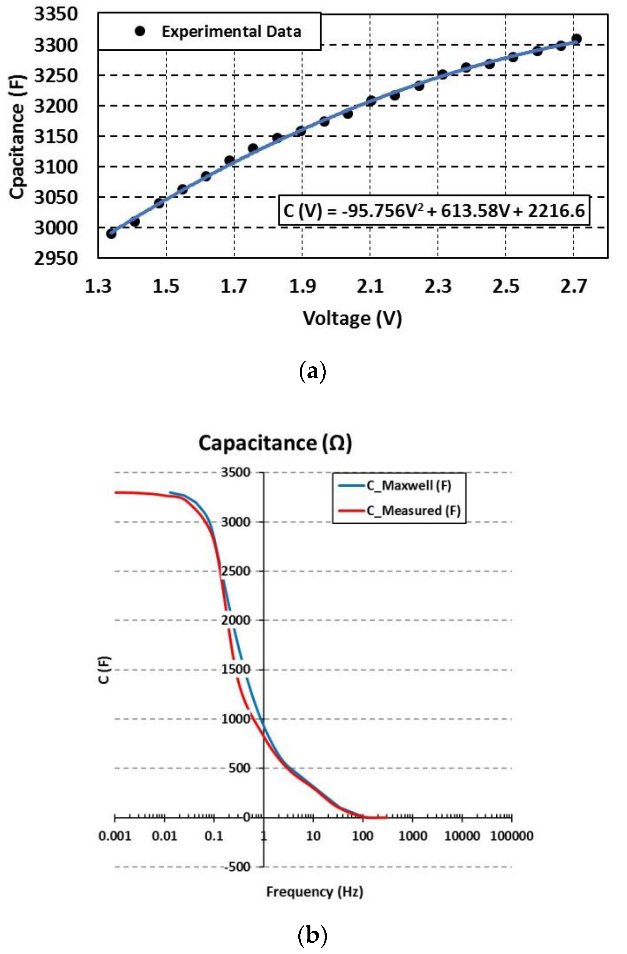
  • The first and main feature is the capacitance. This parameter represents the energy storage behavior of the SCs, being a function of the voltage and the frequency [12]. This variation, shown in Figure 2a, is between 15% and 20% of the rated capacity [13]. This effect is important in ESS applications since the ESS operating voltage impose a capacitance value different to its rated value, which provokes less stored energy. Moreover, the operation frequency of the SCs modifies the capacitance value. Figure 2b shows that there is a cut-off frequency, usually around 1 Hz depending on the materials and manufacturing processes, where the rated capacitance drastically decreases. Therefore, SCs are usually considered for fast charge–discharge cycles, from tens of seconds to minutes.
  • The second effect is the inner resistance. Joule effect takes place in the positive and negative current collectors, the positive and negative porous electrodes and in the separator [12]. Due to the electron transportation process, their kinetic energy is converted into heat. These effects on the conductors and the electrolyte are grouped in a single term named ohmic phenomena and represented by the equivalent series resistance (ESR). The ESR is not constant and depends on the frequency and the cell temperature in a non-linear form [14], as shown in Figure 3. The ESR value is reltively low compared to other electrochemical ESS such as batteries. However, attention should be paid to the ohmic losses on the SCs in those applications which require high power [15]. Moreover, ESR provokes a voltage drop, decreasing the SCs efficiency, and a temperature rise inside the cells. This heat produced from losses needs to be evacuated in order to avoid accelerated aging due to overtemperature. Therefore, proper operation of cooling systems is always required.
  • The third parameter in a SC is the self-discharge, which is a drawback of using SCs for cycles longer in the order of hours [16]. The origin of this effect is the redox reactions at the electrode surface when the electrons cross the double layer [17]. This parameter depends mainly on voltage, temperature and aging. Therefore, it could be modelled as a voltage-controlled temperature-dependent current source. The self-discharge current value is given by the manufacturer in the datasheet as a constant value [16].
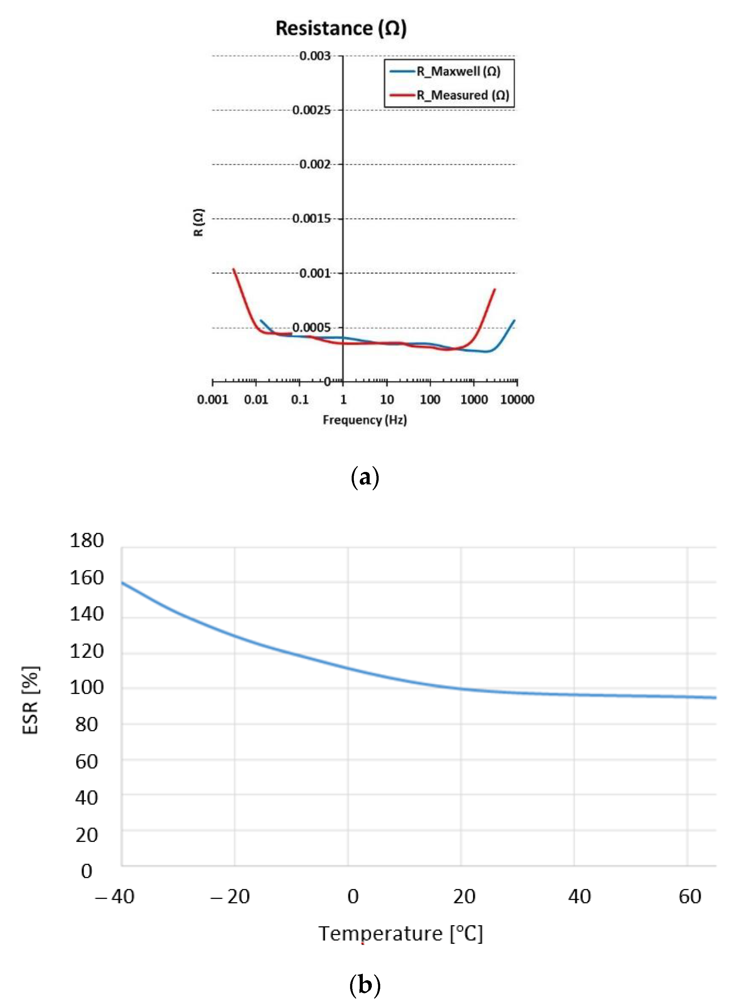
Figure 3. (a) ESR variation respect to the voltage, adapted from [7]; (b) ESR variation as a function of the frequency.
Energies 14 03060 g003
Navarro G. [18] presents a study in which all these parameters are analyzed and aging and voltage imbalance in a large series connection of SCs are calibrated. Table 4 collects the main parameters of commercial cells for several manufacturers.
With respect to the lifespan of the SCs, several limits are established that imply the SCs replacement. A SC cell is considered to have achieved the end of its useful life when any of the following point are fulfilled:
  • ESR current value has doubled from its initial value.
  • The current capacitance value has decreased by 20% compared to its nominal value.
  • The SC operating cycle number is more than 1 million.
Finally, the last step in the designing and dimensioning process is to evaluate the system losses. A SC-based ESS comprises the SC cells and an interface DC/DC power converter. Power losses take place in both devices, imposing the following issues [15]:
  • The ohmic losses in the system located in the SCs, represented by the ESR value, the cell-bars which connects the SCs and the power cables.
  • The cooling system to maintain the SCs in an optimum operating temperature range.
  • The power electronics (conduction and conmutation) losses.
Considering a literature review, there are many articles focusing on organizing and summarizing the new published research advances of this type of technology, as collected in [26]. This paper collects both small- and large-scale applications. For this purpose, the applications have been classified in four main groups: electric traction applications; renewable generation systems; microgrid and power grid connection applications; and autonomous power systems for energy distribution and ships and aircraft applications.
Figure 4 shows the percentage of scientific publications in the last five years related to SCs for the four application groups:
  • The most published topic is related to the use of SCs in electric traction applications. This group represents 50% of the published studies. Most of them related to electric vehicles (EV) or hybrid electric vehicles (HEV).
  • The second group of the most published topics is related to power grid applications. Most of them are related to the improvement of the control strategy of a microgrid, the voltage and frequency regulation, and the increase of the battery lifespan.
  • The third position is for the group of studes related to the renewable generation systems, especially solar PV, wind and wave energy sources. Finally, the last group with 10% of the papers are those applications related to the autonomous power systems, ships and aircrafts.
This paper describes the most important studies done for the three main groups which represent most of the SCs present applications. Those groups collect almost 90% of the whole researches related to SCs.
The information is structured into the following sections. Following this introduction, in Section 2 the applications related to the electric traction are described. This section collects both the railway and the road vehicles. This is followed in Section 3, describing in detail the applications related to the renewable generation systems, which include solar, wind, wave energy and hybrid generation systems. In Section 4, those studies that analyze the electrical systems connected to the grid are detailed; within them, there are topics as frequency regulation, voltage drop problems, etc. Furthermore, this group includes those researches related to microgrids. Finally, the paper concludes with Section 5, which contains a summary of the most important aspects covered, as well as the future prospects of the technology based on the information provided for different applications.

2. Electric Traction Applications

The electric traction drives can be applied to diverse means of transport that use the road or rail transport modes. Regarding the road mode, SCs might be applied in:
  • Means of public transport power by catenary
  • Hybrid electric vehicles
  • Pure electric vehicles
On the other hand, within the vehicles that move on rails, it is possible to distinguish between:
  • Heavy-rail catenary supplied vehicles
  • Heavy-rail diesel–electric vehicles
  • Light-rail rapid transit vehicles
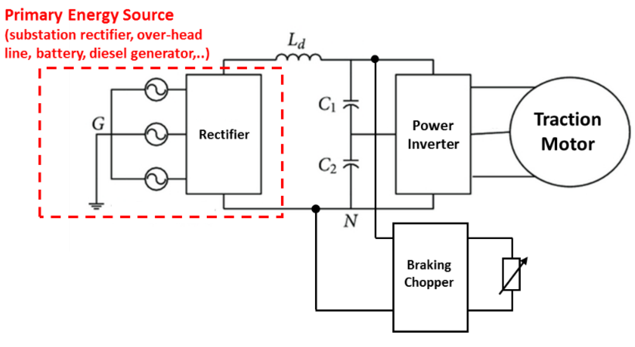
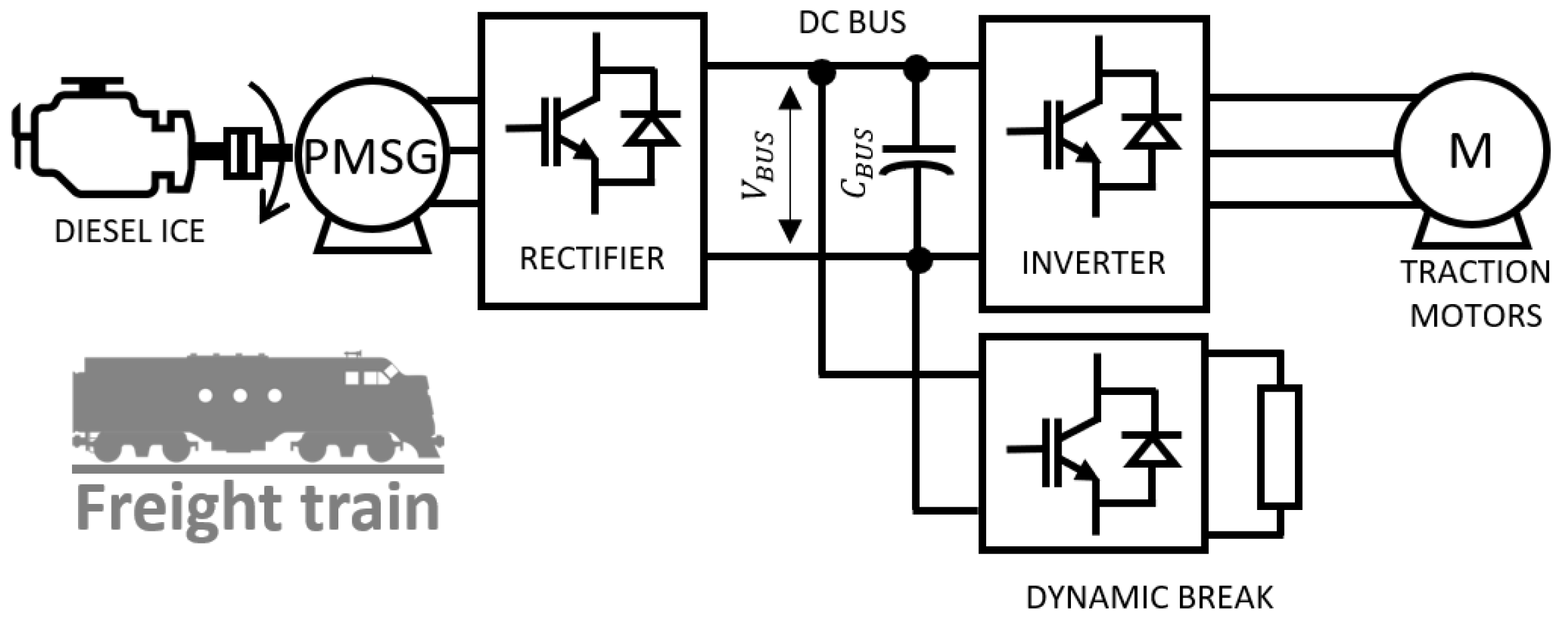
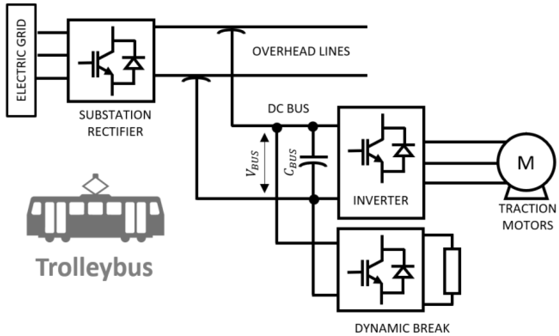
Whether they are vehicles that move on rails or on the road, they have a common structure: a traction drive and control system. Its power stage is formed by the traction motor, the power electronic converter, a braking chopper or dynamic brake and a high impedance/ high power density power supply. This power supply has the capacity to absorb high power consumption peaks, while the power inverter drives the traction motor, and the braking chopper limits the DC voltage during braking dissipating the excess energy into a resistor. Figure 5 shows a general electric scheme of the traction system for this type of vehicles.
Regarding the stages in which the route of a vehicle can usually be divided, the followings are distinguished:
I.
Acceleration section (beginning of the route): During this acceleration stage, the vehicle goes from zero speed to nominal speed. Moreover, during this phase, the power consumed begins to increase until it reaches its maximum value when the vehicle reaches its nominal speed.
II.
Nominal or cruising speed: At this stage, the power drops till a minimum value required to maintain the vehicle speed at its nominal value.
III.
Braking or deceleration phase (end of route): During deceleration, the kinetic energy of the vehicle is transformed into electrical energy by means of a regenerative braking.
As a consequence, the power fluctuations are very high: positive, minimum and finally negative. The problems in the power system derived from this highly irregular power profile are:
  • Fluctuations in the supply voltage and instability [27].
  • Higher losses in the power system.
  • Significant energy consumption due to not being able to take advantage of the braking energy: not reversible power supplies and braking chopper.
  • Oversized power system due to the need to fully supply the energy consumed by the vehicle.
A possible solution to the aforementioned problem is the inclusion of a storage system in the vehicle’s power train to supply/absorb high power peaks for short periods (acceleration and deceleration section) and to recover braking energy by eliminating or reducing considerably the size of the chopper. When sizing the storage system, it is required to define the maximum power peaks (positive and negative) and the stored energy level. In general, those vehicles use other main power systems and the storage system would usually operate for periods of less than 1 min. Considering the particular characteristics of SCs (high power density and low energy density), they are a highly recommended option for this type of application.

2.1. Electric Drive for Rail Vehicles

2.1.1. Heavy-Rail Catenary Supplied Vehicles

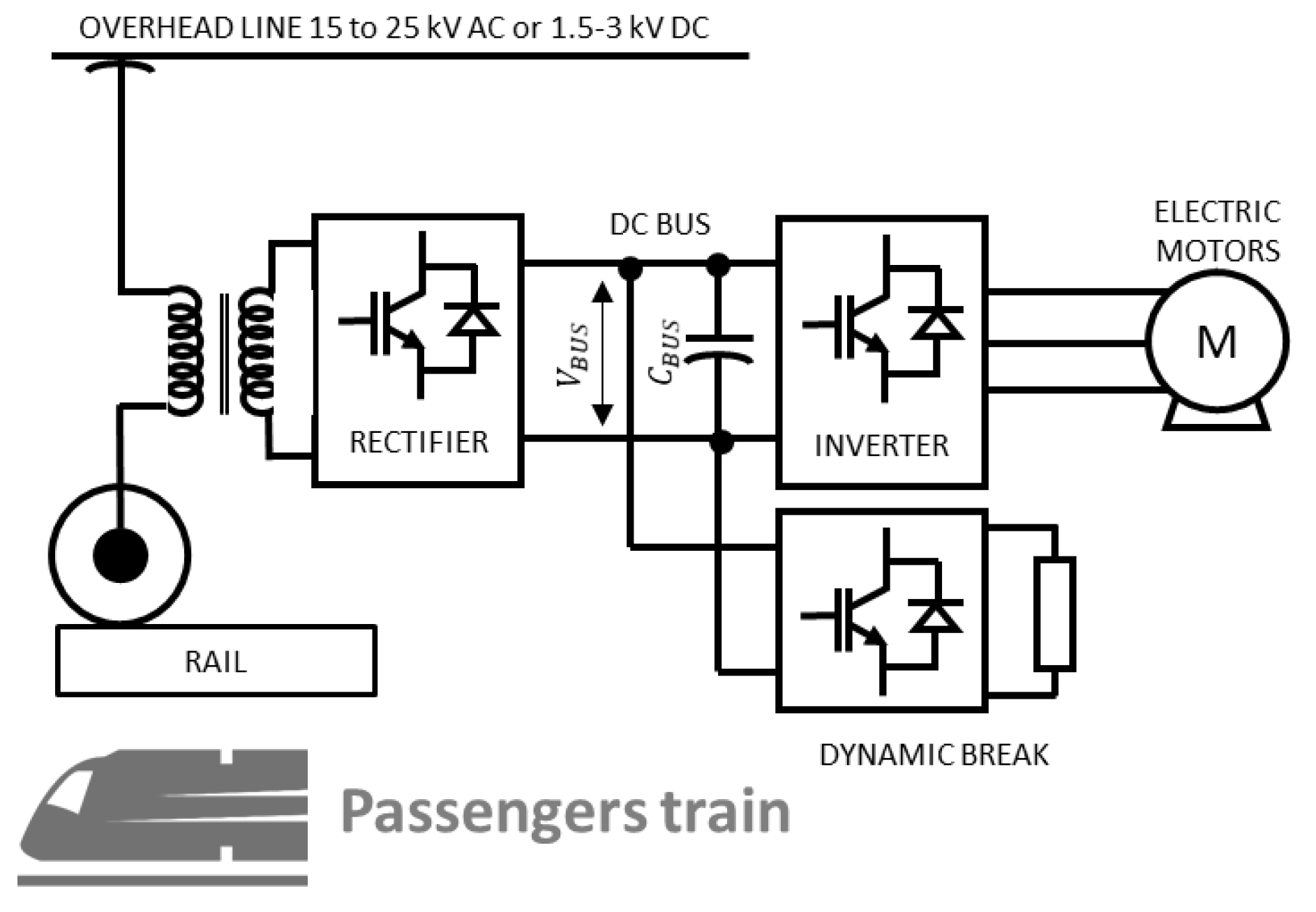
This category mainly includes transport locomotives such as high-speed short-distance passenger and freight trains [28]. In general, the traction system of these vehicles is fed from an overhead line (primary power supply) through a pantograph. The voltage level varies depending on the country, generally 1.5–3 kV DC (short-haul train) or single phase 25–50 Hz (short and long-distance trains). Figure 6 shows a typical block diagram of a common heavy-rail catenary supplied traction drive without any ESS.
There are several researchers that describe the use of SCs in this type of vehicle. Dutta, O. [29] proposed a mathematical optimization methodology and a model of a stationary storage systemfor a DC rail transportation application, New York City Transit (NYCT). In this study different technologies are compared, including batteries, flywheels and SCs working independently or together. The results of the optimization process are based on the percentage of energy savings because of regenerative braking, voltage regulation, reduction in peak demand, estimated payback period and system re-siliency. The paper concludes that the cheapest storage system to operate autonomously are SCs. On the other hand, it highlights that regarding the the resilience of the system, a hybrid system made up of batteries and SCs is the economic option as long as the percentage of regenerative braking energy recovery is greater than 30%.
Khodaparastan, M. [30] compares two storage technologies (SCs and high-speed flywheels), from an economic point of view, to take advantage of the braking energy of a continuously powered train (650 V rectified voltage from the utility grid AC 13 kV). Two case studies are presented depending on the objective to be achieved: reduce the demand peak or stabilize the supply voltage. A cost analysis of both technologies is also performed for both purposes. It is concluded that the flywheel is the most suitable technology from the economical point of view. However, due to their technical characteristics, both technologies are appropriate for the purpose described.
Chen, J. [31] also proposedthe use of SCs to take advantage of the regenerative braking of a high-speed railway powered by a 27 kV AC catenary. The storage system is connected through a bidirectional DC/DC converter to the intermediate DC stage of a back-to-back converter, whose input and output are connected to two different points on the main power line of the trains. A state machine logic is proposed with four states (charge, discharge, transfer and standby mode) and transitions between them depending on the power line charge level and the maximum state of charge (SoC) of the ESS. One of the back-to-back converters acts as the master converter and the other converter and the DC/DC of the SCs act as slaves. The proposed control coordinates the operation of several converters to stabilize the DC bus voltage, improve the power supplyquality in high-speed railways and take advantage of braking energy. The cost savings will depend on the policy of power utility companies for the returned regenerative braking energy.
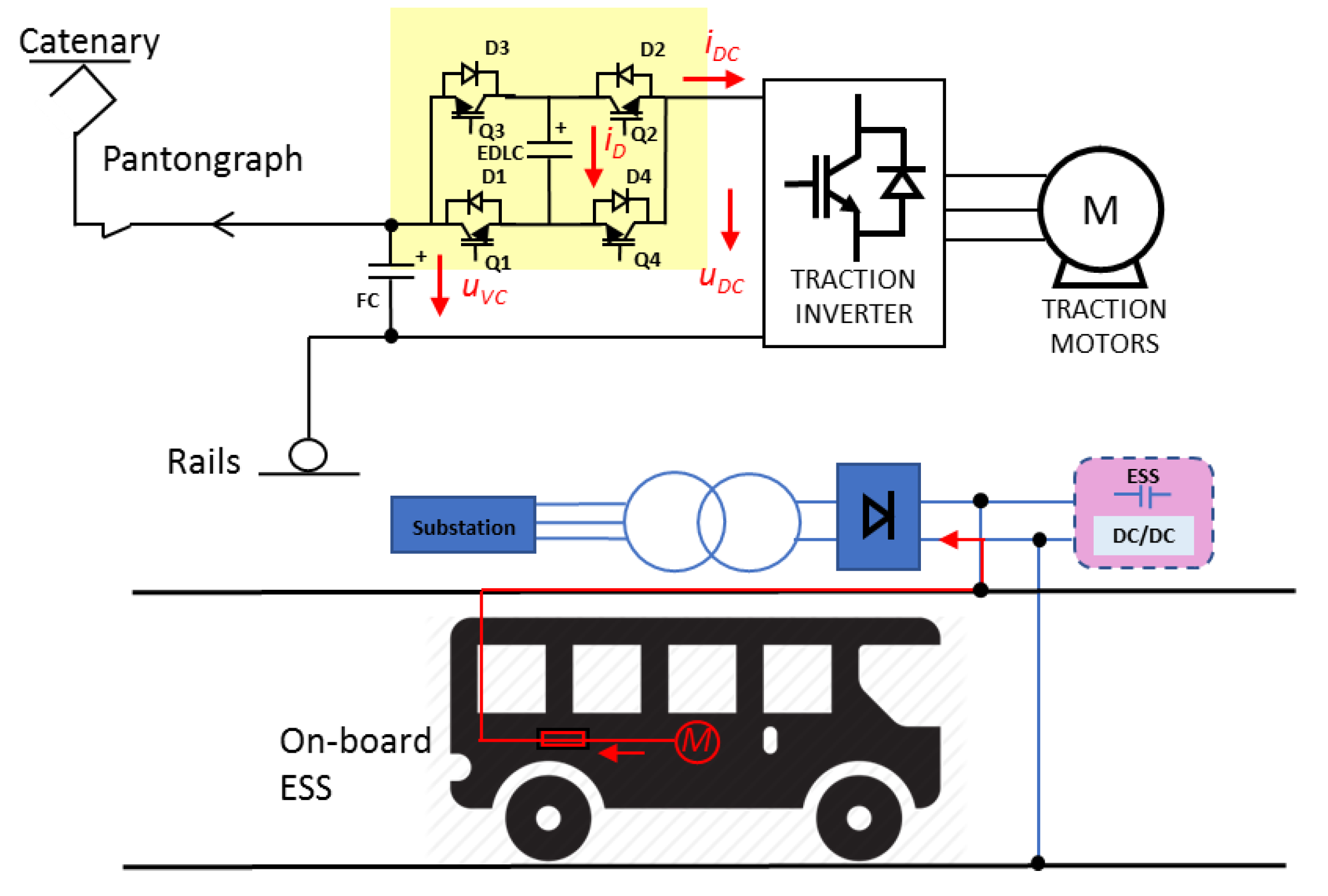
Zhong, Z. [32] proposes SCs as an on-board storage system to absorb braking energy and completely replace the brake resitor (see Figure 7). Despite the weight that this implies, it is justified that the storage system is on board and not stationary in order to take advantage of the whole braking energy and to be able to completely replace the on-board brake resistor. A hierarchical optimization energy management strategy is proposed based on an additional power stage in series, connected between the inverter of the traction motor and the main supply voltage (DC). The storage system would be connected to the DC stage through a bidirectional converter. The three benefits extracted from this configuration are:
  • The voltage level of the DC stage is adjusted to its optimal value to extract the maximum torque for each speed.
  • The use of braking energy in any operational scenario.
  • A 10% reduction in system losses is achieved by adjusting the SCs duty cycle in real time.
Xu, C. [33] presented a study related to the use of SCs to extend the service life of the pantographs that feed high-speed trains. The arcing phenomenon due to the irregular movements of the trains and the intermittent line pantograph disconnection reduces its useful life. Morreover, it can even damage onboard equipment and measuring elements. In this study, the SCs based ESS absorbs the inductive energy and reduces the surges in the power line. The strategy to manage the system energy between the storage system, the train and the main power system is analyzed and validated by simulations to compensate the voltage fluctuations and take advantage of braking energy.

2.1.2. Heavy-Rail Diesel–Electric Vehicles

This section analyzes the applications of SCs in Heavy-Rail Diesel—Electric Vehicles. These types of vehicles run on fossil fuel and are commonly used in North America and some European countries [34]. The traction scheme of this type of vehicle is composed of an internal combustion engine (ICE) group (gas engine, petrol engine, diesel engine, or gas turbines) coupled to an electric generator that, through two power converters, feed the traction motors. They have also an energy dissipation system to evacuate the braking energy (DC chopper). A typical electrical diagram of this type of vehicle without any ESS is shown Figure 8.
Da Silva Moraes, C.G. [35] proposed a hybrid storage system (lithium-ion batteries and SCs) whereby a percentage of the braking energy is used to power auxiliary equipment, while the ICE group remains the main power supply for the traction motor. Thids would reduce the cost and volume of the diesel group. SCs are used as buffers to absorb rapid power fluctuations in a multiport configuration in which each storage system consists of a DC/DC converter.

2.1.3. Light-Rail Rapid Transit Vehicles

Light vehicles powered by a catenary constitute a type of transport that is normally used for moving passengers in urban environment [36]. The locomotive or towing vehicle is powered by an overhead line through a pantograph. The catenary in turn is fed by a power supply substation. The supply voltage level varies from one country to another, stablishing in most of them in the range of 1.5 kV or 3 kV. Figure 9 shows the most common electrical scheme used by this type of vehicle without any ESS. A three-phase inverter is usually used to power the traction motors from the catenary. On the other hand, it also has a DC/DC converter (DC chopper) to evacuate the braking energy.
In the literature, there are several papers that study the SCs introduction in the feeding scheme of this type of vehicle. Zhang, X. [37] studied the existing problem arises due to the overcurrents suffered by the SCs that feed some light urban transport vehicles during charging from the catenary. This problem is more serious when, due to power needs, it is necessary to connect several chargers in parallel. These overcurrents also cause accelerated aging of the SCs. The authors propose a protocol to coordinate the load of the different storage systems to reduce the current overshoot without hardly increasing the load time.
The study proposed in [38] shows a power management control of wayside lithium-ion capacitor to improve the efficiency of a light railway vehicle. The particularity of this paper is it concludes the SC technology that best suits the present application are Li-ion capacitor and not EDLC due to its higher energy density. The energy stored during regenerative braking is used again during the acceleration section. The energy management strategy is based on monitoring the SCs SoC and the current vehicle speed. Other important conclusions drawn from the study are that the peak power of the power supply is reduced by up to 46% and the maximum energy saved represents 30% of the energy consumed by a system without an ESS.
Zhu, F. [39] suggests a hierarchical control of a stationary supercapacitor-based energy storage system to save energy by taking advantage of braking power. The main power supply for the vehicle is a 750 V or 1500 V voltage catenary. The ESS is connected to this DC bus through a DC/DC converter. A real case study is described and analyzed in which the proposed control strategy is applied with a maximum energy saving of 12%.
Additionally, although no references related to real applications have been found, it is worth mentioning the possibility to use energy storage for ultrafast rail vehicles, mag-netic levitated trains, and the hyperloop, resulting in an especially convenient option in the second one, since the use of a power supply just for the acceleration leads to the use of short-term energy storage [40].

2.2. Electric Drive for Road Vehicles

2.2.1. Public Transportation Catenary-Supplied Vehicles

This section describes the applications of SCs in urban passenger transport vehicles powered by a catenary. This type of vehicle is usually known by the name of trolleybus [41]. The difference respect to light vehicles is the electrical circuit is not closed by the rail, but the catenary must consist of two poles. The predominant electrical scheme of this type of vehicle is shown in Figure 10. The catenary voltage is usually a direct voltage of 600–900 VDC generated from a three-phase rectifier connected to an electrical substation. The equipment on board the vehicle is made up of the inverter that feeds the traction motor and an electrical braking to avoid overvoltages in the power line (catenary). The trend in this type of transport is to replace the chopper with an ESS to take advantage of regenerative braking energy, save a percentage of energy, and, in a second step for the electrical power system, to place charging points in different sections of the route.
Cignini, F. [42] made a comparison of four prototypes of electric buses with an on-board storage system to fulfill certain speed requirements in a specific time. The study is carried out from the real data taken from the vehicles (energy consumption, acceleration, and maximum speed) in different scenarios. The four storage technologies being compared are a hybrid energy storage system (HESS) consisting of:
  • SCs and absorbent glass mat (AGM) lead batteries.
  • SCs and lithium-ion batteries.
  • SCs and lead-acid batteries.
  • SCs and lithium-ion iron phosphate batteries.
An economic analysis is also carried out to complement the previous comparison from a life cycle cost point of view. The paper concludes that the best option (lowest cost) is formed by SCs and lithium-ion batteries followed by option 1 (SCs/AGM batteries). On the other hand, from a technical point of view, option 2 is the best because it is the option that supports the highest charging rates.
Soltani, M. [43] proposed a HESS made up of lithium batteries and lithium-ion capacitor (LiC) as the only power source for a city bus. LiCs complement the use of batteries to extend their useful life by reducing the power peaks in the acceleration and decelaration stages, supplying/absorbing that energy in the LiCs. This study proposes an electrical, thermal and aging model of each ESS is presented and a methodology for the distribution of power requirements. The research concludes the HESS, compared to the ESS made up only of batteries, reduces the size of the energy storage required by 30% and the cost by 16%. The reason for this development is the increase of the battery lifetime and an improvement in the dynamic response and efficiency of the system.

2.2.2. Hybrid Electric Vehicles (HEVs)

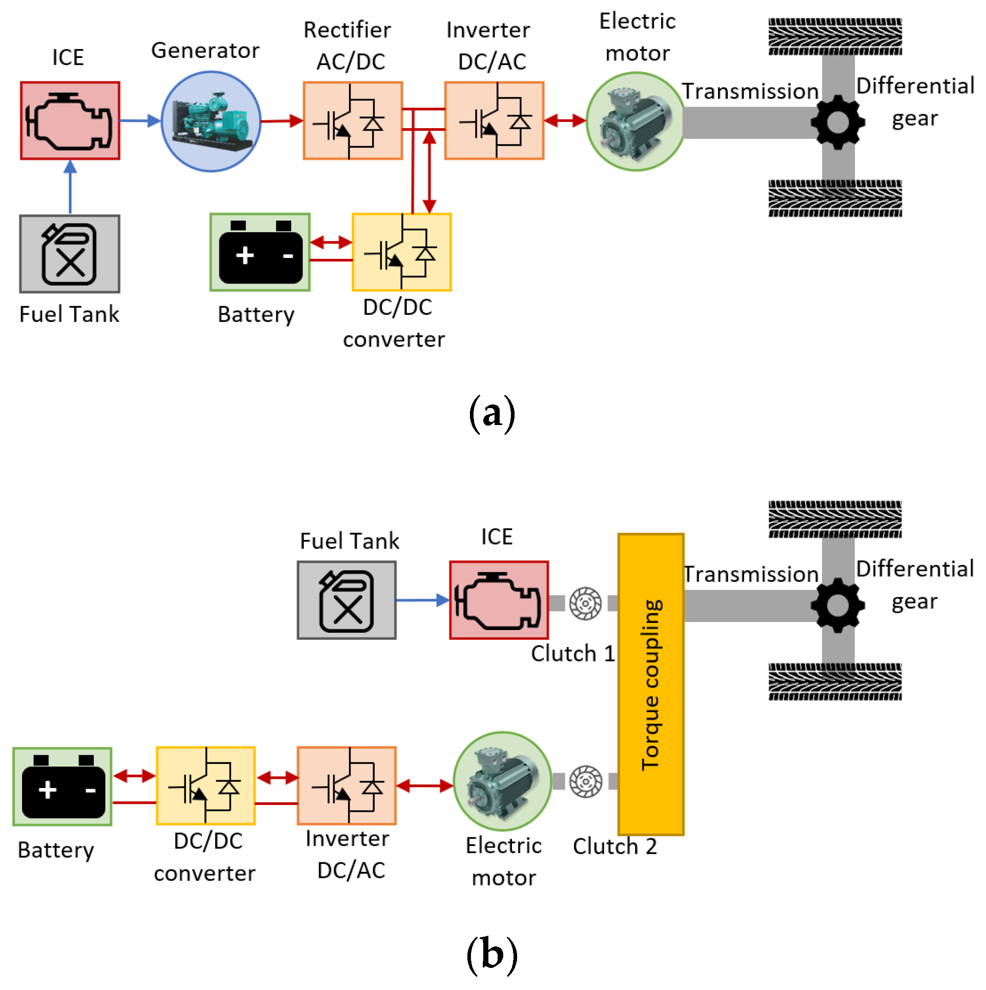
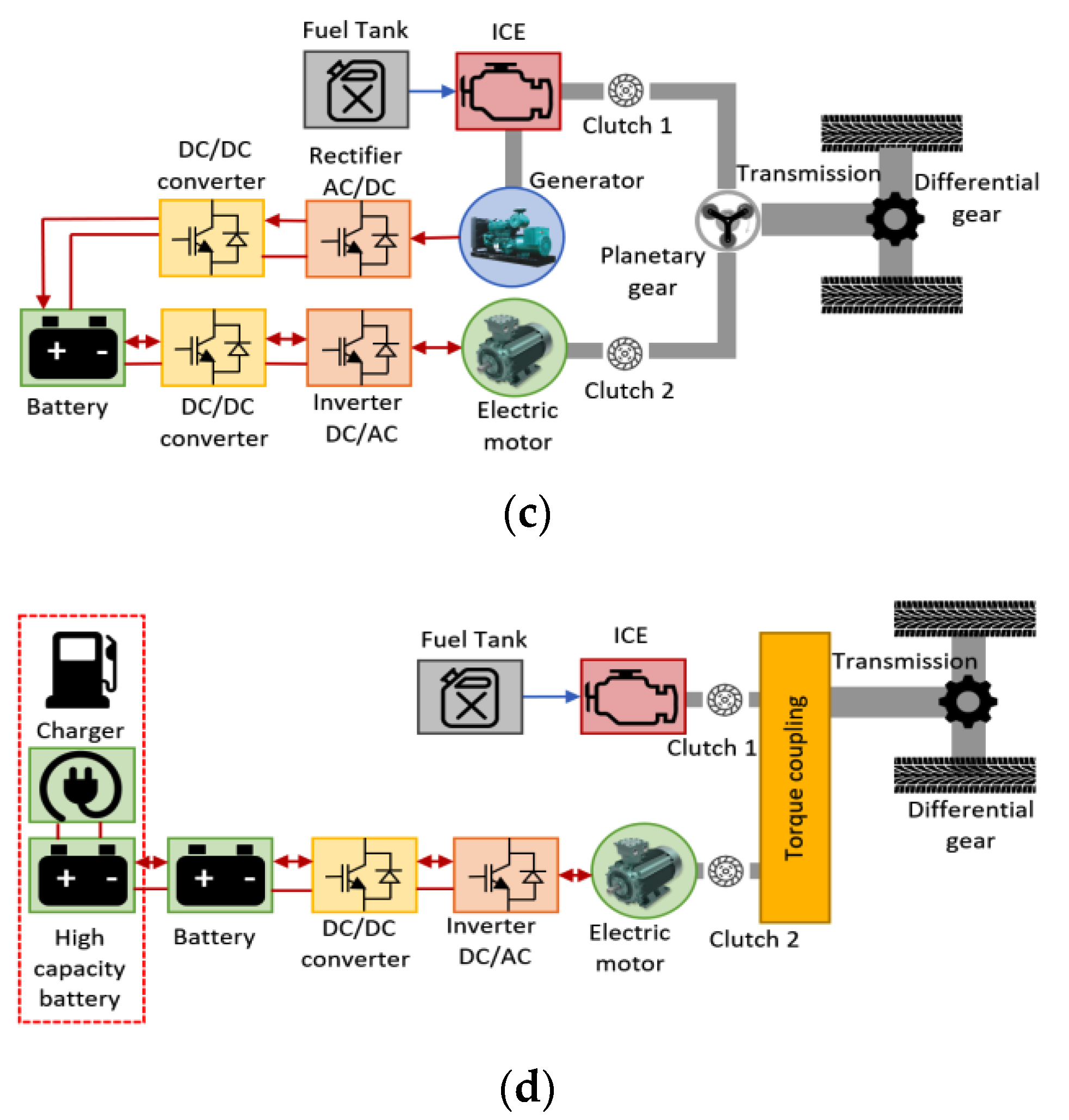
SCs also have application in hybrid electric vehicles. This type of vehicle combines an ICE group and an electric drive. The aim of the electrical system is to operate at the point of maximum efficiency of the motor at each situation. The main elements are a fossil combustion engine, an electric traction machine (generally a permanent magnet machine), a power converter and an ESS. According to the arrangement of these elements, four different configurations are distinguished: (1) series based on ICE, (2) parallel based on ICE, (3) series-parallel based on ICE, and (4) plug-in based on ICE.
In the series configuration the heat engine and the electric drive share the traction shaft (see Figure 11a). In the parallel configuration, the thermal motor and the electric drive are connected through a transmission element (see Figure 11b). In ICE based on series-parallel, the hybrid double conversion, the heat engine and the electric drive are interconnected through an electrical link as shown in Figure 11c. The ICE-based plug-in has the same characteristics as the parallel-based ICE, but it allows one to recharge the battery with an external charger (see Figure 11d).
In the literature, there are several studies which propose to include SCs in HEVs to improve their efficiency and reduce the cost of their powertrain. Passalacqua, M. [45] describes the future possible advantages of a serial versus parallel architecture due to the development of the technology of the power elements (power electronics and ESS) that make up the powertrain of a medium size HEV. An SC-based ESS is proposed as a storage system. Results obtained in simulations are presented where fuel consumption is shown for different speed profiles (road missions) and serial vehicle configurations. The vehicle studied is based is equipped with a diesel engine, SiC power converters and SCs in series configuration. The paper concludes that the serial configuration and the proposed energy management system (EMS) achieve an energy saving of 35–48% compared to conventional configurations.
Passalacqua, M. [46] also described and analysed how the sizing of SCs affects engine number of starts (comfort) and the amount of energy that can be stored during braking. A review of the characteristics of a series configuration in HEVs is made and SCs are studied as the only storage system to make series configuration more efficient compared to the parallel configuration in a HEV. An EMS and seven experimentally measured road missions are proposed to calculate the required energy from the ESS to recover all the braking energy. From the point of view of the need for storage energy, mountain mission is the most demanding. The energy needs for the road missions studied are 150–200 Wh with an approximate weight of 40–50 kg. It is suggested that, if LiCs are used instead of EDLC technology, the storage weight would be reduced to 25–35 kg.

2.2.3. Electric Vehicles (EV)

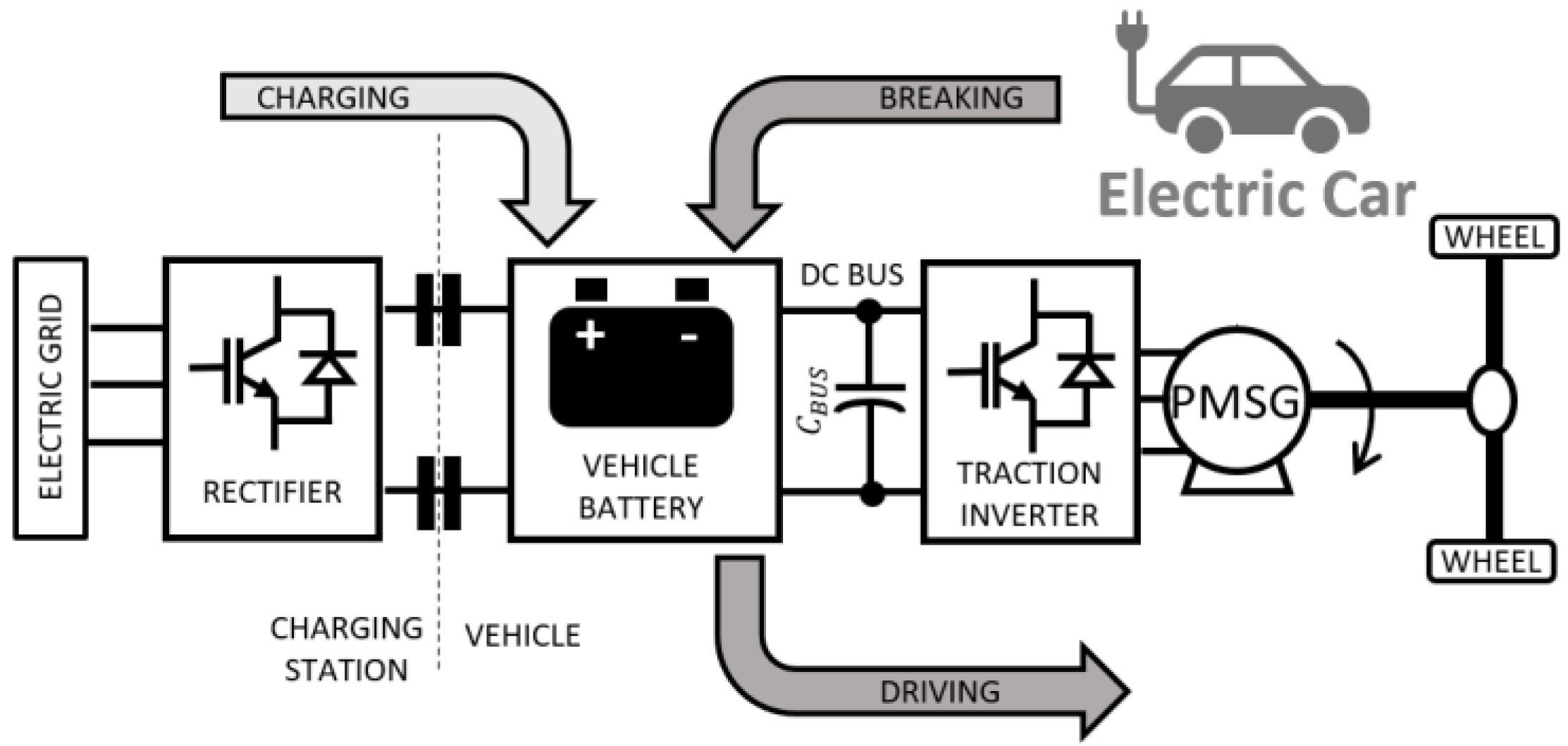
EVs are vehicles with a pure electric powertrain, i.e., without another power source of a nature other than electric [47]. Figure 12 shows an overall diagram of the traction system in this type of vehicle. In general, the parts that make up the electric drive of an EV are: an ESS (electrochemical battery, fuel cell), a power converter, and an electric traction drive. Depending on the ESS, a braking resistor is necessary (e.g., fuel cells as power source) or not (battery) to dissipate the braking energy.
As in the previous sections, there are studies which analyse the inclusion of SCs in the electric drive of an EV to improve its dynamic response and reduce the cost of the ESS because of the higher battery lifetime. One of these studies is [48], in which a HESS made up of batteries and SCs is analyzed to be used in EVs. Two options of EMSs are proposed, one based on a low pass filter with a fuzzy logic controller and another based on an adaptive proportional integrator. This control distributes the power supplied between the battery and the SCs during acceleration and stores the energy during braking in the SCs considering their SoC. A simulation study has been done for different drive cycles (New York City cycle, Artemis urban cycle, and New York composite cycle). The conclusions of the paper are as follows. The proposed control strategy allows to reduce the variation of the voltage, higher SoC of the battery and efficiency, lower losses in the battery, a reduction of the current ripple through the battery, and a slight increase in temperature. In this case, no economic analysis is performed to compare this configuration to one that uses only batteries.
Sadeq, T. [49] also proposed an EMS for a HESS (battery/SC) to improve the dynamic response of EVs. The proposed topology is a battery/SCs system in semiactive configuration [50]. In order to distribute the power delivered by each ESS, two adaptive algorithms (optimal adaptive and fuzzy adaptive controller) are compared taking into account the profile traveled by the vehicle. Three profiles are simulated in MATLAB-Simulink at three different speeds, demonstrating that the useful life of the batteries is increased due to the reduction of the stress on the battery during high load operations. On the other hand, it is concluded that the response of the vehicle with an optimal adaptive controller is better than with a fuzzy adaptive controller in most cycles.
Additionally, the research described in [51] proposes a traditional topology of a HESS (battery/SC) to improve the drawbacks of using a ESS made up only of batteries (high cost, low power density and short cycle life). For the sizing of the ESS and the power distribution, a bilevel multiobjective design and control framework with the nondominated sorting genetic algorithm (NSGA-II) and fuzzy logic control (FLC) is described. The authors conclude that a good EMS allows reducing the dimensioning of the SCESS (size and volume), achieving the same dynamic response as with a larger mass of the HESS.
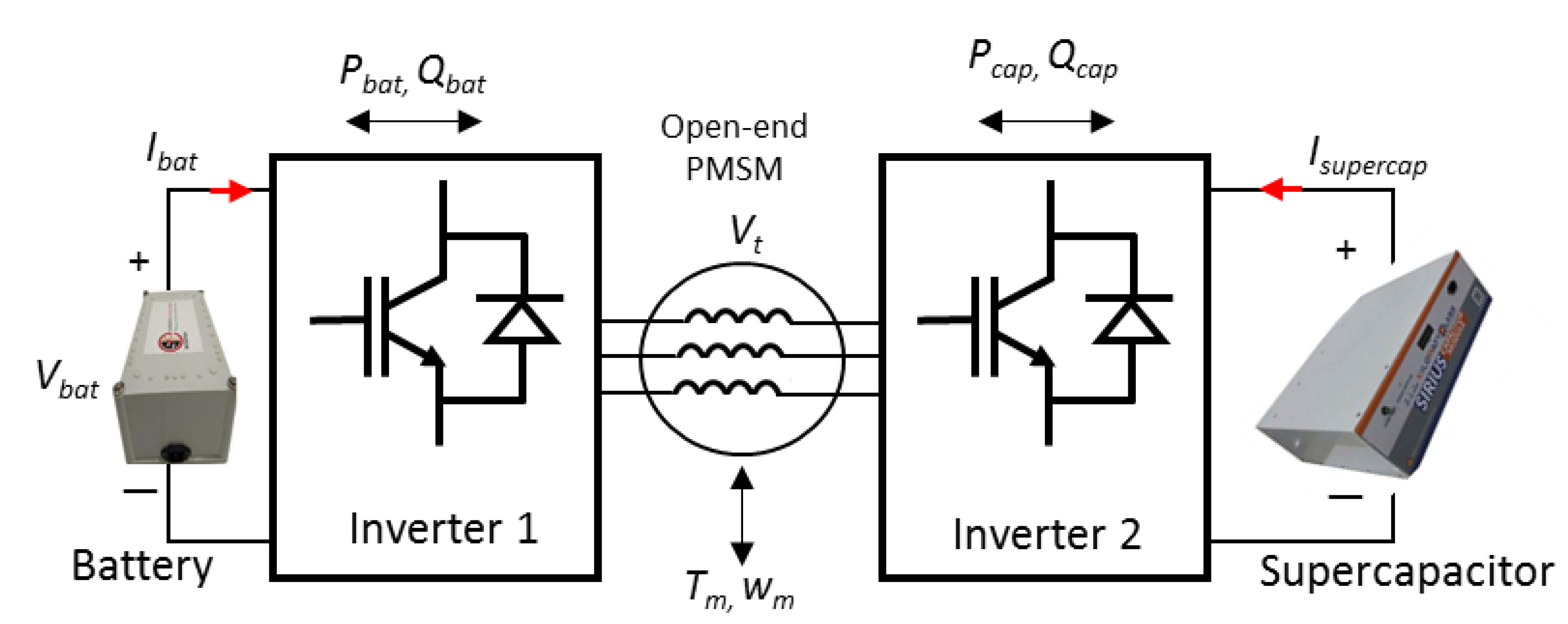
Finally, regarding the most common topologies, Shi, R. [52] proposed a new topology of a HESS comprising batteries and SCs is proposed to distribute the power needed by an open winding motor. This topology connects both ESS to the electric motor through a power converter (dual in-verter drive), which makes it easier for both the batteries and the SCs to deliver the active/reactive power requirements (see Figure 13). This allows the use of machines with a higher voltage level than those that can be used with a traditional configuration. During the periods in which the required power is low, SCs remain in stand-by to improve the efficiency of the set. Experimental tests are carried out with a 10-kW liquid-cooled EV motor.

2.2.4. Wireless Charging of EVs

This section describes the existing papers in the bibliography that propose the use of SCs in wireless power transfer (WTP) systems for EV recharging. The selected papers have been those considered most relevant in the last three years. In general, the use of an ESS, in this case SCs, is justified to reduce the high fluctuations in power consumption and allow the power flow in the charger to be bidirectional, increasing its versatility. The papers that have been considered most relevant are described below.
Lu, W. and Geng, Y. [53,54] propose the inclusion of a HESS (SCs/lithium-ion batteries) in WTP systems. Lu, W. [53] proposed a methodology for sizing the HESS for recharging a 100kW electric bus during the time the vehicle is at one of the stops on the route. The proposed methodology is applied to a laboratory prototype in which the output power is analyzed based on the power transfer distance, reaching an efficiency of 89.6%. Additionally, Geng, Y. [54] focused on the control strategy from the point of view of the efficiency and cost of the system. The proposed strategy is based on the dynamic distribution of power between both ESS to get the WPT system to work at the optimum power point throughout the entire operating range. The strategy is validated in a 27.8 kW laboratory prototype. The efficiency achieved of the WPT System is 93% with a reduction of the required power of 27.6% compared with non optimal control charging.
Azad, A. [55] proposes the use of SCs as the only ESS to dampen power grid fluctuations that occur in dynamic and wireless power transfer (DWPT) in EVs charging. It seeks to ensure the stability of the network to which the charging point is connected. A complete analysis of the system is carried out through simulation including the design of the regulator and the modeling of the converter, achieving a reduction of grid transients by 75%. Ruddell, S. [56] presents a new topology of a WTP system, also with SCs, for the dynamic recharging of EVs. Experimental tests are carried out on a 3.8 kW prototype highlighting the advantages of the proposed topology over the conventional ones due to its reduced complexity and lower number of required switches. Finally, Wu, Y. [57] also proposes SCs as an energy buffer for dynamic loading in WPT systems. The ESS stores energy when the coupling is strong and discharges when the coupling is weak. To optimize the dimensioning of the ESS (smallest capacitance) and the pole spacing between two adjacent transmission coils and capacitance of SCs (maximum distance) a genetic algorithm is used. The proposed method is verified by simulations to demonstrate that the WPT system allows for increasing the power density and reducing the construction cost compared with WPT systems without SCs.

3. Renewable Generation Applications

There are two main problems in the operation of generation plants based on renewable energy sources. The first is related to the fluctuating nature of the renewable resource and, as a consequence, the fluctuation of the electrical power generated. Power fluctuation injected into the grid can cause the variation of the point of common coupling (PPC) voltage and affect the system’s stability [58]. The second problem is related to the operation and behavior of the renewable generation system when there are disturbances at the grid point where it is connected. In general, this section describes the existing papers in the bibliography that include SCs as a possible solution to the problems discussed. This section is divided into three main points depending on the renewable resource: wind, solar energy, and wave energy.

3.1. Wind Energy

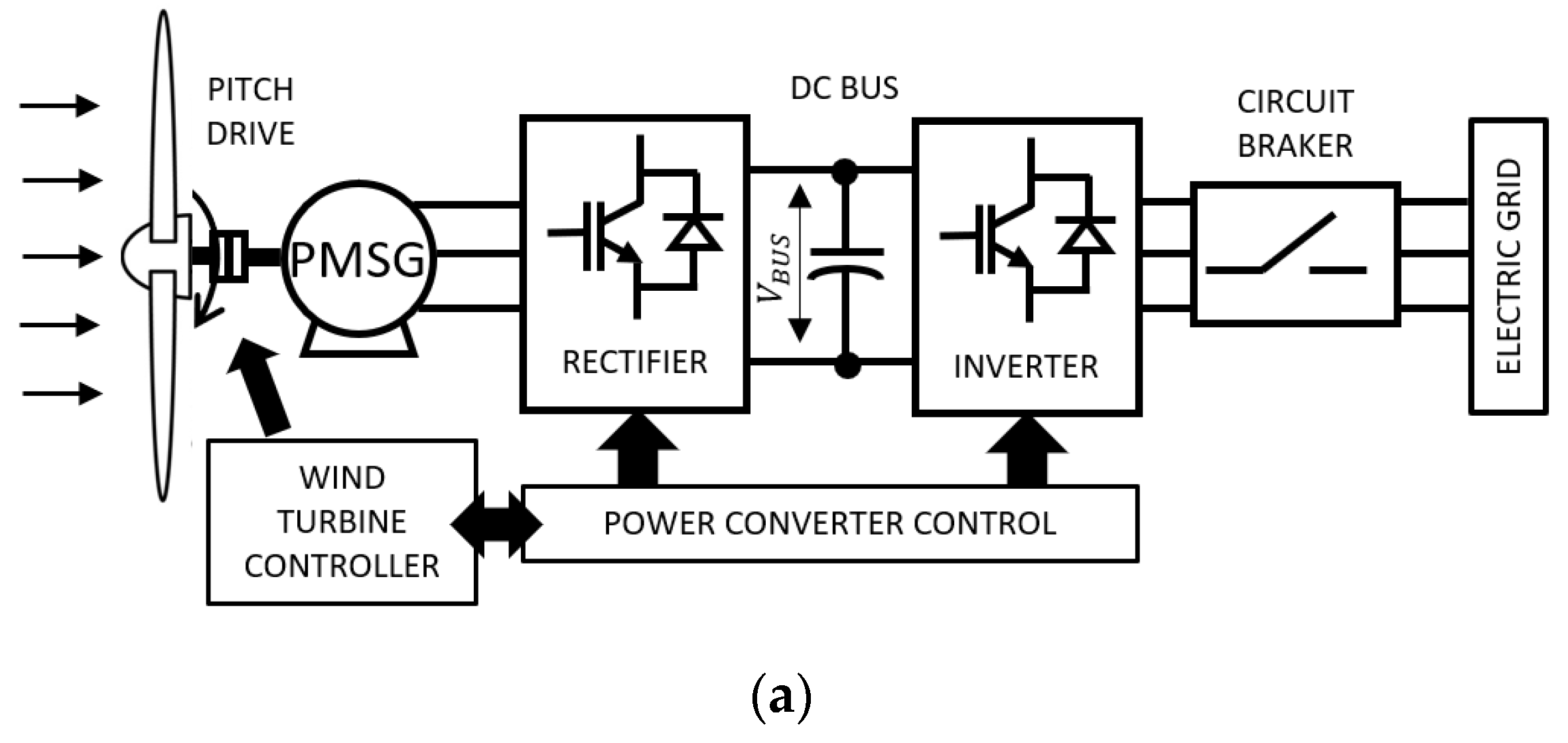
Wind energy is the renewable energy used mostly in the world. The power of wind turbines today can reach up to 3 MW. However, the power generated is highly variable as is the wind speed [59]. A generic electrical scheme used in wind turbines is shown in Figure 14a. It consists of a variable speed wind turbine, an electric generator and a double power conversion stage with two power converters. There are different variants, but normally the converter connected between the generator and the intermediate continuous stage controls the turbine pitch and the generator torque (maximun power in function of the wind speed). On the other hand, the converter connected between the continuous stage and the power grid regulates the DC bus voltage and the reactive power exchanged with the power grid. Although the variation in the power generated can be reduced, it cannot be eliminated due to the dynamic response of the pitch control, which for fast speed variations is not capable of eliminating the fluctuation reflected in the output power. Another effect to take into account is the power fluctuation as a consequence of the tower shadow effect that causes a pulse in the torque and in turn a fluctuation in the output power.
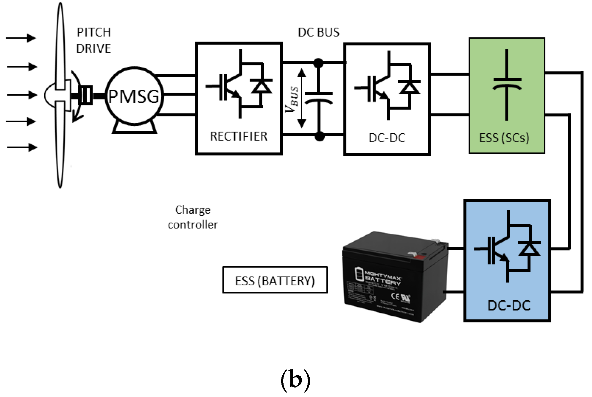
Panhwar, I.H. [60] proposed a HESS (SC/lead-acid battery) to smooth the generated wind power. The wind energy converter consists of a wind turbine mimicking converter (wind turbine generator, rectifier and DC/DC converter), a SCs module, a charge controller and a battery as shown in Figure 14b. The first DC/DC converter charges the SCs and the charge controller control is designed to charge the battery from the energy stored in the SCs. The conclusion of the paper is that the proposed configuration allows smooth charging and extended discharging of the battery. On the other hand, the topology and the proposed mode of operation causes reduced stress on the generator and ancillary components of the circuit.
Liu, J. [61] also proposed a HESS (battery/SC) to smooth out the fluctuations of wind power. The low-frequency components of the generated power are absorbed by the battery and the high-frequency components by the SCs. That makes possible to reduce the charge/discharge times of the batteries and thus extend their useful life. A control strategy is proposed in which the SoC of the storage systems is taken into account to avoid deep discharges, overloads and allow them to work at the optimum efficiency points. Experimental results are presented in which a DC/AC converter controls the HESS to achieve bidirectional active and reactive power exchange. The proposed strategy is validated, demonstrating the optimal response of the HESS to improve power quality and enhance the stability of power systems.

3.2. Solar PV Energy

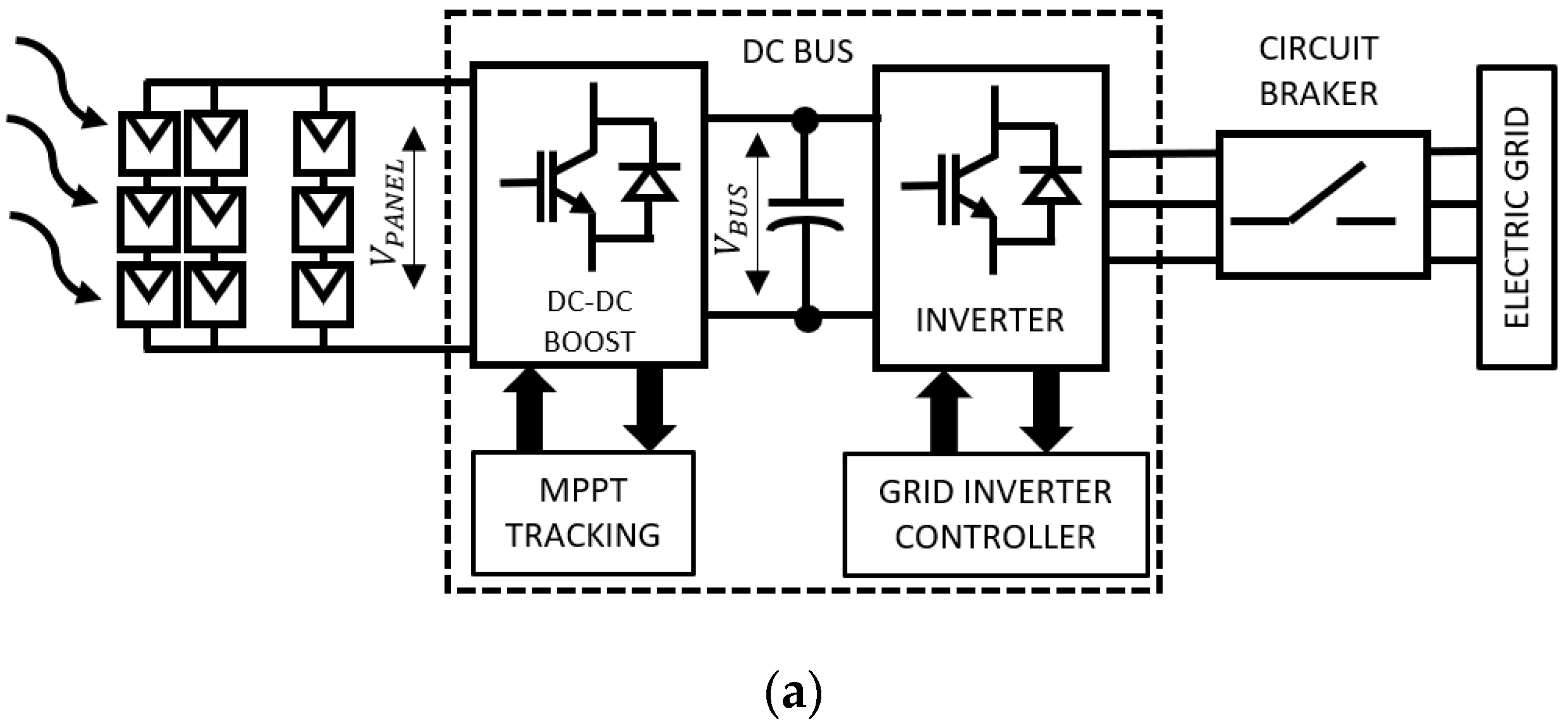
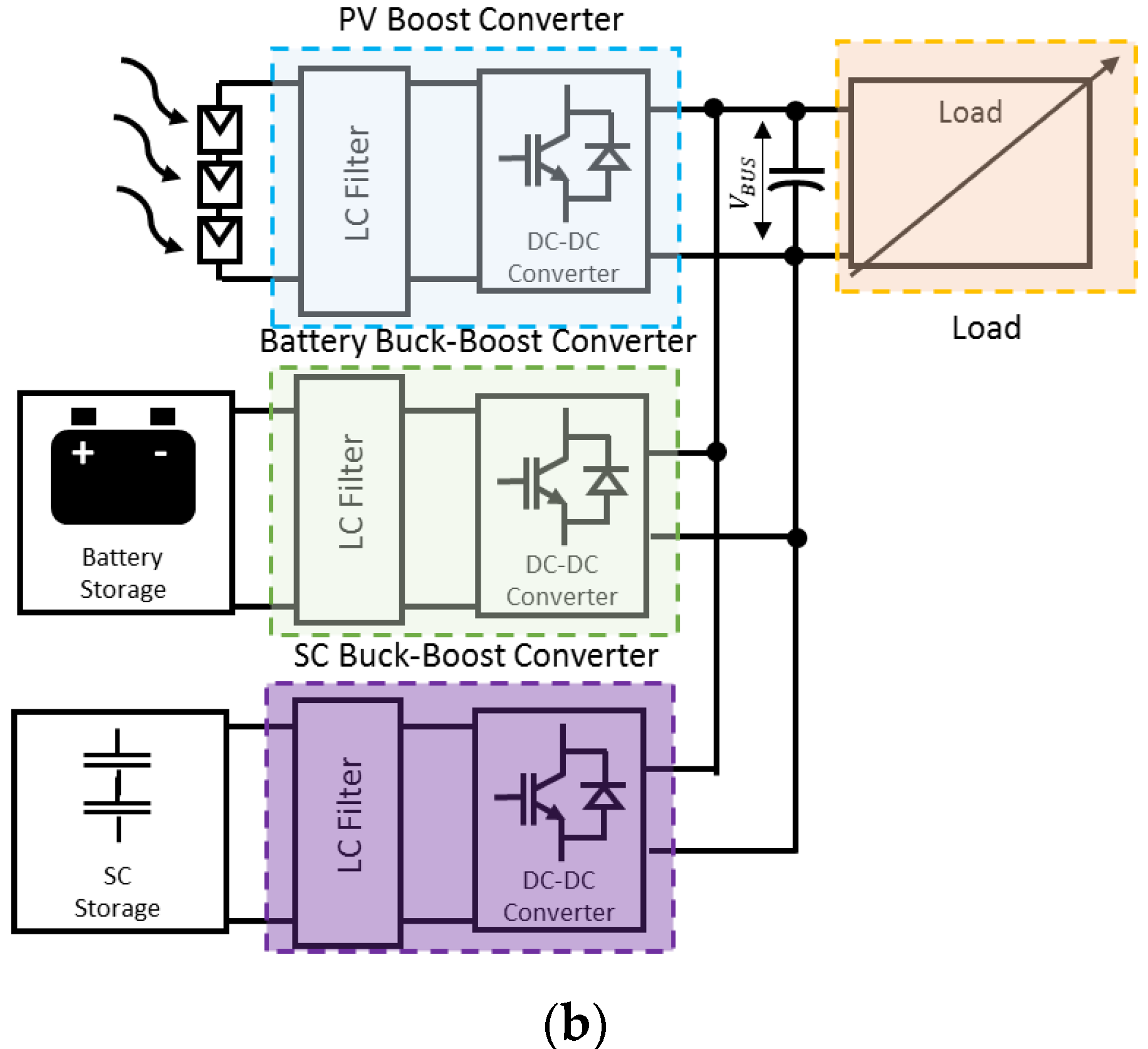
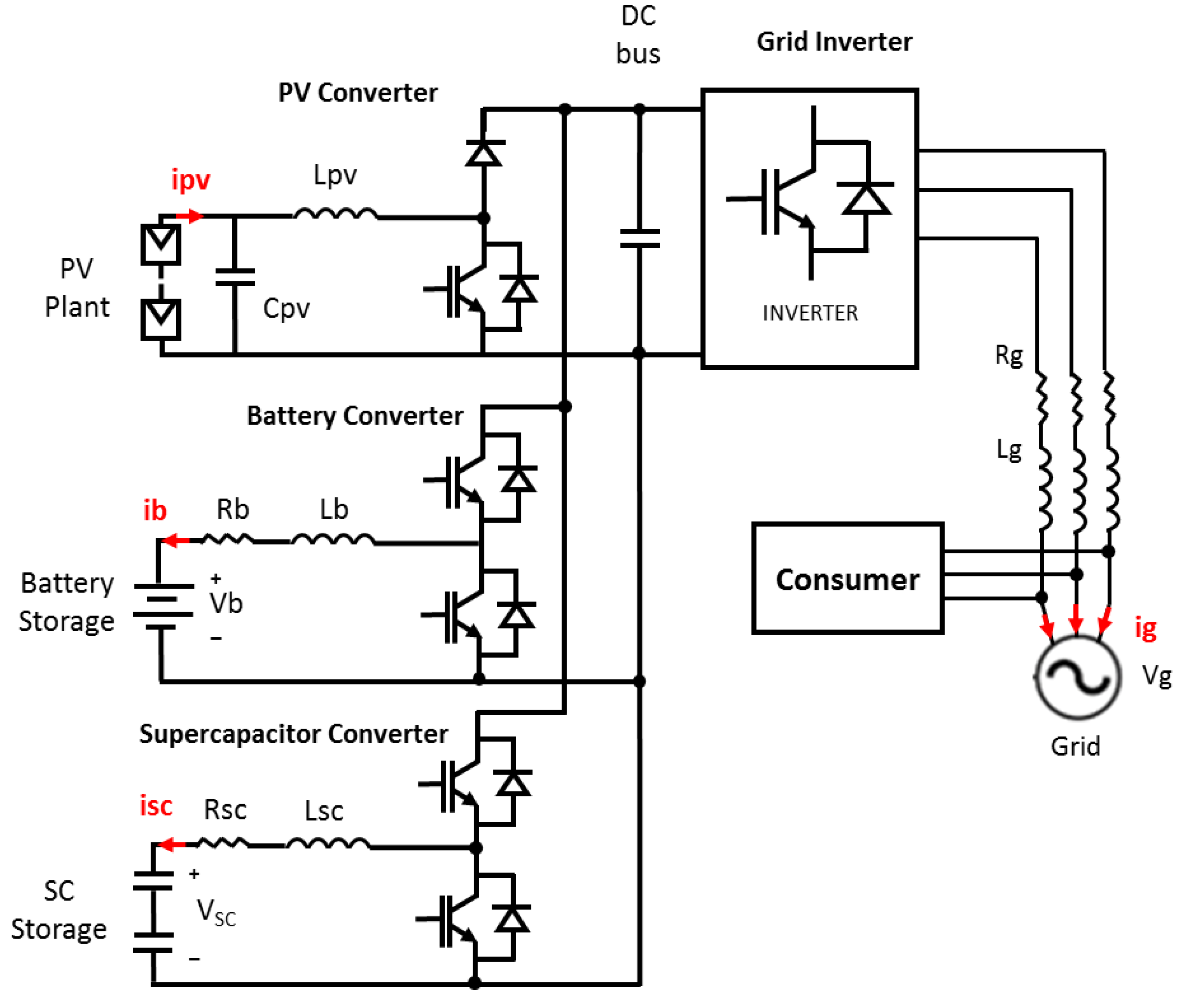
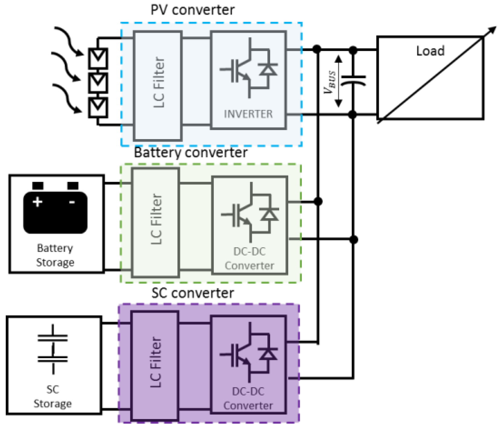
Solar Photovoltaic (PV) panels are used to convert solar energy into electrical energy. The system that extracts energy from the sun is made up of a solar panel and a power conversion stage that connects the PV panel with the load or the electrical grid. The power conversion stage (power electronic converter) can be single stage (solar PV panel connected directly to the power inverter) or double stage (solar PV panel connected to a power converter with an intermediate direct voltage stage). Figure 15a shows a possible simplified electrical diagram of a double-stage solar PV plant connected to the electrical grid. The problems associated with solar energy are the irregular generation of power, maximum in periods of highest levels of solar irradiation or unregulated in partially cloudy days.
Cabrane, Z. [63] proposed SCs to compensate voltage drops during short periods of time in soalr PV systems connected to the grid. A coordinated control algorithm is described to compensate the effects caused by the variable solar irradiance in PCC and results obtained from simulations are shown. The algorithm applies a two-stage topology with the SCESSS connected to the intermediate DC stage through a DC/DC converter.
Ma, W. [64] proposed a HESS composed of batteries and SCs to smooth out the power fluctuations of solar PV systems. A multi-objective optimization model is established to split the required power between both ESS. The variables that are taken into account in the algorithm to decide how much power each one contributes are: power losses, lifetime aging, cost of batteries and the SoC of the SCs.
Cabrane, Z. [62] proposes an EMS for a HESS (battery/SCs) applied to PV energy in order to stabilize the DC voltage. Different topologies are compared (hybrid passive parallel, semi-active, and multiple converters) for the connection of SCs and batteries in photovoltaic energy systems. The advantages and disadvantages of each of them are listed. The control proposed by the authors applies to the configuration of multiple converters. For the distribution of the necessary energy between batteries and SCs, a low pass filter is applied. Proportional integral (PI) controllers are used to regulate the DC bus voltage. The output of these regulators is the ESS charge/discharge current reference. Finally, results obtained from simulations are shown and the SoC of batteries is compared for different filter constants.

3.3. Wave Energy

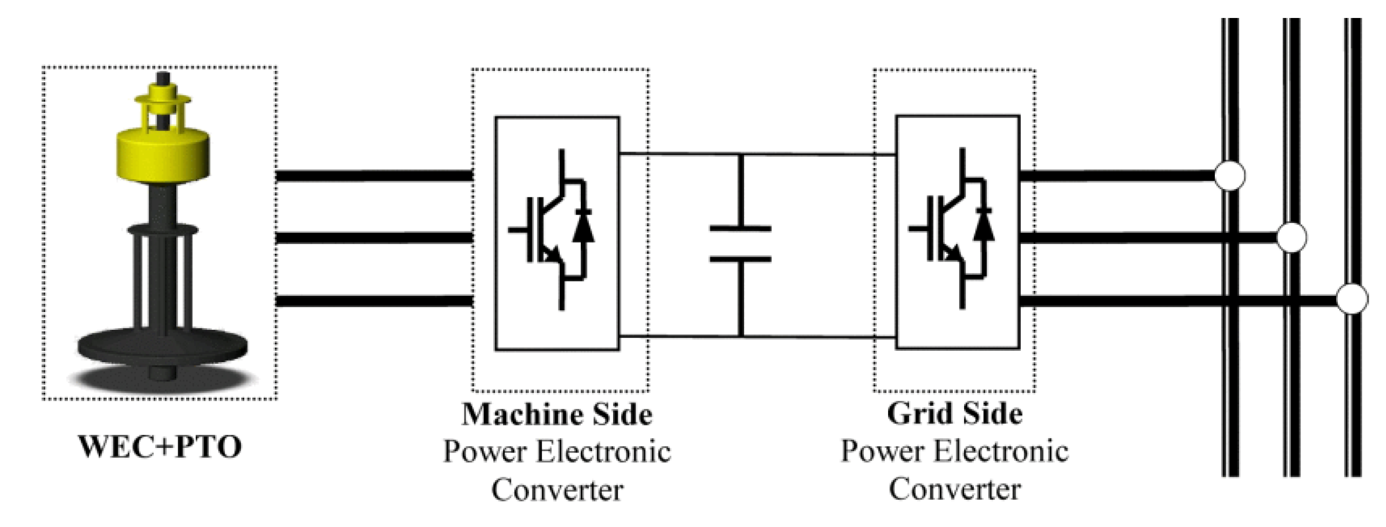
Another source of renewable energy is the energy extracted from waves. Currently there are different systems capable of extracting energy from waves, commonly known as wave nergy converter (WEC). As in the case of other renewable sources, the energy is converted and delivered into the grid by means of a power take-off (PTO). The intermittency associated to the wave energy causes a continuous imbalance between the power generated and the power demanded leading to potential power quality problems, such as voltage and frequency deviations, specially in weak electric grids with high penetration of renewables. The period of the wave energy generated is in the range of 1–10 s, causing frequency variations and voltage distortion, such as flicker and harmonics at the grid connection point [65,66,67,68]. Figure 16 shows a general scheme of WEC solution.
Nunez Forestieri, J. [69] proposes an integrative sizing and EMS based on reinforcement learning (RL) for a HESS (SC/undersea energy storage) applied to grid connected operation of an offsore wave energy source. Different power profiles are used to verify the adaptability of the reinforcement learning-based energy management system (RLEMS). Real-time simulations confirm that the power and energy of the HESS is reduced when EMS is con-sidered in the sizing stage. The number of SC cells and the rate power of the undersea energy storage calculated with the proposed RL-based sizing allows to reduce the required capacity (power and energy) of the HESS to regulate power oscillations. Real-time simulation results are also presented that validate the viability of the proposed method (sizing and EMS) for applications in grid-connected renewable generation systems.
Rajapakse, G. [70] applies a predictive control model to smooth the power delivered to the network of an oscillating water column (OWC) wave energy conversion (WEC). Due to the nature of the resource, as well as the duration of the high-power pulses generated by the air turbine plus permanent magnet synchronous generator (PMSG) on which the study is based, SCs technology is considered the most suitable for this purpose. SCESS is connected to the intermediate DC stage of a back-to-back converter through a bidirectional DC/DC converter. Simulation results are shown in which the model predictive control (MPC) strategy is used, taking as one of the criteria that the SoC of the ESS remains within the limits established to extend the useful life. The THD of the output current obtained in simulations is lower than 5%, below the grid code requirement.

4. Power Grid Connection Applications

In this Section, the applications related to electrical systems, especially in electric grids and microgrids, are collected. Within them, the most published topics have been listed, describing in detail the use of SCs as well as the most relevant bibliography. Those studies are related to the limitations of the renewable energies sources, especially with their oscillatory nature, and the requirement of introducing flexibility in the electrical systems. This entails the integration of an ESS in order to increase the stability of the grid, absorbing or delivering energy, improving the voltage and frequency regulation of the electrical systems.

4.1. Grid Regulation: Voltage and Frequency Compensation

The increasing trend of integrating RES into the electric grids induces in the uncertainty in their operation and control. Their massive penetration into the power systems forces to increase the flexibility of the electric grid, due to the vulnerability of RES towards the unforeseeable variation of meteorological conditions. Related to this issue, ESS are a potential solution to support RES penetration, especially the hybridization of multiple ESS forming a hybrid energy storage system (HESS). This system has ability to fulfil all the requirements of a certain application. However, the limitation of the solution is its complex control strategy, since it plays a key role in optimizing the capabilities of each technology. Related to this scenario, the uses of SCs in the literature are focused on improving the performance of the RES and the electric grids, collecting those studies in the following topics:
  • Smoothing the power generated by renewable energy plants in order to mitigate the harmonics of the power injected to the grid.
  • HESS control strategy improvement, especially controlling the power and energy flow between the renewable generation sources and the storage systems, with the aim of improving their capabilities against the frequency and voltage fluctuations.
  • Introduce the flexibility required by the electric system to improve the voltage and frequency stability.
  • Increasing the lifetime of batteries, using the SCs to suppress the high-frequency oscillations and the batteries to smooth the low-frequency power fluctuations.
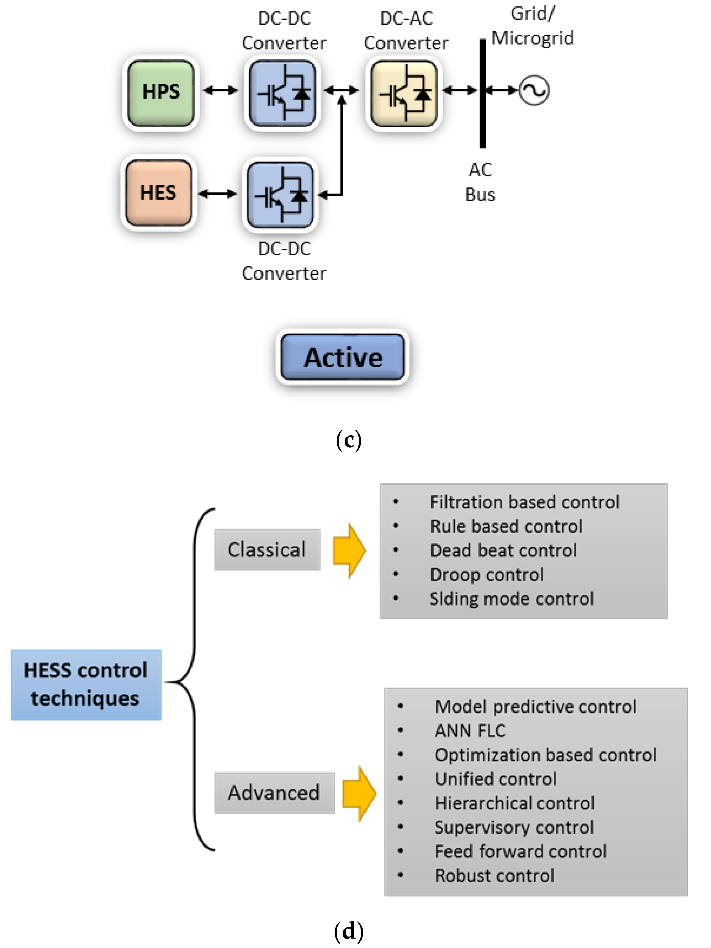
Babu, T.S. [71] presents a review of the control strategies proposed in the literature for HESS. The paper classifies the control techniques into interconnection topologies, classical control strategies, advanced control techniques and real cases studies, being briefly discussed with their limitations, see Figure 17. The study collects the challenges faced when an implementation of HESS for standalone microgrid or a grid connected is made. This paper shows a guide to several control techniques implemented for HESS on grid connection applications.
The study [72] proposes a strategy to manage a HESS in renewable generation systems which currently require controlling bidirectional power flow. The device is composed by a direct connection of a battery and a SCs unit linked through a dc-dc converter. The proposed strategy includes a power control loop which distributes the power flow through each device, achieving an optimized performance, providing grid-frequency regulation and maximizing the lifespan of the batteries, reducing their number of cycles. As in other researches, the SCs perform the fast response, absorbing the high-frequency term and the batteries provide the long-term power fluctuations. The HESS are controlled using a droop control strategy that considers the converter characteristics, SC voltage levels, and power demand.
Manandhar, U. [73] presents a new energy management scheme proposed for a grid connected HESS, composed of the battery and the SC, under different operating scenarios. The objective of the proposed energy management scheme is to reduce the stress in the battery system, controlling the dynamic power sharing between the battery and grid. The study presents a faster DC link voltage regulation to a generation and load disturbances, a reduced rate cycle on the BESS based on its state of charge. Finally, the SCs are in charge of absorbing the high-frequency power fluctuations, reducing the stress on the BESS, and maintaining the SOC limits of energy storage within the safe operating region.
Akram, U. [74] presents an innovative design and operation framework for a BESS and a HESS used for frequency regulation in the electric grid. The proposed design considers the total system cost, the investment, replacement and maintenance cost, as well as the penalty imposed due to not supplying the required regulation service. Moreover, this study shows a comparison based on cost per unit between two scenarios: a HESS and a BESS used both for frequency regulation. The results show that the HESS is more economical.
Nguyen-Huu, T. [75] proposes a coordinated operating control of a HESS (SCs unit and a battery bank) that provides frequency regulation service. The control, based on a droop control with the state-of-charge (SoC) feedback, includes the power flow scheme between the ESSs considering the coverage of the frequency band for each device, as well as the SoC of the SCs and batteries. Moreover, this study provides a guideline for dimensioning the HESS based on based on the smoothing time constant, droop rate, and renewable energy source power rating. The benefits of this method are improving the lifespan of the battery, estimated using a real-time state-of-health (SOH) method based on the temperature, SOH, and throughput degradation.
Pham, V.L. [76] proposes a triple active bridge converter for what will be DC grid in the future. This system is an isolated bidirectional DC-DC converter, used in DC grids and integrated energy systems, composed by different types of renewable energies and storages, such as the photovoltaic and battery systems in grid connection applications or fuel cells and battery/SC in EVs. The advantages of the triple active bridge converter include multiple interfacing ports with isolation, achievable implementation of centralized controls, and improved flexibility of electric systems.
Georgious, R. [77] presents a control strategy for a buck-boost bidirectional converter used in a HESS for DC microgrids. The HESS connected to the DC bus is formed by a Li-ion battery bank and a SCs unit, combined to achieve the energy and power requirements. The control strategy shows a DC bus short-circuit fault-tolerant scheme which provides a protection to HESS and the converter during a short-circuit fault.
Arkhangelski, J. [78] presents a study of a hybrid renewable energy system (HRES), which includes a HESS formed by SCs and batteries, as a reliable source to connect to the grid. This grid connection imposes restrictions relating to the power delivered and its harmonic content. The aim of SCs is to absorb the high-frequency fluctuations of the power along with smoothing the power of the batteries. This study proposes the use of a low-pass second order filter, which splits the high-frequency component for the SCs and the low-frequency component for the battery system. This solution greatly increases the reliability and durability of the HRES. The results show that the proposed strategy improves the lifetime of the batteries (see Figure 18).
Malkawi, A.M.A. [79] shows the benefits of using a SCs-based ESS along with batteries in a HESS to mitigate the impact of high and fast current variations on the losses and lifespan of the batteries. The system is used in DC nanogrids and microgrids with distributed renewable sources, see Figure 19. This paper presents a HESS controlled as a single unit or each ESS module independently, since if the SC interface is controlled independently from the battery interface, the SCs are able to produce both high and short current pulses, reducing the voltage variations, improving the voltage regulation.
Fang, J. [80] proposed a HESS comprising a battery system and SCs to manage the coordinated control of the ESSs as virtual synchronous generators (VSGs). The study uses a control where the SCs attendant the fast-changes power modeled as an inertia and the batteries provide the remaining parts of the VSGs, compensating with slow dynamics and a droop control, the long-term power fluctuations.

4.2. Microgrids

The use of SCs in a microgrid is linked to a HESS, i.e., the use together with batteries. Within this approach, researchers are focused on improving the performance of a microgrid, analyzing the following topics:
  • Lifespan improvement of the batteries, using the batteries to smooth the low-frequency power fluctuations in the long-term, while the SCs suppress the high-frequency oscillations.
  • Capacity and dimensioning optimization of the HESS required to fulfill with the Microgrid restrictions.
  • Consumption reduction by diesel groups or fuel cells.
  • Control strategy improvement of the microgrid, especially in controlling the power and energy flow between the renewable generation sources and storage systems, with the aim of improving their behavior in transients and faults.
  • Voltage and frequency regulation.
Khalid, M. [81] presents a comprehensive review of the research development of the hybrid storage topic over the last two decades. In this paper, each application-focused is thoroughly and independently investigated. The HESS-focused application comprises battery and SC modules, which have complementary characteristics improving their scope in various fields. The review collects research works about regulation of renewable energy sources; grid regulation, especially voltage and frequency compensation; energy storage enhancements, including lifespan improvement, and capacity reduction; and regenerative braking in electric vehicles.
Torkashvand, M. [82] compared a battery ESS and a hybrid energy storage system combining SCs with Li-ion batteries and lead-acid batteries for islanded microgrid applications. This study presents the economical effective of the hybridization, as well as the dimensioning calculation of the ESS to use in the energy management and frequency control of microgrids operating in islanded mode. The results show that the HESS with SC has considerable cost reduction.
Zhu, Y. [83] proposed a strategy based on droop control method for a HESS, comprised of a battery and a SC module, under unbalanced load and nonlinear load conditions. The battery system works in droop mode, providing energy and fundamental active power, i.e., the static performance. Meanwhile, the SC module works in compensation mode, providing the reactive power required, as well as transient changes in the power conditions. This strategy provides better system performance, especially in unbalanced and nonlinear load conditions. Moreover, microgrid stability and the battery lifespan are increased, as well as the power quality.
Oriti, G. [84] presents a novel power flow control system for a remote military microgrid with a HESS, combining batteries and SCs to increase the battery life redirecting the higher frequency current over the SCs. Moreover, this analysis considers several configurations for SCs and filter parameters to achieve the highest cash flow for the overall system, reducing the fuel consumption for the diesel generator. Finally, these results are linked with the sensitivity analysis of the economics of the military microgrid.
Oriti, G. [85] describes an economic analysis combined with a novel power flow control strategy for an energy management system (EMS) involving a HESS. This device is formed by a battery and a SCs module. The aim of the study is increasing the lifetime of the batteries, introducing a SCs module on the EMS to absorb the higher frequency currents, leaving the slow current changes for the batteries. Moreover, the lifetime effect over the economics of the system is analysed.
Akram, U. [86] describes a methodology for the joint capacity optimization of two renewable energy generation system (wind and solar PV) and a HESS, comprised of batteries and SCs. The optimization problem of the sizing the HESS, solar and wind systems of the microgrid comprises the objective of minimising the cost, improving the reliability and reducing the greenhouse gases emissions. The results show that a microgrid with a HESS is more reliable and has lower greenhouse gases emissions and an economical benefit.
Ghosh, S.K. [87] proposes an energy management system (EMS)-based control scheme for DC microgrids with solar photovoltaic systems as the primary generation and energy storage systems, comprised by a battery ESS and SCs. The main feature of the study is to improve the dynamic performance of the microgrid during severe transients, especially in changes of the load demands and power oscillations of the PV units. Moreover, the EMS aims to increase the lifespan of the battery ESS and improve the voltage stability. The control strategy uses proportional-integral (PI) controllers to regulate the switching control actions based on the decision of the EMS achieving the desired objectives.
Kamel, A. [88] presented in the above studies, a control strategy based on a classic PI controller for an EMS and an isolated microgrid is described. It combines PV panels, FC as power sources and batteries and SCs as ESS. The system includes a maximum power point tracking (MPPT) to maximize the harvested energy from PV units. The aim is to optimize the energy management in the microgrid and the cost savings, using different control strategies, and reduce the hydrogen consumption. The PV array supplies the main power and the FC compensates the transient fluctuation of the solar source. Meanwhile, the battery and SC are used to solve the problems of slow response of the FC during the fast change of the load power and to remove the peak power from the system.
Wu, T. [89] introduces an improved hierarchical control strategy which considers the energy storage status of a distributed hybrid energy storage system, leading to the inconsistency of the remaining capacity of the energy storage system in the process of system operation, improving the stability of the microgrid.
Yu, M. [90] proposes a new control method for a HESS to improve the power quality and the fault ride-through capability of islanded forest microgrids. The system is composed by a wind turbine as source and batteries and SCs as energy storage. The method includes a basic control scheme represented by a mode-based sectional coordinated control, and an improved strategy for the HESS, using the batteries to smooth the low-frequency power fluctuations in the long-term, meanwhile the SCs suppress the high-frequency oscillations. A predictive control of the converters is adopted to reduce control delay and ensure the effectiveness of the energy storage power converters. Moreover, as an additional energy storage unit, a wind turbine is used, analysing its capacity of suppressing the huge power disturbance thanks to its large rotating kinetic energy, improving the fault-ride through capacity of the microgrid.

5. Conclusions

The present manuscript describes the most relevant papers that propose the integration of SCs in electric traction drives, renewable energy sources, and grid connection applications.
Regarding the publications related to electric traction drives, the largest number of them are related to the use of SCs in EVs. Regarding heavy-rail catenary supplied vehicles, most publications focus on the analysis of a DC catenary voltage (1.5–3 kV) against AC (25 kV), because DC voltage levels facilitate the integration of SCs without additional power electronics. SCs in heavy-rail vehicles are used to regenerative braking energy recovery and to stabilize the supply voltage. Energy savings with an ESS is around 12–20% and economic viability will depend on the incentives of each country for the energy returned to the grid. In relation to heavy-rail diesel-electric vehicles, there are hardly any publications because there are few vehicles of this type, due to thatsupply energy is based on fossil fuel sources. In light-rail rapid transit vehicles, SCs are proposed as one of the most appropriate technologies to function as a supplementary power source to the main one, absorbing high power peaks and recovering part of the braking energy. In this application there are also papers that highlight, in terms of cost, Li-ion capacitors (higher energy density) technology compared to EDLC technology.
Regarding electric drive for road vehicles, most of the papers suggest the use of SCs to work in a coordinated manner with batteries as an on-board hybrid storage system (HESS). In the case of public transportation catenary-supplied vehicles, the ultimate goal is to replace the catenary with a HESS with charging points in different sections of the road. Different battery technologies are compared, and strategies are proposed in order to split the required power between SCs and batteries. SCs/lithium-ion batteries combination is the one that offers the best results from a technical point of view. It is also contemplated to replace EDLC technology with Li-ion capacitors due to the latter having a higher energy density (reduction in weight and volume of the ESS), which is an important aspect in on-board systems. The papers related to HEVs study the feasibility of alternative powertrain architectures to the parallel configuration (generally considered the one that offers the best overall efficiency) to reduce fuel consumption when SCs are used as the only ESS. On the other hand, the papers related to EVs study the inclusion of SCs as part of the power system to extend the useful life of the batteries. In both cases (HEVs and EVs), an EMS is necessary to maximize the efficiency of the entire system. Controllers based on fuzzy logic and adaptive algorithm are considered essential tools to optimize the power distribution between SCs and batteries in the case of EVs.
Regarding the papers related to the inclusion of SCs in renewable energy systems (wind and PV solar), most of them consider a HESS (SCs/batteries). In the particular case of wave energy systems, SCs are considered as single and sufficient ESS due to the nature of the resource (high power and low energy peaks) and due to that main requirement is reduction of power oscillations. Solar PV and wind power systems need higher energy density ESS (e.g., batteries) in addition to SCs. The papers related to the inclusion of SCs in solar and wind applications are based on studying the optimal configuration for the connection of the HESS. Multi-objective optimization algorithms are also proposed for dimensioning of energy storage system and control strategies (e.g., low pass filter) to split the required power between both ESS. On the other hand, in wave energy applications the use of reinforcement learning-based energy management system is proposed in the SCESS sizing methodology to reduce and optimize the power and energy required. On the other hand, it is necessary to take into account the SoC of the ESS in the control strategy for the operation of the system.
Regarding the power grids applications, SCs are focused on improve their performance. The results of the studies show that the use of SCs together with batteries as a HESS improves the voltage and frequency stability of the electric grids, as well as the flexibility of the system allowing to introduce a higher number of renewable energy plants. Moreover, the SCs allow to use an advanced control strategy for the HESS, improving their efficiency and their capabilities against frequency and voltage fluctuations. Finally, the use of a HESS, composed by a high energy system and a SC based ESS, allows to dimension the system with high accuracy in order to fulfill the grid codes requirements and minimize its cost and maintenance.
In a nutshell, some generic conclusions of the use of SCs in the mentioned applications are:
  • SCs can act as a buffer against large magnitudes and rapid fluctuations in power and for recycling the regenerative braking energy in electric traction vehicles.
  • In order to ensure the suitability of SCs in certain applications, it is necessary to define the operating modes of the system, considering the load conditions and taking into account in the control strategy the SoC of ESS. It is also a very important a good dimensioning methodology of energy storage system taking into account the proposed EMS.
  • In some cases, HESS can be the best option, but it is necessary to define a control strategy (optimization algorithm) to split the required power between both ESS. This optimization has to take into consideration the cost analysis, the aging of ESS, and weight and volume in the case of on-board systems.
  • Remuneration policies for energy returned to the grid and grid code compliance will play a key role in integrating ESS into industrial applications.

Author Contributions

Conceptualization G.N. and J.T.; investigation, G.N., M.B., M.S.-H. and J.T.; writing—original draft preparation, G.N., J.T. and J.N.; writing—review and editing, M.S.-H., M.L. and M.B.; visualization, G.N., J.N. and M.S.-H.; complete review and adding contents, M.L. All authors have read and agreed to the published version of the manuscript.

Funding

This research received no external funding.

Institutional Review Board Statement

Not applicable.

Informed Consent Statement

Not applicable.

Data Availability Statement

Not applicable.

Conflicts of Interest

The authors declare no conflict of interest.

References

  1. Faraji, S.; Ani, F.N. The development supercapacitor from activated carbon by electroless plating—A review. Renew. Sustain. Energy Rev. 2015, 42, 823–834. [Google Scholar] [CrossRef]
  2. EASE. European Energy Storage Technology Development Roadmap—2017; EERA: Brussels, Belgium, 2017. [Google Scholar]
  3. International Electrotechnical Commission. Electrical Energy Storage—White Paper; International Electrotechnical Commission: Geneva, Switzerland, 2011; pp. 1–78. [Google Scholar]
  4. Beaudin, M.; Zareipour, H.; Schellenberg, A.; Rosehart, W. Energy Storage for Mitigating the Variability of Renewable Electricity Sources. Energy Storage Smart Grids Plan. Oper. Renew. Var. Energy Resour. 2014, 14, 1–33. [Google Scholar]
  5. FutureBridge Green Ammonia for Energy Storage—FutureBridge. Available online: https://www.futurebridge.com/industry/perspectives-energy/green-ammonia-for-energy-storage/ (accessed on 2 May 2021).
  6. Zhang, L.; Hu, X.; Wang, Z.; Sun, F.; Dorrell, D.G. A review of supercapacitor modeling, estimation, and applications: A control/management perspective. Renew. Sustain. Energy Rev. 2018, 81, 1868–1878. [Google Scholar] [CrossRef]
  7. Navarro, G.; Nájera, J.; Torres, J.; Blanco, M.; Santos, M.; Lafoz, M. Development and experimental validation of a supercapacitor frequency domain model for industrial energy applications considering dynamic behaviour at high frequencies. Energies 2020, 13, 1156. [Google Scholar] [CrossRef] [Green Version]
  8. Buller, S.; Karden, E.; Kok, D.; De Doncker, R.W. Modeling the dynamic behavior of supercapacitors using impedance spectroscopy. IEEE Trans. Ind. Appl. 2002, 38, 1622–1626. [Google Scholar] [CrossRef]
  9. Rafik, F.; Gualous, H.; Gallay, R.; Crausaz, A.; Berthon, A. Frequency, thermal and voltage supercapacitor characterization and modeling. J. Power Sources 2007, 165, 928–934. [Google Scholar] [CrossRef]
  10. Lajnef, W.; Vinassa, J.M.; Briat, O.; Azzopardi, S.; Woirgard, E. Characterization methods and modelling of ultracapacitors for use as peak power sources. J. Power Sources 2007, 168, 553–560. [Google Scholar] [CrossRef]
  11. Zhang, L.; Wang, Z.; Hu, X.; Sun, F.; Dorrell, D.G. A comparative study of equivalent circuit models of ultracapacitors for electric vehicles. J. Power Sources 2015, 274, 899–906. [Google Scholar] [CrossRef]
  12. Grbovic, P.J. Ultra-Capacitors in Power Conversion Systems: Analysis, Modeling and Design in Theory and Practice; John Wiley and Sons: Chichester, UK, 2014. [Google Scholar]
  13. Berrueta, A.; San Martín, I.; Hernández, A.; Ursúa, A.; Sanchis, P. Electro-thermal modelling of a supercapacitor and experimental validation. J. Power Sources 2014, 259, 154–165. [Google Scholar] [CrossRef]
  14. Ghodbane, O.; Ataherian, F.; Wu, N.L.; Favier, F. In situ crystallographic investigations of charge storage mechanisms in MnO 2-based electrochemical capacitors. J. Power Sources 2012, 206, 454–462. [Google Scholar] [CrossRef]
  15. Torres, J.; Moreno-Torres, P.; Navarro, G.; Blanco, M.; Lafoz, M. Fast energy storage systems comparison in terms of energy efficiency for a specific application. IEEE Access 2018, 6, 40656–40672. [Google Scholar] [CrossRef]
  16. Maxwell Technologies. Application Note 1007239: Test Procedures for Capacitance, ESR, Leakage Current and Self-Discharge Characterizations of Ultracapacitors; Maxwell Technologies: San Diego, CA, USA, 2015. [Google Scholar]
  17. Tevi, T.; Takshi, A. Modeling and simulation study of the self-discharge in supercapacitors in presence of a blocking layer. J. Power Sources 2015, 273, 857–862. [Google Scholar] [CrossRef]
  18. Navarro, G.; Torres, J.; Blanco, M.; González, M.; Lafoz, M. Test Bench Implementation to Calibrate Ageing and Voltage Unbalance in a Large Series Connection of Supercapacitors. In Proceedings of the 2018 20th European Conference on Power Electronics and Applications (EPE’18 ECCE Europe), Riga, Latvia, 17–21 September 2018; IEEE: New York, NY, USA, 2018. [Google Scholar]
  19. Maxwell Technologies. Ultracapacitors, Supercapacitors, Microelectronics and High Voltage. Available online: https://www.maxwell.com/images/documents/K2Series_DS_1015370_5_20141104.pdf (accessed on 21 October 2017).
  20. Skeleton Technologies GmbH. Data Sheet Ultracapacitor SCA0500 to SCA3200 Weldable Cells & SCA0300 PCB-Mountable Cell; Skeleton Technologies GmbH: Großröhrsdorf, Germany, 2020. [Google Scholar]
  21. IOXUS. Data Sheet Ultracapacitor; IOXUS: Oneonta, NY, USA, 2019. [Google Scholar]
  22. EATON. XL60 Supercapacitors Cylindrical Cells; EATON: Dublin, Ireland, 2017. [Google Scholar]
  23. KAMCAP Power KAMCAP Supercapacitors. Available online: https://www.kamcappower.com/products/winding-type-2.7-volt-super-capacitors/ (accessed on 27 January 2021).
  24. LS Mtron Ultracapacitor Products All View POPUP | LS Mtron. Available online: https://www.lsmtron.com/page/popup/productAllView.asp?divisionCode=D0700 (accessed on 27 January 2021).
  25. VINATECH Supercapacitor |PRODUCTS| VINATECH. Available online: https://www.vinatech.com/spn/product/supercapacitor.php (accessed on 16 May 2021).
  26. Berrueta, A.; Ursua, A.; Martin, I.S.; Eftekhari, A.; Sanchis, P. Supercapacitors: Electrical Characteristics, Modeling, Applications, and Future Trends. IEEE Access 2019, 7, 50869–50896. [Google Scholar] [CrossRef]
  27. Rufer, A.; Hotellier, D.; Barrade, P. A supercapacitor-based energy storage substation for voltage compensation in weak transportation networks. IEEE Trans. Power Deliv. 2004, 19, 629–636. [Google Scholar] [CrossRef]
  28. UIC. High Speed Rail—Fast Track to Sustainable Mobility; International Union of Railways: Paris, France, 2012. [Google Scholar]
  29. Dutta, O.; Saleh, M.; Khodaparastan, M.; Mohamed, A. A dual-stage modeling and optimization framework for wayside energy storage in electric rail transit systems. Energies 2020, 13, 1614. [Google Scholar] [CrossRef] [Green Version]
  30. Khodaparastan, M.; Mohamed, A. Flywheel vs. Supercapacitor as wayside energy storage for electric rail transit systems. Inventions 2019, 4, 62. [Google Scholar] [CrossRef] [Green Version]
  31. Chen, J.; Hu, H.; Ge, Y.; Wang, K.; Huang, W.; He, Z. An energy storage system for recycling regenerative braking energy in high-speed railway. IEEE Trans. Power Deliv. 2021, 36, 320–330. [Google Scholar] [CrossRef]
  32. Zhong, Z.; Yang, Z.; Fang, X.; Lin, F.; Tian, Z. Hierarchical Optimization of an On-Board Supercapacitor Energy Storage System Considering Train Electric Braking Characteristics and System Loss. IEEE Trans. Veh. Technol. 2020, 69, 2576–2587. [Google Scholar] [CrossRef]
  33. Xu, C.; Chen, Z.; Cheng, K.W.E.; Wang, X.; Ho, H.F. A supercapacitor-based method to mitigate overvoltage and recycle the energy of pantograph arcing in the high speed railway. Energies 2019, 12, 1214. [Google Scholar] [CrossRef] [Green Version]
  34. Diesel Locomotives |The Railway Technical Website| PRC Rail Consulting Ltd. Available online: http://www.railway-technical.com/trains/rolling-stock-index-l/diesel-locomotives/ (accessed on 19 April 2021).
  35. Da Silva Moraes, C.G.; Brockveld Junior, S.L.; Heldwein, M.L.; Franca, A.S.; Vaccari, A.S.; Waltrich, G. Power Conversion Technologies for a Hybrid Energy Storage System in Diesel-Electric Locomotives. IEEE Trans. Ind. Electron. 2020, 1. [Google Scholar] [CrossRef]
  36. Tram modernisation in Alexandria/Egypt—Urban Transport Magazine. Available online: https://www.urban-transport-magazine.com/en/tram-modernisation-in-alexandria-egypt/ (accessed on 19 April 2021).
  37. Zhang, X.; Zhang, H.; Li, H.; Jiao, Y.; Liao, H.; Peng, J.; Huang, Z. Cooperative Charging of Supercapacitor Trams with Current Overshoot Suppression. IEEE Trans. Ind. Appl. 2020, 56, 4155–4165. [Google Scholar]
  38. Ciccarelli, F.; Del Pizzo, A.; Iannuzzi, D. Improvement of energy efficiency in light railway vehicles based on power management control of wayside lithium-ion capacitor storage. IEEE Trans. Power Electron. 2014, 29, 275–286. [Google Scholar] [CrossRef]
  39. Zhu, F.; Yang, Z.; Xia, H.; Lin, F. Hierarchical Control and Full-Range Dynamic Performance Optimization of the Supercapacitor Energy Storage System in Urban Railway. IEEE Trans. Ind. Electron. 2018, 65, 6646–6656. [Google Scholar] [CrossRef]
  40. Lafoz, M.; Navarro, G.; Torres, J.; Santiago, Á.; Nájera, J.; Santos-Herran, M.; Blanco, M. Power Supply Solution for Ultrahigh Speed Hyperloop Trains. Smart Cities 2020, 3, 642–656. [Google Scholar] [CrossRef]
  41. First Solaris Trolleybuses Delivered to Norway In Advance of December Launch. Available online: https://www.focustransport.org/2020/10/ (accessed on 19 April 2021).
  42. Cignini, F.; Genovese, A.; Ortenzi, F.; Alessandrini, A.; Berzi, L.; Pugi, L.; Barbieri, R. Experimental data comparison of an electric minibus equipped with different energy storage systems. Batteries 2020, 6, 26. [Google Scholar] [CrossRef]
  43. Soltani, M.; Ronsmans, J.; Kakihara, S.; Jaguemont, J.; Van den Bossche, P.; van Mierlo, J.; Omar, N. Hybrid battery/lithium-ion capacitor energy storage system for a pure electric bus for an urban transportation application. Appl. Sci. 2018, 8, 1176. [Google Scholar] [CrossRef] [Green Version]
  44. Tran, D.D.; Vafaeipour, M.; El Baghdadi, M.; Barrero, R.; Van Mierlo, J.; Hegazy, O. Thorough state-of-the-art analysis of electric and hybrid vehicle powertrains: Topologies and integrated energy management strategies. Renew. Sustain. Energy Rev. 2020, 119, 109596. [Google Scholar] [CrossRef]
  45. Passalacqua, M.; Lanzarotto, D.; Repetto, M.; Vaccaro, L.; Bonfiglio, A.; Marchesoni, M. Fuel Economy and EMS for a Series Hybrid Vehicle Based on Supercapacitor Storage. IEEE Trans. Power Electron. 2019, 34, 9966–9977. [Google Scholar] [CrossRef]
  46. Passalacqua, M.; Carpita, M.; Gavin, S.; Marchesoni, M.; Repetto, M.; Vaccaro, L.; Wasterlain, S. Supercapacitor storage sizing analysis for a series hybrid vehicle. Energies 2019, 12, 1759. [Google Scholar] [CrossRef] [Green Version]
  47. Blockchain-Based Electric Vehicle Receives $1M from Canadian Government—European Blockchain Convention. Available online: https://eblockchainconvention.com/blockchain-based-electric-vehicle-receives-1m-from-canadian-government/ (accessed on 19 April 2021).
  48. Hussain, S.; Ali, M.U.; Park, G.-S.; Nengroo, S.H.; Khan, M.A.; Kim, H.-J. A Real-Time Bi-Adaptive Controller-Based Energy Management System for Battery–Supercapacitor Hybrid Electric Vehicles. Energies 2019, 12, 4662. [Google Scholar] [CrossRef] [Green Version]
  49. Sadeq, T.; Wai, C.K.; Morris, E.; Tarboosh, Q.A.; Aydogdu, O. Optimal Control Strategy to Maximize the Performance of Hybrid Energy Storage System for Electric Vehicle Considering Topography Information. IEEE Access 2020, 8, 216994–217007. [Google Scholar] [CrossRef]
  50. Shchur, I.; Biletskyi, Y. Interconnection and damping assignment passivity-based control of semi-active and active battery/supercapacitor hybrid energy storage systems for stand-alone photovoltaic installations. In Proceedings of the 14th International Conference on Advanced Trends in Radioelectronics, Telecommunications and Computer Engineering (TCSET), Slavske, Ukraine, 20–24 February 2018; Institute of Electrical and Electronics Engineers Inc.: Piscataway, NJ, USA, 2018; Volume 2018, pp. 324–329. [Google Scholar]
  51. Yu, H.; Castelli-Dezza, F.; Cheli, F.; Tang, X.; Hu, X.; Lin, X. Dimensioning and Power Management of Hybrid Energy Storage Systems for Electric Vehicles with Multiple Optimization Criteria. IEEE Trans. Power Electron. 2021, 36, 5545–5556. [Google Scholar] [CrossRef]
  52. Shi, R.; Semsar, S.; Lehn, P.W. Single-Stage Hybrid Energy Storage Integration in Electric Vehicles Using Vector Controlled Power Sharing. IEEE Trans. Ind. Electron. 2020. [Google Scholar] [CrossRef]
  53. Lu, W.; Zhao, J.; Dong, Y.; Wang, B.; Shen, J. 100 kW electric bus wireless charging system with calculating method for hybrid energy storage capacity. In Proceedings of the 8th International Conference on Power Electronics Systems and Applications: Future Mobility and Future Power Transfer (PESA), Hong Kong, China, 7–10 December 2020; Institute of Electrical and Electronics Engineers Inc.: Piscataway, NJ, USA, 2020. [Google Scholar]
  54. Geng, Y.; Yang, Z.; Lin, F. Design and Control for Catenary Charged Light Rail Vehicle Based on Wireless Power Transfer and Hybrid Energy Storage System. IEEE Trans. Power Electron. 2020, 35, 7894–7903. [Google Scholar] [CrossRef]
  55. Azad, A.; Pantic, Z. A Supercapacitor-based Converter Topology for Grid-Side Power Management in Dynamic Wireless Charging Systems. In Proceedings of the ITEC 2019—2019 IEEE Transportation Electrification Conference and Expo; Institute of Electrical and Electronics Engineers Inc.: Piscataway, NJ, USA, 2019. [Google Scholar]
  56. Ruddell, S.; Madawala, U.K.; Thrimawithana, D.J. A Wireless EV Charging Topology with Integrated Energy Storage. IEEE Trans. Power Electron. 2020, 35, 8965–8972. [Google Scholar] [CrossRef]
  57. Wu, Y.; Zhang, H.; Liu, M.; Kang, N.; Ma, C. Optimization of super capacitor buffered dynamic wireless power transfer system. In Proceedings of the 2020 IEEE PELS Workshop on Emerging Technologies: Wireless Power Transfer, WoW 2020, Seoul, Korea, 15–19 November 2020; Institute of Electrical and Electronics Engineers Inc.: Piscataway, NJ, USA, 2020; pp. 364–369. [Google Scholar]
  58. Baggini, A. Handbook of Power Quality. Available online: https://www.wiley.com/en-us/Handbook+of+Power+Quality-p-9780470754238 (accessed on 19 April 2021).
  59. Ackermann, T. (Ed.) Wind Power in Power Systems; John Wiley and Sons, Ltd.: Chichester, UK, 2012. [Google Scholar]
  60. Panhwar, I.H.; Ahmed, K.; Seyedmahmoudian, M.; Stojcevski, A.; Horan, B.; Mekhilef, S.; Aslam, A.; Asghar, M. Mitigating Power Fluctuations for Energy Storage in Wind Energy Conversion System Using Supercapacitors. IEEE Access 2020, 8, 189747–189760. [Google Scholar] [CrossRef]
  61. Liu, J.; Zhang, L. Strategy design of hybrid energy storage system for smoothing wind power fluctuations. Energies 2016, 9, 991. [Google Scholar] [CrossRef] [Green Version]
  62. Cabrane, Z.; Kim, J.; Yoo, K.; Ouassaid, M. HESS-based photovoltaic/batteries/supercapacitors: Energy management strategy and DC bus voltage stabilization. Sol. Energy 2021, 216, 551–563. [Google Scholar] [CrossRef]
  63. Palla, N.; Seshadri Sravan Kumar, V. Coordinated Control of PV-Ultracapacitor System for Enhanced Operation under Variable Solar Irradiance and Short-Term Voltage Dips. IEEE Access 2020, 8, 211809–211819. [Google Scholar] [CrossRef]
  64. Ma, W.; Wang, W.; Wu, X.; Hu, R.; Tang, F.; Zhang, W.; Han, X.; Ding, L. Optimal Allocation of Hybrid Energy Storage Systems for Smoothing Photovoltaic Power Fluctuations Considering the Active Power Curtailment of Photovoltaic. IEEE Access 2019, 7, 74787–74799. [Google Scholar] [CrossRef]
  65. Lafoz, M.; Blanco, M.; Ramírez, D. Grid connection for wave power farms. In Proceedings of the 14th European Conference on Power Electronics and Applications, Birmingham, UK, 30 August–1 September 2011; IEEE: Birmingham, UK, 2011; pp. 1–10. [Google Scholar]
  66. Blavette, A.; O’Sullivan, D.L.; Alcorn, R.; Lewis, T.W.; Egan, M.G. Impact of a medium-size wave farm on grids of different strength levels. IEEE Trans. Power Syst. 2014, 29, 917–923. [Google Scholar] [CrossRef]
  67. Eltigani, D.; Masri, S. Challenges of integrating renewable energy sources to smart grids: A review. Renew. Sustain. Energy Rev. 2015, 52, 770–780. [Google Scholar] [CrossRef]
  68. MaRINET2. MaRINET2 Wave Facilities. Available online: http://www.marinet2.eu/facilities/wave/ (accessed on 19 April 2021).
  69. Nunez Forestieri, J.; Farasat, M. Integrative sizing/real-Time energy management of a hybrid supercapacitor/undersea energy storage system for grid integration of wave energy conversion systems. IEEE J. Emerg. Sel. Top. Power Electron. 2020, 8, 3798–3810. [Google Scholar] [CrossRef]
  70. Rajapakse, G.; Jayasinghe, S.; Fleming, A.; Negnevitsky, M. Grid integration and power smoothing of an oscillatingwater column wave energy converter. Energies 2018, 11, 1871. [Google Scholar] [CrossRef] [Green Version]
  71. Babu, T.S.; Vasudevan, K.R.; Ramachandaramurthy, V.K.; Sani, S.B.; Chemud, S.; Lajim, R.M. A Comprehensive Review of Hybrid Energy Storage Systems: Converter Topologies, Control Strategies and Future Prospects. IEEE Access 2020, 8, 148702–148721. [Google Scholar] [CrossRef]
  72. Rocabert, J.; Capo-Misut, R.; Munoz-Aguilar, R.S.; Candela, J.I.; Rodriguez, P. Control of Energy Storage System Integrating Electrochemical Batteries and Supercapacitors for Grid-Connected Applications. IEEE Trans. Ind. Appl. 2019, 55, 1853–1862. [Google Scholar] [CrossRef]
  73. Manandhar, U.; Ukil, A.; Gooi, H.B.; Tummuru, N.R.; Kollimalla, S.K.; Wang, B.; Chaudhari, K. Energy management and control for grid connected hybrid energy storage system under different operating modes. IEEE Trans. Smart Grid 2019, 10, 1626–1636. [Google Scholar] [CrossRef]
  74. Akram, U.; Khalid, M. A Coordinated Frequency Regulation Framework Based on Hybrid Battery-Ultracapacitor Energy Storage Technologies. IEEE Access 2017, 6, 7310–7320. [Google Scholar] [CrossRef]
  75. Nguyen-Huu, T.-A.; Nguyen, V.T.; Hur, K.; Shim, J.W. Coordinated Control of a Hybrid Energy Storage System for Improving the Capability of Frequency Regulation and State-of-Charge Management. Energies 2020, 13, 6304. [Google Scholar] [CrossRef]
  76. Pham, V.L.; Wada, K. Applications of triple active bridge converter for future grid and integrated energy systems. Energies 2020, 13, 1577. [Google Scholar] [CrossRef] [Green Version]
  77. Georgious, R.; Garcia, J.; Sumner, M.; Saeed, S.; Garcia, P. Fault Ride-through power electronic topologies for hybrid energy storage systems. Energies 2020, 13, 257. [Google Scholar] [CrossRef] [Green Version]
  78. Arkhangelski, J.; Roncero-Sánchez, P.; Abdou-Tankari, M.; Vázquez, J.; Lefebvre, G. Control and restrictions of a hybrid renewable energy system connected to the grid: A battery and supercapacitor storage case. Energies 2019, 12, 2776. [Google Scholar] [CrossRef] [Green Version]
  79. Malkawi, A.M.A.; Lopes, L.A.C. Improved dynamic voltage regulation in a droop controlled DC nanogrid employing independently controlled battery and supercapacitor units. Appl. Sci. 2018, 8, 1525. [Google Scholar] [CrossRef] [Green Version]
  80. Fang, J.; Tang, Y.; Li, H.; Li, X. A Battery/Ultracapacitor Hybrid Energy Storage System for Implementing the Power Management of Virtual Synchronous Generators. IEEE Trans. Power Electron. 2018, 33, 2820–2824. [Google Scholar] [CrossRef]
  81. Khalid, M. A review on the selected applications of battery-supercapacitor hybrid energy storage systems for microgrids. Energies 2019, 12, 4559. [Google Scholar] [CrossRef] [Green Version]
  82. Torkashvand, M.; Khodadadi, A.; Sanjareh, M.B.; Nazary, M.H. A Life Cycle-Cost Analysis of Li-ion and Lead-Acid BESSs and Their Actively Hybridized ESSs with Supercapacitors for Islanded Microgrid Applications. IEEE Access 2020, 8, 153215–153225. [Google Scholar] [CrossRef]
  83. Zhu, Y.; Fan, Q.; Xiong, L.; Zhang, G.; Qian, X. Coordination control strategy for battery-ultracapacitor hybrid energy storage system in microgrids with unbalanced and nonlinear loads. IEEE Access 2019, 7, 111577–111591. [Google Scholar] [CrossRef]
  84. Oriti, G.; Anglani, N.; Julian, A.L. Hybrid Energy Storage Control in a Remote Military Microgrid with Improved Supercapacitor Utilization and Sensitivity Analysis. In IEEE Transactions on Industry Applications; Institute of Electrical and Electronics Engineers Inc.: Piscataway, NJ, USA, 2019; Volume 55, pp. 5099–5108. [Google Scholar]
  85. Oriti, G.; Julian, A.L.; Anglani, N.; Hernandez, G.D. Novel Economic Analysis to Design the Energy Storage Control System of a Remote Islanded Microgrid. IEEE Trans. Ind. Appl. 2018, 54, 6332–6342. [Google Scholar] [CrossRef]
  86. Akram, U.; Khalid, M.; Shafiq, S. An innovative hybrid wind-solar and battery-supercapacitor microgrid system—development and optimization. IEEE Access 2017, 5, 25897–25912. [Google Scholar] [CrossRef]
  87. Ghosh, S.K.; Roy, T.K.; Pramanik, M.A.H.; Sarkar, A.K.; Mahmud, M.A. An energy management system-based control strategy for DC microgrids with dual energy storage systems. Energies 2020, 13, 2992. [Google Scholar] [CrossRef]
  88. Kamel, A.; Rezk, H.; Shehata, N.; Thomas, J. Energy Management of a DC Microgrid Composed of Photovoltaic/Fuel Cell/Battery/Supercapacitor Systems. Batteries 2019, 5, 63. [Google Scholar] [CrossRef] [Green Version]
  89. Wu, T.; Yu, W.; Wang, L.; Guo, L.; Tang, Z. Power distribution strategy of microgrid hybrid energy storage system based on improved hierarchical control. Energies 2019, 12, 3498. [Google Scholar] [CrossRef] [Green Version]
  90. Yu, M.; Zhang, J.; Liu, H. Improved control of forest microgrids with hybrid complementary energy storage. Appl. Sci. 2019, 9, 2523. [Google Scholar] [CrossRef] [Green Version]
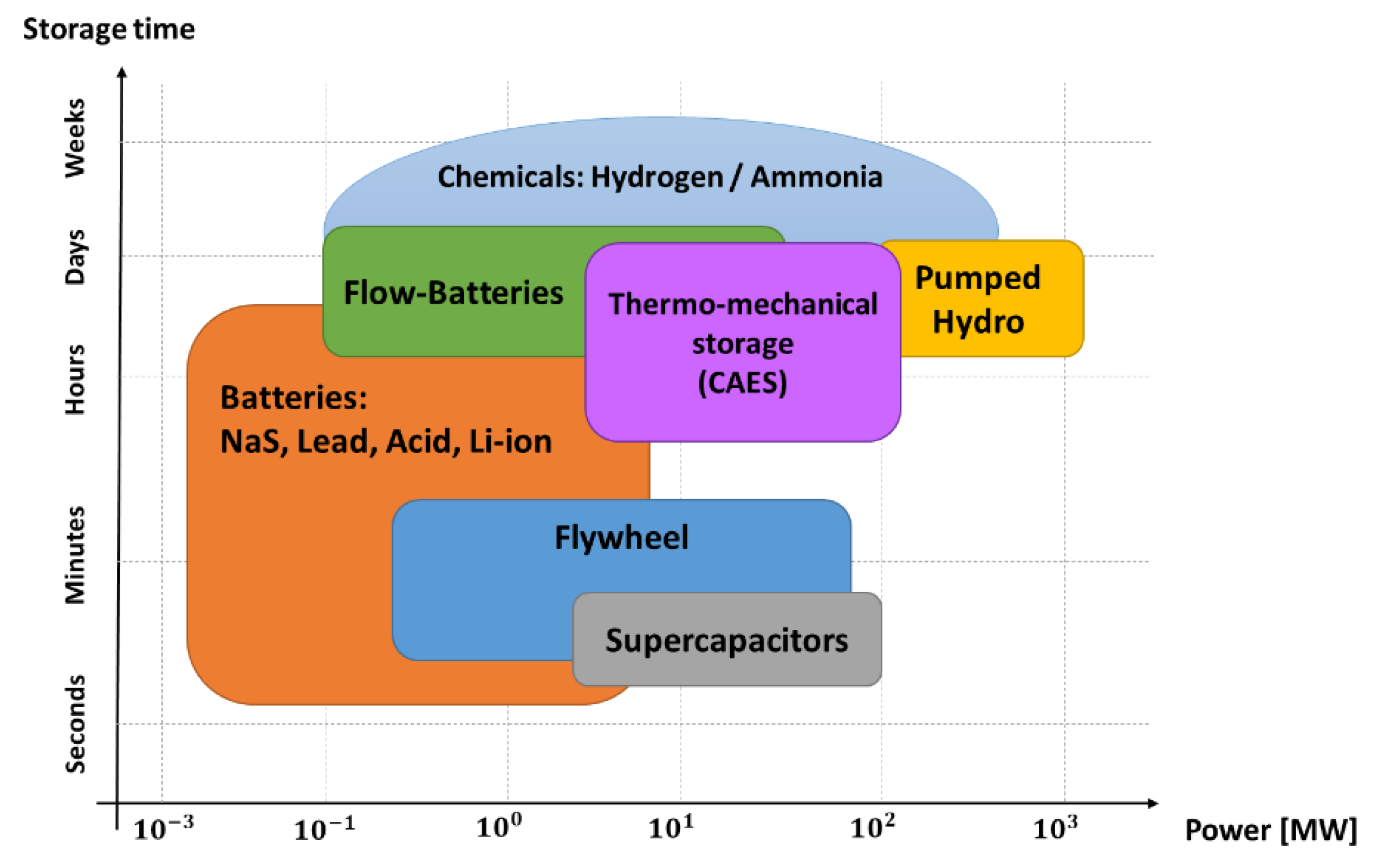
Figure 1. Storage time against the power delivered for electrical energy storage technologies, adapted from [5].
Energies 14 03060 g001
Figure 2. (a) Capacitance variation respect to the voltage; (b) Capacitance variation as a function of the frequency adapted from [7].
Energies 14 03060 g002
Figure 4. Classification of the research publications related to SCs in the last decade respect to their application.
Energies 14 03060 g004
Figure 5. Electrical diagram of a traction converter connected to a high energy/high impedance power source.
Energies 14 03060 g005
Figure 6. Simplified electrical diagram of the traction drive of a heavy-rail catenary supplied vehicles.
Energies 14 03060 g006
Figure 7. Topology of onboard-wayside supercapacitor hybrid energy storage system extracted adapted from [32].
Energies 14 03060 g007
Figure 8. Simplified electrical diagram of the traction drive of diesel-electric vehicles with permanent magnet synchronous generator (PMSG).
Energies 14 03060 g008
Figure 9. Simplified electrical diagram of the traction drive of light-railupplied vehicles.
Energies 14 03060 g009
Figure 10. Simplified electrical diagram of the traction drive of public transportation catenary-supplied vehicles.
Energies 14 03060 g010
Figure 11. Simplified electrical diagrams of different traction drive configurations in HEV adapted from [44]: (a) ICE-based series; (b) ICE-based parallel; (c) ICE-based series-parallel; (d) ICE-based plug-in.
Energies 14 03060 g011aEnergies 14 03060 g011b
Figure 12. Simplified electrical diagram of the traction drive of EVs.
Energies 14 03060 g012
Figure 13. Single stage HESS topology adapted from [52] for its integration in EVs.
Energies 14 03060 g013
Figure 14. (a) Simplified electrical diagram of a variable speed wind turbine with full-scale power converter; (b) Wind Energy Conversion System with proposed HESS adapted from [60].
Energies 14 03060 g014aEnergies 14 03060 g014b
Figure 15. (a) Simplified electrical diagramam of grid connected double conversion PV system; (b) Structure of a multiple converters configuration with maximum power point tracking (MPPT) adapted from [62].
Energies 14 03060 g015aEnergies 14 03060 g015b
Figure 16. Simplified electrical diagramam of a WEC+PTO with linear generator connected to the grid.
Energies 14 03060 g016
Figure 17. Main interconnection topologies for a HESS, formed by a high power storage (HPS) and a high energy storage (HES): (a) passive, (b) semi-active and (c) active adapted from [71]; (d) Classification of HESS control techniques adapted from [71].
Energies 14 03060 g017aEnergies 14 03060 g017b
Figure 18. Scheme of model studied adapted from [78].
Energies 14 03060 g018
Figure 19. Scheme of the SC nanogrid adapted from [79].
Energies 14 03060 g019
Table 1. ESSs Classification according to their nature, data from [2].
NatureElectrical Energy Storage Technology
Electromechanical
  • Flywheels (FESS)
  • Compressed Air (CAES)
  • Hydro Pumped Energy Storage (HPES)
Pumped Energy Storage (HPES)
ElectromagneticSuperconducting Magnetic Energy Storage (SMES)
ElectrochemicalBatteries (BESS)
ChemicalFuel Cells (FCs)
ElectrostaticSupercapacitors (SCs)
Table 2. Classification of the ESSs based on their cycle duration (based on [3,4]).
Cycle Duration (time)Electrical Energy Storage Technology
Very short (<10 s)Capacitors, inductors
Short (1 s to 15 min)SCs, FESS, SMES
Medium (5 min to 24 h)Batteries
Long (days)Batteries, CAES, HPES
Table 3. Comparison based on benefits and drawbacks of the Batteries, flywheels and Supercapacitors.
ESS TechnologyAdvantagesDrawbacks
BatteriesLow self discharge
Narrow range of voltage variation in operation
High energy density
Low installation cost
Accelerated aging with large power pulses
Low recyclability of materials
Reduced operating temperature range
Low power density
Need for a BMS
SupercapacitorsHigh power density
Wide operating temperature range
Ageing not dependent on the duty cycle
More stable efficiency throughout the operating range
Wide voltage variation in operation
Power converter required to operate
Voltage balancing system between cells required
Low energy densisty
Higher cost (€/kWh)
FlywheelsHigh energy density
Power and Energy decoupling
Less ageing than batteries and supercapacitors
Very wide operating temperature range
High self-discharge
High installation cost
Lower efficiency than batteries and SCs
Power converter required
Table 4. Main parameters of SCs cell for different manufacturers.
CharacteristicsMaxwell [19]Skeleton [20]Ioxus [21]EATON [22]Kamcap [23]Ls Mtron [24]Vina Tech [25]Yunakaso [23]
Rated voltage 2.7   V 2.85   V 2.85   V 2.85   V 2.7   V 2.7   V 2.7   V 2.7   V
Initial rated capacitance 3000   F 3200   F 3000   F 3400   F 3000   F 3000   F 3000   F 3000   F
Initial ESR 0.29   m 0.14   m 0.20   m 0.23   m 0.29   m 0.23   m 0.28   m 0.28   m
Operating temperature range [ 40   ° C   ,   65   ° C ]
Maximum current 1900   A 3100   A 2700   A 2700   A 2200   A
Maximum Leakage current 5.2   mA 11   mA 4.5   mA 8   mA 5   mA
Publisher’s Note: MDPI stays neutral with regard to jurisdictional claims in published maps and institutional affiliations.