1. Introduction
The production of sustainable energy is one of the most relevant issues of current times. The increase in polluting emissions and global warming have emphasized the impropriety of fossil fuels, favoring the development of methods to produce clean energy from renewable sources. However, as most of them have a discontinuous nature, storage and management systems are required to secure the generated energy. In this context, the design of efficient and sustainable energy storage devices and systems is therefore a key point to adequately support the energy transition from fossil to renewable sources.
In the field of energy storage, supercapacitors (SCs), and in particular the electrochemical double layer capacitors (EDLCs), have become of great interest thanks to their complementary performance compared to batteries, such as lithium-ion batteries (LIBs). Indeed, EDLCs generally have moderate energy density (generally < 10 Whkg−1) but provide high power (up to 10 kWkg−1) thanks to a fast charge/discharge mechanism, and they also have a significantly high number of life cycles (>>100,000 cycles).
The properties of an EDLC are defined by its electrostatic energy storage mechanism and by its components. These devices consist of two electrodes with a high surface area electrically isolated by a porous dielectric separator. The electrodes include a metal collector (usually aluminum), on which a layer of high porosity active material (usually activated carbon and carbon black) is cast. The electrodes and the dielectric separator are soaked with a conductive medium, typically an electrolyte consisting of a solvent and a conducting salt [
1].
In EDLC devices, the electrolyte is a key component, as the charges are accumulated at the electrode/electrolyte interface (EEI) and the specific energy (E
sp) and the specific power (P
sp) can be expressed as [
2]:
In the equations, C
sp is the specific capacitance, V is the applied potential, m
cell is the mass of electrode active materials, and R
cell is the internal resistance of the device [
3].
The capacitance is mostly determined by the properties of the electrode (available surface, pore distribution, accessibility of the pores) and by the EEI, while the applicable potential and the internal resistance of the device strongly depend on the nature and characteristics of the electrolyte. Hence, aprotic polar organic solvents are often favored over water, as this is subject to redox activity for potentials between 1.0 V and 1.2 V.
A class of water-containing electrolytes capable of overcoming this limit is that of water-in-salt electrolytes (WiS) [
4]. In this type of electrolyte, the water molecules strongly interact with the ions present at very high concentrations, thus increasing the electrochemical stability compared to the classic salt in-water (SiW) solutions [
5]. However, WiS with lithium bis(trifluoromethane)sulfonimide (LiTFSI) presents problems related to the internal resistance of the device due to modest conductivity (21 m LiTFSI 8.2 mScm
−1) and high viscosity (21 m LiTFSI 30.2 mm
2s
−1) [
6]. Furthermore, a rational design of the active material porosity is essential to achieve high performance [
7]. In addition, the development of new technologies should be oriented towards lithium-free devices, given the progressive saturation of its production sites [
8], and with cheap and user-friendly electrolytes [
9]. To extend the applicable potential window using water as an electrolytic component, Hughson et al. recently reported in a communication the use of water–oil microemulsions in the presence of surfactants at a potential of 2.7 V [
10]. However, the high internal resistance recorded (26 Ohm) compromises its concrete application.
Cell voltages of 2.7–3.0 V can be regularly achieved with non-aqueous electrolyte. Moreover, organic solvents can be used in wider temperature ranges than aqueous electrolytes. On the other hand, the electrical conductivity of non-aqueous electrolytes is often significantly lower than that of water, and this contributes to increasing their internal resistance. For these reasons, commercial EDLCs supercapacitors contain acetonitrile (ACN) or propylene carbonate (PC) based electrolytes, but these solvents have limitations for high-voltage applications and risks related to their handling, and are both obtained from fossil feedstock. The need to address these issues represents the driving-force that pushes the scientific community towards the search for new electrolytes.
For a long time, huge efforts have been made to increase the EDLCs performances [
11,
12,
13], and only more recently to also improve safety and ecotoxicological profiles of the used electrolytes. Previous results and new perspectives towards new electrolytes have been described in recent reviews [
14,
15,
16,
17].
Among the non-aqueous electrolytes, a category of wide interest consists in aprotic ionic liquids (AILs) [
18], and more recently also protic liquids (PILs) [
19]. These electrolytes are highly attractive for electrochemical applications due to their stability and safety as non-flammable substances [
20,
21]. However, their efficiency as electrolytes is strongly affected by the electrodes porosity, resulting in a low energy efficiency in combination with electrodes with a high content of micropores [
22]. Furthermore, the high cost of these electrolytes hampered their commercial applications in solvent-free conditions.
A similar approach to that of WiS electrolytes was reported by Stettner et al. [
23], using electrolytes based on protic ionic liquids (PILs) with additions of water (1–3.8%). Despite a considerable improvement of transport properties, the operating voltage of EDLC containing these electrolytes is lower than that of AIL-based EDLCs (from 1.8 V to 2.2 V).
Recent advances regarding electrolytes based on organic solvents concern the study of nitriles, in linear aliphatic chains (glutaronitrile GTN, adiponitrile ADN), branched chains (2-methylglutaronitrile 2MGN) and as functional groups present in methyl esters (3-cyano-propionic acid methyl ester CPAME) [
24]. These solvents reach very high operational potentials (3.5 V), making high-voltage applications possibly able to address the need to increase the EDLC’s specific energy. However, these substances have high acute toxicity (some even fatal in case of inhalation) and health hazards, and therefore they do not seem suitable for common commercial applications.
To increase the performance of the classic ACN-based electrolytic solutions, binary mixtures with other organic solvents have recently been studied. When mixed with dibutyl carbonate (10%−33% v)
, a net increase in performance at low temperatures (up to −60 °C) was reported [
25], while in combination with ethylisopropylsulfone (75–50%) operational potentials of 3.0 V were reached [
26].
Recently investigated nitrile-free organic solvents are 1,2-butylene carbonate (BC) [
27], tetramethoxyglyoxal (TMG) and tetraethoxyglyoxal (TEG) [
28]. A combination of BC with Pyr
14BF
4 provided a potential window of 3.1 V, while modest results were achieved with TMG and TEG due to their relatively high viscosity.
From the point of view of the sustainability of EDLCs, many efforts have been made to obtain active carbonaceous materials and binders from biomass [
29], but this approach is still lacking for the development of non-aqueous electrolytes. In fact, recent papers do not highlight the origin of the investigated electrolytes despite the design of innovative aprotic polar solvents from renewable sources is a topic of great and current interest [
30].
Our research group has long been involved in the study of the catalytic conversion of biomass [
31,
32,
33,
34] and in the valorizations of bio-based molecules derived from renewable feedstock [
35,
36,
37] to produce innovative materials that beneficially replace the traditional ones.
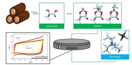
This approach has recently been oriented towards the design of innovative solvents, and, in this manuscript, we report the synthesis of different lactic acid ketals and the investigation on their properties as solvents for electrolytes in symmetrical EDLCs. Lactic acid is a bio-based chemical platform industrially prepared through bacterial fermentation of carbohydrates [
38] and is widely used to produce biodegradable polymers or as starting feedstock for green routes to bulk chemicals productions [
39].
The synthesized solvents have the common structure of 2,2-R,R’-5-methyl-1,3-dioxolan-4-one (DOLOs), which is a chemical platform that allows to selectively evaluate the effect of small structural variations on the electrolyte properties (
Figure 1).
These compounds are already used as precursors of sustainable polymers [
40,
41], but to the best of our knowledge lactic acid derived DOLOs have never been used as solvents in the field of energy storage. The solvent 5-methyl-1,3-dioxolan-4-one displayed performances competitive (C
sp 14.2 Fg
−1, E
sp 13.4 Whkg
−1 and P
sp 22.5 kWkg
−1) with commercial solvents, such as propylene carbonate, and therefore it represents an example of what can be defined as a “Non-Aqueous Sustainable Electrolyte” (NASE).
2. Materials and Methods
2.1. Materials
All synthesized compounds have been characterized through Nuclear Magnetic Resonance (NMR) with a Bruker Avance Ultrashield 400, operating at proton frequency of 400 MHz (
Figures S1–S4). The following abbreviations were used for describing NMR multiplicities: s, singlet; d, doublet; t, triplet; q, quartet; hept, heptet; m, multiplet; dd, doublet of doublets; dt, doublet of triplets; td, triplet of doublets; tt, triplet of triplets.
All electrolytes were prepared and handled in a dry atmosphere using Schlenk line and the appropriate Schlenk line glassware. Lithium tetrafluoroborate (LiBF4) was purchased from Merck KGaA (Darmstadt, Germany). All coin cells were assembled in a dry room. The residual water content in the electrolytes was evaluated through Karl–Fischer titration with a Metrohm 831KF Coulometer.
All electrochemical measurements were recorded using a Gamry Instruments Reference 3000™ potentiostat/galvanostat/FRA, controlled via Gamry Instrument Framework™ software. Data analyses were performed using Gamry Echem Analyst™ software.
The EDLCs electrodes used in this investigation are AC-based, coated on Al-foil, and have been provided as a courtesy by Captop s.r.l. The average mass loading of the electrode was 6 mgcm−2, and the thickness of the active material was 55 µm.
2.2. DOLOs and TEMABF4 Synthesis
DL-lactic acid (purity 90%), paraformaldehyde (reagent grade), paraldehyde (purity 98%), acetone (reagent grade), petroleum ether bp 40–60 °C, p-toluensulfonic acid monohydrated (pTsOH, purity 98%), Amberlite® IR-120 (H+ form) and other solvents and chemicals used for the synthesis of DOLOs were purchased from Merck KGaA (Darmstadt, Germany).
Triethylmethylammonium chloride (purity ≤ 99%), ammonium tetrafluoroborate (purity ≤ 97%) and dry acetonitrile to prepare triethylmethylammonium tetrafluoroborate (TEMABF4) were purchased from Merck KGaA (Darmstadt, Germany).
2.2.1. Synthesis of 2,2,5-trimethyl-1,3-dioxolan-4-one (LA-Me,Me)
For the synthesis of LA-Me,Me, we followed the procedure reported by Miyagawa et al. [
42] with the following modifications.
We used 45.0 g of DL-lactic acid (0.500 mol), 300 mL of a solution 1:1 v/v acetone (2.00 mol) and petroleum ether (bp: 60–80 °C), and 1.42 g of pTsOH (7.50 mmol) as a Brønsted acid catalyst were added in a 500 mL round-bottom flask equipped with a 25 mL Dean–Stark trap and Allihn condenser.
The reaction mixture was refluxed for 24 h under magnetic stirring. After reaction time, the crude mixture was placed in an ice bath and treated with 3.0 g of Na2CO3 (35 mmol) for 30 min. The reaction crude was filtered, and volatile solvent evaporated under reduced pressure. The product was isolated by vacuum distillation (15 mbar) at 50–52 °C. 1H NMR (400 MHz, CDCl3) δ 4.46 (q, J = 6.8 Hz, 1H), 1.59 (s, 3H), 1.52 (s, 3H), 1.46 (d, J = 6.8 Hz, 3H).
2.2.2. Synthesis of 2,5-dimetil-1,3-dioxolan-4-one (LA-Me,H)
For the synthesis of LA-Me,H, we followed the procedure reported by Okada et al. [
43] with the following modifications.
Here, 45.0 g of DL-lactic acid (0.500 mol), 32.0 mL of paraldehyde (0.250 mol), 650 mL of petroleum ether (bp: 60–80 °C) and 3.65 g of Amberlite® IR-120 (H+ form) as heterogeneous Brønsted acid catalyst were added in a 1000 mL round-bottom flask equipped with a 25 mL Dean–Stark trap and Allihn condenser. The reaction was refluxed under magnetic stirring for 5 h. Crude mixture was cooled at room temperature and filtered to remove the catalyst. The volatile solvent was removed, and the product was isolated by vacuum distillation (15 mbar) at 47–49 °C. The product resulted as a mixture of cis-trans stereoisomers in a 70:30 ratio. Major stereoisomer: 1H NMR (400 MHz, CDCl3) δ 5.64 (q, 1H, J = 5.0 Hz), 4.35 (q, 1H, J = 7.0 Hz).1.59 (d, 3H, J = 5.0 Hz), 1.52 (d, 3H, J = 7.0 Hz). Minor stereoisomer: 1H NMR (400 MHz, CDCl3) δ 5.84 (q, 1H, J = 5.0 Hz), 4.50 (q, 1H, J = 7.0 Hz), 1.55 (d, 3H, J = 5.0 Hz), 1.48 (d, 3H, J = 7.0 Hz).
2.2.3. Synthesis of 5-methyl-1,3-dioxolan-4-one (LA-H,H)
For the synthesis of LA-H,H we followed the procedure reported by Cairns et al. [
40] with the following modifications.
Here, 45.0 g of DL-lactic acid (0.500 mol), 22.5 g of paraformaldehyde (0.750 mol), 300 mL of petroleum ether (bp: 60–80 °C) and 1.5 g of pTsOH (0.0080 mol) as a Brønsted acid catalyst were added in a 500 mL round-bottom flask equipped with a 25 mL Dean-Stark trap and Allihn condenser. The reaction was refluxed under vigorous magnetic stirring for 24 h. After reaction time, the crude mixture was cooled in an ice bath and treated with 3.0 g of Na2CO3 (0.035 mol) for 30 min. The reaction crude was then filtered, and volatile solvent evaporated under reduced pressure. The product was isolated by vacuum distillation (15 mbar) at 45–47 °C. 1H NMR (400 MHz, CDCl3) δ 5.51 (s, 1H), 5.38 (s, 1H), 4.27 (q, J = 6.8, 1H), 1.47 (d, J = 6.8, 3H).
2.2.4. Preparation of Triethylmethylammonium Tetrafluoroborate (TEMABF4)
For the synthesis of TEMABF4, a conventional procedure was followed, exploiting the different solubilities of the desired product and the ammonium chloride.
Here, 22.7 g (0.150 mol) of triethylmethylammonium chloride (TEMACl) were added in a 250 mL round-bottom flask and dissolved in 150 mL of dry acetonitrile. After complete solubilization, 18.9 g (0.180 mol) of NH4BF4 was added. The resulting suspension was stirred overnight at room temperature. The suspension was filtered to remove the solid, and the mother liquor was concentrated at a reduced pressure and then crystallized with diethyl ether. Purified product was filtered and dried under vacuum at 50 °C overnight, obtaining an almost quantitative yield. 1H NMR (400 MHz, CD3CN) δ 3.23 (q, J = 7.3 Hz, 6H), 2.84 (s, 3H), 1.47 (d, J = 6.8, 3H), 1.24 (tt, J = 7.3 Hz, J14N = 2.0 Hz, 9H). 13C NMR (101 MHz, CDCl3) δ 56.91 (t, J14N = 3 Hz), 47.48 (t, J14N = 4 Hz) 8.19. 19F NMR (376 MHz, CD3CN) δ −151.29 (11B), −151.34 (10B).
2.3. Electrolyte Characterization
Before preparing the electrolytes, the solvents were stored on molecular sieves (3A) until the water content was reduced to 30–40 ppm, as measured by Karl–Fischer titration. The electrolyte conductivity was measured at 20 °C using platinized Pt electrodes (Crison 254). The conductivity meter was previously calibrated with a 0.1 M KCl standard solution (conductivity 12.89 mScm−1 at 25 °C, Hanna Instrument).
The electrochemical stability window (ESW) was evaluated using a Bob’s Cell™ electrochemical cell equipped with three electrodes: Au disc electrode (ø 3 mm, embedded in PEEK) as working electrode, Pt wire as counter electrode and an Ag/Ag
+ quasi-reference electrode in a solution of PC (TEMABF
4 0.1 M and AgNO
3 3 mM). The reference electrode was equipped with a bridge tube filled with supporting electrolyte (PC TEMABF
4 1M) and connected to the cell with glass frits (Vycor
®). Before each measurement, 5 mL of electrolyte was introduced into the cell and purged with nitrogen under magnetic stirring for 10 min. The magnetic stirring was stopped, and the bubbler was moved from purging to vent position to avoid moisture contamination. Linear Sweep Voltammetry (LSV) measurements were then performed from open circuit potential (OCP) towards both positive and negative potentials with a scan rate of 10 mVs
−1.(
Figure S5), to evaluate respectively the anodic (E
ox) and cathodic limits (E
red). The potential limits were explored separately, and each measurement was made with fresh electrodes and electrolytes. These limits represent the maximum applicable potential in a classic 3-electrode set-up experiment, for which a faradic current density is not negligible due to the electrochemical decomposition of the electrolyte.
2.4. Symmetrical EDLC Assembly
Each coin cell (CR2016) was prepared cutting two circular AC-based electrodes (ø 12 mm). A cellulosic separator (ø 18 mm Celgard® battery separator) was used as the dielectric separator. Before being cut, the activated carbon electrodes were placed in a vacuum oven at 80 °C for 10 h, cooled, and stored in a nitrogen atmosphere.
Before being used, all of the coin cell’s components (case, gasket, cap, plate, and spring) were washed and sonicated with detergents, rinsed with ultra-pure water, and dried in a vacuum oven at 80 °C. The cells were assembled in a dry room by placing into the case the first electrode, the dielectric separator, the appropriate electrolytic solution, the second electrode, the plate, the spring and finally the cap. The cells thus prepared were sealed with MSK110 manual hydraulic crimping machine (MTI KJ group™) and tested as symmetrical EDLCs.
2.5. EDLC Characterizations
EDLCs were characterized by cyclic voltammetry (CV), galvanostatic charge-discharge cycles (GCs) and potentiostatic electrochemical impedance spectroscopy (EIS).
The operative voltage (OV) of the investigated electrolytes was defined as the maximum applicable voltage with a Coulombic Efficiency (CE) threshold of 94–95%. CV were recorded with a scan rate of 5 mVs
−1, starting from 0 V and gradually increasing to the final voltage (
Figure S6). The CE was calculated from the ratio between integration of negative (Q
−) and positive (Q
+) voltammogram areas [
44] that represent, respectively, discharge and charge capacitance:
The Capacitance Retention (CR) was defined with CV by the ratio of the specific capacitance (SC
cv) at different scan rates to that recorded with the scan rate of 5 mVs
−1 (4). The CV scan rate was increased from 5 to 200 mVs
−1 in a potential window from 0 V to OV. In the following characterization,
i1/2 Vmax is the current density (Acm
−2) referred to half of the OV,
s is the applied scan rate (Vs
−1) and
d is the active materials loading (gcm
−2) [
45]:
The GC profiles recorded were elaborated to calculate the specific Capacitance (C
sp, Fg
−1) and maximum specific Energy (E
sp, Whkg
−1) and Power (P
sp, kWkg
−1) according to the following equations [
46]:
where
dt/dV is the slope of the discharging profile,
i the applied current, m
tot the total mass (in g for C
sp and kg for E
sp and P
sp) of the active materials for the two electrodes, C the capacitance (F), OV the operative voltage (V), 3600 is expressed in second. The ESR
GC was calculated according to the following Equation (9), where ΔV
ohmic is the ohmic voltage drop at the beginning of discharge and
i was the applied current:
EIS profiles were recorded in the frequency range between 500 kHz and 10 mHz with 5 mVAC perturbation and 10 points per decade. According to analysis reported by Mei et al. [
47], from EIS profile we determined the ESR, the Equivalent Diffusive Resistance (EDR), relative to the ions penetration into the electrode pores, and the bulk resistance (R
bulk), relative to the bulk resistance of the electrolyte in the cell. The different parameters were defined by the segments obtained from the intersection of the Nyquist plot with the x-axis, also exploiting linear fittings in the diffusive-regime (slope ≈ 1) and capacitive-refine (quasi-vertical line). A clarification of the Nyquist plot analysis is shown in
Figure S7. The time constant of the investigated materials was evaluated calculating the imaginary part C
″(ω) of the complex capacitance according to the work of Taberna et al. [
48] and the following equation:
where ω is the applied frequency, Z
′(ω) is the real part of complex impedance related to the Nyquist plot and |Z (ω)|is the impedance modulus related to the Bode plot.
3. Results
3.1. Solvent and Electrolyte Characterization
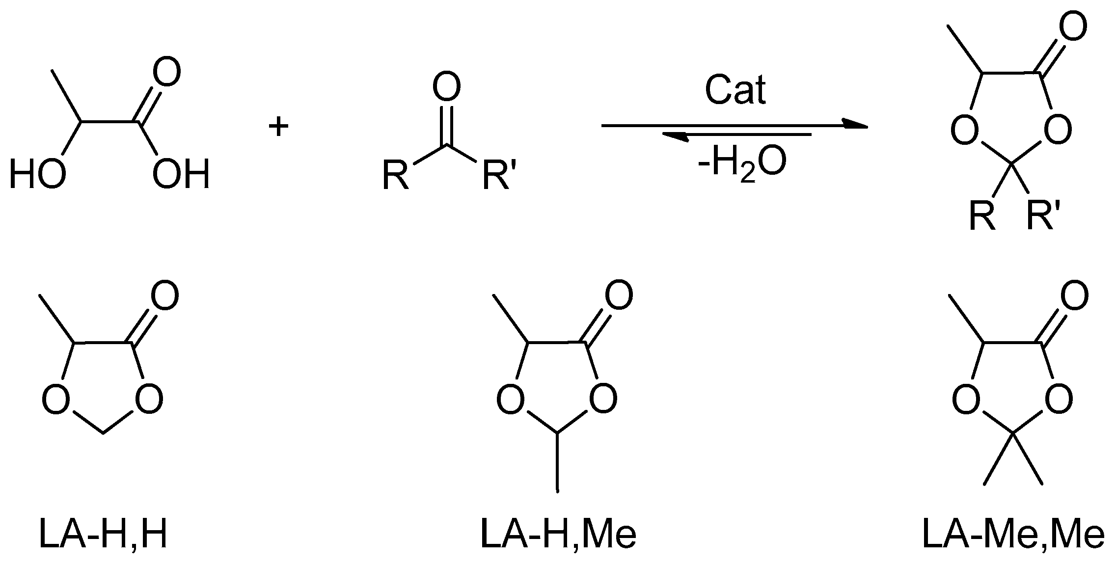
Three dioxolanes with different substituents in position 2 were synthesized performing ketalization reactions between lactic acid (LA) and two different aldehydes (formaldehyde R,R’ = H, acetaldehyde R,R’ = H,Me) or acetone (R,R’ = Me). This panel of substances was chosen to correlate any performance differences to small structural variations. To indicate the different solvents and simplify the discussion, the abbreviation LA-R,R’ will be adopted, where LA indicates the lactic acid fragment and R,R’ explicit the substituents in position 2 (
Figure 2).
The ketals synthesis is an equilibrium reaction, and therefore it was necessary to use a Dean-Stark trap to remove water from the reaction mixture and favor the products formation. A synthesis that implies formation of water as a by-product, such as the ketalization reaction, is preferable to other synthetic pathways as water does not contribute to the E-factor of the reaction. Nevertheless, in order to increase the sustainability of the whole process, water-removal technologies that do not involve the use of solvents, such as pervaporation, will be explored in the future [
49].
The investigated compounds are potentially obtainable from renewable sources, as there are green industrial routes to lactic acid and the other reactants starting from bio-based feedstocks [
50,
51].
However, to consider these compounds as sustainable solvents, it is essential to evaluate their intrinsic safety (flammability, toxicological profile), and the environmental impact in case of accidental release (ecological profile). To assess their flammability, the flashpoint was estimated using the method reported by R.W. Prugh [
52].
Table 1 reports the calculated flash point of the produced DOLOs, their boiling temperature at atmospheric pressure, and the stoichiometric concentration in air (CST) expressed as a volume percentage used to estimate the flash points.
DOLOs have an intermediate flash point between those of the two traditional EDLCs solvents (fp
ACN = 2 °C; fp
PC = 132 °C) and are hence suitable for applications in energy storage devices. The complete evaluation of their ecotoxicological profile is beyond the aim of this study, but it is possible to make some considerations based on their chemical nature. Ketals are a class of substances stable in an alkaline environment but labile in an aqueous and acidic media. Therefore, it is possible to assume that in an atmospheric and physiological environment, these functional groups rapidly hydrolyze, returning the parent reagents [
53]. Lactic acid, acetone, acetaldehyde, and formaldehyde are regularly included in the cellular metabolic pathways at physiological concentrations, and have a low persistence in the natural environment. As an example, the human body produces about 50 g of formaldehyde per day [
54]; the half-life of blood plasma formaldehyde is 1.5 min [
55] and that of atmospheric formaldehyde in daylight is 50 min [
56]. Therefore, the investigated solvents are sustainable alternatives also from the point of view of their ecotoxicological profile.
A preliminary evaluation of their electric performance was carried out by measuring the ionic conductivity and the electrochemical stability window of 1M TEMABF
4 solutions. The results are reported in
Table 2.
Large variations of ionic conductivity were recorded according to the nature of the substituents in position 2. Indeed, LA-H,H showed a conductivity of 8.5 mScm−1, while in presence of additional methyl groups, the conductivity gradually dropped to 1.5 mScm−1 (LA-H,Me) and 200 μScm−1 (LA-Me,Me). Furthermore, LA-Me,Me and LA-H,Me demonstrated a lower solvent capacity because saturated solutions were obtained at concentrations below 1 M, which are therefore unsuitable for applications in SC. A possible application of LA-H,H in Li-ion based devices was also assessed, as 1M solutions of LiBF4 displayed a conductivity of 2.1 mScm−1.
In addition to an adequate conductivity, EDLC applications require that the electrolyte has a wide electrochemical stability window (ESW), that can be preliminary estimated by Linear Sweep Voltammetry (LSW). A large ESW (
Figure S5 and Table S1) was obtained for the electrolyte based on LA-H,H (ΔV 4.50 V, cut-off current densities 1 mAcm
−2), comparable to that recorded for the PC-based electrolyte (ΔV 4.55 V, cut-off current densities 1 mAcm
−2).
Therefore, LA-H,H was selected to evaluate the performance in a symmetrical EDLC with activated carbon based electrodes using TEMABF4 as conventional conducting salt.
3.2. EDLCs Characterization
Cyclic voltammetries (CVs) at different scan rates were performed to evaluate, respectively, the impact of the investigated electrolytes on the maximum operating voltage (OV) and capacitance retention (CR) of EDLCs. For a homogenous comparative analysis,
Figure 3 shows the data with the LA-H,H-based electrolyte, and those of an EDLC prepared with TEMABF
4 1 M in PC.
Initially CVs were recorded at 5 mVs
−1 from 0 to 1 V, and the final potential was gradually increased by 0.2 V in different cycles and described by a rectangular-like shape typical of SCs devices, which deviates from a perfect rectangle (typical of an ideal capacitor) due to the resistance parameters [
46] (
Figure S6). The screening was stopped at 2.6 V when a Coulombic Efficiency (CE) close to 95% was achieved, which was chosen as the minimum efficiency threshold.
Figure 3d shows the CEs as a function of the applied potentials, and the trend is the same for the electrolytes. The decrease of the EC with the increase of the operating potential is due to a gradual contribution of parasitic and irreversible faradic reactions that interfere in the charging capacitance and are absent in discharge capacitance. At 2.6 V the LA-H,H-based EDLCs provided a CE of almost 94.4%, which was slightly lower than that recorded with the PC-electrolyte (95.4%).
After establishing the OV of 2.6 V for both electrolytes, CVs were performed from 0 to 2.6 V, ranging the scan rate from 5 to 200 mVs
−1 (
Figure 3a,b) to evaluate their capacitance retention (CR). The increase of the scan rate strongly influences the response of the EDLCs during CVs; in fact, a marked distortion of the rectangular shape was recorded due to the increase of the ESR, while the decrease of the specific capacity is caused by a lower availability of the electrodes surface. Indeed, at high scan rates the formation of the electric double layer is limited by a lower accessibility of the electrolyte ions in the porous structure of the electrode [
57]. As reported in
Figure 3c, LA-H,H/TEMABF
4 resulted in a greater performance than PC/TEMABF
4. At 200 mVs
−1 a CR of 71% was achieved for LA-H,H/TEMABF
4, while a CR of 62% were obtained with PC/TEMABF
4. Based on these results, the increased performance of LA-H,H/TEMABF
4 cannot be justified by its conductivity, as it was slightly lower than the PC-electrolyte. To understand this behavior, the solvent–salt and electrolyte-electrode interactions should be investigated in depth, however this aspect is beyond the scope of this paper and will be the subject of future investigations.
The storage properties and the internal resistance parameters of the investigated EDLCs were assessed through GC and EIS analysis (
Figure 4).
The GCs were performed ranging the current density from 0.5 Ag
−1 up to 5 Ag
−1 to test the electrolytes in different conditions (
Figure 4a,b). In all applied conditions the GC profile resulted in a symmetrical triangular shape, indicative of a good reversible and capacitive behavior. From the ohmic drop and discharge profile, the ESR
GC and specific capacitance of each analysis was estimated, respectively. These results were used to calculate specific maximum power and energy.
The results obtained at low current density are summarized in
Table 3.
An analysis of the overall performance discloses that LA-H,H is competitive with PC. A modest decrease of capacitance and specific energy was obtained with LA-H,H/TEMABF4 (entries 1 and 2), although the specific power dropped from 29.1 kWkg−1 of PC (entry 1) to 22.5 kWkg−1 of LA-H,H (entry 2) due to a higher ESRGC of the latter. Moreover, a slight decrease of CEGC was obtained from discharge/charge time ratio. At a high current density (5 Ag−1), the specific energy and power for LA-H,H/TEMABF4 reached 6 Whkg−1 and 23 kWkg−1, while for PC/TEMABF4 the values were 14 Whkg−1 and 29 kWkg−1. It is therefore evident that the solvent-salt interaction can significantly affect the performance of the electrolyte, especially the resistance parameters.
To investigate possible variations in resistance parameters, EIS measurements were performed by applying small perturbations (5 mVAC) and spanning the frequency range from 500 kHz to 10 mHz (
Figure 4c). The Nyquist plot can be divided into high, medium, and low frequency parts in which the EDLC behavior transits from a completely resistive behavior to a completely capacitive one. This change is highlighted by the time constant τ
0 = 1/ν
0, where ν
0 is the frequency with the highest imaginary part of the complex capacitance. From the analysis of these profiles, it was possible to separately determine the Equivalent Series Resistance ESR
EIS, the Equivalent Distributed Resistance (EDR) relative to the penetration of the ions into the electrode pores, and the bulk resistance of the electrolyte (R
bulk) related to electrolyte conductivity.
The resulting profiles of EISs experiments are typical of an EDLC device; in fact, at high frequencies there is a purely resistive behavior, and from the first intersection with the x-axis this can be defined as the ESR. Immediately afterwards, with slightly lower frequencies, a hemicycle shape of a mixed resistive/capacitive behavior begins to be visible due to the accumulation of charge at external electrodes surface and the relative resistance due to the charges transfer from bulk to the electrodes. The segment under the hemicycle has been defined as Rbulk due to the preponderant contribution of the electrolyte solution on this parameter. At intermediate frequencies the impedance profile tends to linearize with an almost 45° slope; this property is typical of a diffusive process, and considering the EDLC device is interpreted by the penetration of the ions in the porous structure of the electrodes. At low frequencies the electric double layer is able to structure itself completely, occupying the entire available electrode surface and saturating its internal volume. In this condition, an almost complete capacitive behavior is recorded, highlighted by a quasi-vertical profile. EDR was therefore defined as a segment of resistance between the intercepts with the x-axis by the linear fittings of the diffusive (medium frequencies) and capacitive (low frequencies) behavior.
The parameters obtained were normalized for the surface of the electrodes, and are summarized in
Table 4.
According to the previous data obtained from the GC analysis and conductivity evaluations, the resistance parameters obtained with the PC-based electrolyte (entry 1) were lower than those achieved with LA-H,H-based electrolytes (entry 2). Among the investigated parameters, Rbulk and EDR were greater affected by the solvent nature of the electrolytes, while ESREIS was not particularly sensitive, resulting therefore more highly influenced by the electrode.
The EIS analysis was also used to determine the time constants of the EDLCs.
Figure 4d shows the profile of the imaginary part of the complex capacitances as a function of the applied frequency used to determine the time constants. As expected, PC/TEMAB
4 displayed a smaller time constant compared to that of LA-H,H/ TEMAB
4, respectively 5 s and 10 s.
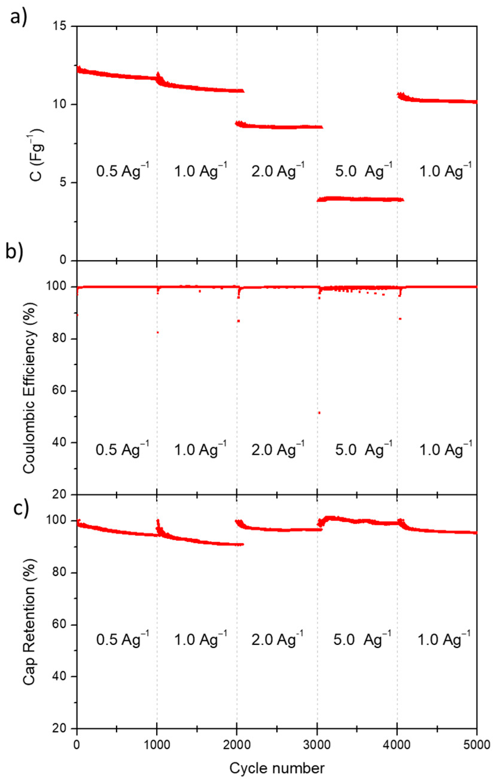
Finally, the stability over long-cycling of the electrolyte LA-H,H was evaluated by performing 5000 charge/discharge cycles at different current densities (1000 cycles for each current density). The evolution of capacitance, coulombic efficiency and capacitance retention over each cycle are reported in
Figure 5.
As shown in
Figure 5a, initial loss of capacitance was observed for the first two groups of cycles, which then stabilized in subsequent cycles.
Figure 5c shows the capacitance retention evaluated by the ratio between the specific capacitance of each cycle and the specific capacitance of the first cycle of each group of cycles. A minimum CR of 94% was obtained in the first thousand cycles at 0.5 Ag
−1. At 1 Ag
−1 the efficiency range dropped to a minimum of 90%, while for the further cycles at 2, 5 and again at 0.5 Ag
−1 the final efficiencies were respectively 96.4%, 98.7% and 95.4%.
Furthermore,
Figure 5b shows the coulombic efficiency over all cycling-groups, which was highly stable and close to 100% for all applied current densities, validating the stability of the electrolytes based on LA-H,H. To ensure a prompt comparison between the achieved results with other electrolyte categories, some EDLCs-electrolytes performances reported in literature are collected in
Table S2.
4. Discussion
The investigation and individuation of new solvents is a relevant issue that has wide implications in different industrial sectors, and, among them, energy storage represents a driving force for their development. In the field of supercapacitors, the most common solvents used for the electrolytes are acetonitrile (ACN) and propylene carbonate (PC).
The use of ACN has several contraindications due to its high vapor pressure (9.71 kPa at 20 °C) and low flash and boiling points. Indeed, according to Regulation (EC) No. 1272/2008 (Classification, Labeling and Packaging (CLP)) it is classified as a “highly flammable liquid and vapor”, and as a volatile organic compound (VOC). Moreover, ACN exhibits acute toxicity for organs and tissues through different types of exposure (skin contact, ingestion, inhalation).
PC is a more user-friendly solvent compared to ACN: it has low vapor pressure (0.006 kPa at 25 °C), high flash and boiling points, and it is classified without hazard statements relative to inhalation or skin exposures. However, the toxicity of organic cyclic carbonates is still under investigation. In recent studies, Strehlau et al. [
58] reported that these compounds can penetrate in vitro the simulated blood-cerebrospinal fluid barrier, and it is therefore assumed that they can reach areas of cerebral interest also in physiological conditions.
Concerning their production, ACN is obtained as a by-product from the synthesis of acrylonitrile (SOHIO process, catalytic ammonium oxidation of propylene), which is performed in gas-phase with metal oxide catalysts using ethylene and/or propylene, ammonia and oxygen [
59]. The PC is mainly prepared by propylene oxide ring-opening in a CO
2 atmosphere under harsh conditions of pressure and temperature [
60,
61]. Therefore, both most used solvents to prepare electrolyte are synthesized from non-renewable feedstock.
In this work we have synthesized a panel of substances (LA-H,H; LA-H,Me; LA-Me,Me) obtainable from renewable sources and with a potentially benign ecotoxicological profile, and we used them for the first time as solvent for non-aqueous EDLCs.
Based on preliminary results, the solvent LA-H,H displayed the highest conductivity (8.5 mScm−1) and was therefore chosen as the best candidate for subsequent characterizations. Two electrolyte-based LA-H,Hs and PCs were prepared with the same conducting salt (TEMABF4) to investigate any differences related to solvent effect. The prepared electrolytes were used to assemble symmetrical EDLC, which were thoroughly characterized by evaluating:
the coulombic efficiency and capacitance retentions by cyclic voltammetry;
the storage performances by charge/discharge GC;
the resistance parameters by potentiostatic impedance spectroscopy;
and the cycling stability over 5000 cycles at different current densities.
The ensemble of results provided by the assembled devices highlights the relevance of the solvent-salt interactions to determine the overall performances. Compared to PC based electrolytes, at 2.6 V LA-H,H/TEMABF4 showed approximately the same coulombic efficiency in the range of 94%–95% and a modest increase of capacitance retention with a high scan rate. The overall storage performances achieved with LA-H,H solvent were adequate for EDLC application (Esp > 10 Whkg−1 and Psp > 20 kWkg−1), and comparable with those achieved with PC/TEMABF4. EIS analysis confirmed small variations among each resistance parameters, and a more prominent difference between the time. Interpreting this behavior with the storage parameters recorded at a high specific current, it is possible to assume that the decrease in specific energy and specific capacity for LA-H,H/TEMABF4 is due to an incomplete formation of the electric double layer, since at high current density the charge time was below the relative time constant. Final stability investigations performed with LA-H,H/TEMABF4 revealed high performance, as capacitance retention (never less than 90% even at high current density) and coulombic efficiency were close to 100% for all the cycles. However, this new electrolyte should be cycled over a longer cycling period (at least 10,000 cycle) to definitively validate its stability in EDLC devices and will be the aim of future developments.
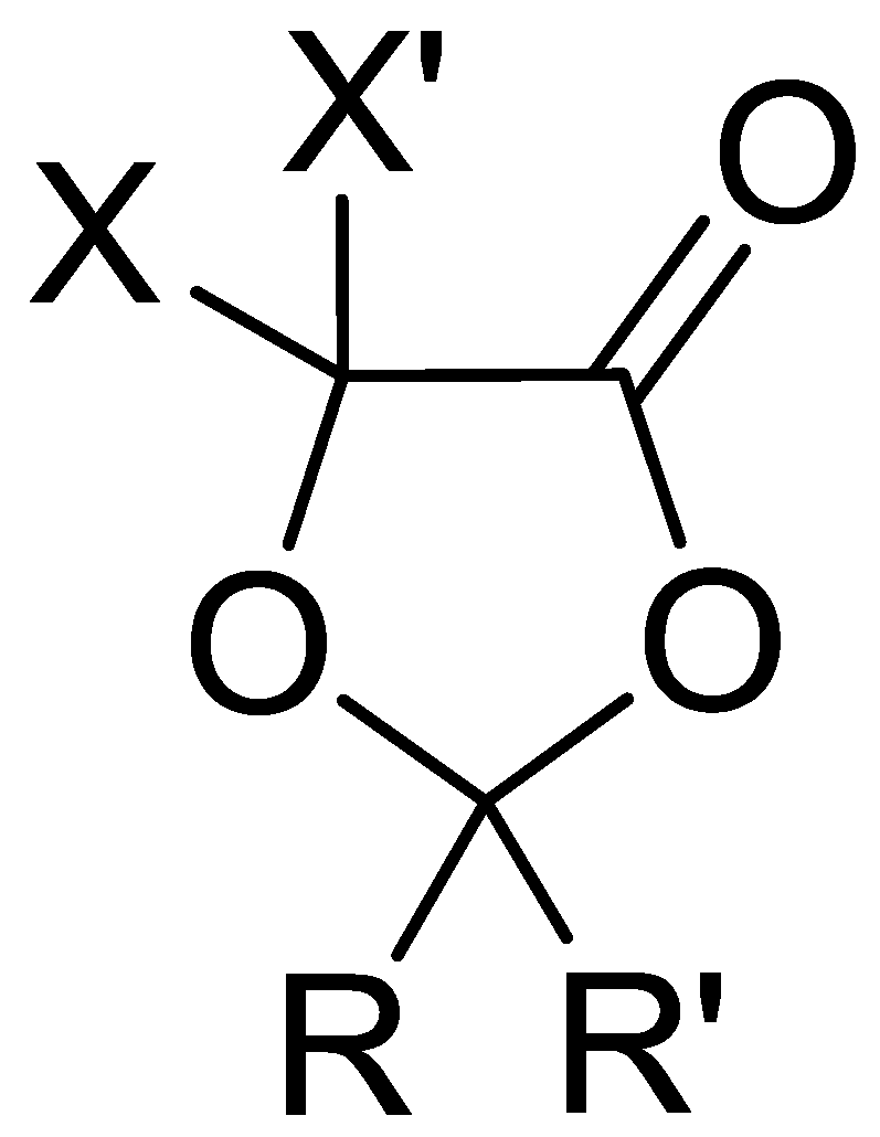
In this work, it was therefore demonstrated that compounds based on the 5-methyl-1,3-dioxolan-4-one scaffold (
Figure 6) are sustainable non-aqueous solvents for applications in energy storage devices. In the future, this class of electrolytes will be extended to other modulable and still unexplored solvents by using other common α-hydroxy acids, such as glycolic, mandelic and 2-hydroxyisobutyric acid, as starting material.
5. Conclusions
Most of the literature articles on non-aqueous electrolytes aims to uniquely increase the EDLC’s performance, often neglecting issues of great importance such as sustainability and safety, and relegating the relevance of these issues only to aqueous electrolytes. In this work we have subverted this concept designing aprotic polar solvents from renewable sources, such as green lactic acid, and investigating their performances.
Within this framework, three dioxolanes with small structural variations in position 2 were synthesized: 2,2,5-trimethyl-1,3-dioxolan-4-one (LA-Me,Me), 2,5-dimethyl-1,3-dioxolan-4-one (LA-H-Me), and 5-methyl-1,3-dioxolan-4-one (LA-H,H). As expected, small structural variations significantly influence their performances, such as conductivity and solvent ability vs TEMABF4, which allowed us to select 5-methyl-1,3-dixolan-4-one for a thorough characterization of the EDLC device. The results demonstrate that the LA-H,H-based electrolyte is suitable for the application, and competitive with the one based on commercial PC. In fact, an operational potential typical of non-aqueous electrolytes (2.6 V, CE ≈ 95%) and adequate storage parameters have been reached (Esp > 10 Whkg−1 and Psp > 20 kWkg−1). This result paves the way for the use of a wide class of solvents based on α-hydroxyacid ketals as sustainable alternatives to those obtained from non-renewable fossil sources. Moreover, thanks to their structural versatility, the room for improvement is still large and further studies will be aimed at increasing performances by finely tuning the solvent-salt combination.


 ,
, 


