Article

Particle-Resolved Computational Fluid Dynamics as the Basis for Thermal Process Intensification of Fixed-Bed Reactors on Multiple Scales

by
Nico Jurtz
1,*,
Urvashi Srivastava
2,
Alireza Attari Moghaddam
3 and
Matthias Kraume
1
1
Chemical & Process Engineering, Technische Universität Berlin, Ackerstr. 76, 13355 Berlin, Germany
2
Clariant Corporation, BU Catalysts, 1600 West Hill Street, Louisville, KY 40210, USA
3
Clariant Produkte (Deutschland) GmbH, Arabellastr. 4a, 81925 Munich, Germany
*
Author to whom correspondence should be addressed.
Energies 2021, 14(10), 2913; https://doi.org/10.3390/en14102913
Submission received: 31 March 2021 / Revised: 11 May 2021 / Accepted: 11 May 2021 / Published: 18 May 2021
(This article belongs to the Special Issue Computational Heat Transfer and Fluid Mechanics)

Abstract

:
Process intensification of catalytic fixed-bed reactors is of vital interest and can be conducted on different length scales, ranging from the molecular scale to the pellet scale to the plant scale. Particle-resolved computational fluid dynamics (CFD) is used to characterize different reactor designs regarding optimized heat transport characteristics on the pellet scale. Packings of cylinders, Raschig rings, four-hole cylinders, and spheres were investigated regarding their impact on bed morphology, fluid dynamics, and heat transport, whereby for the latter particle shape, the influence of macroscopic wall structures on the radial heat transport was also studied. Key performance indicators such as the global heat transfer coefficient and the specific pressure drop were evaluated to compare the thermal performance of the different designs. For plant-scale intensification, effective transport parameters that are needed for simplified pseudo-homogeneous two-dimensional plug flow models were determined from the CFD results, and the accuracy of the simplified modeling approach was judged.

1. Introduction

Fixed-bed reactors are heavily used in the chemical and process industry, especially in the field of heterogeneous catalysis, where there are thousands of individual catalytic fixed-bed reactors with a low tube-to-particle diameter ratio N 10 that are interconnected to tube-bundle reactors. This design decision is the result of optimizing multiple objectives, such as low pressure drop, good radial heat transport, and high active catalytic surface area [1]. Nevertheless, advancing climate change and the shortage of raw materials make more resource- and energy-efficient processes necessary. Here, numerical methods can play a paramount role to develop better designs faster and that are more cost efficient. In the last few years, particle-resolved computational fluid dynamics (CFD) was heavily used by numerous authors to develop process intensification strategies with the focus on the effects on the mesoscopic pellet scale. The range of works extends from investigations of the influence of particle shape on bed morphology and fluid dynamics [2,3,4], heat transport [5,6,7,8], and mass transfer processes [9,10,11,12] to the development of novel reactor concepts, such as packed foams [13,14,15], periodic open-cell structures [16,17,18], finned reactors [19], or the use of random macroscopic wall structures [20,21]. However, particle-resolved CFD is a numerically very demanding method, and its applicability is currently limited to systems with a few thousand particles [22].
When talking about process intensification, however, this can take place at different spatial scales [23], ranging from the molecular scale to the pellet scale to plant scale. On the plant-scale level, process intensification options are process optimization [24,25,26], the development of process integration concepts [1,27,28], and applying dynamic operating conditions [29,30]. Due to the restrictions discussed above, particle-resolved CFD cannot directly be applied for the simulation on the largest scale. For this, process simulation software, e.g., Aspen Plus, gPROMS, or the open-source solution DWSIM, is the more efficient choice. Most often, these software packages use two-dimensional pseudo-homogeneous models to describe fluid dynamics and the heat and mass transfer of fixed-beds. For these kinds of models, the knowledge of effective transport parameters, e.g., the effective viscosity and thermal conductivity, the wall heat transfer coefficient, and the axial dispersion coefficient, is necessary to obtain accurate results. Since those parameters need to lump a series of effects that have their fundamentals on micro- and meso-scale fluid dynamic effects, published data varies greatly [31] and can often only be found for certain reactor designs. This is where particle-resolved CFD comes into play, since it has the potential to act as a data source to derive the effective transport parameters that are needed for a reliable process simulation. Recent publications by Dixon [32] and Moghaddam [33] show encouraging results.
In the scope of this work, we investigated different fixed-bed reactor concepts numerically, using particle-resolved CFD. Besides reactors filled with different particle shapes, namely spheres, cylinders, Raschig rings, and four-hole cylinders, additionally, the impact of macroscopic wall structures was studied for packings of spherical particles. The research focus lied on the quantification and qualitative characterization of their heat transport characteristics. For the sake of reduced complexity and to nail the investigations down to the impact of fluid dynamic effects only, no chemical reactions were considered in the investigated cases. The aim of this study was to:
  • understand the effect of particle shape and macroscopic wall structures on the packing morphology and, with this, the fluid dynamics and heat transport in fixed-beds;
  • quantify improvements in the fixed-bed reactor design that can be achieved, only from a fluid dynamics point of view;
  • increase the phenomenological understanding of fluid dynamics and heat transfer in fixed-bed reactors;
  • show how effective transport parameters, such as the effective thermal conductivity and wall heat transfer coefficient, can be extracted from particle-resolved CFD results. Those parameters can then be used in simplified process simulation models for process intensification on the plant scale.

2. Materials and Methods

In this section, the fundamentals of the numerical models are briefly discussed. For a more detailed description, the reader is referred to literature that explains the fundamentals of CFD [34], particle-resolved CFD [22] and simplified fixed-bed reactor modeling [24,35] in more detail.

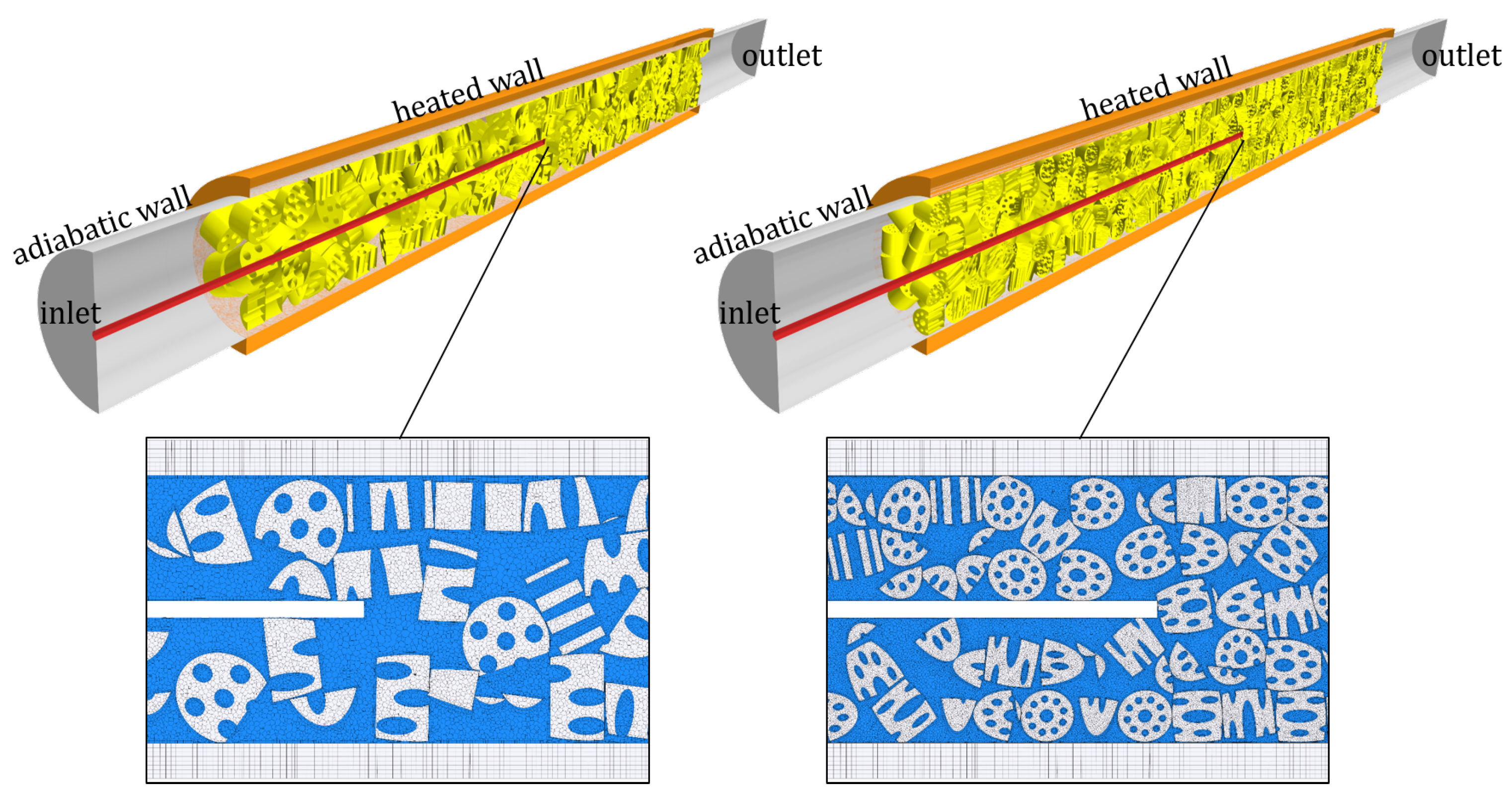
2.1. Particle-Resolved CFD

Particle-resolved CFD is an established numerical method for the simulation of fixed-bed reactors. This CFD-based modeling approach is characterized by a full three-dimensional spatial resolution of all particles and their interstices. The general procedure consists of four fundamental steps: packing generation, CAD generation, meshing, and the CFD simulation itself. For a more detailed discussion about particle-resolved CFD, the interested reader is referred to comprehensive review articles by Dixon et al. [36,37] and Jurtz et al. [22]. A description of all numerical methods used in the scope of this work can be found in Supplementary Material, Sections S1 and S2 attached to the article. The most important material properties and boundary conditions are summarized in Table 1. All numerical simulations were conducted with the commercial CFD tool Simcenter STAR-CCM+ provided by Siemens PLM Software.

2.1.1. Numerical Packing Generation Using DEM

In this study, the discrete element method (DEM) was used to numerically generate random packings of spherical and various cylinder-like particle shapes. For the non-spherical particles, the contact detection algorithm of Feng et al. [39] for cylindrical particles was used. The particle beds of Raschig rings and four-hole cylinders are identical to the ones of the cylinders in terms of particle position and orientation, since they are based on the same DEM simulation results. This means that for particles with inner voids, as Raschig rings and multi-hole cylinders, the effect of the inner voids on the particle dynamics during the filling process was neglected. In our previous studies, it was shown that this was a valid assumption [4]. For all filling simulations, the linear spring contact model was used. An overview of all generated packings is given Figure 1.
The aim of this study was to analyze the impact of particle shape and packing mode on the fluid dynamics and heat transfer. Therefore, fixed-beds filled with different particle shapes were generated, whereby the tube-to-particle diameter ratio was held fixed to a value of N = 5 by setting a constant volumetric sphere-equivalent particle diameter of d p , v = 11 mm and inner tube diameter of D = 55 mm . It is known from previous studies [40,41] that even or odd numbered tube-to-particle diameter ratios can lead to additional heterogeneities in the bed morphology. It was expected that additional morphological heterogeneities would lead to an increase of thermal heterogeneities as well. In order to identify the limitations of the pseudo-homogeneous two-dimensional plug flow model, we decided to benchmark the model for such an extreme case against particle-resolved CFD results. Increasing particles thermal conductivity to extreme values, as recently done by Moghaddam et al. [33], is also an option to increase thermal heterogeneities. However, since in most applications, the ceramic-type catalyst support, which is often porous, is used, which is characterized by a low thermal conductivity ( λ s 0.2 W / ( m K ) ), we decided to not choose that option. A sketch of each investigated particle shape, including its dimensions, is given in Figure 2. The bed height was set to h = 100 d p , v . For each particle shape, two different packing modes were created: a rather loose and a dense bed configuration. To achieve different packing densities, the static friction coefficient was used as a tuning parameter during the DEM simulation. A more detailed description of this method can be found in our previous publications [4,42].
The macroscopic wall structure was generated with a Java macro. Along the reactor length of 1.1 m, on 96 axial stages, fifteen spheres were homogeneously distributed on each stage, whereby the center of mass of each sphere was in coincidence with the tube radius. Subsequently, each sphere was move in the outward direction by a factor of rand ( 0 , 1 ) · d p , v / 2 . Thereafter, all spheres of each stage were rotated with a random angle around the reactor axis, using a rotation angle of rand ( 0 , 1 ) · 2 π . In a final step, the macroscopic wall structure was generated by subtracting all spheres from the reactor tube. The structured tube was afterwards filled with spherical particles, whereby the same simulation parameters and boundary conditions were used as for the smooth wall setup.

2.1.2. Meshing

After the bed generation was completed, the position and orientation of all particles were extracted, and based on these data, a CAD model of the fixed-bed was generated by placing CAD parts of the respective particle shape. Subsequently, the geometry was meshed, whereby the improved local “caps” approach, developed by Eppinger et al. [8], was used to avoid bad cell quality near particle–particle and particle–wall contacts. This enhanced meshing strategy was based on earlier work of the authors [41]. In one of our previous studies, it was proven that this meshing approach not only worked fine for spherical particles, but also for more complex particle shapes such as cylinders, Raschig rings, and multi-holed cylinders [4,43]. It was found that the mesh settings used led to mesh-independent results regarding fluid dynamics and heat transfer [3,10,44]. Recently, Eppinger and Wehinger [8] investigated the impact of the gaps that were introduced between the particles during the meshing process. They found that the gap size had only a marginal effect on bed voidage and pressure drop. However, the authors found that the fluid in the gaps was no longer stagnant if the gap size was increased above a value of 0.01 d p , v , which was the value that was used in the present work. Therefore, a bigger gap size than the one used in this study could negatively affect the accuracy of heat transfer simulations, since an additional thermal resistance would be introduced for the inter-particle heat transfer.
To avoid unwanted inlet and outlet effects, the inlet and outlet faces were extruded a distance of 1 D and 3 D away from the bed, respectively. Two prism layers with a target thickness of 0.025 d p , v were used to capture the fluid dynamic and thermal boundary layer at the particles and the tube wall.

2.1.3. CFD Simulation

The momentum, energy, and turbulence transport equations were solved in a segregated manner (see Section S2). For the sake of reduced complexity and to be able to study the convective and conductive heat transfer without any superposing heat transfer mechanism, the heat transfer simulations were conducted under conditions where radiative heat transfer can be neglected, which was, therefore, not accounted for. Because of this, an inlet temperature of T 0 = 20 ° C and a constant wall temperature of T w = 200 ° C were used along the fixed-bed region.
For all simulations, the SIMPLE-algorithm was used for pressure-velocity coupling, and turbulence was considered through Reynolds-averaged Navier–Stokes (RANS) equations in conjunction with realizable k-ε model-based closures. This turbulence model was successfully used in our previous works [4,8,10,41,43].

2.2. Simplified Heat Transfer Modeling

The class of pseudo-homogeneous models is widely used for the simulation of fixed-bed reactors. Here, the particle scale is not resolved. Instead, all effects are lumped into effective transport parameters. In terms of heat transport, the effective transport parameters needed are either a radially invariant effective thermal conductivity λ eff , r and a wall heat transfer coefficient α w or only a radially varying effective radial thermal conductivity λ eff , r r . The two different concepts are described in the following sections.

2.2.1. Pseudo-Homogeneous λ eff , r - α w Model

The pseudo-homogeneous two-dimensional plug flow heat transfer model under steady-state conditions is described by:
ρ f c p , f u z T z = λ eff , r 2 T r 2 + 1 r T r + λ eff , z 2 T z 2 ,
whereas the following boundary conditions are used:
λ eff , r T r = α w T T w           at r = R
T r = 0           at r = 0
T = T 0           at z = 0
T z = 0           at z = L .
Here, u z = u 0 / ε is the constant interstitial velocity, ρ f the fluid density, and c p , f the specific heat of the fluid. The λ eff , r - α w model lumps all radial heat transfer mechanisms into a constant effective radial thermal conductivity λ eff , r . The steep temperature drop at the tube walls is modeled by the introduction of an artificial wall heat transfer coefficient α w , using Equation (2). The thermal conductivity in axial direction can be assumed to be equal to the stagnant effective thermal conductivity λ eff , z = λ eff , r 0 , or it can be neglected if the system is dominated by convective effects. The model itself has been critically discussed by many authors [31,45,46], but nevertheless widely spread due to its simplistic nature.
It was found by Yagi and Kunii [47] that the radial effective thermal conductivity can be expressed as:
λ eff , r λ f = λ eff , r 0 λ f + 1 P e f , r P r R e p .
The first term on the right-hand side is the effective radial thermal conductivity of the stagnant bed. A huge number of correlations exists to determine λ eff , r 0 , which have been reviewed by van Antwerpen et al. [48]. Based on a unit cell approach, Zehner and Schlünder [49] derived the following correlation that is widely used:
λ eff , r 0 λ f = 1 1 1 ε + 2 1 ε 1 κ 1 B · 1 κ 1 B 1 κ 1 B 2 ln 1 κ 1 B B + 1 2 B 1 1 κ 1 B
Here, κ is the ratio of solid to fluid thermal conductivity and B is the deformation parameter, which is related to the void fraction by B = 1.25 1 ε / ε 10 / 9 . The correlation can be further extended by incorporating secondary effects like radiative heat transfer or the effect of particle–particle contacts on the heat transfer. For a more detailed description, the interested reader is referred to the work of Tsotsas [50] and van Antwerpen et al. [48].
For the heat transfer coefficient at the wall, Yagi and Kunii [51] proposed the following correlation for N u w = α w d p , v / λ f :
N u w = N u w 0 + 1 1 / N u w * + 1 / N u m ,
using:
N u m = 0.054 P r R e p
N u w * = 0.3 P r 1 / 3 R e p 3 / 4
N u w 0 = 1.3 + 5 N λ eff , r 0 λ f .
Nilles and Martin [52,53] developed the following correlation that is widely used:
N u w = 1.3 + 5 N λ eff , r 0 λ f + 0.19 P r 1 / 3 R e p 3 / 4 .
According to Dixon [31] two methods are commonly used to determine λ eff , r and α w . The first option is a parameter estimation done by conducting an optimization study based on the λ eff , r - α w model, whereas the objective is to minimize the sum of squared error regarding the radial temperature profile at one or more axial positions. Alternatively, the method described by Wakau and Kaguei [54] can be used. This method is based on the approximate solution of the pseudo-homogeneous λ eff , r - α w model and allows determining λ eff , r and α w from the axial temperature profile in the core of the bed and the average outlet temperature. Both can easily be extracted from the particle-resolved simulation results.
The latter method was used in this study and presented in great detail by Wakao and Kaguei [54]. By neglecting the axial thermal conductivity, the analytical solution of Equation (1) is:
T w T T w T 0 = 2 n = 1 J 0 2 a n r / D exp a n 2 y a n 1 + a n / B i 2 J 1 a n .
Here, r is the radial position and B i the Biot number B i = α w D 2 λ eff , r . a n is the n-th root of the following equations that include the Bessel function of the first kind and zeroth-order J 0 and the first kind and first-order J 1 :
B i J 0 a n = a n J 1 a n .
The parameter y is expressed by:
y = λ eff , r z ρ f u z c p , f D / 2 2 ,
whereas z is the axial position, ρ f the fluid density, and c p , f its specific heat. Deep in the bed, when y 0.2 , the first term in the series of Equation (13) becomes predominant, leading to:
T w T T w T 0 = 2 J 0 2 a 1 r / D exp a 1 2 y a 1 1 + a 1 / B i 2 J 1 a 1 .
with:
B i J 0 a 1 = a 1 J 1 a 1 .
In the center of the bed ( r = 0 and T = T core ) , Equation (16) is reduced to:
T w T core z T w T 0 = 2 exp a 1 2 y a 1 1 + a 1 / B i 2 J 1 a 1 .
If Equation (18) is logarithmized, it gives:
ln T w T core z T w T 0 = a 1 2 λ eff , r ρ f u z c p , f D / 2 2 z + ln 2 a 1 1 + a 1 / B i 2 J 1 a 1 .
It was shown by Wakao and Kaguei [54] that the following relationship for the average outlet temperature T m is valid for a reasonably large axial position:
T w T m T w T core = 2 J 1 a 1 a 1 .
From Equation (20), a 1 can be solved iteratively, and λ eff , r can be calculated from the slope of Equation (19), subsequently. The wall heat transfer coefficient can either be determined from the intercept of Equation (19) or from Equation (17). The latter method was promoted by Wakao and Kaguei [54], since the authors argued that α w is very sensitive to slight changes of the intercept.
Both methods were tested during this study. A sensitivity test was conducted based on the particle-resolved CFD results for a packing of spherical particles at R e p = 100 . The sensitivity analysis of α w and λ eff , r towards the accounted temperature range was conducted, whereas the range of Θ core = T core T 0 / T w T 0 was varied as follows: { Θ core R : 0.05 Θ core 0.4 0.6 Θ core 0.95 } . It was found that λ eff , r had a relative standard deviation (RSD) of ± 6 % . Then, from the intercept of Equation (19) calculated, the values of α w had a very low RSD of ± 3 % , while the suggested method of Wakao and Kaguei increased the RSD to ± 15 % , which was in contrast to the authors’ argumentation. Nevertheless, a huge discrepancy in α w was found: the values of the intercept-method were up to three times lower in comparison to the values determined from Equation (17). A comparison of particle-resolved CFD results against the results of the two-dimensional plug flow model in terms of axial and radial temperature profiles revealed that the temperature profiles were mispredicted if the intercept method was used, while the method promoted by Wakao and Kaguei led to reasonable results. Therefore, as Wakao and Kaguei did, we also highly recommend calculating α w from Equation (17) instead of the intercept of Equation (19). To evaluate λ eff , r and α w , the axial temperature profile was limited to 0.2 Θ 0.8 in this work.

2.2.2. Pseudo-Homogeneous λ eff , r r - u z r Model

Instead of describing the additional thermal resistance close to the wall with a heat transfer coefficient, a radially varying effective radial thermal conductivity can be introduced. Furthermore, the radial variations of the interstitial velocity and effective axial thermal conductivity can also be considered. With this, Equation (1) is modified as follows:
ρ f c p , f u z r T z = 1 r r λ eff , r r r T r + λ eff , z r 2 T z 2 .
In this case, the artificial boundary condition described in Equation (2) vanishes and is replaced by the following Dirichlet boundary condition:
T = T w           at r = R .
As reviewed by Dixon [31], multiple models exist to determine λ eff , r r . Most often, the reactor is split into two regions to characterize the heat transfer in the near-wall and the bulk region separately. The models reported in the literature vary in their definition of the extent of each region and the description of λ eff , r r = f r . Ahmed and Fahien [55] defined the wall region to be 2 d p , v thick and used a cubic dependency for λ eff , r r in the bulk and a linear decrease in the wall region. They used the correlations of Argo and Smith [56] in combination with correlations for the radial void fraction distribution to obtain the necessary values of λ eff , r in the center of the bed, at the tube wall, and at the interface of both regions. Contrary, Gunn et al. [57,58,59] used a constant value for λ eff , r in the bulk region and assumed a quadratic dependency of T r in the wall region. They defined the wall region to be 0.3 d p , v thick. Smirnov et al. [60] defined a wall thickness that depended on bed voidage and particle specific surface area. They used a constant effective thermal conductivity in the bulk region and a linear dependency close to the wall. Winterberg et al. [61] proposed a Reynolds number-dependent thickness of the wall region. In the core region, a constant λ eff , r was assumed, which decreased in the wall region, using a power-law approach that depends on the Reynolds number, Péclet number, and three more parameters. Recently, Pietschak et al. [62] reviewed several heat transfer correlations and found the correlation of Winterberg et al. [61] to be superior, especially if axial and radial variations of fluid properties were considered. Pietschak et al. [63] proposed a new correlation that accounted for the drop of λ eff , r close to the wall, but without the need to introduce a discontinuity at the interface of the near wall and the bulk region. The authors correlated λ eff , r r = f ρ f , c p , f , d p , v , ε 0 , ε w , ε r , u 0 r and added the cross-mixing factor and an exponent as additional parameters. The radial velocity and void fraction profiles were taken from additional correlation, but the needed data could potentially also be derived from particle-resolved simulations, as recently shown by Dixon [32].
In this work, the correlation of Winterberg et al. [61]:
λ eff , r r = λ eff , r 0 + u 0 , c d p , v ρ f c p , f K w · f R r ,
using:
f R r = R r k f , w d p , v n f , s if 0 < R r < k f , w d p , v 1 if k f , w d p , v < R r < R ,
was used as the basis to determine λ eff , r r . In Equation (23), K w is the cross-mixing factor that describes the relationship between effective thermal conductivity, particle shape, and flow velocity deep in the bed. The cut-off parameter k f , w in Equation (24) sets the dimensionless wall distance, after which the constant thermal conductivity, which was assumed in the core region, drops towards the wall. The exponent n f , s describes the curvature of the damping function close to the wall.
To determine the parameters above, the circumferentially averaged radial temperature profiles in the interval z =   0.1 : 0.1 : 1.1 were extracted from the particle-resolved CFD simulations for the simulation with R e p 500 . For the lowest investigated Reynolds number of R e p = 100 , the radial temperature gradients flattened out quickly. Therefore, in this case, only the temperature profiles in the range of z =   0.1 : 0.1 : 0.3 were considered. Based on the model described by Equation (21), a parameter optimization study was conducted, using the Nelder–Mead algorithm, while the objective was to minimize the sum of least squares of the difference of the radial temperature profiles between the simplified model and the particle-resolved results. In total, a number of 1100 ( R e p 500 ) and 300 ( R e p = 100 ) data points were available for the optimization task for each operating condition.

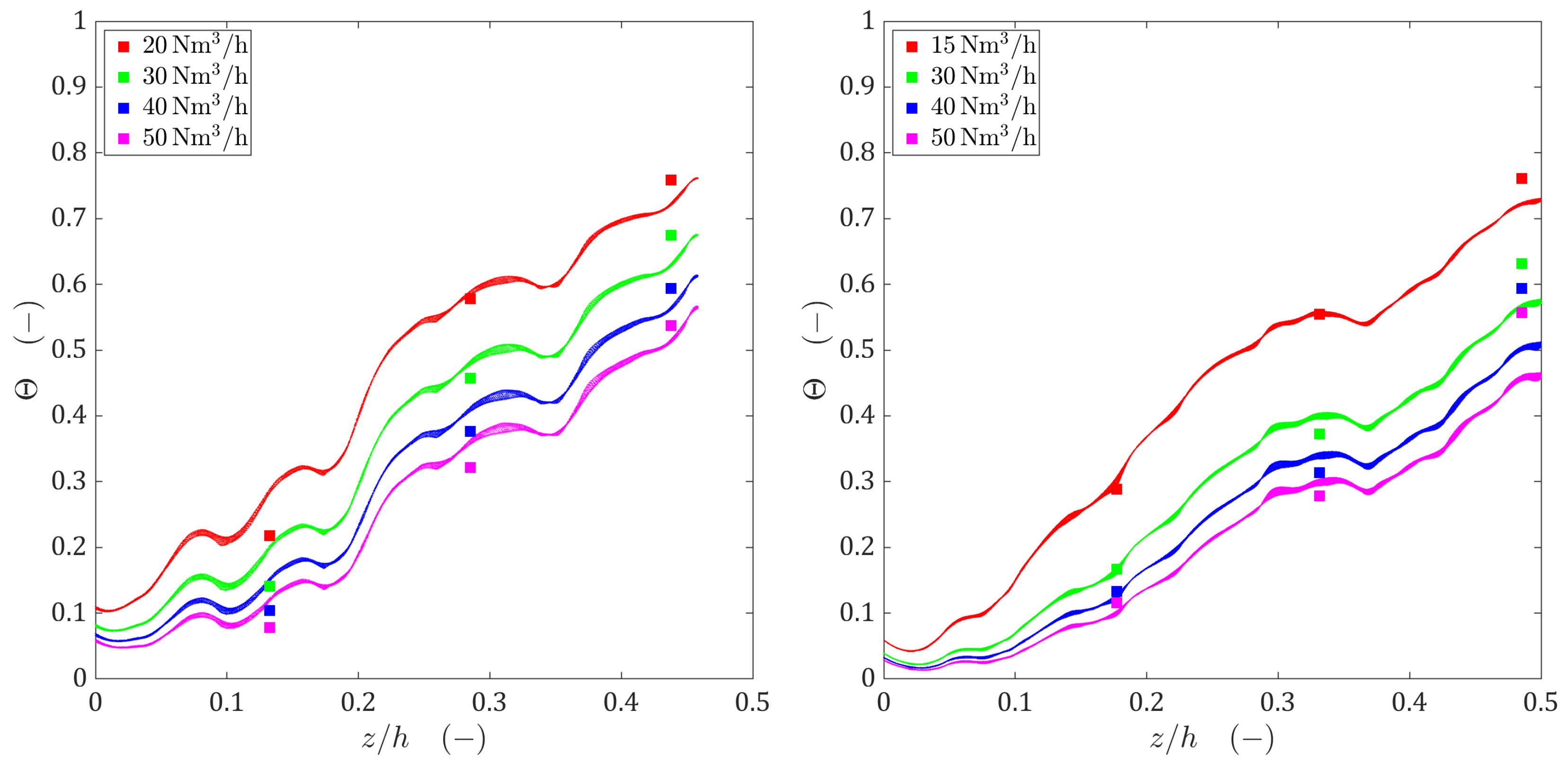
3. Heat Transfer Validation

Experimental validation data for axial or radial temperature profiles are scarce and hard to find. Nevertheless, Wehinger et al. [3] and Dong et al. [6] were able to prove the accuracy of the particle-resolved CFD approach, especially in combination with the local “caps” meshing strategy, in terms of axial and radial temperature profiles.
Based on experimental data that were provided by Clariant International Ltd., a validation study was conducted in this work to confirm the reliability of particle-resolved CFD also under industrially relevant conditions (T > 1000 °C). The experimental setup consisted of a hot box, fired with an electrical furnace, and a single reformer tube with an inner diameter of 0.1016 m and a bed height of 1 m. With thermocouples, placed at the outside of the reformer tube, the axial profile of the outer wall temperature was measured. The temperature in the center of one of the packed reformer tubes was measured with a 0.25″ standard 316 SS axial thermowell until an axial distance of approximately 0.5 m. The thermocouples used were of type K, with an accuracy of ±1.5 °C or ±0.4%, whichever was greater. In the scope of this study, two different particle shapes, a tablet-like cylinder with six holes (33 × 18 mm) and an almost equilateral cylinder with ten holes (19 × 16 mm), were investigated.
The experimental setup was replicated numerically, whereas special emphasis was given to meet the particle count that was determined in the experiments. To achieve this, particle static friction coefficients were calibrated, as described by Jurtz et al. [4,42]. Since the tube thickness was relatively big, not only the fluid and the particles, but also the reformer tube itself were spatially discretized. While a fully conformal contact interface was used for the particle-fluid interface, for the sake of reduced cell count, the tube-fluid interface was performed as a non-conformal mapped contact interface. An overview of the investigated setups, including snippets of the resulting meshes, can be seen in Figure 3. Preliminary studies showed that the thermowell not only affected the flow field significantly, as recently discussed by Dixon and Wu [64]. It was found that the heat conduction through the thermowell could not be neglected, since it significantly affected the temperature distribution in the vicinity of the measuring device. To consider for heat conduction in the thermowell, a three-dimensional shell model was used that solved for the lateral conductive heat transport and modeled the heat transport in the face normal direction via the assumption of a constant temperature gradient. The radiative heat transport was considered using a surface-to-surface radiation model as done by Wehinger at al. [7] recently.
The experimentally measured temperature distribution on the outer side of the reformer tubes was applied as a spatially varying fixed temperature boundary condition at the outer tube surface. The inlet temperature, according to experimental data, was set to 560 °C and the operating pressure to 1.5 barg. Nitrogen was used as the working fluid, whereas the ideal gas equation of state was used. The fluid viscosity and thermal conductivity were calculated using the Chapman–Enskog model. Inlet flow rates were varied between 15 and 50 Nm3/h. Particles’ thermal conductivity was set to 0.25 W/(m K), whereas for the tube and thermowell, the following function, derived from the spec sheet, was used: λ s W / ( m K ) = 8.195 · exp 1.188 · 10 3 · T . The emissivity was set to 0.75 for the particles surface and to 0.6 for the inner reformer tube and the thermowell.
The simulation results are given in Figure 4 in terms of the axial profiles of the dimensionless temperature Θ = T T 0 / T ref T 0 , whereas T ref is the furnace temperature. The numerical data are presented as a scattered cloud of small symbols to also visualize the temperature variation in the circumferential direction. It can be seen that due to the conductive heat transport within the solid of the thermowell, temperature variations in circumferential direction were low. Without considering this heat transfer mechanism, temperature differences of over 50 K were found (see Section S3), which indicated that the measuring device not only affected the fluid dynamics, but also the measured temperature field significantly. This strengthened the argument that the use of high-fidelity numerical methods can improve the accuracy of determining effective heat transfer parameters significantly. Deep in the bed, an excellent agreement could be found between the predicted and measured temperatures for the six-hole tablets. Only for z / h 0.1 , some deviations were found. However, if one considers the obvious impact of the heterogeneous bed morphology on the axial temperature profile, the accuracy was still acceptable. For the 10-hole cylinders, the experimental temperature profile was hit almost perfectly for z / h 0.35 . For a flow rate of 15 N m3/h, also deep in the bed, a good agreement with the experimental data was found. However, at higher flow rates, for z / h 0.5 , the simulations results were far off. The reason for this could not be identified, but the fact that the experimental data showed an increase of the axial temperature gradient at higher bed depths for high flow rates was suspicious and may indicate that the temperature sensors were damaged under the harsh operating conditions. Similar problems have been noted by other authors [31] and illustrate the challenges associated with experimental temperature measurements in fixed beds. A possible re-ordering of particles at the tip of the thermowell during operation might also be a possible reason for the deviations observed.

4. Results and Discussion

The heat transport in fixed-bed reactors is strongly coupled to fluid dynamics effects that are induced by the heterogeneous bed morphology. Therefore, in the first part, the bed morphology and fluid dynamics of all generated packings were investigated. Afterwards, the different configurations were compared with regard to their thermal performance. The global heat transfer coefficient U = Q ˙ w / A w Δ log T , using Δ log T =   T out T in / log T w T in / T w T out , was used to compare the different designs, whereby U was evaluated for an axial threshold of the reactor that fulfilled the criterion 0.0 Θ core 0.8 . In the last part, the simulation results were used to determine effective thermal transport parameters that are commonly needed for the pseudo-homogenous two-dimensional plug-flow model. The results were compared against particle-resolved CFD results to understand the reliability of simplified models. A summary of the most important results and simulation parameters is given in Table 2. A schematic drawing of the setup is presented in Figure 5.

4.1. Bed Morphology and Fluid Dynamics

Already, the first visual impression of the generated packings that was given in Figure 1 showed the strong impact that the packing mode had on the particle arrangement. This can best be seen for spherical and cylindrical particles. While for the loose packing configuration, although the confining walls exerted an ordering effect on the particles, to some extent, random arrangement of the particles close to the wall can be seen, the compacted beds were characterized by a high degree of order. Especially the spherical particles tended to build band-like structures at the wall, whereas cylindrical particles built stacked structures and were mostly oriented parallel or perpendicular to the wall. From a fluid dynamics and reaction engineering point of view, the most important effect was the significant reduction in bed voidage that was caused by bed densification. By this, the pressure drop, local flow phenomena, hydraulic residence time, and the active catalytic surface area per reactor volume were significantly affected. The evaluated bed voidage, listed in Table 2, shows that for spherical particles, the bed voidage was reduced by 10%. An extreme reduction of 20% was found for cylindrical particles. For particles with inner voids, like rings and four-hole cylinders, the effect was less pronounced, giving a drop of 10% and 6%, respectively. However, this reduced impact was only a result of the overall higher bed voidage for these particles. For the configuration of spherical particles in the reactor with macroscopic random wall structures, the densification-induced reduction of bed voidage was 11%, which was similar to the reactor with plain walls.
The axial and radial void fraction profiles were good resources to understand the packing morphology of the different designs. Strong and regular oscillations are indicators of ordered particle arrangements and a loss of randomness in the system, whereas low non-regular fluctuations in bed voidage point towards an increasing randomness of the particle arrangement. For an ideally random packing arrangement, the void fraction profile should end in a constant value. Distinct peaks in the void fraction profile are indicators of additional voids that are a result of a non-appropriate filling strategy, which leads to jamming of particles. The axial void fraction profiles of all investigated packings are given in Figure 6. Since the bed rested on a bottom plate, the lowest layers of particles experienced a certain ordering effect, which was induced by the adjacent wall. For spherical particles, only a point contact was possible between the particles and the bottom plate, leading to a value of ε = 1 at z / d p = 0 . Particles of the cylindrical shape type may have a point, line, or face contact with the wall. If face contacts are present, it is possible that ε < 1 at z / d p = 0 . However, for most of the investigated packing, it can be seen that the ordering effect of the bottom plate led to regular oscillations in the void fraction that flattened out after a distance of 3–dp and ended up in random oscillations of lower magnitude, indicating a stochastic axial distribution of the particles. The only exceptions were the compacted packing of spherical particles and the loose packing of spheres in the reactor with macroscopic wall structures. For the dense packing of spheres, regular oscillations were observed between 0 z / d p 22 . This indicated a pronounced layer formation in the bottom part of the reactor. In the remaining part of the reactor as well, regular oscillations were observed, albeit to a lesser extent. In the wall structured reactor, high fluctuations were observed that suddenly appeared and flattened out. A probable reason for this was jamming of particles during the filling process that led to additional voids. This hypothesis was strengthened by the fact that this effect vanished for the densified packing.
Of fundamental interest for the understanding of the fluid dynamics are the radial void fraction profiles and the radial profiles of the circumferentially averaged axial velocity, given in Figure 7. Here, the axial velocity was normalized to the local interstitial velocity u 0 / ε r . With the exception of the structured wall reactor, for all particle shapes, directly at the wall, a void fraction of ε = 1 was found due to the presence of point and/or line contacts, only. For spherical particles, a first minimum in the void fraction was reached after the distance of one particle radius away from the wall, indicating that the majority of spheres were in direct contact with the wall, forming a closed particle layer. Furthermore, local minima and maxima occurred at positions corresponding to multiples of the particle radius, whereas the oscillations slightly decreased. The global minimum of the void fraction was located in the center of the bed, indicating that an almost stacked arrangement of spheres was present. This was the result of odd tube-to-particle diameter ratios [40,41]. A strong correlation could be found between the void fraction and the velocity profile. Close to the wall, the velocity reached its maximum, known as the wall channeling effect. The position of further minima and maxima corresponded directly to the position where high/low void fractions were found. While the minima of axial velocity did not change with varying R e p , the maxima increased slightly in the center of the bed if R e p was lowered. This effect could be attributed to the gas expansion due to heating and to the decreasing wall effect if R e p was lowered. The center of the bed was almost completely blocked for the flow. The above findings were also valid for the densified packing of spheres; however, the effects were even more pronounced, resulting in a complete blockage of flow paths at r * =   R r / d p =   0.5 , 1.5 , 2.5 , and strong channeling was observed at r * =   0.1 , 1.0 , 2.0 , whereas for R e p 500 , the strongest channeling was not found at the wall, but at r * = 2.0 , which is very uncommon.
For cylindrical particles, the trend was similar as for spheres; however, the minima/ maxima in the void fraction and velocity were slightly shifted towards the bed center, which indicated that some particles were diagonally aligned. For the densified packing, the minima/maxima were found at multiples of the particle radius, which was a result of the particles’ preferred parallel/orthogonal alignment. In contrast to the packings of spheres, where the wall channeling was almost independent of R e p , for cylindrical particles, the wall channeling effect increased significantly if R e p was raised. This effect became very dominant for the compacted packing. The void fraction profiles for Raschig rings and four-hole cylinders looked pretty complex; nevertheless, especially for r * < 1 , the inner voids of the particles were clearly reflected by corresponding additional maxima in the void fraction. However, no maxima in velocity could be found at void fraction maxima that corresponded to inner voids. This indicated that the flow through the inner particle voids was partially blocked, which might be because of an orthogonal particle alignment. Overall, the void fraction and velocity oscillations were less pronounced for those particle shapes, but heterogeneities increased if the beds were compacted. Similar to cylindrical particles, the wall channeling effect increased with R e p and became more pronounced for densified packings.
The use of macroscopic random wall structures for packings of spherical particles changed the void fraction and velocity profiles significantly. Due to the presence of the wall structure, the void fraction at the wall fell to a value of ε 0.56 . As a result, the wall channeling effect was hindered, and fluctuations in the void fraction and velocity were qualitatively more comparable to the ones of Raschig rings than spheres. The densification of the bed led to slightly more pronounced minima and maxima; however, this effect was not as distinct as for spherical particles in a smooth walled reactor.

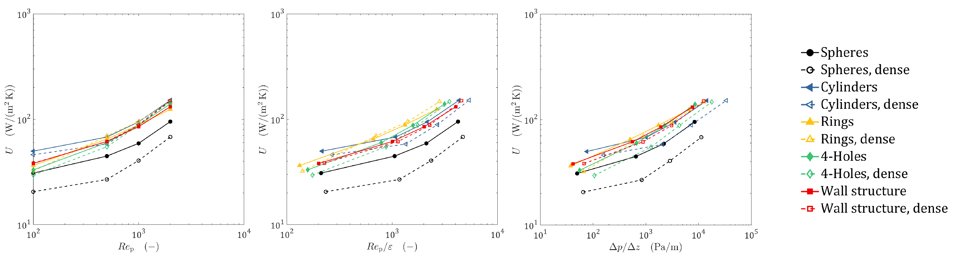
4.2. Heat Transfer Characteristic

A fair comparison of the thermal performance of different reactor concepts always depends on the process boundary conditions that are set. Figure 8 shows the global heat transfer coefficient U as a function of different parameters. Re-fitting of an existing unit that is integrated in a complex production process can lead to the necessity of keeping the throughput constant, which is equivalent to keeping R e p invariant. In this case, especially at low R e p , cylindrical particles showed the most beneficial heat transfer characteristic, followed by the wall-structured reactor, Raschig rings, and four-hole cylinders. Spherical particles performed worst over the complete range of investigated R e p . At high R e p , cylindrical particles still performed best; however, rings, four-hole cylinders, and the reactor with wall structures were close. For spheres, cylinders, and four-hole cylinders, U decreased if the packings were compacted. This is of special interest, since in industrial applications, most often, densified packings are used to ensure the same pressure drop in the different tubes of the tube bundle reactor. Interestingly the effect was less pronounced for Raschig rings and the wall-structured reactor. At high R e p , even a slight increase in thermal performance could be seen for those reactor types. In general, the performance gain induced by macroscopic random wall structures was significant.
Another valid process boundary condition can be the necessity of keeping the hydraulic residence time invariant. In this case, R e p / ε needs to be kept constant. Under this constraint, Raschig rings and four-hole cylinders performed best for moderate to high R e p , followed by cylinders and the wall-structured reactor. For the lowest investigated R e p , again, cylindrical particles seemed to perform slightly better than rings.
If a new plant is built and process-driven constraints are low, the most energy efficient particle shape might be an appropriate choice. In this case, the specific pressure drop Δ p / Δ z can be one parameter that should be kept constant when comparing different designs. In this case, Raschig rings, the wall-structured reactor, and cylinders performed best. The comparison of the designs from this energetic point of view showed that bed densification led to a less energy-efficient thermal performance, whereas this effect was less pronounced for Raschig rings and the reactor with macroscopic wall structures.

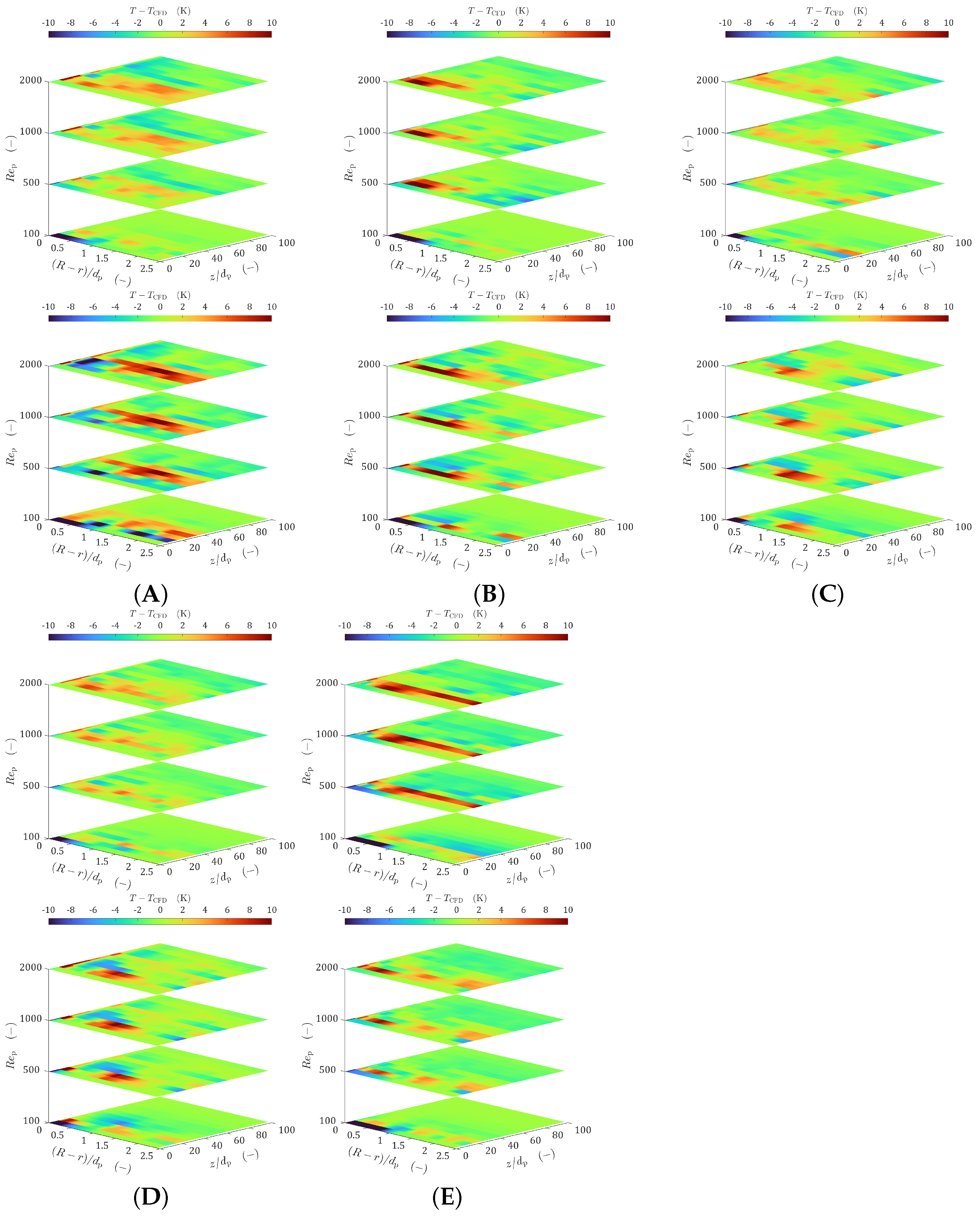
4.3. Effective Thermal Transport Properties

As discussed, particle-resolved CFD is a valuable tool to support process intensification on the meso-scale level, e.g., by finding optimized particle shapes [4,10,11,12] or new reactor concepts, e.g., by applying macroscopic wall structures [20,21] or using internals [19]. However, for process intensification on a macroscopic scale, e.g., by running plants under dynamic operation conditions, developing process integration strategies, or doing plant optimization, different numerical tools are necessary. Process simulation platforms often use pseudo-homogeneous two-dimensional plug flow models. Depending on the class of model used, certain effective transport parameters are needed, which are often not known. In this section, methods are presented for how those parameters can be extracted from particle-resolved CFD results.

4.3.1. λ eff , r - α w Model

Although its limitations are well known [31], the λ eff , r - α w model is still widely spread, due to its efficiency and simple implementation. Here, the radial heat transport was characterized by the wall heat transfer coefficient α w and the effective radial thermal conductivity λ eff , r , which was assumed to be uniform everywhere in the reactor. By extracting the axial core temperature profile and average inlet/outlet temperatures from the CFD simulations, both parameters were determined by using Equations (17), (19), and (20). The results are summarized in Table 2. The parameters were then used to calculate the temperature fields by using the pseudo-homogeneous model described by Equation (1) in conjunction with the boundary condition in Equation (2).
A one-to-one comparison of all investigated cases in terms of radial temperature profiles at different axial positions is provided in Supplementary Material, Section S4. A condensed visualization of the results is given in Figure 9. Here, the deviations of the circumferentially averaged temperature fields, predicted by the pseudo-homogeneous model, are given in relation to the particle-resolved CFD results. Deep red and deep blue colors indicate that the deviation was above or below 10 K. This critical cut-off temperature was chosen, motivated by the rule of van’t Hoff, saying that the speed of a chemical reaction doubles to triples itself when the temperature is raised by 10 K [65]. The characteristic temperature drop at the wall that was a result of α w can only hardly be seen in Figure 9. The reader is referred to the radial temperature profiles given in Section S4. It can be seen that the temperatures close to the wall (r* ≤ 0.2–0.4) were systematically underpredicted by the simplified model. This drawback is well known and deeply discussed by many authors [31]. Furthermore, the model was not able to capture morphological and fluid dynamic heterogeneities, which led to step-like temperature profiles, as can be seen best for the radial temperature profiles of the dense spherical packing. Recently, this was also found by Moghaddam et al. [33], who introduced heterogeneities by increasing the solid thermal conductivity. Besides those systematic errors, the deviation in relation to the CFD results was relatively low for the majority of cases. For all investigated designs, the deviation was less than 5 K for the rear part of the reactor ( z / d p 40 ). The threshold of 10 K was mostly exceeded in the entry zone ( z / d p 20 ). Overall, there seemed to be a trend that deviations increased if R e p was raised. The method seemed to work equally well for loose and densified packings with a slight trend towards less deviations for dense beds. Considering the numerical effort that the simplified model needed in comparison to the particle-resolved CFD simulation, which was ≈10 s compared to ≈24 h, the accuracy was still remarkable.

4.3.2. λ eff , r r -Model

The obvious drawback of the λ eff , r - α w model, that the additional near wall thermal resistance is only captured with an artificial temperature drop directly at the reactor wall, can be circumvented by using a radially varying effective radial thermal conductivity. In this work, the correlation of Winterberg [61] (see Equation (23)) was used as the basis to determine the effective radial thermal conductivity. The three necessary parameters of the Winterberg correlation were determined by conducting a parameter optimization study. The basis of this study was the transport equation described by Equation (21). A summary of the optimized model parameters, including the mean squared error M S E , is given in Table 2.
The comparison of the radial temperature profiles for different axial positions can be found in Supplementary Material, Section S5. The spatially resolved deviations between the simplified model and the CFD results are given in Figure 10. It is obvious that in comparison to the results of the λ eff , r - α w model, the accuracy was significantly improved. The temperature close to the reactor wall was predicted with a high degree of accuracy by the model. Only sporadically, the temperatures were overestimated by more than 10 K in the vicinity of the wall, whereby the location was mostly limited to the entry zone ( z / d p 20 ). A direct comparison of the λ eff , r - α w model and the λ eff , r r model in relation to the CFD results is given in Figure 11 for the loose packing of Raschig rings at R e p = 1000 , showing the superior accuracy of the λ eff , r r model, especially close to the wall. Deep in the bed, deviations outside of the 10 K threshold were mostly found for packings that were characterized by a higher degree of morphological heterogeneity, like the packings of cylindrical particles, the dense bed of spheres, and the loose packing of spheres in the reactor with a random wall structure. While the former configurations were characterized by strong variations in the radial void fraction distribution, the latter showed big fluctuations in the axial void fraction profile. Bigger deviations were mostly limited to the entry zone, indicating that thermal entrance effects, which were not resolved by an axially invariant λ eff , r r , might be the reason for this. In contrast to the λ eff , r - α w model, the deviations did not seem to increase if R e p was raised. Since the Winterberg correlation did not explicitly consider local variations in the void fraction or axial velocity, it was, similar to the λ eff , r - α w model, not able to capture the step-like effects of the temperature profiles.

5. Conclusions

In this work, it was shown in which way the particle-resolved simulation of fixed-bed reactors can play a central role in the process the intensification of this reactor type. After a brief validation study, showing that also under harsh industrial conditions, particle-resolved CFD was able to predict the temperature field accurately, the heat transfer characteristics of different particle designs were investigated. The studied designs differed in the used particle shape and the bed density. The results showed that heterogeneities in radial void fraction distribution and axial velocity increased, if packings were compacted. As a result, the overall heat transfer coefficient U decreased for most particle shapes. Although the wall channeling effect was most pronounced for the fixed-beds of cylindrical particles, it was found that this particle shape was among the most efficient, with respect to U. Furthermore, a novel reactor tube design that used random macroscopic wall structures was investigated. For packings of spherical particles, it was found that macroscopic random wall structures can significantly decrease morphological heterogeneities, leading to a significantly better heat transfer characteristic. Taking into account various process-related boundary conditions, cylindrical particles, Raschig rings, and wall-structured reactors were identified as the most promising concepts to intensify the radial heat transport.
Methods were presented to determine effective thermal transport parameters, which are needed for simplified pseudo-homogeneous models, from the particle-resolved CFD results. Depending on the degree of morphologically induced heterogeneities, an excellent to fair agreement was found for the λ eff , r - α w model in comparison to the CFD results, whereas deviations became bigger if the morphology was more heterogeneous. The known problem of underestimated temperatures close to the reactor tube, as one of the biggest drawbacks of this model, was confirmed. To circumvent this problem, parameter optimization studies, based on the Winterberg correlation, were performed to predict the radially varying effective radial thermal conductivity, which was needed for the λ eff , r r model. A very good agreement regarding the radial temperature profiles was found between the λ eff , r r model and the particle-resolved CFD results. In comparison to the λ eff , r - α w model, the λ eff , r r model showed its superior accuracy close to the reactor wall. Nevertheless, it was found that both pseudo-homogeneous models became less accurate if step-like temperature profiles, which were a either a result of morphological heterogeneities or a high particle solid thermal conductivity, were present.
In terms of process intensification, this work showed that particle-resolved CFD can either directly be used to study improvements on the meso-scale through:
  • studying the impact of particle shape, internals, or reactor tube design on the performance;
  • investigating the effect of operating conditions and physical properties;
  • testing of novel reactor tube concepts, e.g., reactors with random macroscopic wall structures or heat fins;
  • identifying local phenomena as hot/cold spot formation or catalyst poisoning;
or as a reliable source for parameters, and correlations of those, that are needed for process simulation. This allows a more reliable analysis of process intensification by studying:
  • dynamic operating conditions;
  • process integration concepts;
  • conducting process design optimization.

Supplementary Materials

The following are available online at https://www.mdpi.com/article/10.3390/en14102913/s1.

Author Contributions

Conceptualization, N.J. and M.K.; methodology, N.J.; validation, N.J., U.S. and A.A.M.; formal analysis, N.J.; investigation, N.J., U.S. and A.A.M.; writing—original draft preparation, N.J.; writing—review and editing, N.J., U.S., A.A.M. and M.K.; visualization, N.J.; supervision, M.K. All authors read and agreed to the published version of the manuscript.

Funding

This research was funded by Clariant.

Institutional Review Board Statement

Not applicable.

Informed Consent Statement

Not applicable.

Data Availability Statement

The data presented in this study are available on request from the corresponding author. The data are not publicly available due to large file sizes, and, partly, restrictions that might apply.

Conflicts of Interest

The authors declare no conflict of interest.

Abbreviations

The following abbreviations are used in this manuscript:
CADComputer-aided design
CFDComputational fluid dynamics
DEMDiscrete element method
RANSReynolds-averaged Navier–Stokes
Nomenclature—Roman
Ntube-to-particle diameter ratio [-]
d p , v sphere-equivalent particle diameter [m]
hbed height [m]
Ttemperature [K]
Aarea magnitude [m2]
Bparameter [-]
Uglobal heat transfer coefficient [W/(m2 K)]
c p , f fluid specific heat [J/(kg K)]
rradial coordinate [m]
zaxial coordinate [m]
yparameter [-]
aparameter [-]
K w parameter [-]
k f , w parameter [-]
n f , s parameter [-]
Q ˙ heat flow rate [W]
u 0 superficial velocity [m/s]
u z interstitial velocity [m/s]
r * dimensionless wall distance [-]
Ji()Bessel function of the first kind and i-th order [-]
N u w * parameter, wall film Nusselt number [-]
N u m parameter, mechanical Nusselt number [-]
N u w 0 parameter, stagnant wall Nusselt number [-]
Nomenclature—Greek
ε bed voidage [-]
Θ dimensionless temperature [-]
Δ log T logarithmic temperature difference [K]
λ f fluid thermal conductivity [W/(m K)]
λ s particles’ thermal conductivity [W/(m K)]
λ eff , z effective axial thermal conductivity [W/(m K)]
λ eff , r effective radial thermal conductivity [W/(m K)]
λ eff , r 0 stagnant bed thermal conductivity [W/(m K)]
κ ratio of solid to fluid thermal conductivity [-]
α w wall heat transfer coefficient [W/(m2 K)]
ρ f fluid density [kg/m3]
μ dynamic viscosity [Pa s]
Nomenclature—Indices
ffluid phase
ssolid particles
wwall
0inlet
corevalue at r = 0

Dimensionless Numbers

R e p = u 0 ρ f d p , v μ particle Reynolds number
P r = μ c p , f λ f Prandtl number
P e f , r = u 0 c p , f ρ f d p , v λ eff , r radial effective P/’eclet number
B i = α w D 2 λ eff , r Biot number
N u w = α w d p , v λ f wall Nusselt number

References

  1. Eigenberger, G. Principles of chemical reaction engineering and plant design. In Ullmann’s Encyclopedia of Industrial Chemistry, Principles of Chemical Reaction Engineering and Plant Design, 5th ed.; Chapter B4: Fixed; Elvers, B., Ed.; Wiley VCH: Weinheim, Germany, 1992; pp. 199–238. [Google Scholar] [CrossRef]
  2. Caulkin, R.; Jia, X.; Fairweather, M.; Williams, R.A. Predictions of porosity and fluid distribution through nonspherical-packed columns. AIChE J. 2012, 58, 1503–1512. [Google Scholar] [CrossRef]
  3. Wehinger, G.D. Particle-Resolved CFD Simulations of Catalytic Flow Reactors; Technische Universitaet: Berlin, Germany, 2016. [Google Scholar]
  4. Jurtz, N.; Wehinger, G.D.; Srivastava, U.; Henkel, T.; Kraume, M. Validation of pressure drop prediction and bed generation of fixed-beds with complex particle shapes using discrete element method and computational fluid dynamics. AIChE J. 2020, 66, e16967. [Google Scholar] [CrossRef]
  5. Wehinger, G.D.; Kraume, M.; Berg, V.; Korup, O.; Mette, K.; Schlögl, R.; Behrens, M.; Horn, R. Investigating dry reforming of methane with spatial reactor profiles and particle-resolved CFD simulations. AIChE J. 2016, 62, 4436–4452. [Google Scholar] [CrossRef]
  6. Dong, Y.; Sosna, B.; Korup, O.; Rosowski, F.; Horn, R. Investigation of radial heat transfer in a fixed-bed reactor: CFD simulations and profile measurements. Chem. Eng. J. 2017, 317, 204–214. [Google Scholar] [CrossRef]
  7. Wehinger, G.D. Radiation Matters in Fixed-Bed CFD Simulations. Chem. Ing. Tech. 2019, 91, 583–591. [Google Scholar] [CrossRef]
  8. Eppinger, T.; Wehinger, G.D. A Generalized Contact Modification for Fixed-Bed Reactor CFD Simulations. Chem. Ing. Tech. 2020, 93, 143–153. [Google Scholar] [CrossRef]
  9. Dixon, A.G.; Boudreau, J.; Rocheleau, A.; Troupel, A.; Taskin, M.E.; Nijemeisland, M.; Stitt, E.H. Flow, transport, and reaction interactions in shaped cylindrical particles for steam methane reforming. Ind. Eng. Chem. Res. 2012, 51, 15839–15854. [Google Scholar] [CrossRef]
  10. Wehinger, G.D.; Eppinger, T.; Kraume, M. Detailed numerical simulations of catalytic fixed-bed reactors: Heterogeneous dry reforming of methane. Chem. Eng. Sci. 2015, 122, 197–209. [Google Scholar] [CrossRef]
  11. Karthik, G.; Buwa, V.V. A computational approach for the selection of optimal catalyst shape for solid-catalysed gas-phase reactions. React. Chem. Eng. 2020, 5, 163–182. [Google Scholar]
  12. Partopour, B.; Dixon, A.G. Effect of particle shape on methanol partial oxidation in a fixed bed using CFD reactor modeling. AIChE J. 2020, 66, e16904. [Google Scholar] [CrossRef]
  13. Fratalocchi, L.; Groppi, G.; Visconti, C.G.; Lietti, L.; Tronconi, E. Adoption of 3D printed highly conductive periodic open cellular structures as an effective solution to enhance the heat transfer performances of compact Fischer-Tropsch fixed-bed reactors. Chem. Eng. J. 2020, 386, 123988. [Google Scholar] [CrossRef]
  14. Ambrosetti, M.; Bracconi, M.; Maestri, M.; Groppi, G.; Tronconi, E. Packed foams for the intensification of catalytic processes: Assessment of packing efficiency and pressure drop using a combined experimental and numerical approach. Chem. Eng. J. 2020, 382, 122801. [Google Scholar] [CrossRef]
  15. Ambrosetti, M.; Groppi, G.; Schwieger, W.; Tronconi, E.; Freund, H. Packed Periodic Open Cellular Structures—An Option for the Intensification of Non-Adiabatic Catalytic Processes. Chem. Eng. Process. Process Intensif. 2020, 155, 108057. [Google Scholar] [CrossRef]
  16. Lämmermann, M.; Schwieger, W.; Freund, H. Experimental investigation of gas-liquid distribution in periodic open cellular structures as potential catalyst supports. Catal. Today 2016, 273, 161–171. [Google Scholar] [CrossRef]
  17. Lämmermann, M.; Horak, G.; Schwieger, W.; Freund, H. Periodic open cellular structures (POCS) for intensification of multiphase reactors: Liquid holdup and two-phase pressure drop. Chem. Eng. Process. Process Intensif. 2018, 126, 178–189. [Google Scholar] [CrossRef]
  18. Busse, C.; Freund, H.; Schwieger, W. Intensification of heat transfer in catalytic reactors by additively manufactured periodic open cellular structures (POCS). Chem. Eng. Process. Process Intensif. 2018, 124, 199–214. [Google Scholar] [CrossRef]
  19. Jurtz, N.; Flaischlen, S.; Scherf, S.C.; Kraume, M.; Wehinger, G.D. Enhancing the Thermal Performance of Slender Packed Beds through Internal Heat Fins. Processes 2020, 8, 1528. [Google Scholar] [CrossRef]
  20. Eppinger, T.; Jurtz, N.; Kraume, M.; Zobel, N.; Frank, B. Influence of the Wall Structure on the Heat Transfer in Packed Beds with Small Tube to Particle Diameter Ratio. In Proceedings of the 2012 AIChE Annual Meeting, David L. Lawrence Convention Center, Pittsburgh, PA, USA, 28 October–2 November 2012; Conference Proceedings; Non-Topical Conferences. American Institute of Chemical Engineers: New York, NY, USA, 2012; p. 9. [Google Scholar]
  21. Eppinger, T.; Jurtz, N.; Kraume, M. Influence of Macroscopic Wall Structures on the Fluid Flow and Heat Transfer in Fixed Bed Reactors with Small Tube to Particle Diameter Ratio. Processes 2021. submitted. [Google Scholar]
  22. Jurtz, N.; Kraume, M.; Wehinger, G.D. Advances in fixed-bed reactor modeling using particle-resolved computational fluid dynamics (CFD). Rev. Chem. Eng. 2019, 35, 139–190. [Google Scholar] [CrossRef] [Green Version]
  23. Stankiewicz, A.I.; Moulijn, J.A. Process intensification: Transforming chemical engineering. Chem. Eng. Prog. 2000, 96, 22–34. [Google Scholar]
  24. Elnashaie, S.S. Modelling, Simulation and Optimization of Industrial Fixed Bed Catalytic Reactors; CRC Press: Boca Raton, FL, USA, 1994; Volume 7. [Google Scholar]
  25. Mirzaei, A.A.; Shirzadi, B.; Atashi, H.; Mansouri, M. Modeling and operating conditions optimization of Fischer–Tropsch synthesis in a fixed-bed reactor. J. Ind. Eng. Chem. 2012, 18, 1515–1521. [Google Scholar] [CrossRef]
  26. Eppinger, T.; Wehinger, G.D.; Jurtz, N.; Aglave, R.; Kraume, M. A numerical optimization study on the catalytic dry reforming of methane in a spatially resolved fixed-bed reactor. Chem. Eng. Res. Des. 2016, 115, 374–381. [Google Scholar] [CrossRef]
  27. Kolios, G.; Frauhammer, J.; Eigenberger, G. Autothermal fixed-bed reactor concepts. Chem. Eng. Sci. 2000, 55, 5945–5967. [Google Scholar] [CrossRef]
  28. Manenti, F.; Leon-Garzona, A.; Giulia Bozzano, G. Energy-process integration of the gas-cooled/water-cooled fixed-bed reactor network for methanol synthesis. Chem. Eng. Trans. 2013, 35. [Google Scholar] [CrossRef]
  29. Fischer, K.L.; Freund, H. On the optimal design of load flexible fixed bed reactors: Integration of dynamics into the design problem. Chem. Eng. J. 2020, 393, 124722. [Google Scholar] [CrossRef]
  30. Fache, A.; Marias, F. Dynamic operation of fixed-bed methanation reactors: Yield control by catalyst dilution profile and magnetic induction. Renew. Energy 2020, 151, 865–886. [Google Scholar] [CrossRef]
  31. Dixon, A.G. Fixed bed catalytic reactor modelling—the radial heat transfer problem. Can. J. Chem. Eng. 2012, 90, 507–527. [Google Scholar] [CrossRef]
  32. Dixon, A.G. Local transport and reaction rates in a fixed bed reactor tube: Exothermic partial oxidation of ethylene. Chem. Eng. Sci. 2020, 231, 116305. [Google Scholar] [CrossRef]
  33. Moghaddam, E.; Foumeny, E.; Stankiewicz, A.; Padding, J. Multiscale Modelling of Wall-to-Bed Heat Transfer in Fixed Beds with Non-Spherical Pellets: From Particle-Resolved CFD to Pseudo-Homogenous Models. Chem. Eng. Sci. 2021, 116532. [Google Scholar] [CrossRef]
  34. Ferziger, J.H.; Perić, M.; Street, R.L. Computational Methods for Fluid Dynamics; Springer: Berlin/Heidelberg, Germany, 2002; Volume 3. [Google Scholar]
  35. Levenspiel, O. Chemical Reaction Engineering; John Wiley & Sons: Hoboken, NJ, USA, 1999. [Google Scholar]
  36. Dixon, A.G.; Nijemeisland, M.; Stitt, E.H. Packed tubular reactor modeling and catalyst design using computational fluid dynamics. Adv. Chem. Eng. 2006, 31, 307–389. [Google Scholar]
  37. Dixon, A.G.; Partopour, B. Computational Fluid Dynamics for Fixed Bed Reactor Design. Annu. Rev. Chem. Biomol. Eng. 2020, 11, 109–130. [Google Scholar] [CrossRef] [PubMed] [Green Version]
  38. Koning, G.W. Heat and Mass Transport in Tubular Packed Bed Reactors at Reacting and Non-Reacting Conditions: Experiments and Models; Twente University Press: Enschede, The Netherlands, 2002. [Google Scholar]
  39. Feng, Y.; Han, K.; Owen, D. A generic contact detection framework for cylindrical particles in discrete element modelling. Comput. Methods Appl. Mech. Eng. 2017, 315, 632–651. [Google Scholar] [CrossRef] [Green Version]
  40. Krischke, A.M. Modellierung und experimentelle Untersuchung von Transportprozessen in durchstromten Schuttungen. In Fortschritt Berichte-VDI Reihe 3 Verfahrenstechnik; VDI-Verlag: Dusseldorf, Germany, 2001. [Google Scholar]
  41. Eppinger, T.; Seidler, K.; Kraume, M. DEM-CFD simulations of fixed bed reactors with small tube to particle diameter ratios. Chem. Eng. J. 2011, 166, 324–331. [Google Scholar] [CrossRef]
  42. Jurtz, N.; Waldherr, P.; Kraume, M. Numerical Analysis of the Impact of Particle Friction on Bed Voidage in Fixed-Beds. Chem. Ing. Tech. 2019, 91, 1260–1266. [Google Scholar] [CrossRef]
  43. Eppinger, T.; Jurtz, N.; Aglave, R. Automated workflow for spatially resolved packed bed reactors with spherical and non-spherical particles. In Proceedings of the 10th International Conference on CFD in Oil & Gas, Metallurgical and Process Industries SINTEF, Trondheim, Norway, 17–19 June 2014; pp. 17–19. [Google Scholar]
  44. Minhua, Z.; He, D.; Zhongfeng, G. A particle-resolved CFD model coupling reaction-diffusion inside fixed-bed reactor. Adv. Powder Technol. 2019, 30, 1226–1238. [Google Scholar] [CrossRef]
  45. Vortmeyer, D. Die mathematische Modellierung von Reaktions-und Austauschprozesen in durchströmten Festbetten unter Berücksichtigung von ungleichmäßigen Strömungsverteilungen. WÄRme-Und StoffÜBertragung 1987, 21, 247–257. [Google Scholar] [CrossRef]
  46. Tsotsas, E.; Schlünder, E.U. Heat transfer in packed beds with fluid flow: Remarks on the meaning and the calculation of a heat transfer coefficient at the wall. Chem. Eng. Sci. 1990, 45, 819–837. [Google Scholar] [CrossRef]
  47. Yagi, S.; Kunii, D. Studies on effective thermal conductivities in packed beds. AIChE J. 1957, 3, 373–381. [Google Scholar] [CrossRef]
  48. van Antwerpen, W.d.; Du Toit, C.; Rousseau, P. A review of correlations to model the packing structure and effective thermal conductivity in packed beds of mono-sized spherical particles. Nucl. Eng. Des. 2010, 240, 1803–1818. [Google Scholar] [CrossRef]
  49. Zehner, P.; Schlünder, E. Wärmeleitfähigkeit von Schüttungen bei mäßigen Temperaturen. Chem. Ing. Tech. 1970, 42, 933–941. [Google Scholar] [CrossRef]
  50. Tsotsas, E. M11 Wärmeleitfähigkeit von Schüttschichten. In VDI-Wärmeatlas; Springer: Berlin/Heidelberg, Germany, 2019; pp. 1831–1843. [Google Scholar]
  51. Yagi, S.; Kunii, D. Studies on heat transfer near wall surface in packed beds. AIChE J. 1960, 6, 97–104. [Google Scholar] [CrossRef]
  52. Nilles, M. Wärmeübertragung an der Wand durchströmter Schüttungsrohre, Wärmetransport in Schüttungen, Reihe 3, Fortschritt-Berichte VDI. Ph.D. Thesis, Universität Karlsruhe, Düsseldorf, Germany, 1991. [Google Scholar]
  53. Martin, H.; Nilles, M. Radiale wärmeleitung in durchströmten schüttungsrohren. Chem. Ing. Tech. 1993, 65, 1468–1477. [Google Scholar] [CrossRef]
  54. Wakao, N.; Kagei, S. Heat and Mass Transfer in Packed Beds; Taylor & Francis: New York, NY, USA, 1982; Volume 1. [Google Scholar]
  55. Ahmed, M.; Fahien, R. Tubular reactor design—I Two dimensional model. Chem. Eng. Sci. 1980, 35, 889–895. [Google Scholar] [CrossRef]
  56. Argo, W.; Smith, J. Heat transfer in packed beds-prediction of radial rates in gas-solid beds. Chem. Eng. Prog. 1953, 49, 443–451. [Google Scholar]
  57. Gunn, D.; Ahmed, M. The characterisation of radial heat transfer in fixed beds. In IChemE Symp. Ser.; Elsevier: Leeds, UK, 1984; Volume 86, pp. 513–520. [Google Scholar]
  58. Gunn, D.; Ahmad, M.; Sabri, M. Radial heat transfer to fixed beds of particles. Chem. Eng. Sci. 1987, 42, 2163–2171. [Google Scholar] [CrossRef]
  59. Gunn, D.; Sabri, M. A distributed model for liquid-phase heat transfer in fixed beds. Int. J. Heat Mass Transf. 1987, 30, 1693–1702. [Google Scholar] [CrossRef]
  60. Smirnov, E.; Muzykantov, A.; Kuzmin, V.; Kronberg, A.E.; Zolotarskii, I. Radial heat transfer in packed beds of spheres, cylinders and Rashig rings: Verification of model with a linear variation of λer in the vicinity of the wall. Chem. Eng. J. 2003, 91, 243–248. [Google Scholar] [CrossRef]
  61. Winterberg, M.; Tsotsas, E.; Krischke, A.; Vortmeyer, D. A simple and coherent set of coefficients for modelling of heat and mass transport with and without chemical reaction in tubes filled with spheres. Chem. Eng. Sci. 2000, 55, 967–979. [Google Scholar] [CrossRef]
  62. Pietschak, A.; Maußner, J.; Dixon, A.G.; Freund, H. Comparative evaluation of heat transfer correlations with different fluid property considerations for fixed-bed reactor modeling. Int. J. Heat Mass Transf. 2020, 148, 119099. [Google Scholar] [CrossRef]
  63. Pietschak, A.; Dixon, A.G.; Freund, H. A new heat transfer correlation suited for the design of fixed-bed reactors via numerical optimization. Chem. Eng. Sci. 2020, 220, 115614. [Google Scholar] [CrossRef]
  64. Dixon, A.G.; Wu, Y. Flow and heat transfer in narrow fixed beds with axial thermowells. Numer. Heat Transf. Part A Appl. 2019, 76, 811–829. [Google Scholar] [CrossRef]
  65. Holleman, A.F. Lehrbuch der Anorganischen Chemie; Walter de Gruyter GmbH & Co KG: Berlin, Germany, 2019. [Google Scholar]
Figure 1. Overview of all generated packings. Left: loose packings of (A) spheres, (C) cylinders, (E) rings, (G) 4-hole cylinders, and (I) spheres with a macroscopic wall structure. Right: dense packings of (B) spheres, (D) cylinders, (F) rings, (H) 4-hole cylinders, and (J) spheres with a macroscopic wall structure.
Energies 14 02913 g001
Figure 2. Investigated particle shapes: (A) spheres, (B) cylinders, (C) rings, and (D) 4-hole cylinders.
Energies 14 02913 g002
Figure 3. Visualization of the geometry and the mesh for a 6-hole tablet (left) and a 10-hole cylinder (right).
Energies 14 02913 g003
Figure 4. Axial profiles of dimensionless temperature at different flow rates for a 6-hole tablet (left) and a 10-hole cylinder (right). Comparison of CFD results (scattered cloud) against experimental data (big symbols).
Energies 14 02913 g004
Figure 5. Schematic drawing of the numerical setup, including a snippet of the mesh. Exemplarily shown for the loose packing of spheres.
Energies 14 02913 g005
Figure 6. Axial void fraction profiles for all investigated geometries.
Energies 14 02913 g006
Figure 7. Radial void fraction profiles (dashed line) and radial profiles of the normalized averaged axial velocity (solid lines) for loose (top) and dense (bottom) packings of (A) spheres, (B) cylinders, (C) rings, (D) 4-hole cylinders, and (E) spheres with the wall structure.
Energies 14 02913 g007
Figure 8. Global heat transfer coefficient as a function of R e p (left), R e p / ε (middle), and specific pressure drop (right).
Energies 14 02913 g008
Figure 9. Deviation of the λ eff , r - α w model results in comparison to particle-resolved CFD data, for loose (top) and dense (bottom) packings of (A) spheres, (B) cylinders, (C) rings, (D) four-hole cylinders, and (E) spheres with the wall structure.
Energies 14 02913 g009
Figure 10. Deviation of the λ eff , r r model results (correlation of Winterberg) in comparison to particle-resolved CFD data, for loose (top) and dense (bottom) packings of (A) spheres, (B) cylinders, (C) rings, (D) four-hole cylinders, and (E) spheres with the wall structure.
Energies 14 02913 g010
Figure 11. Comparison of the radial temperature profiles derived from a particle-resolved CFD simulation (solid line) and the pseudo-homogeneous model (dashed line) at different radial positions for a loose packing of Raschig rings at R e p = 1000 (left: λ eff , r - α w model; right: λ eff , r r model).
Energies 14 02913 g011
Table 1. Material properties and boundary conditions for the DEM and CFD simulations.
DEM Simulation
Normal/tangential spring stiffness (N/m) 1 × 10 6
Static friction coefficient (-)0.61/0.01 (loose/dense bed)
Normal/tangential restitution coefficient (-)0.5
CFD Simulation
Fluid density (kg/m3))Ideal gas law
Fluid specific heat (J/(kg K))1006.82
Fluid thermal conductivity (W/(m K)) 0.02414 T 273.15 K 3 / 2 273.15 K + 194.0 K T + 194.0 K
Fluid dynamic viscosity (Pa s) 1.716 × 10 5 T 273.15 K 3 / 2 273.15 K + 111.0 K T + 111.0 K
Particle density (kg/m3)1500
Particle thermal conductivity (W/(m K)) 0.21 + 1.5 × 10 4 T [38]
Particle specific heat (J/(kg K))1046.7
Inlet velocity (m/s)0.138; 0.688; 1.376; 2.75
Inlet temperature (K)293.15
Wall temperature (K)473.15
Pressure (bar)1.01325
Table 2. Summary of important results and simulation parameters.
ShapeGeneral Properties λ eff , r - α w - Model Parameters λ eff , r r - Model Parameters
R e ( - ) ε ( - ) Δ p / Δ z ( Pa / m ) λ eff , r 0 ( W / ( m K ) ) U (W/(m2 K))αw (W/(m2 K)) λ eff , r ( W / ( m K ) ) K n ( - ) n fw ( - ) k fw ( - ) MSE (K2)
Spheresloose1000.47350.00.0794330.86108.440.40487.4871.0170.28081.08
5000.473651.20.0794344.73172.741.425110.2101.2420.32101.40
10000.4732206.50.0794359.08236.832.383610.7411.2460.34312.41
20000.4738429.90.0794395.09369.634.983711.4481.3100.30313.26
dense1000.42665.00.0875920.55255.610.272612.0510.5660.271112.76
5000.426837.90.0875926.83192.191.030118.9740.9550.32905.78
10000.4262868.80.0875940.58276.361.846420.1271.0040.32906.22
20000.42611,258.80.0875967.95466.103.796320.1111.0120.33257.65
Cylindersloose1000.46376.30.1005249.8288.920.55295.3081.2530.33760.84
5000.4631021.50.1005267.83161.632.09208.9561.9950.15743.40
10000.4633539.10.1005294.47241.293.85848.8551.9810.16242.36
20000.46314,417.80.10052151.31408.467.95878.9312.0270.14302.66
dense1000.371158.10.1202146.08180.100.47566.0421.5360.27535.00
5000.3712059.10.1202158.19279.401.93819.6521.4480.24773.48
10000.3717254.70.1202188.99420.273.574910.6971.5320.20873.89
20000.37133,613.30.12021151.82756.647.885110.7211.4780.20194.29
Ringsloose1000.75537.60.0582636.4045.920.25225.6921.0300.51812.94
5000.755504.20.0582664.9186.391.42775.7941.4350.37680.97
10000.7551743.20.0582688.33126.612.99775.8151.6050.32181.24
20000.7556583.60.05826124.33198.755.92135.8161.6860.29361.65
dense1000.71065.90.0658732.1849.040.30244.1250.6531.81974.46
5000.710891.00.0658769.5399.141.34194.1771.0220.57102.59
10000.7103136.80.0658795.12157.842.38766.2891.2850.40612.01
20000.71012,675.60.06587146.97257.855.45816.3241.4920.30221.91
4-hole cylindersloose1000.63455.90.0794533.1068.000.29027.4921.1990.37271.93
5000.634671.30.0794560.05117.271.31217.2431.4030.35961.15
10000.6342271.60.0794587.79167.402.87817.0121.5180.32521.60
20000.6348622.20.07945139.90275.545.99146.9631.6340.27442.18
dense1000.571105.70.0914129.57113.270.27245.6410.6041.47863.93
5000.5711257.30.0914154.84143.321.29056.9810.9120.76432.71
10000.5714327.00.0914187.87182.083.16027.5141.1070.51103.08
20000.57117,790.10.09141146.86351.646.08856.7481.1110.56903.50
Wall structureloose1000.49641.70.0757038.08101.090.49237.0650.4240.54793.16
5000.496560.40.0757061.63176.841.92828.5020.8390.43554.23
10000.4961934.40.0757085.03317.632.94329.1771.0730.31264.71
20000.4967640.20.07570131.56544.535.62909.8061.3080.21954.87
dense1000.43967.60.0852538.32252.460.46447.0571.1210.11201.57
5000.439888.30.0852561.54308.361.54579.8301.0980.20721.56
10000.4393078.30.0852587.89424.752.996410.5921.2100.19522.12
20000.43912,539.70.08525149.93713.486.550011.0111.4160.15252.57
Publisher’s Note: MDPI stays neutral with regard to jurisdictional claims in published maps and institutional affiliations.

