Article

State-of-the-Art Review of Effervescent-Swirl Atomizers

by
Krystian Czernek
1,*,
Michał Hyrycz
2,
Andżelika Krupińska
2,
Magdalena Matuszak
2,
Marek Ochowiak
2,
Stanisław Witczak
1 and
Sylwia Włodarczak
2
1
Department of Process and Environmental Engineering, Faculty of Mechanical Engineering, Opole University of Technology, ul. Prószkowska 76, 45-758 Opole, Poland
2
Department of Chemical Engineering and Equipment, Poznan University of Technology, 60-965 Poznan, Poland
*
Author to whom correspondence should be addressed.
Energies 2021, 14(10), 2876; https://doi.org/10.3390/en14102876
Submission received: 12 April 2021 / Accepted: 13 May 2021 / Published: 16 May 2021
(This article belongs to the Special Issue Computational Heat Transfer and Fluid Mechanics)

Abstract

:
This paper presents issues in the field of theory, construction, calculations, as well as the design of effervescent-swirl atomizers. The results of experimental studies of spraying liquids with different physico-chemical properties for this type of atomizers are discussed. Effervescent-swirl atomization is a complex process and its mechanism is not fully understood. Therefore, the purpose of the manuscript is the complexity of the atomization process and its mechanism as well as the influence of individual parameters on its efficiency were thoroughly analyzed. The analyzed parameters include: atomizer design, outlet shape, gas and liquid flow rate, injection pressure, physicochemical properties of the atomized liquid, pressure drop, outflow coefficient, spray angle, quantitative droplet distributions, and average droplet diameter. Moreover, in the work, on the basis of the literature review, the results of the research related to, inter alia, the phenomenon of air core formation and the influence of a number of parameters on the efficiency of the atomization process are analyzed. The literature review included in the work makes it possible to better understand the atomization process carried out in effervescent-swirl atomizers, and also provides better design criteria and analysis of the efficiency of the tested devices. The article presents correlation equations covering the basic features of the atomization process, which relate a large number of parameters influencing the efficiency of this process and the character of the sprayed liquid, which may be useful in design practice.

1. Introduction

Devices called swirl flow atomizers are widely used in many industries (for example, in the processes of combustion, painting, fire suppression, and air conditioning). When designing atomizers of this type, it is necessary to analyze the influence of its geometry and flow on the atomization process (among others, on the thickness of the liquid film, the flow rate, droplet diameter, spray angle). It is assumed that the internal flow in the atomizer is treated as a two-phase countercurrent flow, which in turn makes detailed analysis of the atomization process quite complex. This work describes both the design of effervescent and effervescent-swirl atomizers, as well as the results of experimental research together with numerical modeling taking into account the most important quantities describing the atomization process. The paper also presents the influence of the spraying device design and the physicochemical quantities of the atomized liquid and the environment on the atomization process, analyzing the resulting air core and the micro- and macro-parameters of the atomized liquid.
The current state of knowledge on liquids atomization using swirl motion, makes it necessary to plan and conduct scientific research, most often of an experimental nature. Carrying out research taking into account a wide range of changes in the properties of the liquid, the conditions of the conducted process or the design of atomizers, allows to determine the factors that have a clear impact on the form of the atomized liquid stream [1,2,3,4].
It is worth noting that the design of atomizers relies heavily on experimental data, and the design process is based on several stages. In the first stage, the preliminary technical documentation is made, then the atomizer is constructed, and finally, experimental tests should be carried out and the obtained test results have to be analyzed. The analysis of the so far published works devoted to the problem of liquid atomization using the phenomenon of swirl motion proves that the basic calculations performed for single-stage swirl atomizers with simple structure are quite well known. Therefore, when designing these devices, it is allowed to use theoretical formulas. However, it should be remembered that these formulas do not take into account all design features and properties of the sprayed liquid [5,6]. Missing data should be estimated on the basis of the analysis of the results obtained with experimental methods. This is due to the fact that the flow in two-phase atomizers is ambiguous and complex, which results, among others, from interactions between the gas and liquid phases. Despite the fact that the number of scientific publications on this topic has increased in recent years, there is still no work that would allow to summarize the achievements in this field. The analysis of the literature shows that most of the works are illustrative, fragmentary, and do not cover the comprehensively discussed problem (because they concern only specific design solutions of spraying systems) [7].
In the case of swirl flow atomizers, at least one of the factors (gas or liquid) undergoes swirling. These atomizers are characterized by a very good quality of atomization, which is achieved as a result of supplying a single thin film or more thin streams of liquid to the swirled stream of gas. In general, air flow atomizers are classified as external mixing atomizers, where the liquid takes the form of a stream or film before contact with the gas flowing through it. On the other hand, in the case of atomizers with internal mixing, the contact between the sprayed liquid and the flowing gas takes place inside the device [6,8]. Another classification of the atomizers concerns the form created by a liquid when in contact with gas, as a result of which the atomizers are divided into the jet stream and film type atomizers [6].
Figure 1 presents the factors showing the effect on the parameters of the sprayed stream as a result of the atomization process using swirl motion. However, these parameters are independent of each other and it is thanks to them that it is possible to optimize the spraying process. The most frequently analyzed parameters enabling the generation of an aerosol with the desired characteristics include: mass flow rate of gas and liquid and their ratio, as well as the pressure of individual factors (operating parameters). The above-mentioned parameters can be modified while the device is running. The independent parameters concerning the sprayed liquid are, first of all, the Newtonian or non-Newtonian nature of the sprayed liquid, the physico-chemical properties of the liquid, as well as the single-component nature or the degree of complexity of the sprayed liquid. Figure 1 also includes the quantities that have a clear impact on the parameters of the sprayed liquid (describing the internal geometry of the atomizer) [7,8].
Swirl motion atomizers have a number of advantages, which leads to their widespread use in the energy, machinery, food, pharmaceutical, agricultural, and forestry industries, as well as in environmental protection [5,6,8,9,10,11,12,13,14,15,16]. The process of spraying liquids with different properties (Newtonian and non-Newtonian) is often used in various types of agrotechnical treatments (for example in orchard sprayers), in spray drying, in industrial painting, as well as in the production of many different pharmaceutical preparations [17,18,19,20,21]. Swirl type atomizers are often used in oil burners, where single-stage and circulation atomizers with needle closure of the outlet opening are used [6]. On the other hand, effervescent-swirl atomizers are used in gasoline and diesel engines, gas turbines, combustion processes (for example kerosene and heavy fuel oils) [1,8,13,22,23,24,25,26,27,28,29,30,31,32,33,34,35,36,37,38,39]. These types of atomizers are equipped with additional structural elements such as inserts enabling the control of the size of the generated droplets [40], inserts that induce turbulence in the flow [41] and tangential inlet nozzles [7,18,19]. A previous paper [32] described the possibility of using effervescent atomizers as an Automatic Hand Sanitizer (AHS). This is illustrated by the wide field of application of this type of construction: in schools, workplaces, and health care facilities.
The process of the effervescent-swirl atomization is a complex process when its mechanism is not fully analyzed and understood. In view of the above, the aim of this article is to explore the complexity of the atomization process and its mechanism, as well as the influence of certain parameters on its efficiency, which were thoroughly analyzed. The manuscript includes an introduction and conclusion, along with chapters on design and characterization of effervescent-swirl atomizers including building, construction and design, liquid flow structures, discharge coefficient, spray angle, droplet diameter.

2. Design and Characteristics of Effervescent-Swirl Atomizers

2.1. Building, Construction, and Design

The concept of the effervescent-swirl atomizer construction together with the results of the conducted experimental tests are presented in the work [1]. The analysis of the results proves that the application of the new design of the effervescent-swirl atomizer (where the movement of the liquid and the gas-liquid mixture is swirling) leads to an extension of the time of direct contact of both phases, which in turn contributes to the improvement of the spray quality. In addition, the results of the experimental studies included in [7,20] showed that the swirl flow for the gas-liquid system leads to the formation of a more homogeneous gas-liquid system in the mixing chamber, and thus also to a smaller mean diameter of the droplets than in the case of axial flow. As there are relatively few materials in the literature on the subject of effervescent atomization using swirl motion, this chapter also mentions materials related to effervescent atomization, from which effervescent-swirl atomizers are derived.
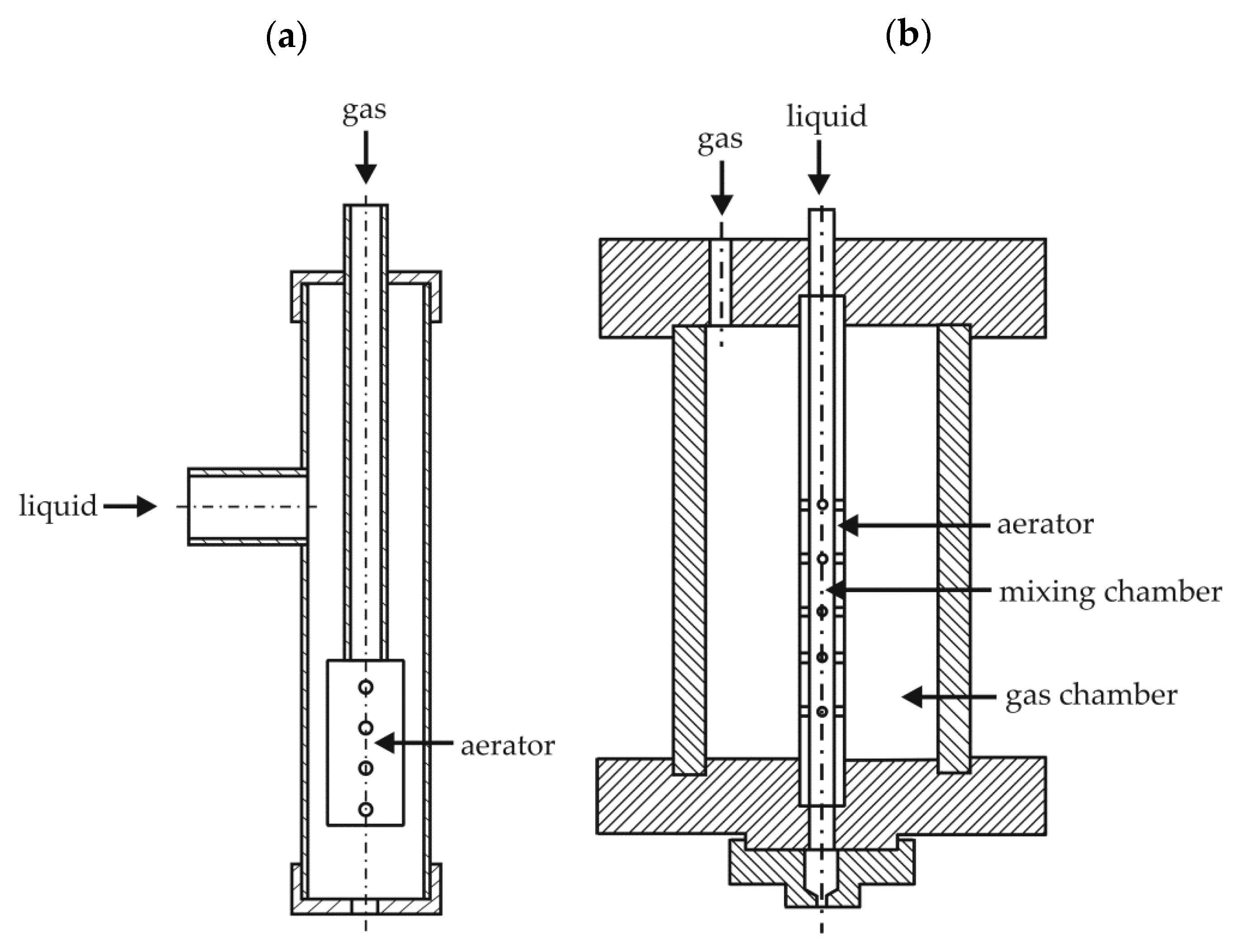
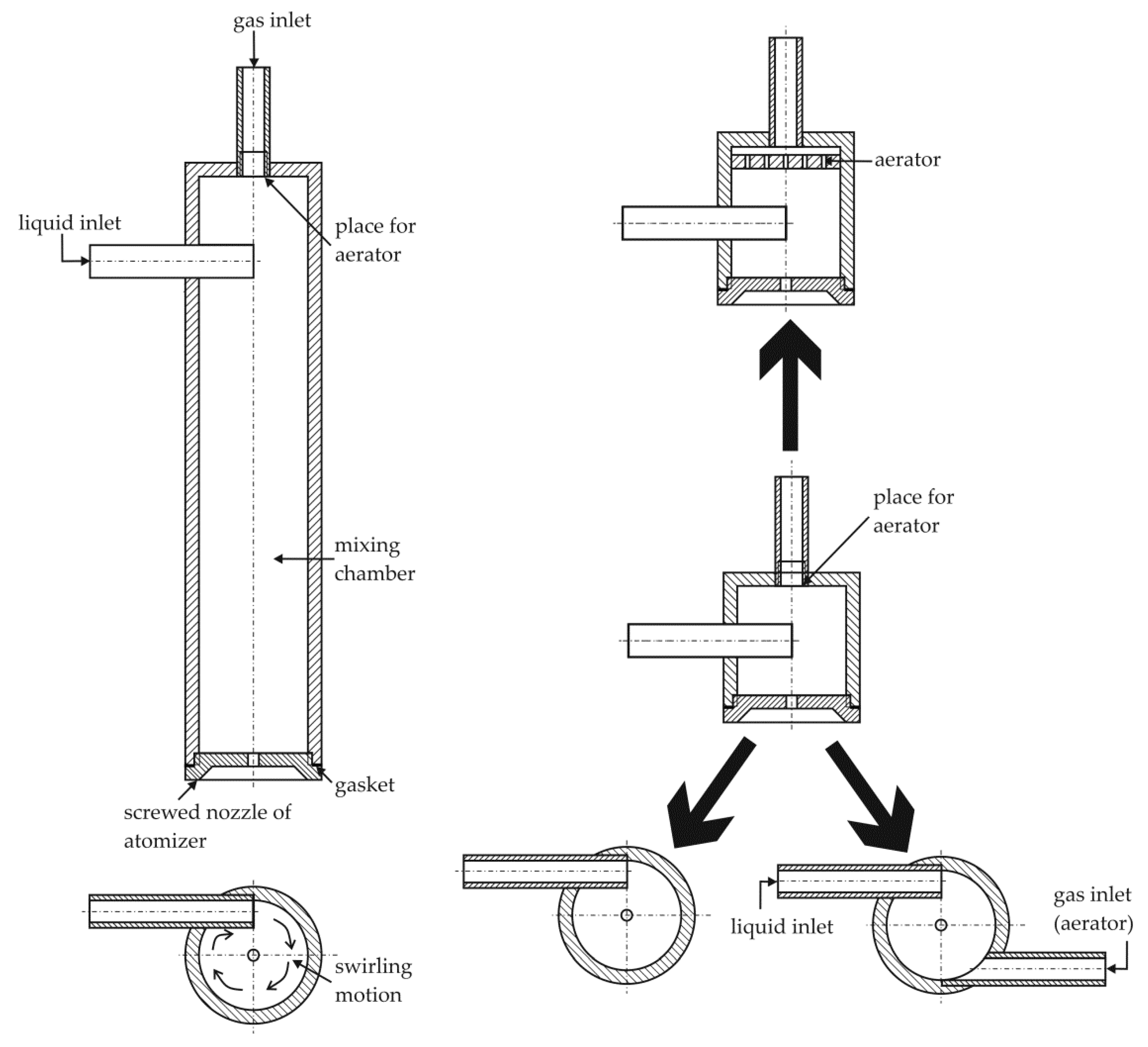
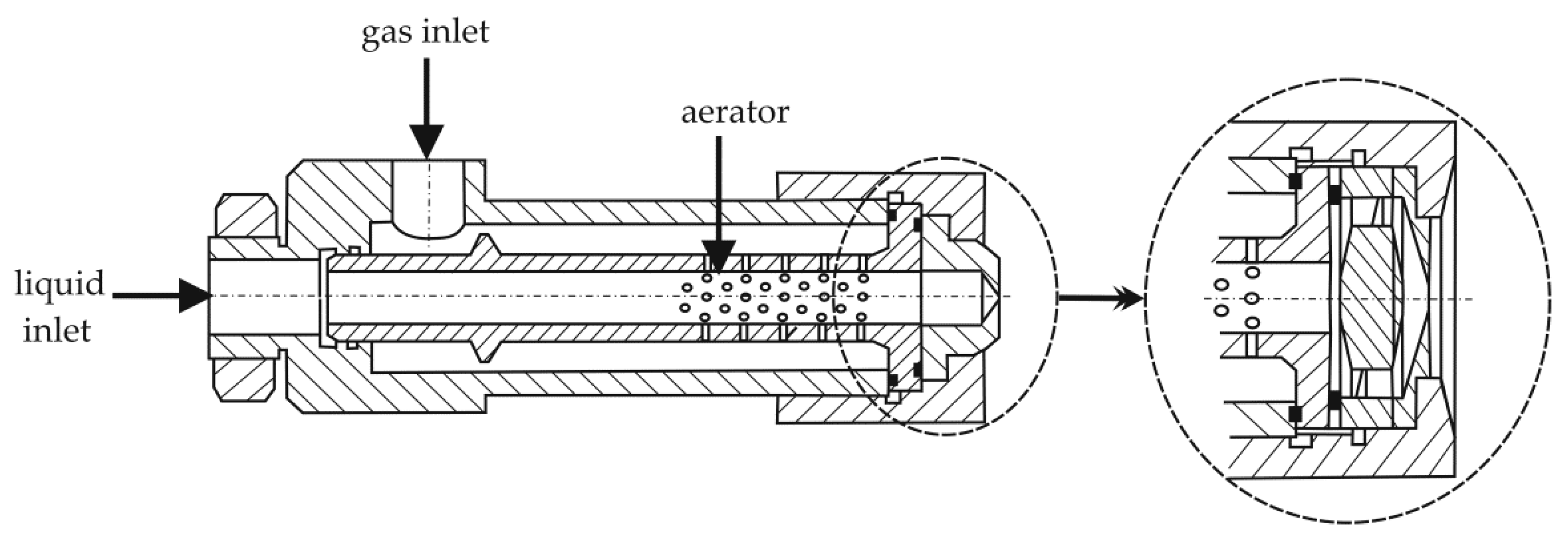
In the literature on the subject, the issue of effervescent atomizers comes in two design variants: inside-out and outside-in. Both types differ in the way gas is dosed to the system [8,42,43]. An example of the construction of both atomizers is shown in Figure 2 [20,44]. In inside-out atomizers, the gas is introduced in the form of bubbles into the liquid volume through openings in the middle of the mixing chamber [6,8]. On the other hand, in outside-in devices, gas is supplied to the mixing chamber from the surrounding annular space using small holes in the pipe (a perforated pipe is used for this purpose) [6,7,8,17,18,43]. The effervescent-swirl atomizers can be subdivided in an analogous manner, taking into account the fact that the swirling motion can be induced for the gas phase, the liquid phase, or both at the same time. Figure 3 shows the modified designs of the tested atomizers using the phenomenon of swirl motion [1,7]. The papers [8,20,45] describe atomizers with typical dimensions and atomizers with minimized dimensions (about 5 times shorter).
It is worth emphasizing that an effervescent atomizer is subject to constant modifications in order to improve the atomization process. Hammad et al. [46] showed the new design of the injector that connects the flow characteristics inside a newly designed outside-in-liquid (OIL) atomizer. This study used technique of the flow visualization and digital image processing. The experimental data proves that the new construction of OIL atomizer (whose internal geometry has been properly optimized) can overcome the spray unsteadiness problem in relation to an effervescent atomizer.
In the work of Kourmatzis et al. [47] is described a hybrid atomizer that uses an effervescent and airblast atomization mechanism. In the effervescent atomizer was added a coaxial shear flow to a central two-phase bubbly flow. This method is a simple extension of effervescent atomization. In the article are used LDA/PDA measurements, high speed microscopic imaging of the atomization zone, and advanced image processing techniques in order to measure and analyze character of produced spray. The research carried out showed that the morphology of a spray obtained by the used hybrid atomizer is different to that of a conventional effervescent atomizer showing a superposition of sinusoidal instabilities onto a bubbly two phase core.
Another paper [48] conducted an experimental study of the atomization process at multi-hole effervescent atomizers. This study used phase Doppler anemometry in order to define the spray quality. The experimental results showed that the SMD profiles of these atomizers were inversely bell-shaped, where the minimum was to the nozzle axis. It is worth noting that the radial distance had an effect on droplet diameter, where for larger radial distance we can observe the occurrence of large droplets and the distribution character changes from uni- to bi-modal. Jedelský and Jícha [48] proved that the internal geometry (including inserts, mixing chamber size, and aeration arrangement) has a significant effect on the internal two-phase flow; however, the effect on the droplet diameter is not significant. Furthermore, the experimental data shows that the spray characteristics depends on the internal geometry of the multi-hole effervescent atomizer.
In paper [49], it described the new twin-fluid nozzle. The obtained results showed the droplet characteristics and size distribution depend significantly on the coupling between the gas, liquid, and structure of the twin-fluid nozzle. The efficiency of the spraying process was determined using the method of a phase Doppler particle analyzer. The results proved that the spray atomization characteristics and droplet size distribution depend on the performance of primary and secondary atomization. Accordingly, an important role in the atomization process is played by the parameter, such as atomizing core structure and the gas to liquid mass flow rate ratio. It is worth emphasizing that better atomization efficiency was achieved for the new twin-fluid nozzle than the standard twin-fluid nozzle. The use of an atomizer with a new design of twin-fluid nozzle leads to the decrease in the droplet diameter, and also the increase in the droplet number concentration, axial velocity, and the spray cone angle.
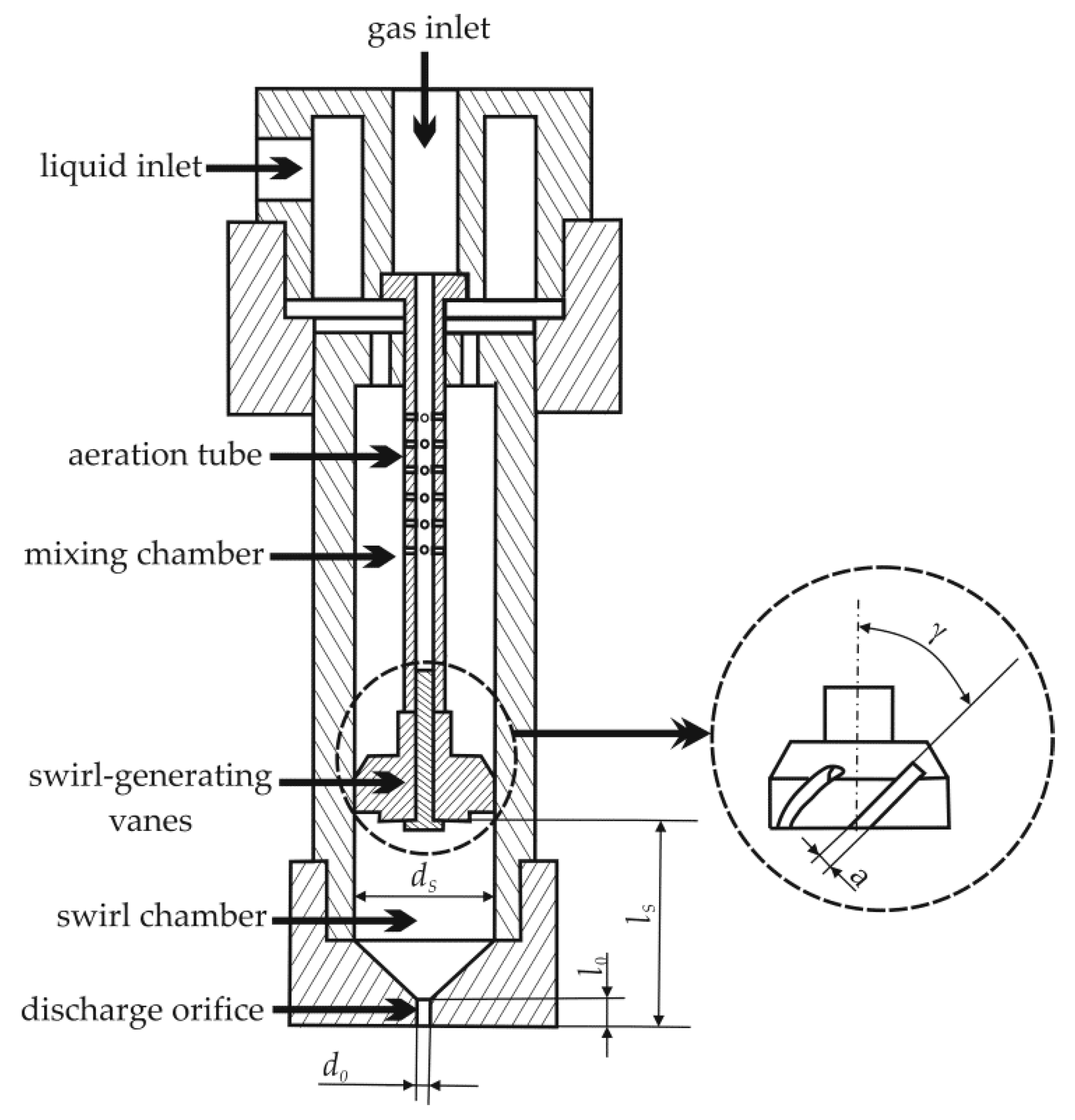
The papers [50,51,52] described an innovative design of an effervescent-swirl atomizer equipped with various types of swirl inserts (Figure 3). Three insert channels with different inclination angles were tested (Figure 4), for which the said angle was 30, 45, and 60 °C, respectively. The authors of the above works also analyzed the dependence of the spray angle on the diameter of the outlet opening of the atomizer, the value of which ranged from 1.5 to 2.5 mm.
The analysis of the obtained results proved that inside-out type atomizers perform better at low values of liquid flow rate, while outside-in type atomizers perform better at higher values of liquid flow rate [53,54,55,56,57,58,59]. The advantages of both gas-powered atomizers have not been thoroughly analyzed and clearly defined so far [8]. A standard effervescent atomizer has a diameter of about 50 mm and a length of about 100 mm. In turn, the diameter of the mixing chamber ranges from about 5 to 25 mm, and the diameters of the outlet openings range from 0.1 to 6 mm [8].
It is worth emphasizing that despite the fact that effervescent and effervescent-swirl atomizers are very popular, it has not been possible to develop a detailed calculation method yet. This is explained by the fact that so far it has not been possible to define in an unambiguous manner how the gas and liquid phases interact during the flow. Based on the experimental studies conducted so far, which were carried out in a wide range of parameter variability, it is possible to propose correlation equations. These equations concern the relationship between: the design of the atomizer, the properties of the sprayed liquid, the flow rate of the media and the diameter of the formed aerosol droplets. These dependencies are especially useful in the design aspect of atomizers. Examples of the equations are described in a later part of the article.
A very important issue in the atomization process is its optimization in order to reduce the costs of liquids and chemicals, unplanned production stoppages, energy consumption, and the negative impact on the environment, as well as to extend the operating time of the atomizer and improve the quality of spraying [17,20,60,61]. In the process of designing an effervescent-swirl atomizer that generates droplets of the desired size, the diameter of the atomizer outlet opening, which significantly affects the quality of atomization should be taken into account. The research carried out and published in the work [45] showed that as the diameter of the outlet opening increases, the quality of atomization deteriorates clearly. However, it should be remembered that the large diameter of the outlet opening is its main advantage, as it allows to minimize the problem of its clogging during spraying contaminated liquids or suspensions [62]. Therefore, it is assumed that the selection of the minimum diameter of the outlet opening should be based on the maximum value of the mass flow rate, taking into account also the possibility of clogging the opening or its possible erosion [17,56].
Another important aspect in the atomization process is the shape and diameter of the mixing chamber [8,48,62,63,64]. Based on the research described in [65,66,67], one main conclusion can be reached that if the mixing chamber has a small diameter, it does not affect the size of the generated droplets. On the other hand, when the mixing chamber diameter is greater than 5 mm, a significant effect on the mean diameter of the droplets is observed [65,66,67].
Other studies describe the dependence of the atomization process on the type of aerator used. The research described in the work [68] proves that the design of the aerator itself has practically no effect on the size of the formed droplets. However, the authors emphasize that the use of an atomizer with a multi-hole aerator makes it possible to obtain an aerosol of a slightly more monodisperse character than in the case of using an atomizer with a single-hole aerator. In both cases, the atomization process was carried out for the same total cross-sectional area of the gas inlet openings. In addition, the study also proved that an atomizer with a single-hole aerator is more effective when applying low injection pressure. A clear effect on the size of the generated aerosol droplets was noted for the ratio of the area of the outlet opening to the total area of the aerator’s openings [42,45]. This ratio describes the gas velocity coefficient, the value of which depends on the diameter and number of holes in the aerator. It is assumed that its optimal value is expressed by the formula [67]:
( A 0 A A , h ) o p t = 6.3 G L R
Accordingly, it can be concluded that the atomization process using effervescent atomizers can be carried out with gas supply aerators with a large opening diameter.

2.2. Liquid Flow Structures

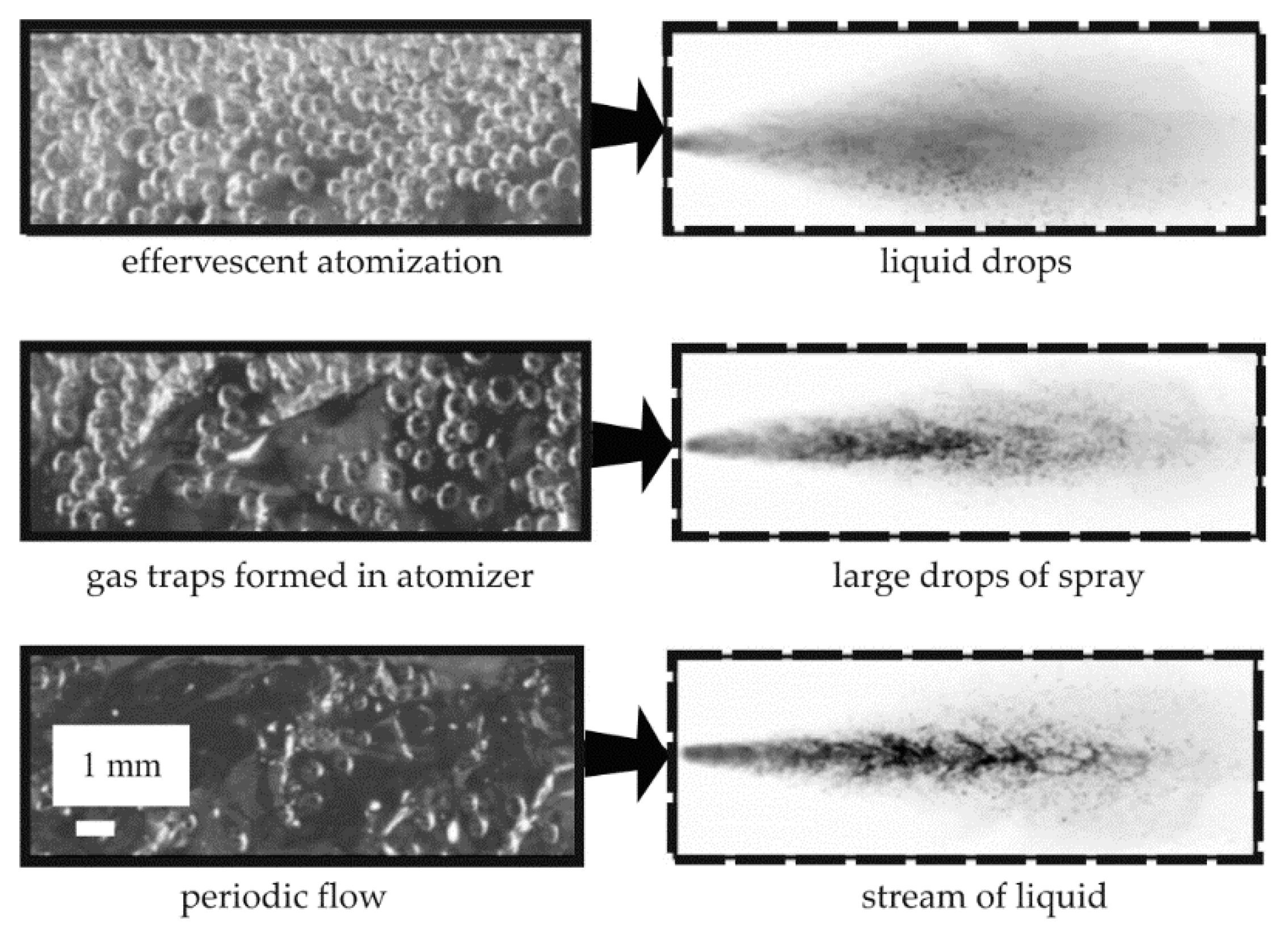
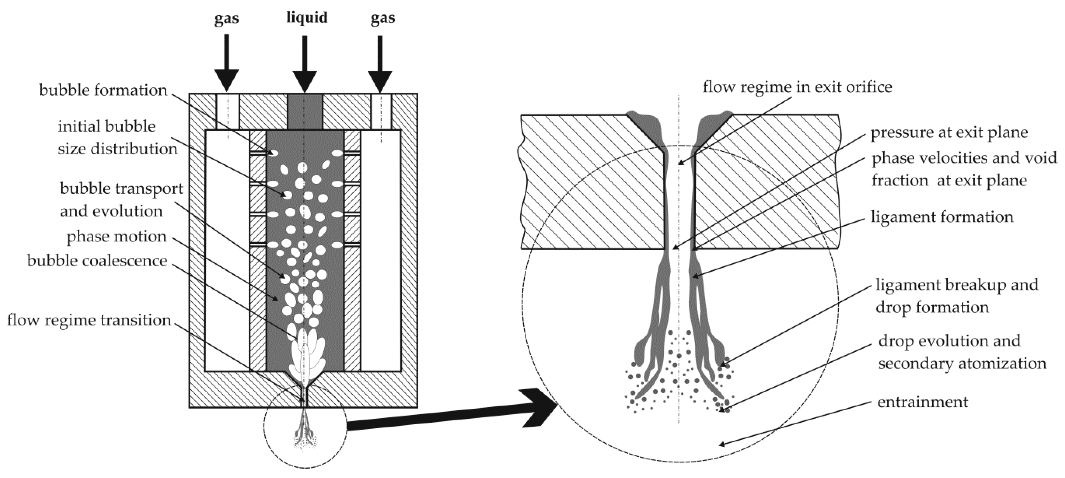
A review of the literature shows that in an effervescent atomization process, a flow structure similar to the one occurring in the case of swirl atomizing may appear at the outlet. This situation also applies to the formation of an air core in the spray axis [7,8]. The introduction of swirl motion to effervescent atomizers intensifies the presence of the air core. This process includes complex two-phase phenomena that are difficult to describe and model [8]. The flow occurring in effervescent atomizers takes a more complicated form than the other one-phase and two-phase atomizers. The atomizing mechanism is based on the mixing of both phases (gas and sprayed liquid) inside the device. The development of the two-phase mixture occurs as it flows through the atomizer until it is sprayed at the outlet opening. An example of the atomization process in this type of devices is shown in Figure 5 [7,8,9,69,70,71,72,73,74].
In effervescent atomizers, both gas and liquid are supplied by means of inlet stubs. The gas is dosed into the system at a pressure slightly higher than that of the liquid using the perforated aerator pipe for the liquid-phase, so that the gas supplied takes on a form of bubbles. The two-phase mixture thus formed flows into the nozzle outlet of the atomizer. The method of spraying, the development, and structure of the mixture are mainly dependent on the geometry of the gas injection, the outlet opening of the atomizer, the shape and size of the mixing chamber, the injection pressure, the gas/liquid flow ratio, and the physical properties of the liquid. In the mixing chamber, it is possible to observe the phenomenon of bubble formation, their transport, and the changes taking place in the form of joining or breaking, as well as the movement of the gas and liquid phases. In turn, in the vicinity of the outlet opening, the mixture is compressed. At the outlet of the atomizer, a rapid expansion of the gas phase takes place, which leads to the breakup of the liquid stream, the formation of films and jets of liquid, and the jet breakup (primary and secondary breakup) [8,29,75,76]. The two-phase mixture that exits the atomizer outlet can take various forms (it can be a foam, a stream, or a ring), where the swirling of the liquid causes the formation of an annular structure. The authors of [10,11,12] analyzed the mechanism of liquid jet breakdown and noticed that larger drops are formed from larger jets. Bar-Kohany and Levy [76] described experiments with flash-boiling atomization, which proved that the nature of bubble growth should be addressed and analyzed, because bubbles lead to more efficient atomization process.
Different flow structures are distinguished in the outlet opening: effervescent, ring-dispersion, annular, cork, and foam, as shown in Figure 6 [75,76,77,78,79,80,81,82]. The effervescent structure is characterized by a small number of tiny bubbles that are evenly distributed throughout the volume. However, in the cork structure there is an object called a cork. In the cork structure, the relative interphase surface decreases with respect to the bubble structure. On the other hand, in the foam structure, the occurrence of a large irregular object can be observed. The number of objects in the tested volume decreases, while the size of the relative interfacial surface remains practically unchanged in relation to the cork structure. The ring structure, also known as a lamellar, ring-bubble, and ring-dispersion structure are characterized by a fully developed regular air core. Small droplets of liquid may be present inside the air core. These structures are characterized by the largest relative volume fraction of the gas phase [78,80,83].
Kourmatzis et al. [47] analyzed the hybrid atomization (effervescent and air-blast atomization) and showed that the air-blast mode has a significant impact on the sizes of generated ligament at the exit orifice for GLR equal to <2.7%. Experimental data shows that the coaxial flow makes it possible to entrainment of air in the central core, thereby influencing the degree of atomization and dispersion in relation to the pure effervescent mode.
The flow regime inside in the new atomizer (outside-in-liquid) is controlled using the perforated chamber geometry and also the exit orifice diameter [46]. Studies showed that the operating conditions do not affect the stability of the annular flow, which generated while a perforated chamber with many small injection holes and a small exit orifice were used. However, in the case where the atomization is carried out with a perforated chamber with a few large injection holes and/or a larger exit orifice, we can observe the existence of four flow regimes inside the mixing chamber (such as inhomogeneous bubbly, slug, wavy-annular, and stable-annular flows). It was also observed in [46] that the transition between defined regimes are dependent on the operating conditions. The obtained results shows the relationship between the gas-to-liquid ratio (GLR), the relative mixing pressure (RΔp) and transition between flow regimes. It was observed that the increase in GLR provides faster to the transition to the annular flow; however the increase in RΔp causes the delay of transition. Based on the obtained results for the design of OIL atomizer, a new correlation equation is created:
G L R 1.628 R d o 3.4 R Δ p 0.8 ( ρ G ρ L d G 2 d L 2 R i h sin θ ) 0.314 = 11 300
This correlation is suggested for the transition criterion between the favorable annular flow and the unfavorable intermittent flow, where Rdo is relative exit orifice diameter, Rih is relative area of a single injection hole, θ is angle, dG diameter of gas phase, and dL diameter of liquid phase.
In the work [85], the relationship between the gas flow rate and the angle of inclination of the insert channels and the air core formed during spraying was demonstrated. The conducted tests prove that the diameter of the air core increases with the increase of the gas flow rate and the angle of the swirler channels inclination. Selected results of the research described in the work [85] are presented graphically in Figure 7. The clear influence of the used insert on the diameter of the air core is visible, first of all, at higher values of gas flow rates. Additionally, it has been shown that an increase in the diameter of the atomizer outlet opening contributes to an increase in the diameter of the air core.
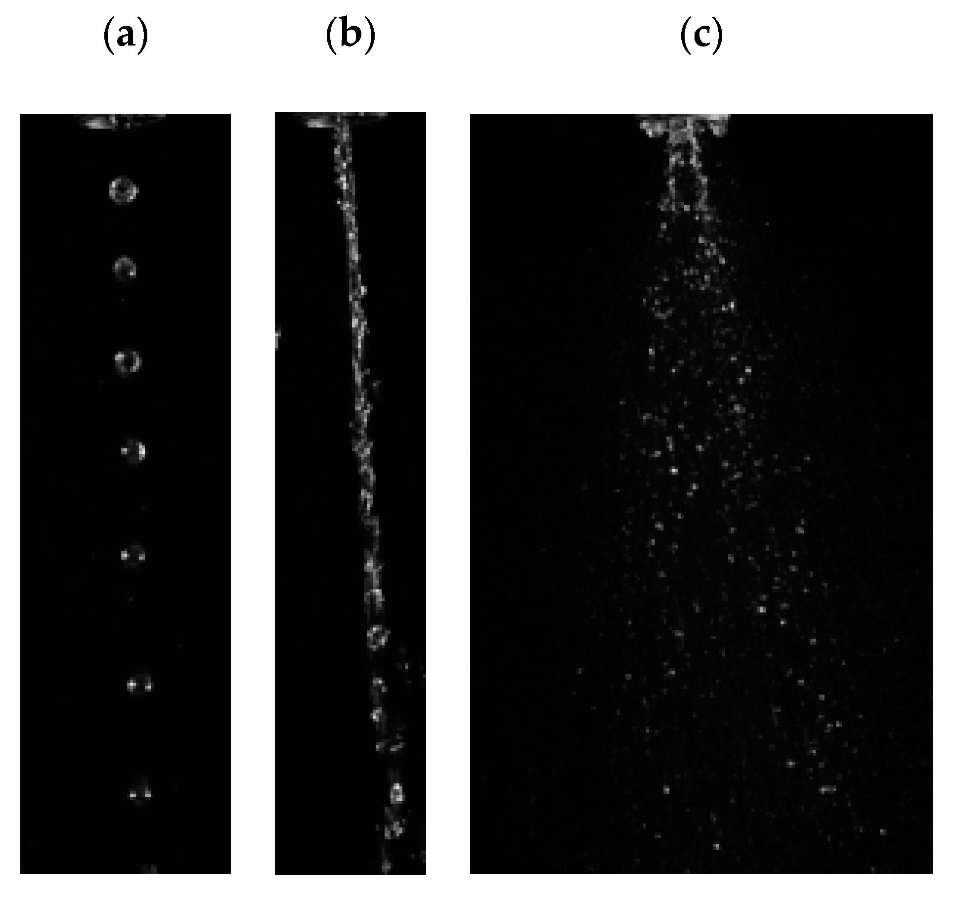
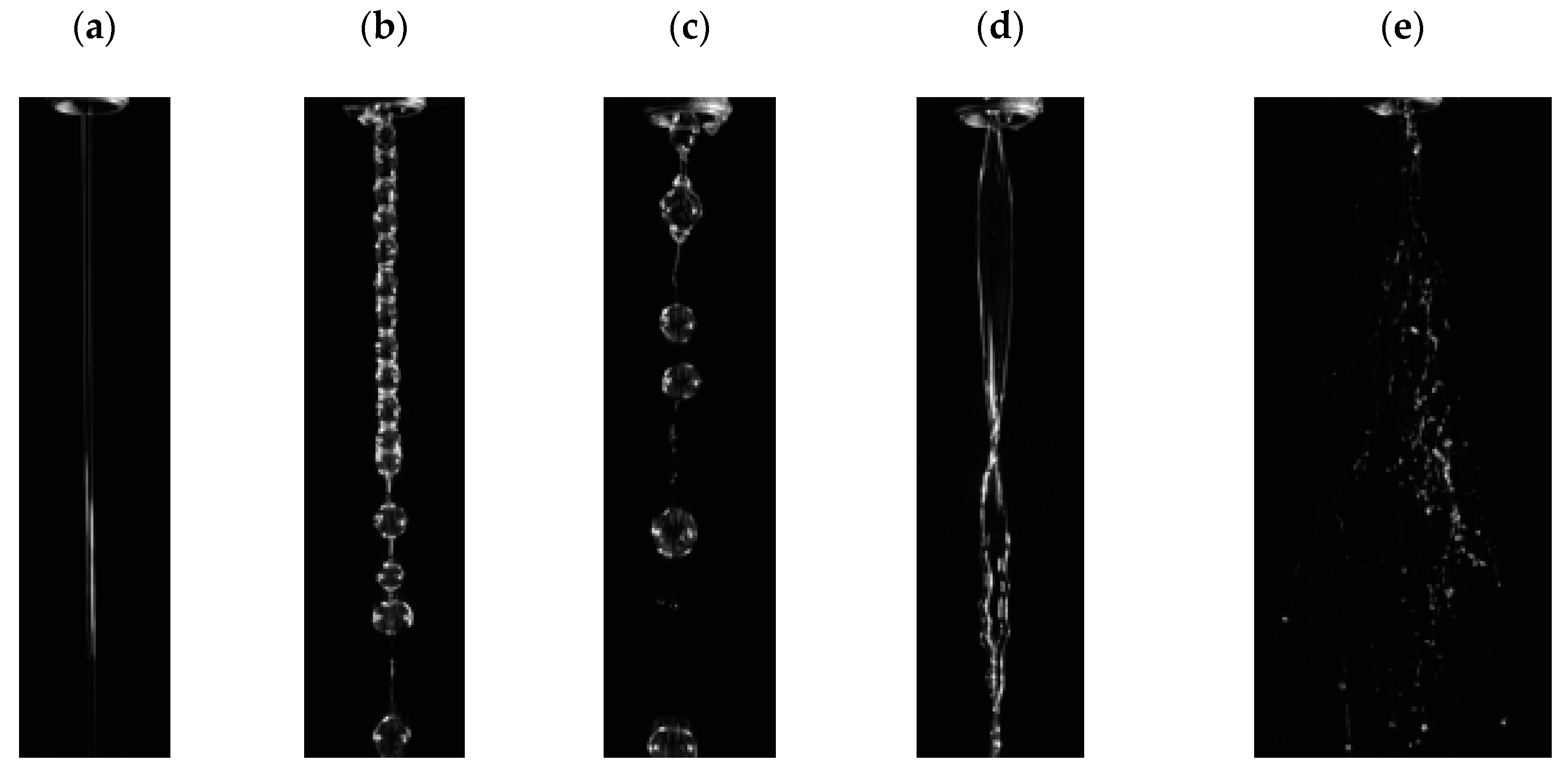
The authors of the work [45] conducted an in-depth analysis of the liquid flow structure at the outlet opening of the atomizer. The atomization process was carried out for a single and two-phase system. Selected photographic images of the sprayed liquid for the air-water system are shown in Figure 8, and for the system of air-water glycerin solution with polymer addition in Figure 9.
During the flow of 59% aqueous glycerin solution with the addition of 0.5% rocrysol WF1 in the effervescent-swirl atomizer, turbulences were observed on the surface of the stream due to swirling of the liquid stream (Figure 9d) [7]. The presented photos show the characteristic beads-on-a-string structure (BOAS) of a stream, i.e., thin threads of the sprayed liquid interconnecting the droplets (droplet-fibrous form of a stream) (Figure 9b). When spraying liquids with significant viscosities, the spray angle is reduced until a stream with large fibers and droplets is formed (Figure 9e). However, the appearance of turbulent flow, as a result of the increase in Reynold’s number, contributes to the destruction of the liquid structure and the reduction of the liquid viscosity, which results from the properties characteristic of non-Newtonian liquid properties [7].
On the basis of the conducted research, it has been shown that as a result of the atomization process, it is possible to observe, inter alia, the breakup of the jet into droplets, the phase of a bent pencil, and proper spraying [5,7,45]. Moreover, the appearance of a jet with droplets, a jet of sprayed liquid with gas bubbles, a jet of individual bubbles and bubbles connected with liquid fibers was also observed. It is worth emphasizing that the obtained images are characteristic of liquids of significant viscosity (especially longitudinal viscosity). These conclusions confirm previous literature reports [45].
Most likely, the addition of polymer results in an increase in the longitudinal viscosity, which leads to the formation of a coarse-fiber structure and delay of the stream breakup [86,87]. This phenomenon is beneficial in many applications [5,88]. As a result of spraying aqueous polymer solutions, a droplet-fibrous structure is formed. It is worth noting that during the atomization process, the occurrence of the so-called secondary destabilization of the fibers connecting the droplets, which in turn causes the appearance of very small droplets, was observed. Despite the fact that the use of a polymer additive causes an increase in the thickness of the fibers (Figure 9d), as well as the suppression of disturbances causing delayed breakup of the streams, the liquid stream becomes thinner with increasing distance from the nozzle outlet, which in turn leads to secondary growth oscillations on the surface of the liquid and the breakup of the threads into drops of very small diameters [7].

2.3. Discharge Coefficient

In order to fully assess the design of the atomizer, it is also necessary to analyze the pressure drops occurring at its tip and in the body (i.e., drops occurring on the stub-tubes, in the aerator and in the mixing chamber). The studies carried out so far prove that the greatest pressure drops occur at the outlet end, while the smallest pressure drops occur in the pipe, which constitutes the mixing chamber. With the increase of pressure drops in the atomizer, the value of the discharge coefficient determined for the whole atomizer is observed to decrease. In a situation when the value of the mass gas stream is close to or equal to zero, it is assumed that the calculation of the spraying parameters for effervescent-swirl atomizers (including the flow coefficient) is simplified to the calculations used in the case of single-phase atomizers characterized by the same geometry [5,6,89,90,91].
The relationship between the ratio of length to the diameter of the outlet opening l0/d0 the discharge coefficient is very complex. In the range of values l0/d0 < 2, the liquid stream is contracted. On the other hand, when l0/d0  2, the stream expands within the opening, which means that its outflow is the same as in the case of the so-called adapters/attachments. In the narrowest cross-section of the liquid stream there is a negative pressure leading to an increase in the liquid flow. It happens that when appropriate conditions appear, the flow velocity increases the phenomenon of liquid stream detachment from the opening occurring. Due to the above, there is a possibility of the stream narrowing and a marked decrease in the liquid flow [5,14]. In the works [6,7,92], it was proved that the value of the discharge coefficient depends to a large extent on the ratio l0/d0, but also on the shape of the inlet section of the atomizer’s tip. The values of the liquid discharge coefficient are quite varied and depend on the type of the discharged orifice used, otherwise the so-called diffuser [14,93]. Moreover, experimental studies have shown that the size of the l0/d0 ratio plays a key role in a situation where the Reynolds number values are small.
The authors of the work [7] estimated the correlation equation that allows to determine the value of the flow coefficient for single-phase flow, which takes the form:
C D = { [ R e c 0.88 64 ( l 0 d 0 ) 1.15 ( d 0 D s ) 1.15 ( η c η w a t e r ) 1.15 + 53.88 ] 3 + [ 1 ( d 0 D s ) C D , t u r 2 ] 3 } 0.165  
It is worth noting that this equation is valid for a Reynolds number in the range from 20 to 40,000, and CD, tur is the value of the fluid discharge coefficient during a turbulent flow.
It should be emphasized that in the case of effervescent-swirl atomizers, it is more important to determine the value of the flow coefficient for a two-phase flow. It is also worth noting that in the case of effervescent-swirl atomizers, a smaller influence of the tips on the value of the liquid discharge coefficient during a turbulent flow was noted than in the case of standard effervescent atomizers. Due to the above, it is possible to obtain some savings by using tips with lower accuracy and lower quality in the production and use, avoiding the risk of deteriorating the quality of the spray obtained [7].
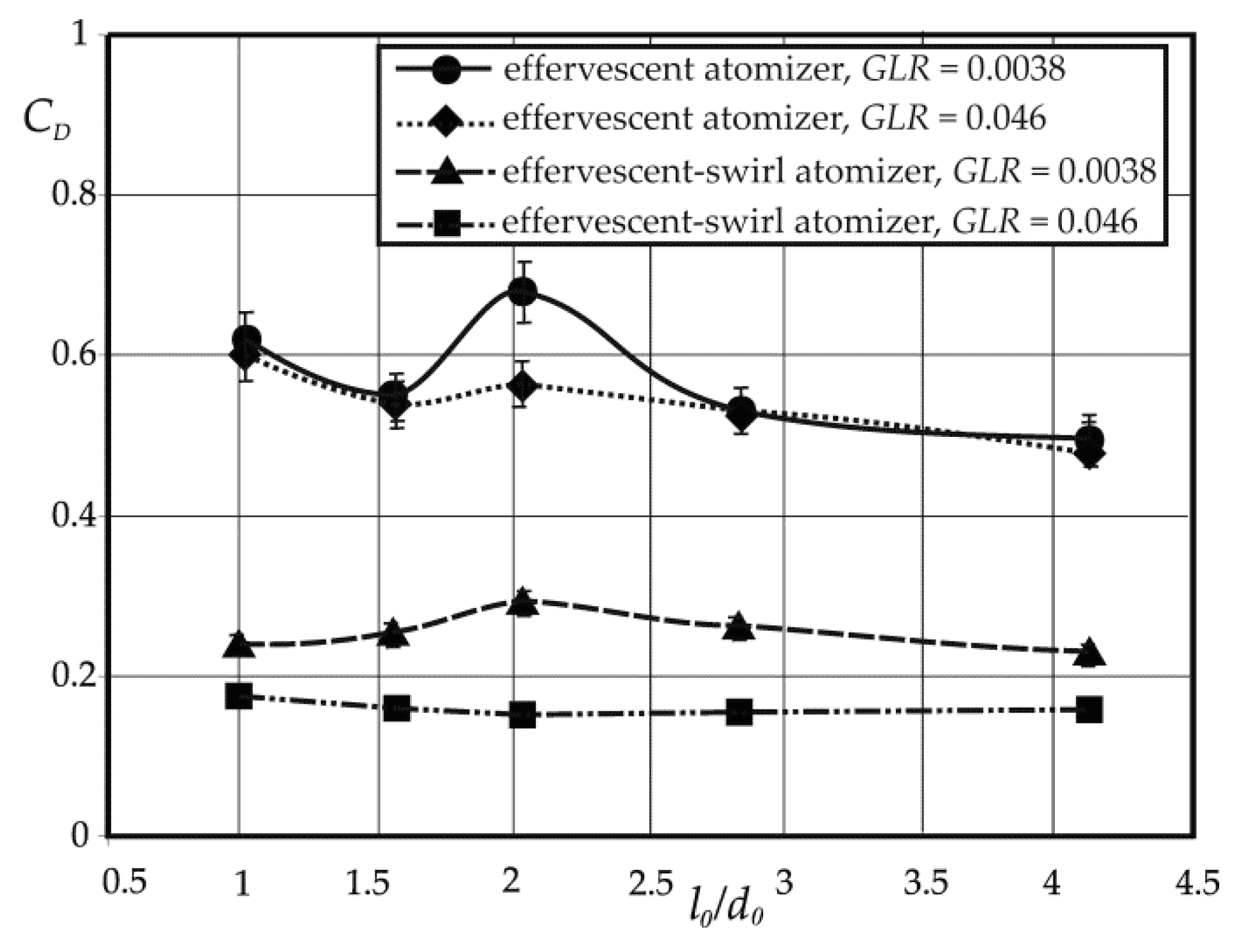
Figure 10 shows the effect of the l0/d0 ratio on CD during a two-phase flow for the two selected GLR values of 0.0038 and 0.046. The results obtained for the process carried out with the use of an effervescent-swirl atomizer showed that the value of the discharge coefficient was increased until reaching the maximum value equal to 2.04. In turn, a further increase in the l0/d0 value contributes to a decrease in the CD value. This phenomenon is explained by the occurrence of an increase in friction forces, which occurs as a result of an increase in the value of l0 (extension of the outlet opening length). Additionally, the conducted research proves that the geometry of the outlet opening does not affect the discharge coefficient or affects it only slightly in the situation when the GLR values are large [7]. Moreover, it was noticed that the values of CD, determined for all tested atomizers, decrease with the increase in the GLR value. The authors of the work [7] developed a correlation equation that allows to estimate the liquid discharge coefficient in a two-phase flow for the outlet opening (atomizer tip) with the following form:
C D = 0.0822 ( η c η w a t e r ) B ( σ c σ w a t e r ) 0.02 C D , t u r G L R 0.43  
It is worth emphasizing that in the analyzed atomization process, the influence of viscosity is not obvious and it is visible only when GLR values are small [14,94,95]. Most likely, this is due to the fact that while the GLR takes low values, the nature of the two-phase flow is similar to that of a single-phase liquid flow (where the gas addition is minimal), and therefore the effect of viscosity on the flow can be observed. On the other hand, when the GLR values are higher, the viscosity of the gas phase plays a significant role. Similar conclusions can be drawn after analyzing the results of research on classic swirl atomizers [14]. These studies prove the occurrence of a certain liquid viscosity value in the atomization process, which is assigned the maximum value of the discharge coefficient [14]. The maximum value of the mass stream of liquid occurs when the liquid turbulence disappears (with a certain liquid viscosity), which leads to the liquidation of the air core and the outflow of the liquid itself out of the atomizer outlet opening. On the other hand, a continuous increase in the viscosity of the liquid leads to a decrease in the stream mass caused by an increase in frictional resistance [14].
A review of the literature revealed several papers devoted to the analysis of flow resistances [7]. The data contained in the studies make it possible to estimate the value of the discharge coefficient on the basis of semi-empirical [96] or empirical [44,97] correlation equations. By contrast, [98] describes the combination of two analytical models in order to determine the value of the discharge coefficient. For this purpose, the homogeneous flow model (HMF) and the separated flow model (SFM) were used [98].
In the work [96], the authors, on the basis of the conducted research, proposed a model equation for the discharge coefficient of atomizers, taking into account the external gas supply:
C D = c ( 1 V ˙ g V ˙ g + V ˙ c ) 0.3 ( 1 + 1 G L R ) 0.15
In this equation, the value of CD depends on the properties of the liquid (viscosity and density) and takes various values, which are listed in Table 1 [96]. This equation is limited to the value GLR < 0.12.
According to the authors of the work [99], the liquid flowing through the outlet opening does not fill it in the entire cross-section, and the formed air core is surrounded by a liquid ring. This situation is analogous to the phenomenon that occurs when spraying with swirl atomizers. Based on the conducted research and analysis of the obtained results, a correlation equation was proposed in the form (valid for GLR ranging from 0.02 to 0.46):
C D = 0.0088 ( G L R d 0 D s ) 0.75 ± 14 %
In turn, Jedelsky and Jicha developed another form of the model equation to determine the value of the discharge coefficient [98]. This equation is based on two flow models: homogeneous flow and stratified two-phase flow. This relationship takes the following form:
C D = 0.62 ( η c η w a t e r ) 0.04 ( σ c σ w a t e r ) 0.02 ( l 0 d 0 sin ( 2 φ ) 0.5 ) 0.11 M ˙ c A 0 ( 2 ρ c Δ P ) 0.5 1 ( 1 + G L R )
where φ is the inclination angle of the mixing chamber wall. This equation is consistent with the data described in the work [4]. Equation (7) allows to determine the CD value with an accuracy of ± 10%, thanks to which it is currently the most universal and takes into account the largest number of variables.
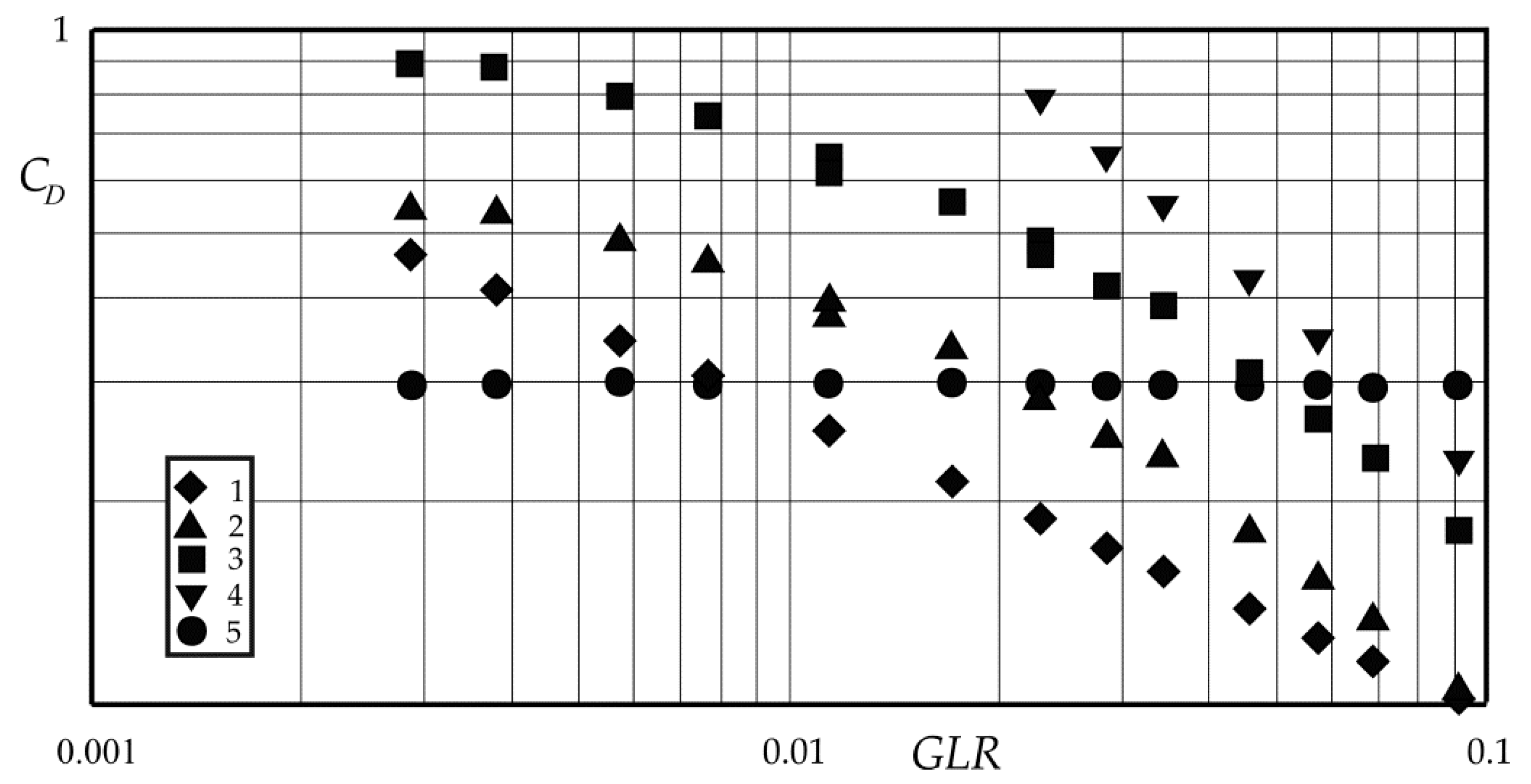
Figure 11 summarizes the dependencies of CD on GLR, drawn on the basis of a literature review [1,7,44,96,98]. Due to the fact that the atomization process was carried out with the use of atomizers of a different design, no direct comparative analysis can be performed. The analysis of the data presented in the graph shows one common tendency, where the value of the discharge coefficient decreases with the increase of the GLR value [100]. An exception to this rule is the research results presented by Ramamurthi et al. [97], where a practically constant value of CD can be observed.
The dependence of the discharge coefficient on the liquid viscosity is theoretically included in the equations containing the Reynolds number and in Equation (6). On the other hand, the analysis of literature data related to the effervescent and effervescent-swirl atomization process [4,75] proves that the influence of liquid viscosity (for Newtonian and non-Newtonian liquids) on CD can, as a rule, be neglected. Studies have shown that the influence of liquid viscosity is greater when GLR takes lower values. At the same time, at higher GLR values (>0.07), we do not observe the viscosity influence. The obtained results are consistent with the studies published in the works [94,101,102].

2.4. Spray Angle

Chen and Lefebvre [53] conducted research on the spray angle of liquids of different viscosity and surface tension. The obtained results prove that the size of the estimated spray angle is much greater than the values obtained for pressure atomizers of similar design. In turn, in the work [36] it was shown that the value of the spray angle rapidly decreases in the vicinity of the outlet opening, and then it assumes an approximately constant value. The spray angle increases as the gas pressure increases and the viscosity and surface tension of the liquid decrease. The work [53] says that the spray angle takes values lower than 23°. This is confirmed by the studies described in the work [35,36,58,60,103], which show that the values of the liquid spray angle with the use of effervescent atomizers with a single-hole aerator take values not greater than 22–23. The literature review reports that the spray angle values obtained for effervescent atomizers are lower values compared to other types of atomizers (except pressure ones) [5,6,53,103].
In the literature on the subject, works devoted to the analysis of the spray angle are very rarely found. However, the published works determine congruently that the spray angle size increases monotonically as a result of the injection pressure increase [35,53,72,101,104]. In the work [35], the following correlation equation for the spray angle was proposed:
α 2 = ( 15 G L R ) + ( 0.039 P i n ) + ( 0.0451 P o t 4 0.6211 P o t 3 + 2.7551 P o t 2 3.62 P o t ) + 7.0  
where the pressure values are included in the unit of megapascal.
In several studies, a dependence of the increase in the size of the spray angle with the increase in the GLR ratio was noted [35,53,105,106]. Moreover, Chen and Lefebvre [53] and Jedelsky et al. [106] observed a decrease in the spray angle value after reaching a certain maximum value, which most probably results from a gradual change in the internal flow structure (transition from bubble to annular structure). Additionally, it was noted in the work [106] that reducing the spray angle may cause an increase in the ratio of the outlet opening length to its diameter from 0.08 to 1.2.
Loebker and Empie [107,108] published their studies of the process of spraying highly viscous liquids and obtained relatively large spray angle values of about 60°, where GLR was greater than 0.003. Moreover, the analysis of the results proved that not only the viscosity of the liquid, but also its flow rate has a significant impact on the spray angle value [7,107,109,110]. The highest spray angle values published in the works [109,110] were about 80°, and in the work [111] the angle value reached even 150° (at GLR ≈ 0.07000), where Newtonian liquids were sprayed using an atomizer with an internal gas flow. The maximum angle value was reached with GLR ≈ 0.07000, after exceeding this value, a sharp decrease in the spray angle value was observed.
The research on the atomization process carried out in effervescent-swirl atomizers with the use of different gas and liquid flow velocities presented in the work [4] showed that the increase in gas flow velocity has a beneficial effect on the spray angle value (especially in a situation where the value of the mass flow rate of liquid is small). This is explained by the fact that the use of low flow velocities causes the liquid to flow as a compact jet, from which individual drops are detached. With a further increase in the value of the gas flow velocity, the stream of liquid breaks down into droplets, and thus the spray angle increases. At the moment when the stream of gas is significant, we observe the phenomenon of flowing around the stream of the sprayed liquid, so the spray angle is reduced. It should be remembered that the use of a too large stream of liquid may lead to an increase in the volume of the stream and difficulty in its spraying. Accordingly, we can observe a decrease or increase in the size of the spray angle. These observations were confirmed in the work [75], where the possibility of the maximum spray angle occurrence and its non-linear dependence on the GLR value was demonstrated. The described process can be explained by the flow transition from the bubble to the cork (or annular) range inside the atomizer, caused by the presence of low GLR values and operating pressure. Another explanation for the phenomenon is its occurrence as a result of a rapid increase in the volume of gas bubbles right at the outlet of the atomizer orifice, which may contribute to increasing the spray angle.
It should be remembered that the spray angle is also influenced by the internal geometry and dimensions of the atomizer [5,96,112], which include, e.g., the diameter of the atomizer outlet opening [45,111,113], and the diameter of the swirl chamber [5,6,114]. One cannot forget about the viscosity of the sprayed liquid either [45,111,113,115,116].
In the work [4], another correlation equation taking into account the spray angle was proposed:
α = A C D , t u r 0.9 D 0.39 d k 0.78 η c 0.31 d 0 1.02 M ˙ c 0.25 G L R 0.21
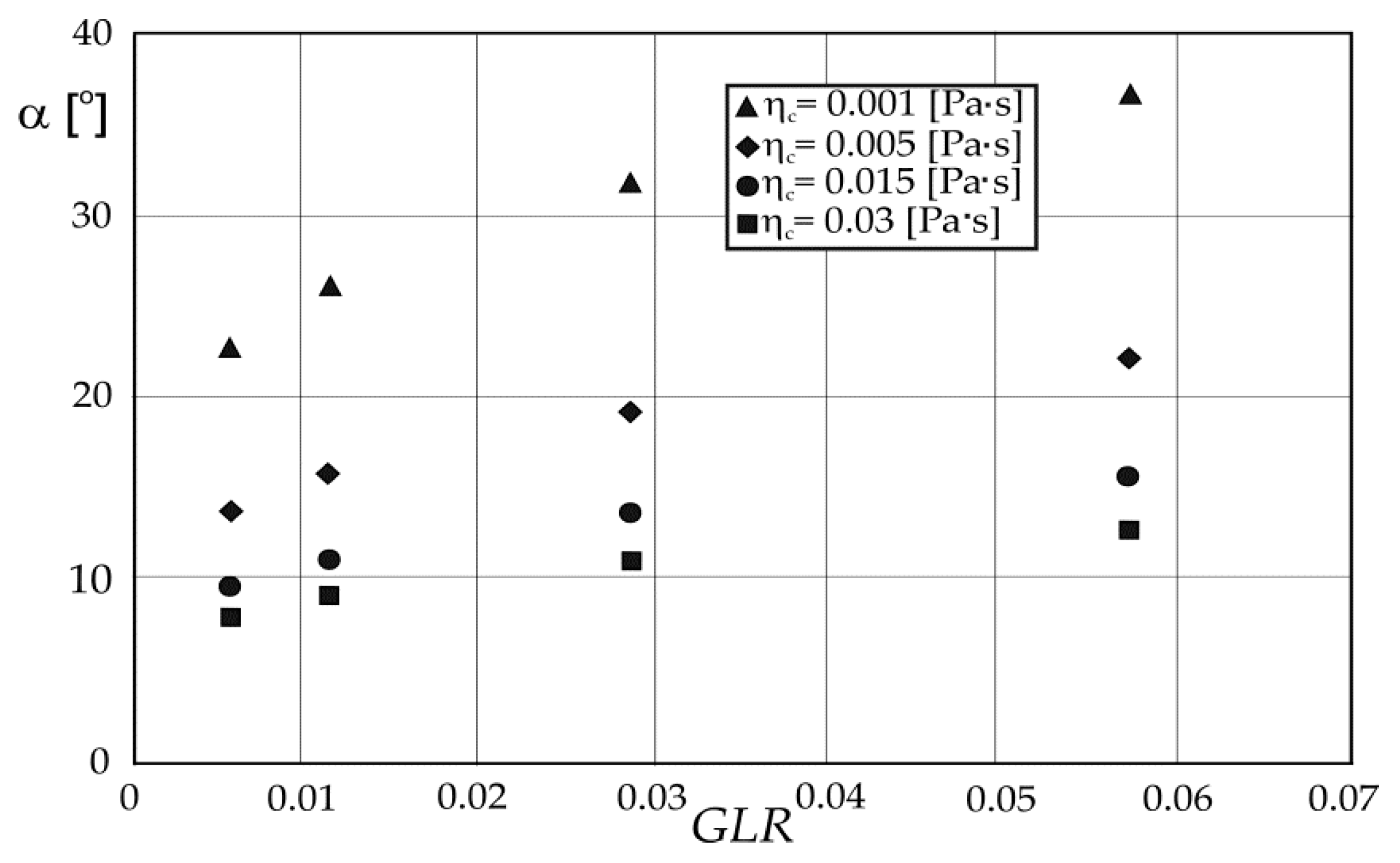
where: A is the constant for the design of the atomizer, and dk is the diameter of the liquid inlet stub-tube [5,6]. For the analyzed atomizers, the value of the constant A which is equal to 901, was determined experimentally [7]. It is worth noting that the above equation is correct for the entire examined range of the considered variables. Figure 12 shows graphically examples of the relationship between the spray angle and the viscosity of the liquid [7].
As mentioned before, the spray angle depends, apart from the process conditions, also on the design of the atomizer itself; however, all variables cannot be taken into account in the correlation equation. This is confirmed by the research conducted by Jedelski and Jichy [117]. The study showed that the α value for effervescent atomizers increases due to the increase in GLR value, and then reaches its maximum value at the GLR value of about 0.1, after which this value decreases. Moreover, it has been proven that the atomizers additionally equipped with swirl inserts have larger spray angle sizes than the atomizers with cylindrical outlet openings [117].
In summary, it can be stated that in order to obtain relatively large spray angles, the process should run within a GLR range of about 0.02 to 0.1.
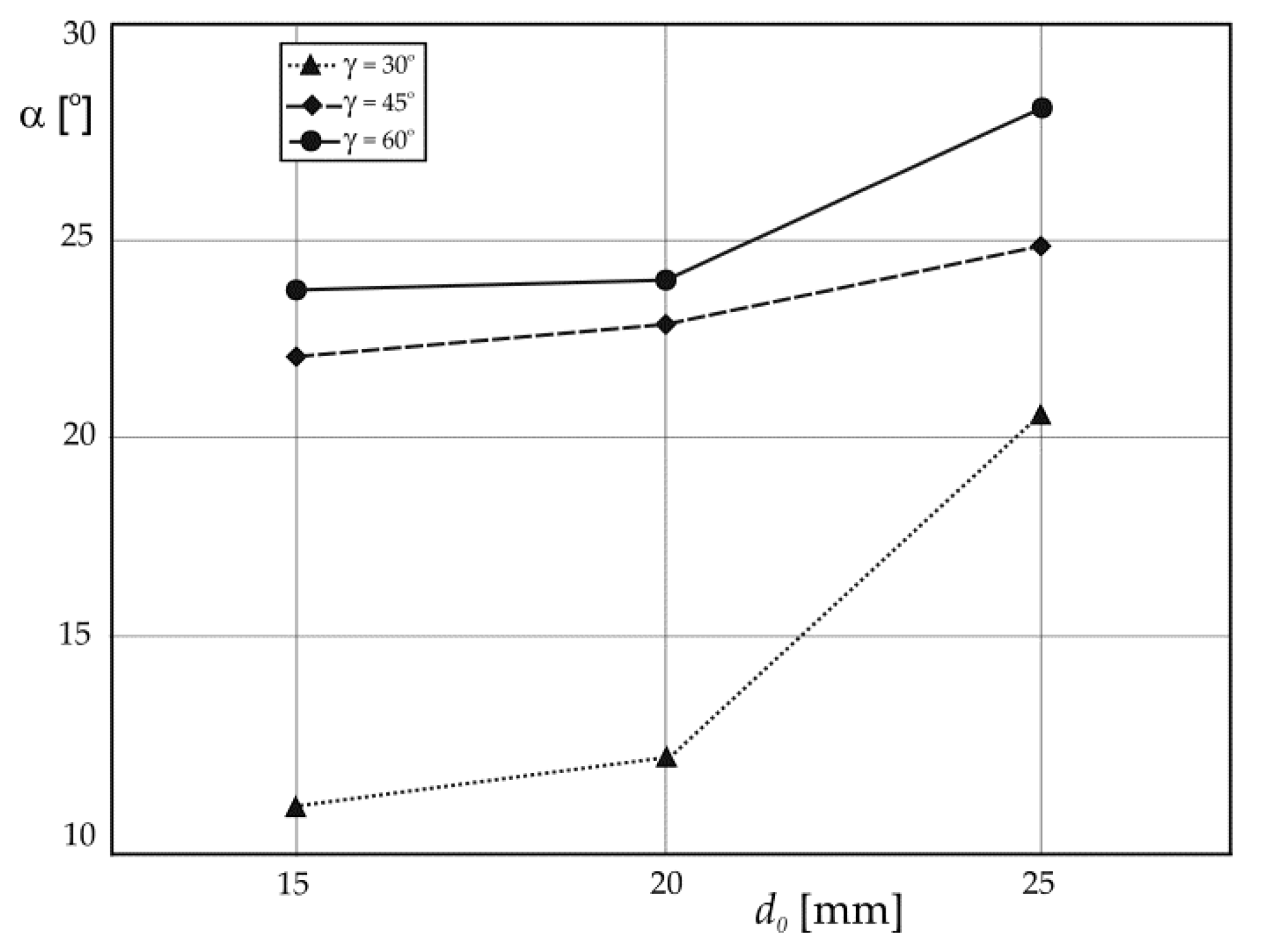
In the work [54] it was observed that the spray angle significantly depends on the diameter of the atomizer’s outlet opening. It has been shown that with the increase in the opening diameter, the spray angle value increases (Figure 13). The authors of the work [7] reached the same conclusions.
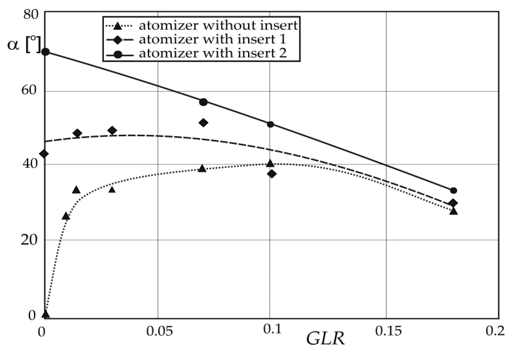
The research carried out by Jedelsky et al. [118] showed the influence of the atomizer design and GLR values on the size of the spray angle obtained as the result of carrying out the atomization process both in a standard effervescent atomizer and in an effervescent-swirl atomizer with a swirl insert (Figure 14). The subject of the atomization were suspensions. The dimensions of the individual components of the device are summarized in Table 2.
Figure 15 presents the relationship between the spray angle and GLR for both analyzed atomizers [118]. Based on the analysis of the diagram, it can be noticed that in the case of GLR ≈ 0, large values of the spray angle are obtained for atomizers equipped with a swirling element (atomizers I and II). When analyzing the dependence curve obtained for atomizer I, an increasing tendency of the spray angle with the increase of the GLR value, to the maximum value of about 0.006 can be noticed. Then, a further increase in the GLR value leads to a decrease in the value of the angle under analysis.
The situation is different in the case of atomizer II, where a downward trend in the size of the spray angle with the increase in GLR value can be observed. The downward nature of the dependence curve α on GLR was also observed in the case of an effervescent atomizer without a swirl insert, where at GLR ≈ 0 the atomizer produced an angle of approximately 0°. In turn, for GLR = 0.1, the maximum spray angle value was obtained, which was 40°. It is also worth emphasizing that the research showed that the sprayed liquid stream took the form of a hollow cone.

2.5. Droplet Diameter

The paper [66] describes a model that enables the estimation of the average diameter of sprayed liquid droplets at specific physico-chemical properties of the sprayed liquid and set GLR values. The analysis of the performed experimental tests showed that the change in volume causes the expansion of the cone of liquid flowing from the device outlet opening. During the analysis of the results, it was assumed that the total energy introduced into the volume is the same as the total energy exiting the system. It is worth adding that the total energy introduced into the volume was assumed to be the sum of the gas energy, the kinetic energy of the liquid and the surface energy of the gas bubbles embedded in the liquid. Finally, the following correlation equation was proposed to enable the determination of the SMD values:
S M D = 12 σ c ρ c { w c 2 + κ G L R w g 2 [ ( w c + κ 1 G L R w g ) 2 ] ( 1 + κ 1 G L R ) }
where wc is the liquid velocity, and wg is the gas velocity, which were measured across the atomizer outlet opening cross-section. The value of the coefficient κ1 was determined based on the experimental data. It should be emphasized that Equation (10) is correct for certain conditions, where M ˙ g , M ˙ c > 1.5 g/s, P < 336 kPa, and GLR < 0.02. Equation (10) proposed by Buckner and Sojek takes into account the deviations of the values determined from the model from the experimental values of ≤25% [66].
A different correlation equation allowing to determine the value of the mean droplet diameter was proposed in paper [55]. This equation includes the knowledge of the gas and liquid mass flow rate, the physico-chemical properties of the liquid, and the geometry of the atomizer outlet opening. This equation is compatible with the research carried out by Santangelo and Sojki [120,121], where the analysis of structure stability was used to estimate the size of the sprayed liquid droplets formed. For this model it was assumed that the two-phase gas and liquid mixture leaves the atomizer in the form of an air core surrounded by an annular layer of liquid. This layer breaks down into streams and films of liquid, which then break down forming droplets. The authors of the work [44,55] used the correlations published in the subject literature in order to determine the part of the gas-filled cross-section and the gas-liquid inter-phase slip in the annular flow. Lund et al. [55] initially estimated the thickness of the annular layer of liquid, and then concluded that it is divided into several cylindrical streams called ligaments, of the same diameters as the thickness of the liquid ring. In order to determine the size of streams and droplets, the stability analysis described by Weber [122] was used, which concerns the breakup of liquid ligaments [123]. The size of the formed droplets was determined on the basis of the assumption that each object stabilizes and forms a single droplet. The aspect of secondary atomization has been omitted. Therefore, the authors of the paper [55] obtained the following expression:
S M D = [ 3 2 2 π d l 3 ( 1 + 3 η c ρ c σ c d l ) 1 / 2 ] 1 / 3
where dl is the diameter of the liquid ligament, the value of which is compared to the thickness of the liquid film, thanks to which the following relationship [124] is obtained:
d l = 0.18 ( G L R V ˙ c ρ c ρ g ) 0.62
It should be noted that the equation proposed by Lund et al. (11) is particularly interesting due to the fact that it is entirely based on the fundamental principles of conservation of energy and momentum and does not contain any empirical constants. The accuracy of the proposed expression increases with increasing GLR value. Droplet size is estimated with an accuracy of 25% (with GLR < 0.02) and with an accuracy of about 5% (with GLR > 0.04). In this model, the aerodynamic effects of the gas surrounding the ligaments of liquid were not taken into account. During the two-phase atomization process, there is always a relative velocity between the atomizing gas and the liquid, called the inter-phase slip, which may ultimately have a significant impact on the liquid stream breakup [55].
Sutherland et al. [40] improved the model proposed by Lund et al. [55] by taking into account the relative velocity between the dosed gas and the liquid, as well as replacing the Weber stability analysis [122] with the Sterling and Sleicher stability analysis [125]. In the work [40], measurements of the atomized liquid momentum were performed in order to determine the velocity of the atomized gas and liquid at the device outlet. The model described by the authors of the work [40] also includes changes in the mean diameter of droplets as a result of changes in the viscosity of the liquid, surface tension, injection pressure, the ratio of the mass flow rate of gas to liquid, as well as the pore size of a given atomizer insert.
Sovani et al. [126,127] also made an attempt to improve the model proposed by Lund et al. [55] to estimate the probability of the distribution of the size of the generated spray droplets at the outlet of the atomizer. It is known that each atomizer generates droplets of different sizes, which depends on many factors that we can control as well as on various random phenomena that take place during atomization and we have no influence on them. The authors of the work [126,127] took into account just these random phenomena in the model of Lund et al. [55] as changes in the relative velocity of gas and liquid and physical properties of the liquid. The random changes included in the equation took the form of the probability distribution function (PDF for short) and the size distribution of the droplets of the generated spray. The results obtained on the basis of the proposed new model prove that the width of the droplet size distribution is a non-linear function of the variables and the relative velocity of the gas and liquid. Additionally, it was shown that changes in the physical properties of liquids did not have a significant effect on the droplet size distribution.
Liu et al. [128] described that the effervescent atomization was unstable at a small GLR while the atomization process proved gradually by increasing the GLR values. On the basis of the conducted research, it was determined the optimal atomization region, which was at a GLR equals 0.1. In [128], it described that the design parameters of atomizer have significant influence on SMD and atomization cone angle. The method of phase Doppler analyzer points out that the velocity and Sauter mean diameter distributions of the droplets are symmetrical on the discharge orifice center for analyzed swirl atomizers.
Kourmatzis et al. [129] described the near-field characteristics of effervescent sprays are examined by the used a method of the advanced image processing. The researches provide new quantitative insights into the character of the regime transitions that occur as a function of the GLR. The obtained research results prove that character of the distribution is variable and depends on the gas-to-flow ratio, where the distribution of the outer diameter of the ejected air laden liquid jet shows a bimodal character at low GLR equal to <0.5%, and mono-modal character at higher GLRs values.
Panchagnula and Sojka [57] developed their own model allowing to estimate the velocity profile of droplets in a sprayed liquid. This model concerned atomization of a turbulent stream of liquid. It was based on the velocity profile equation taken from the work [130].
In the work [131], research on atomizing a liquid was carried out using an unusual design of an atomizer with colliding inside it streams of gas, which then floats the liquid. The obtained test results showed different relationships than in the previous studies, because it was shown that with the increase in the diameter of the atomizer outlet opening and the inclination angle of the inlet wall of the atomizer outlet, the value of the mean surface-volume diameter decreases. The authors of the work [131] proposed the following correlation equation:
S M D = ( 4.4 0.4 d 0 ) ( tan φ ) 0.4 ( P g + 0.3 P c + 2.3 ) ( 6.3 + 2.6 d 0 0.4 d 0 2 )
The work [62] also included experimental analysis of the process of liquid spraying in terms of the impact of the atomizer design and the gas and liquid flow rate on the size of the spray droplets generated. The results of the research proved that SMD decreases with the increase of the diameter of the atomizer outlet opening and the liquid flow rate [45,62]. In the analysis of the obtained results, the equation proposed in the work [132] was used:
S M D = B ( W e g G L R ) A
where the power exponent A was –0.12, and the constant B referred to the internal geometry of the atomizer, the value of which was 2.465 × 10⁻³ m for d0 = 3 mm and 2.249 × 10⁻³ m for d0 = 4 mm.
Mulhelm et al. [133] also used the formula (14) proposed by Harari and Shera [132] to determine SMD. However, in their case, the A value was −0.4, and the B value was dependent on the properties of the liquid and the diameter of the atomizer. In order to estimate the relationship between the constant B and the physical properties of the liquid, the Ohnesorge number and the atomizer geometry (or more precisely: the diameter of the atomizer outlet opening) were used. In the case of SMD, the relationship between the B/d0 ratio and the Ohnesorge number takes the following form:
B d 0 = 0.21 O h 0.0622
After carrying out appropriate transformations, a correlation equation was obtained in the form:
S M D = 0.21 O h 0.0622 ( W e g G L R ) 0.4
A very good match between the experimental data and the correlation data was obtained from the dependence [62]:
S M D = 1.35 × 10 3 [ G L R ( d 0 D )   ] 0.26
It is worth paying attention to two issues, Equation (17) takes into account the diameter of the mixing chamber amounting to 0.02 m and the fact that it is valid only for the analyzed atomizer designs.
Hammad et al. [46] proved that the internal flow significantly controls the spray character and proposed a correlation equation taking into account the relationship between the Sauter mean diameter and the internal flow transition parameter (WeLS/Φih−0.314):
S M D d o = 1.42 1 + e ( 1.08 ( W e L S i h 0.314 ) ) / 0.8355 0.252
where Φih is liquid/gas momentum ratio per liquid injection hole, WeLS is Weber number of liquid superficial, and a correlation coefficient R2 equals to 0.75.
Yet another form of the correlation equation was proposed by Ramamurthi et al. [97], where the Sauter diameter also depends on the mass flow rate of gas and liquid and the Reynolds number:
S M D = 2.61 × 10 3 [ G L R ( R e c )   ] 0.66
Equation (19) is valid for annular flow and Rec < 10000. For the bubbly flow, the equation takes a modified form [97]:
S M D = 4 × 10 12 [ R e c ( G L R ) 0.5   ] 1.14
true for GLR values in the range of 0.005 to 0.04 and for Rec values from 10,000 to 15,000.
In the work [111], a correlation equation was proposed for the determination of the SMD value of a spray created as a result of spraying aqueous silica solutions (Aerosil 300):
S M D = 9.79 × 10 4 ( W e g G L R ) 0.11
This equation is correct when the following assumptions are met: Aerosil 300 concentration in the solution is <4%, d0 = 0.0017 m, Weg value ranges from 80 to 1700, and GLR ranges from 0.014 to 0.46.
Broniarz-Press et al. [45] conducted research related to the process of spraying aqueous solutions of poly (ethylene oxide) with molar mass from 1 × 10⁶ to 8 × 10⁶ kg/kmol. The tested aqueous polymer solutions showed the characteristics of non-Newtonian liquids. Based on the conducted research, the authors proposed a correlation equation in the form:
S M D = 1.2 × 10 2 d 0 M w 0.25 G L R 0.23
where MW is the average molar mass of the polymer. This equation is valid when d 0 ( 0.003 ; 0.006 ) m and G L R ( 0.028 ; 0.92 ) .
On the other hand, in the work [110], the study of the atomization of liquids with different rheological properties was carried out, which showed the same dynamic viscosity (at shearing), and were different in longitudinal viscosity (at stretching). The analysis of the obtained tests showed a clear influence of longitudinal viscosity both on the change of the internal and external flow structure and on the increase in the diameter of the formed droplets [110,134,135]. The literature on the subject describes that the longitudinal viscosity also significantly affects the spray angle. The mathematical analysis of the obtained results allowed to estimate the relationship:
S M D = f ( η e 0.28 )
Figure 16 shows a diagram of the effervescent atomization process and the structure of the effervescent atomizer used in the research by Qian et al. [72,136]. On the basis of the figure illustrating the course of the atomization process, three main stages can be distinguished: atomization with internal mixing (a two-phase system is formed: gas bubbles in the liquid), primary breakup (breakup of the liquid into small drops), and secondary breakup (the resulting drops are subjected to a series of events, i.e., collisions, breakup, coalescence).
A comprehensive three-dimensional model including primary and secondary breakup is described in the works [72,136]. This model was used to estimate the diameter of droplets with the value smaller than the diameter of the atomizer outlet opening. In order to describe the gas phase, the mean values of Re from the Navier-Stokes equation (k-ε model) were used, while the phase of the dispersed droplets was presented as Lagrange elements in relation to physical phenomena [72,137].
Accordingly, Lin et al. [137] and Qian et al. [72] obtained the equation taking into account the secondary breakup of droplets of the form:
S M D = 0.038 ( G L R 0.12 ) 0.4787 ( P i n 4 × 10 6 ) 0.1639 ( d 0 0.2 ) 0.7039 + 10 3 ( k y + S M D w )   [ m m ]
where y is the axial distance, the k-factor defines the operating parameters of the atomizer. In Equation (24), the first segment is related to the primary atomization and the second segment is related to the SMD change along with the axial distance from the outlet opening. In turn, the third segment of the equation (SMDw value) determines the change in SMD value during secondary atomization. However, it should be remembered that the proposed equation includes variables and constants limiting its application.
In order to determine a convenient mathematical description, the effervescent atomization process underwent modelling based on the appropriate Navier-Stokes equations combined with the particle monitoring method. Furthermore, the external gas flow was assumed to be a turbulent flow. This model also takes into account primary and secondary breakup, and the average diameter of spray droplets was estimated with the use of various operating conditions and properties of the sprayed liquid [72]. Qian et al. [72] finally proposed three correlation equations to estimate the value of the mean surface-volume diameter:
-
immediately at the atomizer outlet opening:
S M D ( y 0 ) = 0.00505 ( G L R 0.12 ) 0.4686 ( P i n 5 × 10 6 ) 0.1805 ( d 0 0.2 ) 0.6675 ( η c 0.2 ) 0.1714 ( σ 46 ) 0.1382
-
in a situation where the distance from the atomizer outlet is small and does not exceed 10 mm:
S M D ( 0 < y < 10 ) = 10 4 y [ 1.103 ( G L R 0.12 ) 0.218 + 14.72 ( G L R 0.12 ) 0.3952 ( η c 0.2 ) 0.1571 ( σ 46 ) 0.8199   ] + + 0.00505 ( 1 y ) ( G L R 0.12 ) 0.4686 ( P i n 5 × 10 6 ) 0.1805 ( d 0 0.2 ) 0.6675 ( η c 0.2 ) 0.1714 ( σ 46 ) 0.1382
-
when the distance from the atomizer outlet is greater than 10 but less than 200 mm:
S M D ( 10 < y < 200 ) = 10 4 [ 1.103 y ( G L R 0.12 ) 0.218 + 14.72 ( G L R 0.12 ) 0.3952 ( η c 0.2 ) 0.1571 ( σ 46 ) 0.8199 ]
As can be seen, in Equations (25)–(27) an important role is played by the value y, which defines the distance from the atomizer outlet opening. In order to clarify the notation of the equations, it is worth adding that in the above equations the values of y and d0 are defined in centimeters, Pin in grams per centimeter and square of a second, ηc in grams per centimeter and second, and σ in grams per square of a second.
In the work [138], a three-dimensional model of liquid droplets and gas bubbles in a two-phase flow was described. The authors of the work conducted research on the development of the atomized liquid structure along the atomizer outlet opening. It was evidenced in the work that GLR is one of the most important parameters enabling the control of the atomization process, and the increase in the value of this ratio contributes to a gradual reduction in the size of the analyzed droplets. Moreover, it has been proven that the use of a smaller atomizer outlet opening promotes primary breakup and that high injection pressure has a greater effect on the secondary breakup of the drops.
The internal geometry of the atomizer also plays an important role in the atomization process. It determines the nature of the internal flow of gas and liquid and can significantly affect the efficiency of the entire process. The conducted studies of the influence of the size and number of aerator holes on the average droplet size proved that the use of an aerator with many holes leads to a slightly narrower diameter distribution in relation to the aerator with one hole and the same effective area of gas inlet openings. However, this phenomenon is not fully understood and explained [68].
On the basis of the mean value of the droplet velocity and the distribution of their velocity, it is possible to determine the effectiveness of the process [8,56]. Based on the conducted research, Panchagnula and Sojka [57], Sankar et al. [139], and Jedelsky et al. [106] concluded that the droplet velocity increases as a result of the increase in the set injection pressure. A steady increase in the droplet velocity with the increase in GLR value was also observed. It has also been found that the use of higher mass gas flow rates leads to droplets acceleration [106,137]. The literature review indicates that the value of the droplet velocity reaches its maximum in the aerosol axis (y = 0), and it quickly decreases with the increase of the axial distance from the atomizer and the increase of the radial distance from the aerosol axis [40,57,106,137,140,141,142]. The highest mass flow rate is observed in the axis of the generated spray [115]. Lund et al. [116] analyzed the effect of gas molecular weight on droplet velocity and proved that droplet velocity decreases due to an increase in gas molecular weight.
Numerous studies published in the papers have shown that the use of a polymer additive to the sprayed liquid contributes to the reduction in the number of average droplets, and thus to the increase in the number of droplets with large diameters [7,45,143,144]. In turn, the number of small droplets decreases as a result of an increase in the concentration of the polymer and its molar mass [144]. This phenomenon is important from the practical point of view, because, for example, in agrotechnical spraying processes, droplets with very small diameters are undesirable due to the fact that they can be easily moved by the wind [144], as well as in the process of reducing spontaneous combustion of fuels carried out during emergency landings in aviation [14]. Zhu et al. [145] proved that the mean droplet diameter increases with the increase in the dynamic viscosity of the liquid. Mun et al. [144] also observed some discrepancies in conducted research. They showed that, depending on the type of atomizer used for spraying a 50% aqueous solution of glycerin, a lower, the same, or higher value of the average droplet diameter was obtained with regard to water. This proves that, based on the literature data, it is difficult to unambiguously determine the effect of the change in liquid viscosity on the mean droplet diameter.
It is worth emphasizing, however, that on the basis of all correlation equations proposed in the literature, it appears that the value of the Sauter’s mean diameter decreases as a result of the increase in GLR value. However, it should be remembered that the influence of the atomizer outlet opening diameter on this value was not taken into account in all cases. It has been shown, in turn, that the longitudinal viscosity of the sprayed liquid is a very important factor influencing the value of the mean surface-volume diameter [7,109]. The increase in the longitudinal viscosity of the sprayed liquid contributes to the increase in the size of the droplets of the spray produced. This is confirmed by the research by Zhu et al. [145], carried out with the use of hydraulic atomizers for spraying. In the work [145] it was evidenced that the droplet diameter increases in a non-linear manner with the increase in the longitudinal viscosity (according to the power function with an exponent of 0.15). This was also confirmed by the studies published in the work [146]. The authors of this work subjected aqueous solutions containing polyacrylamide to the atomization process. In the work [7], a correlation equation was proposed that allows to determine the SMD value based on the formula:
S M D = C d 0 1.12 M ˙ c 0.64 G L R 0.80 W e g 0.21 O h 0.06 ( η c η w a t e r ) 0.16 T r 0.28   [ m ]
where C is a parameter (with a value of 6.98 × 10⁻⁴) depending on the internal geometry of the atomizer and other parameters affecting the mean diameter of the droplets (however, it should be remembered that their influence has not been analyzed). Equation (28) is the first one that covers the longitudinal viscosity of the atomized liquid.
The purpose of this article is to summarize the results obtained from scientific researches of effervescent-swirl atomizers performance embracing wide variations in atomizer design, liquid properties, and operating conditions. The results of research on atomizers of this type may contribute to the spread of their use and suggest possible areas for future practical applications, including completely new areas.

3. Conclusions

The paper presents the theoretical basis of the atomization process, the use of atomizers, and an analysis of the collected literature data. Effervescent-swirl atomizers were characterized. The authors of the work, on the basis of the literature review, analyzed the results of research related to, inter alia, the phenomenon of air core formation and the influence of a number of parameters on the efficiency of the atomization process. This work includes the analysis of the results of the research on the influence of gas and liquid flow rates; injection pressure, or the dimensions and design of the atomizer, the shape of the outlet opening, and the physicochemical properties of the atomized liquid on the pressure drop, discharge coefficient, spray angle, droplet size, quantitative distributions, and mean volume-surface diameter. The paper presents correlation equations covering the basic features of the atomization process, which bind a large number of parameters affecting the efficiency of the atomization process and the nature of the spray produced, which may be useful in design practice.
An ability to predict atomizer performance is desired since it would significantly reduce time and cost in the design process. To the areas that we feel warrant further investigations belongs:
-
Because, a comprehensive model of the atomization process is not yet available, there is considerable scope for efforts to model the subprocesses involved in effervescent-swirl atomization and to integrate them into a comprehensive model;
-
Due to different and different physico-chemical properties, the atomization of non-Newtonian liquids, suspensions and liquid metals should be tested;
-
In the future, it would be necessary to investigate and analyze the impact of various independent parameters on the unsteadiness of effervescent-swirl sprays, fluid mechanics of effervescent-swirl atomization, and perform modeling (CFD) of the process.
Further work is necessary to gain a deeper understanding of the fundamental mechanisms and two-phase flow phenomena involved in effervescent-swirl atomization.

Author Contributions

Conceptualization, M.O., M.M., K.C., and S.W. (Stanisław Witczak); formal analysis, S.W. (Stanisław Witczak), K.C., M.M., S.W. (Sylwia Włodarczak), A.K., and M.H.; writing—original draft, M.M., M.O., K.C., and S.W. (Stanisław Witczak). All authors have read and agreed to the published version of the manuscript.

Funding

This research was funded by the Ministry of Education and Science of Poland.

Institutional Review Board Statement

Not applicable.

Informed Consent Statement

Not applicable.

Data Availability Statement

The data presented in this study are available in the article.

Acknowledgments

The study was supported by the Ministry of Education and Science of Poland.

Conflicts of Interest

The authors declare no conflict of interest.

References

  1. Ochowiak, M. Koncepcja atomizera pęcherzykowo-wirowego z analizą oporów przepływu. Inżynieria Apar. Chem. 2012, 51, 360–361. [Google Scholar]
  2. Lefebvre, A.; McDonell, V. Atomization and Sprays; CRC Press Taylor & Francis Group: Boca Raton, FL, USA, 2017. [Google Scholar]
  3. Tonini, S.; Conti, P.; Cossali, G.E. Numerical modelling of internal flow in water mist injectors: Effect of nozzle geometry and operating conditions. Fire Technol. 2019, 55, 2395–2417. [Google Scholar] [CrossRef]
  4. Ochowiak, M.; Krupińska, A.; Włodarczak, S.; Matuszak, M.; Markowska, M.; Janczarek, M.; Szulc, T. The two-phase conical swirl atomizers: Spray characteristics. Energies 2020, 13, 3416. [Google Scholar] [CrossRef]
  5. Lefebvere, A.H. Atomization and Sprays; Hemisphere Publishing Corporation: New York, NY, USA, 1989. [Google Scholar]
  6. Orzechowski, Z.; Prywer, J. Wytwarzanie i Zastosowanie Rozpylonej Cieczy; WNT: Warszawa, Poland, 2008. (In Polish) [Google Scholar]
  7. Ochowiak, M. Analiza Procesu Rozpylania Cieczy w Rozpylaczach Pęcherzykowych i Pęcherzykowo-Wirowych; Habilitation Thesis; WPP; Poznan University of Technology: Poznań, Poland, 2014; p. 519. (In Polish) [Google Scholar]
  8. Sovani, S.D.; Sojka, P.E.; Lefebvere, A.H. Effervescent atomization. Prog. Energy Combust. Sci. 2001, 27, 483–521. [Google Scholar] [CrossRef]
  9. Dhivyaraja, K.; Gaddes, D.; Freeman, E.; Tadigadapa, S.; Panchagnula, M.V. Dynamical similarity and universality of drop size and velocity spectra in sprays. J. Fluid Mech. 2019, 860, 510–543. [Google Scholar] [CrossRef]
  10. Jarrahbashi, D.; Sirignano, W.A.; Popov, P.P.; Hussain, F. Early spray development at high gas density: Hole, ligament and bridge formations. J. Fluid Mech. 2016, 792, 186–231. [Google Scholar] [CrossRef] [Green Version]
  11. Chaussonnet, G.; Geppertha, S.; Holza, S.; Kocha, R.; Bauera, H.J. Influence of the ambient pressure on the liquid accumulation and on the primary spray in prefilming airblast atomization. Int. J. Multiph. Flow 2020, 125, 1–24. [Google Scholar] [CrossRef] [Green Version]
  12. Shao, C.; Luo, K.; Chal, M.; Fan, J. Sheet, ligament and droplet formation in swirling primary atomization. AIP Adv. 2018, 8, 045211. [Google Scholar] [CrossRef]
  13. En’urga Inc. High Flow Rate Effervescent Atomizer. Available online: www.enurga.com (accessed on 12 October 2010).
  14. Orzechowski, Z.; Prywer, J. Rozpylanie Cieczy w UrząDzeniach Energetycznych; WNT: Warszawa, Poland, 1994. (In Polish) [Google Scholar]
  15. Patil, D.P.; Laskowski, J.S. Development of zero conditioning procedure for coal reverse flotation. Miner. Eng. 2008, 21, 373–379. [Google Scholar] [CrossRef]
  16. Tricou, C.; Knasiak, K.F. Development of a High Transfer Efficiency Painting Technology Using Effervescent Atomization. In Proceedings of the ILASS–Americas, 18th Annual Conference on Liquid Atomization and Spray Systems, Irvine, CA, USA, 22–25 May 2005. [Google Scholar]
  17. Petersen, F.J.; Worts, O.; Schaefer, T.; Sojka, P.E. Design and atomization properties for and inside-out type effervescent atomizer. Drug Dev. Ind. Pharm. 2004, 30, 319–326. [Google Scholar] [CrossRef]
  18. Petersen, F.J.; Wørts, O.; Schaefer, T.; Sojka, P.E. Effervescent atomization of aqueous polymer solutions and dispersions. Pharm. Dev. Technol. 2001, 6, 201–210. [Google Scholar] [CrossRef] [PubMed]
  19. Piątkowski, M.; Zbiciński, I. Płomieniowe suszenie rozpyłowe. Inżynieria I Apar. Chem. 2010, 49, 87–88. (In Polish) [Google Scholar]
  20. Petersen, F.J. A New Approach for Pharmaceutical Sprays. Effervescent Atomization. Atomizer Design and Spray Characterization. Ph.D. Thesis, Department of Pharmaceutics, The Danish University of Pharmaceutical Sciences, Copenhagen, Danmark, 2004. [Google Scholar]
  21. O’Sullivan, J.J.; Norwood, E.A.; O’Mahony, J.A.; Kelly, A.L. Atomisation technologies used in spray drying in the dairy industry: A review. J. Food Eng. 2019, 243, 57–69. [Google Scholar] [CrossRef]
  22. Jayapal, S.; Kadiresh, R.M. Spray characteristics of plug type swirl injector. In Proceedings of the Advances in Science and Engineering Technology International Conferences (ASET), Dubai/Sharjah/Abu Dhabi, United Arab Emirates, 6 February–5 April 2018. [Google Scholar]
  23. Kim, K.; Lim, O. Investigation of the spray development process of gasoline-biodiesel blended fuel sprays in a constant volume chamber. Energies 2020, 13, 4819. [Google Scholar] [CrossRef]
  24. Panchasara, H.; Ashwath, N. Effects of pyrolysis bio-oils on guel atomization—A review. Energies 2021, 14, 794. [Google Scholar] [CrossRef]
  25. Kim, H.Y.; Ge, J.C.; Choi, N.J. Effects of fuel injection pressure on combustion and emission characteristics under low speed conditions in a diesel engine fueled with palm oil biodiesel. Energies 2019, 12, 3264. [Google Scholar] [CrossRef] [Green Version]
  26. Holz, S.; Braun, S.; Chaussonnet, G.; Koch, R.; Bauer, H.J. Close nozzle spray characteristics of a prefilming airblast atomizer. Energies 2019, 12, 2835. [Google Scholar] [CrossRef] [Green Version]
  27. Shinjo, J. Recent advances in computational modeling of primary atomization of liquid fuel sprays. Energies 2018, 11, 2971. [Google Scholar] [CrossRef] [Green Version]
  28. Payri, R.; García-Oliver, J.M.; Mendoza, V.; Viera, A. Analysis of the influence of diesel spray injection on the ignition and soot formation in multiple injection strategy. Energies 2020, 13, 3505. [Google Scholar] [CrossRef]
  29. Liu, C.; Liu, F.; Yang, J.; Mu, Y.; Hu, C.; Xu, G. Experimental investigations of spray generated by a pressure swirl atomizer. J. Energy Inst. 2019, 92, 210–221. [Google Scholar] [CrossRef]
  30. Lee, M.Y.; Lee, G.S.; Kim, C.J.; Seo, J.H.; Kim, K.H. Macroscopic and microscopic spray characteristics of diesel and gasoline in a constant volume chamber. Energies 2018, 11, 2056. [Google Scholar] [CrossRef] [Green Version]
  31. Fan, X.; Liu, C.; Mu, Y.; Wang, K.; Wang, Y.; Gang Xu, G. Experimental investigations of flow field and atomization field characteristics of pre-filming air-blast atomizers. Energies 2019, 12, 2800. [Google Scholar] [CrossRef] [Green Version]
  32. Isa, K.M.; Osman, K.; Yahya, A.; Ghaffar, Z.A.; Hamid, A.H.A.; Kasolang, S. Studies on the spray characteristics of pressure-swirl atomizers for automatic hand sanitizer application. J. Adv. Res. Fluid Mech. Therm. Sci. 2019, 55, 51–64. [Google Scholar]
  33. Golovanevsky, B.; Levy, Y. Fluid Image Velocimetry of the Flow in the Recirculation Zone of a Bluff Body Stabilized and Controlled Burner. In Proceedings of the 10th International Symposium on Applications of Laser Techniques to Fluid Mechanics, Lisbon, Portugal, 10–13 July 2000; pp. 1–10. [Google Scholar]
  34. Golovanevsky, B.; Levy, Y. Suppression of Combustion Instability Using an Aerodynamically Exited Atomizer. In Proceedings of the 11th International Symposium on Applications of Laser Techniques to Fluid Mechanics, Lisbon, Portugal, 8–11 July 2002; pp. 1–14. [Google Scholar]
  35. Sovani, S.D.; Chou, E.; Sojka, P.E.; Gore, J.P.; Eckerle, W.A.; Crofts, J.D. High pressure effervescent atomization: Effect of ambient pressure on spray cone angle. Fuel 2001, 80, 427–435. [Google Scholar] [CrossRef]
  36. Sovani, S.D.; Crofts, J.D.; Sojka, P.E.; Gore, J.P.; Eckerle, W.A. Structure and steady-state spray performance of an effervescent diesel injector. Fuel 2005, 84, 1503–1514. [Google Scholar] [CrossRef]
  37. Spicher, U. Direkteinspritzung im Ottomotor, III: Forschungsergebnisse und Aktueller Entwicklungsstand bei der Benzin-Direkteinspritzung; Expert Verlag: Renningen, Germany, 2001. [Google Scholar]
  38. Wu, S.R.; Cheng, W.C.; Chiao, J. Low NOx heavy fuel oil combustion with high temperature air. Fuel 2007, 86, 820–828. [Google Scholar] [CrossRef]
  39. Yu, G.; Li, J.G.; Zhao, J.R.; Yue, L.J.; Chang, X.Y.; Sung, C.J. An experimental study of kerosene combustion in a supersonic model combustor using effervescent atomization. Proc. Combust. Inst. 2005, 30, 2859–2866. [Google Scholar] [CrossRef]
  40. Sutherland, J.J.; Sojka, P.E.; Plesniak, M.W. Entrainment by ligament-controlled effervescent atomizer-produced sprays. Int. J. Multiph. Flow 1997, 23, 865–884. [Google Scholar] [CrossRef]
  41. Gong, J.S.; Fu, W.B. The experimental study on the flow characteristics for swirling gas-liquid spray atomizer. Appl. Therm. Eng. 2007, 27, 2886–2892. [Google Scholar] [CrossRef]
  42. Chin, J.S.; Lefebvre, A.H. A design procedure for effervescent atomizers. J. Eng. Gas Turbines Power 1995, 117, 226–271. [Google Scholar] [CrossRef]
  43. Sher, E.; Bar-Kohany, T.; Rashkovan, A. Flash-boiling atomization. Prog. Energy Combust. Sci. 2008, 34, 417–439. [Google Scholar] [CrossRef]
  44. Ochowiak, M.; Broniarz-Press, L.; Różański, J. The discharge coefficient of effervescent atomizers. Exp. Therm. Fluid Sci. 2010, 34, 1316–1323. [Google Scholar] [CrossRef]
  45. Broniarz-Press, L.; Ochowiak, M.; Woziwodzki, S. Atomization of PEO aqueous solutions in effervescent atomizers. Int. J. Heat Fluid Flow 2010, 31, 651–658. [Google Scholar] [CrossRef]
  46. Hammad, F.A.; Sun, K.; Che, Z.; Jedelsky, J.; Wang, T. Internal two-phase flow and spray characteristics of outside-in-liquid twin-fluid atomizers. Appl. Therm. Eng. 2021, 187, 116555. [Google Scholar] [CrossRef]
  47. Kourmatzis, A.; Lowe, A.; Masri, A.R. Combined effervescent and airblast atomization of a liquid jet. Exp. Therm. Fluid Sci. 2016, 75, 66–76. [Google Scholar] [CrossRef]
  48. Jedelský, J.; Jícha, M. Spray characteristics and liquid distribution of multi-hole effervescent atomisers for industrial burners. Appl. Therm. Eng. 2016, 96, 286–296. [Google Scholar] [CrossRef] [Green Version]
  49. Chen, B.; Gao, D.; Li, Y.; Chen, C.; Yuan, X.; Wang, Z.; Sun, P. Investigation of the droplet characteristics and size distribution during the collaborative atomization process of a twin-fluid nozzle. Int. J. Adv. Manuf. Technol. 2020, 107, 1625–1639. [Google Scholar] [CrossRef]
  50. Ghaffar, Z.A.; Kasolang, S.; Hussein, A.; Hamid, A. Characteristics of swirl effervescent atomizer spray angle. Appl. Mech. Mater. 2014, 607, 108–111. [Google Scholar] [CrossRef]
  51. Ghaffar, Z.A.; Kasolang, S.; Hussein, A.; Hamid, A.; Ahmed, D.I.; Sainan, K.I.; Roselina, N.; Roseley, N. Gas core characteristics of swirl effervescent atomizer. J. Teknol. 2015, 76, 58–62. [Google Scholar]
  52. Ghaffar, Z.A.; Kasolang, S.; Hussein, A.; Hamid, A.; Chee Sheng, O.; Azlina, M.; Bakar, A. Effect of geometrical parameters interaction on swirl effervescent atomizer spray angle. J. Teknol. 2015, 76, 63–67. [Google Scholar]
  53. Chen, S.K.; Lefebvre, A.H. Spray cone angles of effervescent atomizers. At. Sprays 1994, 4, 291–301. [Google Scholar]
  54. Lefebvre, A.H.; Wang, X.F.; Martin, C.A. Spray characteristics of aerated-liquid pressure atomizers. J. Propuls. Power 1988, 4, 293–298. [Google Scholar] [CrossRef]
  55. Lund, M.T.; Sojka, P.E.; Lefebvre, A.H.; Gosselin, P.G. Effervescent atomization at low mass flow rates. Part 1: The influence of surface tension. At. Sprays 1993, 3, 77–89. [Google Scholar]
  56. Ochowiak, M.; Broniarz-Press, L. Atomization performance of effervescent atomizers with gas-liquid internal mixing. Pol. J. Chem. Technol. 2008, 10, 38–41. [Google Scholar] [CrossRef] [Green Version]
  57. Panchagnula, M.V.; Sojka, P.E. Spatial droplet velocity and size profiles in effervescent atomizer-produced sprays. Fuel 1999, 78, 729–741. [Google Scholar] [CrossRef]
  58. Whitlow, J.D.; Lefebvre, A.H. Effervescent atomizer operation and spray characteristics. At. Sprays 1993, 3, 137–156. [Google Scholar] [CrossRef]
  59. Whitlow, J.D.; Lefebvre, A.H.; Rollbuhler, J.R. Experimental studies on effervescent atomizers with wide spray angles. Advis. Group Aerosp. Res. Dev. Conf. Proc. 1993, 536, 1–11. [Google Scholar]
  60. Optimizing Your Spray System. Spray Nozzle Maintenance and Control for Improved Production Efficiency. In Proceedings of the ILASS–Americas, 17th Annual Conference on Liquid Atomization and Spray Systems, Irvine, CA, USA, 13–17 July 2003.
  61. Lefebvre, A.H. Twin-Fluid Atomization: Factors Influencing Mean Drop Size. In Proceedings of the 5th International Conference Liquid Atomization & Spray Systems, Gaithersburg, MD, USA, 15–18 July 1991; pp. 49–64. [Google Scholar]
  62. Ochowiak, M. Experimental study on effect of aqueous suspension of silica additives on the atomization process in effervescent nozzles. Chem. Process Eng. 2010, 31, 35–42. [Google Scholar]
  63. Jicha, M.; Jedelsky, J.; Otahal, J.; Slama, J. Influence of some geometrical parameters on the characteristics of effervescent atomization. In Proceedings of the 18th European Conference on Liquid Atomization and Spray Systems ILASS-Europe, Zaragoza, Spain, 9–11 September 2002; pp. 1–6. [Google Scholar]
  64. Lefebvre, A.H. Some recent developments in twin-fluid atomization. Part. Part. Syst. Charact. 1996, 13, 205–216. [Google Scholar] [CrossRef]
  65. Buckner, H.E.; Sojka, P.E. Effervescent atomization of high viscosity fluids. Part 1: Newtonian liquids. At. Sprays 1991, 1, 239–252. [Google Scholar] [CrossRef]
  66. Buckner, H.E.; Sojka, P.E. Effervescent atomization of high viscosity fluids. Part 2: Non-Newtonian liquids. At. Sprays 1993, 3, 157–170. [Google Scholar] [CrossRef]
  67. Chin, J.S.; Lefebvre, A.H. Flow patterns in internal-mixing, twin-fluid atomizers. At. Sprays 1993, 3, 463–475. [Google Scholar] [CrossRef]
  68. Wang, X.F.; Chin, J.S.; Lefebvre, A.H. Influence of gas injector geometry on atomization performance of aerated-liquid nozzles. Int. J. Turbo Jet Engines 1989, 6, 271–279. [Google Scholar] [CrossRef]
  69. Kim, H.G.; Yano, T.; Song, K.K.; Shuichi, T. Microscopic spray characteristics in the effervescent atomizer with two aerator tubes. Ksme Int. J. 2004, 18, 1661–1667. [Google Scholar] [CrossRef]
  70. Kushari, A. Effect of injector geometry on the performance of an internally mixed liquid atomizer. Fuel Process. Technol. 2010, 91, 1650–1654. [Google Scholar] [CrossRef]
  71. Li, J.; Lefebvre, A.H.; Rollbuhler, J.R. Effervescent atomizers for small gas turbines. Am. Soc. Mech. Eng. 1994, 78859, V003T06A048. [Google Scholar]
  72. Qian, L.; Lin, J.; Xiong, H. A fitting formula for predicting droplet mean diameter for various liquid in effervescent atomization spray. J. Therm. Spray Technol. 2010, 19, 586–601. [Google Scholar] [CrossRef]
  73. Ulbrich, R. Wykorzystanie Metod Analizy Obrazu do Oceny Nierównomierności Przepływu Gaz–Ciecz w Elementach Płaszczowo-Rurowego Wymiennika Ciepła; Oficyna Wydawnicza Politechniki Opolskiej: Opole, Poland, 2006. (In Polish) [Google Scholar]
  74. Zając, D.; Ulbrich, R. Nieinwazyjne Metody Badań Przepływów Dwufazowych Gaz–Ciecz; Oficyna Wydawnicza Politechniki Opolskiej: Opole, Poland, 2005. (In Polish) [Google Scholar]
  75. Jedelsky, J.; Maly, M.; Del Corral, N.P.; Wigley, G.; Janackova, L.; Jicha, M. Air–liquid interactions in a pressure-swirl spray. Int. J. Heat Mass Transf. 2018, 121, 788–804. [Google Scholar] [CrossRef] [Green Version]
  76. Bar-Kohany, T.; Levy, M. State of the art review of flash-boiling atomization. At. Sprays 2016, 26, 1259–1305. [Google Scholar] [CrossRef]
  77. Czernek, K. Hydrodynamiczne Aspekty Projektowania Aparatów Cienkowarstewkowych dla Cieczy Bardzo Lepkich; Oficyna Wydawnicza Politechniki Opolskiej: Opole, Poland, 2013. (In Polish) [Google Scholar]
  78. Dziubiński, M.; Prywer, J. Mechanika Płynów Dwufazowych; WNT: Warszawa, Poland, 2009. (In Polish) [Google Scholar]
  79. Orzechowski, Z. Przepływy Dwufazowe Jednowymiarowe Ustalone Adiabatyczne; PWN: Warszawa, Poland, 1990. (In Polish) [Google Scholar]
  80. Orzechowski, Z.; Prywer, J. Przepływy Dwufazowe; Wydawnictwo Politechniki Łódzkiej: Łódź, Poland, 1991. (In Polish) [Google Scholar]
  81. Orzechowski, Z.; Prywer, J. Rozpylanie Cieczy; WNT: Warszawa, Poland, 1991. (In Polish) [Google Scholar]
  82. Orzechowski, Z.; Prywer, J.; Zarzycki, R. Mechanika Płynów w Inżynierii Środowiska; WNT: Warszawa, Poland, 1997. (In Polish) [Google Scholar]
  83. Bhagwat, S.M. Study of Flow Patterns and Void Fraction in Vertical Downward Two Phase Flow. Master’s Thesis, Oklahoma State University, Tulsa, OK, USA, 2011. [Google Scholar]
  84. Rahman, M.A.; Balzan, M.; Heidrick, T.; Fleck, B.A. Effects of the gas phase molecular weight and bubble size on effervescent atomization. Int. J. Multiph. Flow 2012, 38, 35–52. [Google Scholar] [CrossRef]
  85. Hussein, A.; Hafiz, M.; Rashid, H.; Halim, A.; Wisnoe, W.; Kasolang, S. Characteristics of Hollow Cone Swirl Spray at Various Nozzle Orifice Diameters. Jurnal Teknologi 2012, 58, 1–4. [Google Scholar] [CrossRef] [Green Version]
  86. Różańska, S. Extensional viscosity of w/o emulsions. Procedia Eng. 2012, 42, 742–752. [Google Scholar] [CrossRef] [Green Version]
  87. Różańska, S.; Broniarz-Press, L.; Różański, J.; Mitkowski, P.; Ochowiak, M.; Woziwodzki, S. Extensional viscosity and stability of oil-in-water emulsions with addition poly(ethylene oxide). Procedia Eng. 2012, 42, 733–741. [Google Scholar] [CrossRef] [Green Version]
  88. Sutherland, J.J.; Sojka, P.E.; Plesniak, M.W. Ligament controlled effervescent atomization. At. Sprays 1997, 7, 383–406. [Google Scholar] [CrossRef]
  89. Asihmin, V.I.; Geller, Z.I.; Skobel’cyn, Y.A. Discharge of a real fluid from cylindrical orifices. Oil Ind. 1961, 9, 135–172. [Google Scholar]
  90. Broniarz-Press, L.; Ochowiak, M.; Różański, J.; Szaferski, W.; Woziwodzki, S. Przepływ Trójfazowy Gaz–Ciecz–Ciecz w Dyszach Rozpryskowych; Wydawnictwo Politechniki Poznańskiej: Poznań, Poland, 2010. (In Polish) [Google Scholar]
  91. Nakayama, Y. Action of the fluid in the air micrometer: First report, characteristics of small diameter nozzle and orifice. Bull. Jpn. Soc. Mech. Eng. 1961, 4, 516–524. [Google Scholar] [CrossRef]
  92. Koch, R.; Noworyta, A. Procesy Mechaniczne w Inżynierii Chemicznej; WNT: Warszawa, Poland, 1998. (In Polish) [Google Scholar]
  93. Marcinkowski, A.; Dziubiński, M. Discharge coefficient for discharge of non-newtonian liquids form vessel. Chem. Eng. Proc. 2004, 25, 1297–1302. (In Polish) [Google Scholar]
  94. Ochowiak, M. The experimental study on the viscosity effect on the discharge coefficient for effervescent atomizers. Exp. Therm. Fluid Sci. 2013, 50, 187–192. [Google Scholar] [CrossRef]
  95. Dafsari, R.A.; Lee, H.J.; Han, J.; Park, D.C.; Lee, J. Viscosity effect on the pressure swirl atomization of an alternative aviation fuel. Fuel 2019, 240, 179–191. [Google Scholar] [CrossRef]
  96. Chen, S.K.; Lefebvre, A.H. Discharge coefficients for plain-orifice effervescent atomizers. At. Sprays 1994, 4, 275–290. [Google Scholar]
  97. Ramamurthi, K.; Sarkar, U.K.; Raghunandan, B.N. Performance characteristics of effervescent atomizer in different flow regimes. At. Sprays 2009, 19, 41–56. [Google Scholar] [CrossRef]
  98. Jedelsky, J.; Jichma, M. Prediction of discharge coefficient of internally-mixed twin-fluid atomizers. In Proceedings of the 24th European Conference on Liquid Atomization and Spray Systems ILASS-Europe, Lisbon/Estoril, Portugal, 5–7 September 2011; pp. 1–6. [Google Scholar]
  99. Ochowiak, M.; Matuszak, M.; Włodarczak, S.; Krupińska, A.; Markowska, M.; Gościniak, A.; Szulc, T. The concept design and study of twin-fluid effervescent atomizer with air stone aerator. Chem. Eng. Proc. Process Intensif. 2018, 124, 24–28. [Google Scholar] [CrossRef]
  100. Jedelsky, J.; Jichma, M.; Slama, J. Discharge coefficient and operational flow characteristics of multihole effervescent atomizer. In Proceedings of the 9th International Conference on Liquid Atomization and Spray Systems ICLASS, Sorrento, Italy, 13–17 July 2003; pp. 1–6. [Google Scholar]
  101. Dziubiński, M.; Przelazły, L. Liquid discharge coefficient for irregularly shaped orifices. Chem. Eng. Equip. 2009, 48, 31–33. [Google Scholar]
  102. Dikshit, S.; Channiwala, S.; Kulshreshtha, D.; Chaudhari, K. Experimental investigations of performance parameters of pressure swirl atomizer for kerosene type fuel. In Proceedings of the ASME Turbo Expo 2009: Power for Land, Sea, and Air, Orlando, FL, USA, 8–12 June 2009; GT2009-59084. Volume 2, pp. 61–78. [Google Scholar]
  103. Mishra, D.P.; Singh, G. Experimental study of an internally mixed liquid atomizer for an air-breathing engine application. In Proceedings of the 11th International Conference on Liquid Atomization and Spray Systems ICLASS, Vail, CO, USA, 26–30 July 2009; pp. 1–6. [Google Scholar]
  104. Dikshit, S.B.; Kulshreshta, D.B.; Channiwala, S.A. Factors affecting spray cone angle of pressure swirl atomizer for gas turbine combustion chamber: Theoretical and experimental analysis. Indian J. Sci. Technol. 2018, 11, 1–4. [Google Scholar] [CrossRef] [Green Version]
  105. Wade, R.A.; Weerts, J.M.; Sojka, P.E.; Gore, J.P.; Eckerle, W.A. Effervescent atomization at injection pressures in MPa range. At. Sprays 1999, 9, 651–667. [Google Scholar] [CrossRef]
  106. Jedelsky, J.; Landsmann, M.; Jichma, M.; Kuritka, I. Effervescent atomizer: Influence of the operation conditions and internal geometry on spray structure; study using PIV-PLIF. In Proceedings of the 22th European Conference on Liquid Atomization and Spray Systems ILASS-Europe, Como Lake, Italy, 8–10 September 2008; pp. 1–8. [Google Scholar]
  107. Loebker, D.W.; Empie, H.J. Effervescent Spraying of a Medium to High Viscosity Newtonian Fluid at High Mass Flow Rates; Technical Paper; Institute of Paper Science and Technology: Atlanta, GA, USA, 1998; Volume 62, pp. 1–14. [Google Scholar]
  108. Loebker, D.W.; Empie, H.J. Independently Controlled Drop Size in Black Liquor Sprays to the Kraft Recovery Boiler Using Effervescent Atomization; Technical Paper; Institute of Paper Science and Technology: Atlanta, GA, USA, 1999; Volume 823, pp. 1–18. [Google Scholar]
  109. Ochowiak, M.; Broniarz-Press, L.; Różańska, S. The analysis of liquid jet break-up in a one- and two-phase flows. Chem. Eng. Technol. 2012, 35, 1685–1691. [Google Scholar] [CrossRef]
  110. Ochowiak, M.; Broniarz-Press, L.; Różańska, S.; Różański, J. The effect of exten-sional viscosity on the effervescent atomization of polyacrylamide solutions. J. Ind. Eng. Chem. 2012, 18, 2028–2035. [Google Scholar] [CrossRef]
  111. Ochowiak, M.; Broniarz-Press, L.; Woziwodzki, S. The analysis of silica suspensions atomization. Int. J. Heat Fluid Flow 2011, 32, 1208–1215. [Google Scholar] [CrossRef]
  112. Gao, D.; Sun, Y.; Zhang, G. Numerical simulation of atomization characteristics of swirl nozzle. Icic Express Lett. 2018, 12, 277–285. [Google Scholar]
  113. Ochowiak, M. The effervescent atomization of oil-in-water emulsions. Chem. Eng. Process. Process Intensif. 2012, 52, 92–101. [Google Scholar] [CrossRef]
  114. Lefebvre, A.H.; McDonell, V.G. Atomization and Sprays, 2nd ed.; CRC Press, Taylor and Francis Group: Boca Raton, FL, USA, 2017. [Google Scholar]
  115. Ochowiak, M.; Broniarz-Press, L.; Włodarczak, S.; Markuszewska, M. Effervescent atomization of glicerol aqueous solutions. Trans. Inst. Fluid-Flow Mach. 2013, 125, 29–38. [Google Scholar]
  116. Gemci, T.; Yakut, K.; Chigier, N.; Ho, T.C. Experimental study of flash atomization of binary hydrocarbon liquids. Int. J. Multiph. Flow 2004, 30, 395–417. [Google Scholar] [CrossRef]
  117. Jedelsky, J.; Jichma, M. Novel modifications of twin-fluid atomizers: Performance, advantages and drawbacks. In Proceedings of the 23th European Conference on Liquid Atomization and Spray Systems ILASS-Europe, Brno, Czech Republic, 6–8 September 2010; pp. 1–5. [Google Scholar]
  118. Jedelsky, J.; Otahal, J.; Jichma, M. Effervescent atomizer for atomization of suspensions containing large particles. In Proceedings of the 22th European Conference on Liquid Atomization and Spray Systems ILASS-Europe, Como Lake, Italy, 8–10 September 2008; pp. 1–4. [Google Scholar]
  119. Ghaffar, Z.A.; Hamid, A.H.A.; Rashid, M.S.F.M. Spray characteristics of swirl effervescent injector in rocket application: A review. Appl. Mech. Mater. 2012, 225, 423–428. [Google Scholar] [CrossRef]
  120. Santangelo, P.J.; Sojka, P.E. A holographic investigation of the near nozzle structure of an effervescent atomizer produced spray. At. Sprays 1995, 5, 137–155. [Google Scholar] [CrossRef]
  121. Santangelo, P.J.; Sojka, P.E. Focused image holography as a dense spray diagnostic. Appl. Opt. 1994, 33, 4132–4136. [Google Scholar] [CrossRef] [PubMed]
  122. Weber, C. Disintegration of liquid jets. Z. Für Angew. Math. Und Mech. 1931, 11, 136–159. [Google Scholar] [CrossRef]
  123. Smith, M.W. Utilization of effervescent spray technology to eliminate volatile and toxic diluents. In Paper of Low- and No-VOC Coating Technologies: 2nd Biennial International Conference; Research Triangle Institute: Durham, NC, USA, 1995. [Google Scholar]
  124. Esfarjani, S.A.; Dolatabadi, A. A 3D simulation of two-phase flow in an effervescent atomizer for suspension plasma spray. Surf. Coat. Technol. 2009, 203, 2074–2080. [Google Scholar] [CrossRef]
  125. Sterling, A.; Sleicher, C. The instability of capillary jets. J. Fluid Mech. 1975, 68, 477–495. [Google Scholar] [CrossRef]
  126. Sovani, S.D.; Sojka, P.E.; Sivathanu, Y.R. Prediction of drop size distributions from first principles: The influence of fluctuations in relative velocity and liquid physical properties. At. Sprays 1999, 9, 133–152. [Google Scholar] [CrossRef]
  127. Sovani, S.D.; Sojka, P.E.; Sivathanu, Y.R. Predictions of drop size distributions from first principles: Joint PDF effect. At. Sprays 2000, 10, 587–602. [Google Scholar] [CrossRef]
  128. Liu, L.; Pei, N.; Zhao, R.; Tian, L.; Duan, R.; Zhang, Y.; Li, M.; Zhang, X. Effect of the two-phase hybrid mode of effervescent atomizer on the atomization characteristics. Open Phys. 2019, 17, 960–965. [Google Scholar] [CrossRef]
  129. Kourmatzis, A.; Lowe, A.; Masri, A.R. Conditioned analysis of effervescent atomization. J. Energy Eng. 2017, 143, 1–33. [Google Scholar] [CrossRef]
  130. White, F.M. Viscous Fluid Flow; McGraw-Hill: New York, NY, USA, 1992. [Google Scholar]
  131. Wang, M.R.; Lin, T.C.; Lai, T.S.; Tseng, I.R. Atomization performance of an atomizer with internal impingement. Jsme Int. J. Ser. B Fluids Therm. Eng. 2005, 48, 858–864. [Google Scholar] [CrossRef]
  132. Harari, R.; Sher, E. Optimization of a plain-jet atomizer. At. Sprays 1996, 6, 97–113. [Google Scholar]
  133. Mulhem, B.; Schulte, G.; Fritsching, U. Solid-liquid separation in suspension atomization. Chem. Eng. Sci. 2006, 61, 2582–2589. [Google Scholar] [CrossRef]
  134. Liu, M.; Duan, Y.; Zhang, T. Evaluation of effervescent atomizer internal design on the spray unsteadiness using a phase/Doppler particle analyzer. Exp. Therm. Fluid Sci. 2010, 34, 657–665. [Google Scholar] [CrossRef]
  135. Liu, M.; Duan, Y.; Zhang, T.; Xu, Y. Evaluation of unsteadiness in effervescent sprays by analysis of droplet arrival statistics—The influence of fluids properties and atomizer internal design. Exp. Therm. Fluid Sci. 2011, 35, 190–198. [Google Scholar] [CrossRef]
  136. Qian, L.J.; Lin, J.Z. Modeling on effervescent atomization: A review. Phys. Mech. Astron. 2011, 54, 2109–2129. [Google Scholar] [CrossRef]
  137. Lin, J.Z.; Qian, L.J.; Xiong, H. Relationship between deposition properties and operating parameters for droplet onto surface in the atomization impinging spray. Powder Technol. 2009, 191, 340–348. [Google Scholar] [CrossRef]
  138. Xiong, H.B.; Lin, J.Z.; Zhu, Z.F. Three-dimensional simulation of effervescent atomization spray. At. Sprays 2008, 19, 75–90. [Google Scholar] [CrossRef]
  139. Sankar, S.V.; Robart, D.M.; Bachalo, W.D. Swirl effervescent atomizer for spray combustion. Asme Htd 1995, 317, 175–182. [Google Scholar]
  140. Lund, M.T.; Sojka, P.E. Effervescent atomization at low mass flow-rates. Part 2: The structure of spray. In Proceedings of the 5th Annual Conference on Liquid Atomization and Spray Systems, San Ramon, CA, USA, 18–20 May 1992; pp. 233–237. [Google Scholar]
  141. Jedelsky, J.; Jichma, M. Unsteadiness in effervescent sprays—Measurement and evaluation using combined PIV-PLIF technique. In Proceedings of the 13th International Symposium on Applications of Laser Techniques to Fluid Mechanics, Lisbon, Portugal, 26–29 June 2006; pp. 1–10. [Google Scholar]
  142. Lund, M.T.; Jian, C.Q.; Sojka, P.E.; Gore, J.P.; Panchagnula, M.V. The influence of atomizing gas molecular weight on low mass flow rate effervescent atomization. J. Fluids Eng. 1998, 120, 750–754. [Google Scholar] [CrossRef]
  143. Broniarz-Press, L.; Ochowiak, M.; Markuszewska, M.; Włodarczak, S. Effect of polyethylene oxide addition on drop si histograms for the Medel Family inhaler. Chem. Eng. Equip. 2013, 52, 157–158. (In Polish) [Google Scholar]
  144. Mun, R.P.; Young, B.W.; Boger, D.V. Atomisation of dilute polymer solutions in agricultural spray nozzles. J. Non-Newton. Fluid Mech. 1999, 83, 163–178. [Google Scholar] [CrossRef]
  145. Zhu, H.; Dexter, R.W.; Fox, R.D.; Reichard, D.L.; Brazee, R.D.; Ozkan, H.E. Effect of polymer composition and viscosity on droplet size of recirculated spray solutions. J. Agric. Eng. Res. 1997, 67, 35–45. [Google Scholar] [CrossRef]
  146. Williams, P.A.; Eeblish, R.J.; Blanchard, R.L.; Rose, S.A.; Lyons, L.; Whitehead, M. The influence of the extensional viscosity of very low concentrations of high molecular mass water-soluble polymers on atomisation and droplet impact. Pest Manag. Sci. 2008, 64, 497–504. [Google Scholar] [CrossRef] [PubMed] [Green Version]
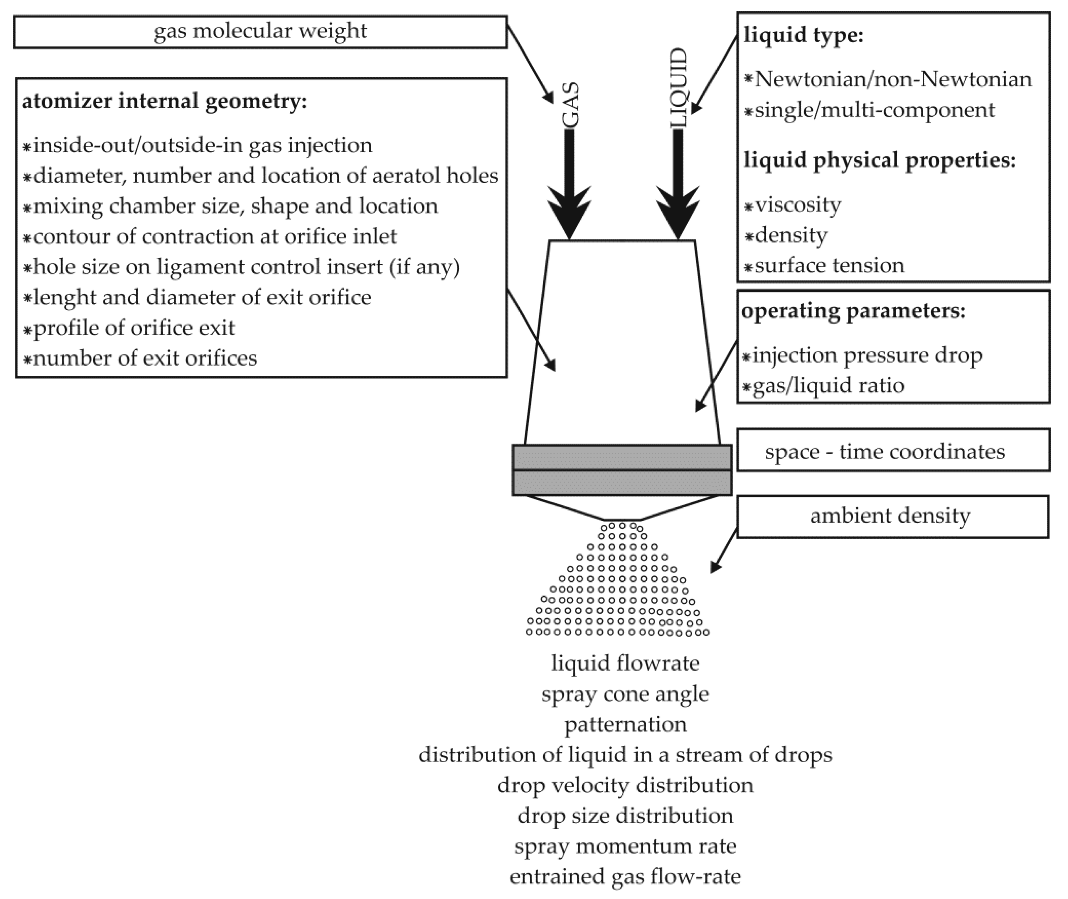
Figure 1. Graphical representation of the liquid atomization process, taking into account the influence of individual parameters [7,8].
Energies 14 02876 g001
Figure 2. Exemplary schemes of effervescent atomizers of the type [20,44]: (a) inside-out, (b) outside-in.
Energies 14 02876 g002
Figure 3. Modifications of effervescent-swirl atomizers proposed in the work [7].
Energies 14 02876 g003
Figure 4. Design of a two-phase atomizer with a swirl insert [52].
Energies 14 02876 g004
Figure 5. Schematic diagram of the two-phase atomization process in an effervescent atomizer [7,8].
Energies 14 02876 g005
Figure 6. The quality of the generated spray depends on the structure of the internal flow [84].
Energies 14 02876 g006
Figure 7. The relationship between the flow swirl insert and the diameter of the air core [85].
Energies 14 02876 g007
Figure 8. Selected structures of the sprayed liquid observed as a result of spraying water with an effervescent-swirl atomizer [7]: (a) M ˙ c = 0.0014 kg/s, C5, (b) M ˙ c = 0.021 kg/s, C5, (c) M ˙ c = 0.008 kg/s.
Energies 14 02876 g008
Figure 9. Selected structures of the sprayed liquid observed during one- and two-phase spraying of a 59% water solution of glycerin with the addition of 0.5% rocrysol WF1 with the use of an effervescent-swirl atomizer [7]: (a) M ˙ c = 0.0056 kg/s, C5, (b) M ˙ c = 0.011 kg/s, M ˙ g = 0.000028 kg/s, P, (c) M ˙ c = 0.0056 kg/s, M ˙ g = 0.000014 kg/s, LC, (d) M ˙ c = 0.028 kg/s, LC, (e) M ˙ c = 0.021 kg/s, LC.
Energies 14 02876 g009
Figure 10. Graph of the dependence of the discharge coefficient on the value of l0/d0 using effervescent and effervescent-swirl atomizers [7].
Energies 14 02876 g010
Figure 11. Summary of literature values of the discharge coefficient (d0 = 0.002 m; l0/d0 = 1; β = 0°) [7]: 1-Chen and Lefebvre [96], 2-Jedelsky and Jicha [98], 3-Ochowiak [1], 4-Ochowiak et al. [44], 5-Ramamurthi et al. [97].
Energies 14 02876 g011
Figure 12. Dependence of the liquid spray angle on GLR for liquids of different viscosity, sprayed with an effervescent-swirl atomizer [7].
Energies 14 02876 g012
Figure 13. Influence of the outlet opening diameter of the atomizer on the spray angle for inserts of various designs [54].
Energies 14 02876 g013
Figure 14. Diagram of the effervescent-swirl atomizer from the study [118,119].
Energies 14 02876 g014
Figure 15. Diagram of the dependence of spray angle on GLR determined with a classical bubble atomizer and its modifications [118].
Energies 14 02876 g015
Figure 16. Schematic diagram of the atomization process with the use of an effervescent atomizer [7,72].
Energies 14 02876 g016
Table 1. Summary of the constant c z values estimated on the basis of Equation (4) [96].
ηc [Pa · s]ρc [kg/m3]c
RSP10.0200.015
RSP20.0200.020
RSP30.0200.025
RSP40.0200.020
RSK10.0200.015
Table 2. Summary of dimensions of individual components of atomizers [118].
¦Çc [Pa · s]ρc [kg/m3]c
RSP10.0200.015
RSP20.0200.020
RSP30.0200.025
RSP40.0200.020
RSK10.0200.015
Publisher’s Note: MDPI stays neutral with regard to jurisdictional claims in published maps and institutional affiliations.