1. Introduction
The aviation industry recognizes the need to address the global challenge of climate change and has taken up a range of ambitious targets to mitigate CO
2 emissions in air transportation [
1]. High power density, reliability and integrated technologies are core pillars of the evolution of aviation. As a safety-critical subsystem, electrical power systems of more-electric aircrafts play a vital role in the continuing progression of electrification. Integrated starter–generators (SGs), which provide the functions of engine acceleration and electricity supply, are the main power source for onboard equipment.
The three-stage synchronous starter–generator is a mature candidate for current electrical power systems; it consist of a pre-exciter, a main exciter and a main generator [
2]. This architecture exhibits the remarkable benefits of reliability and inherent safety because of its de-excitation ability. In contrast, concerning the embedded power electronics on the rotating rotor, the configuration of the rotor is too complex for operation at high speed, which could result in mechanical failure. Meanwhile, different control strategies in motoring and generation modes increase the system’s complexity.
Permanent magnet starter–generators (PMSGs) for aircraft electrical power systems have been investigated [
3]. With substantial advances in power electronics and rare earth permanent magnet material, the feasibility of permanent magnet starter–generators (PMSGs) could make them a potential candidate in this safety-critical application; two cases have been investigated [
4,
5]. Both of them adopted the Halbach permanent magnet (PM) array and liquid cooling to pursue high power density design. It is worth highlighting that the specific power density of the former machine is 33 kW/L or 16 kW/kg. Similarly, a high power density PM electrical machine has been designed for flooded pump applications, with a cooling design for winding and rotor to maintain current density at 27.2 A/mm
2 [
6].
Opposition to this alternative mainly focuses on the risk of irreversible demagnetization in high temperatures due to electrical fault conditions, open circuit or short circuit (SC). Above all, “fault tolerant” (FT), which means the machine maintains operation continuously in the presence of faults, is a specific requirement for this safety-critical application.
The concept and design considerations of FT electrical machines have been summarized thoroughly [
7,
8,
9,
10,
11,
12]. The mainstream concepts in the design of an FT machine are summarized in the “redundancy” and “fault isolation” approaches. These corresponding approaches include inhibition of a short circuit current, isolation of faulty sectors and multi-phase topology. Limiting the short circuit current under a safe value by means of the high reactance design or three-phase current injection is a directly applicable and effective measure. Multi-phase topologies provide a capacity margin for post-fault operation but decrease basic reliability, which relates to the amount of electronic components.
Based on this, a number of innovative topologies have been investigated, such as modular design [
13,
14], flux controllable machine [
15,
16] and separated phase machine [
17]. The modular design derives from multiphase machines. The objective of partitioning is easy to meet, except concerning short-circuit current suppression. Nevertheless, for modular design, a trade-off of system reliability and complexity is necessary. The flux-controllable design has intrinsic fault tolerance due to its double-salient structure as a switch reluctance motor; it is easily demagnetized in the presence of a fault. Meanwhile, the complicated topology, manufacturing and assembly issues are visible demerits. The separated phase design exhibits thorough isolation in the presence of a fault. However, the potential mechanical issues, stiffness and strength of the rotor cannot be neglected in high-speed operation, especially in post-fault operation. These novel topologies could pave the way for FT PM machines on starter–generators.
The main objective of this paper is to present a design and trade-off process for a surface mounted PMSG to meet the requirements of high power density and fault tolerance. Based on the techniques and trends of modern electrical machine design optimization review [
18], the multiple objective optimization electromagnetic design method was adopted, with a range of slot/pole combination machines for performance ranking and selection. Aimed at an FT design, the multiple three-phase winding topology and FT performance were investigated.
The application requirements, limitation and the initial design are presented in
Section 2. In
Section 3, the selection of degrees of freedom, the multiple objective optimization design and the ranking process are presented as benchmarks. To investigate the feasibility of winding for FT designs, comprehensive multiple three-phase and FT performance comparisons were carried out, as described in
Section 4. Following the selection, the final model, considered electromagnetic and FT, was validated by finite element analysis, as addressed in conclusive remarks in
Section 5.
2. Design Requirements and Initial Definition
Starter–generators could provide a continuous speed range for engines from standstill to ignition speed and maximum speed, these two states being divided into the motoring mode and the generation mode, respectively. In the motoring mode, the SG could provide output to overcome resistive torque from propellers, gear boxes and accessories. After successful engine ignition, the SG generates electricity for the whole system. The torque-speed characteristics of the PMSG are shown in
Figure 1.
Besides the requirements of energy conversion, the specific PMSG should satisfy the requirements of geometrical and environment limitations aimed to be embedded in propeller housing. The specification of the PMSG has been illustrated in
Table 1.
The DC-link voltage of the power converter is set at 540 V. These two important operating points, base speed at 12,000 rpm and max speed at 18,000 rpm should provide the output power 50 kW. The geometrical envelope is limited to 170 mm × 95 mm ×120 mm (outer diameter × inner diameter × length) because of engine housing and hallow shaft space. The interface of oil cooling is provided by the aeroengine, which allows the adoption of high power loading and achievement of a higher power density.
The final design should take full advantage of the radial direction to arrange electrical components, stator, stator sleeve, airgap and rotor assembly (surface mounted or interior PM). In the selection of rotor type, an interior PM machine is not feasible for this specific application due to the rotor being thicker than the surface PM-type; the Halbach PM array is adopted to pursue a thin rotor assembly.
Moreover, considering the high temperature risk for the operation environment and the need to avoid the risk of demagnetization, samarium cobalt (SmCo), Recoma 33E (supplier: Arnold Magnetic Technologies, Sheffield, UK), which has a maximum operating temperature of 350 °C, could be an effective PM candidate instead of neodymium–iron–boron permanent magnets (NdFeB). To decrease the eddy current losses, PM segmentation in the machine’s axial direction was adopted.
Sleeves are necessary for the stator and rotor, for maintaining coolant in the cooling zone and protecting PM retention in a high-speed rotating rotor, respectively. The carbon fiber sleeve exhibits higher specific strength and no eddy current loss than metal sleeves.
With regard to the need for reliability concerning the safety-critical application, the machine should maintain operation continuously in the presence of electrical faults, short circuit or open circuit. In other words, FT is another key design objective of this specific application.
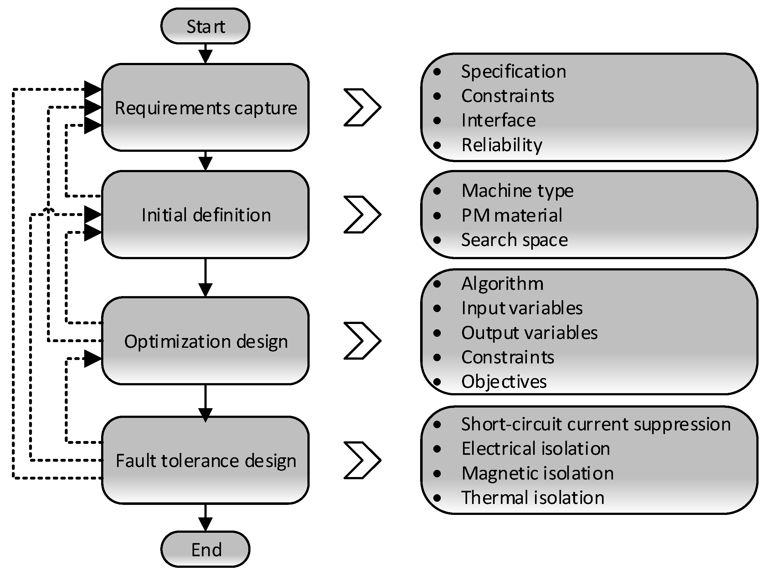
The iterative machine design processes of the main phases and corresponding tasks are shown in
Figure 2; dashed lines mean the loops for potential iteration(s). The design process is derived from model-based systems engineering (MBSE), which is a system engineering methodology that focuses on creating and exploiting domain models as the primary means of information.
In the first stage, requirements capture, requirements elicitation and analysis involve first collecting as many potential requirements as possible, then refining them to form a complete, concise and consistent set of functional and non-functional requirements.
Concerning the initial definitions, it can be seen from the foregoing that requirements capture is a priority activity in verifying and quantifying all the necessary information that contributes to a complete and coherent machine design.
As mentioned, high power density is one of the key design targets; the following design involves a trade-off between power density and fault tolerance.
3. Optimization Design
Based on the initial definitions of machine type, PM material and cooling method, the following machine optimization design process should begin with the selection of a slot (Q)/pole (p) combination with corresponding winding arrangement, distributed winding (DW) or concentrated winding (CW). Subsequently, the multiple objective optimization model could be created with definitions and settings of variables, genetic algorithm, objectives and constraints. Afterwards, the multiple criterion decision maker (MCDM) method could be adopted to rank the single and comprehensive performance of different slot/pole combinations.
3.1. Selection of Slot/Pole Combination
In addition to meeting the requirements of the winding theory, the number of slots, Q, should be set as a multiple of six to ensure better performance concerning the unbalanced axial force. The upper limit of the outer diameter of the motor is fixed, which determines the maximum number of slots—less than 48 because of manufacturing difficulties and teeth strength.
Generally, a higher pole number,
p, leads to bigger switching losses in power electronics and also higher frequency operation. Therefore, the potential slot/pole combinations of the machine were calculated according to the methods laid out in [
19], and are listed in
Table 2, in which the 15 slot/pole candidates that could be selected for the following design because of their higher winding factor are highlighted (red color).
The machine will be integrated into an aeroengine; the space of the engine shaft should be φ95 mm. To improve the airgap flux density while considering the limitation of the thin rotor back-iron, a Halbach array PM arrangement was selected.
3.2. Multiple Objective Design
To pursue a high power density design, the slot coolant jacket cooling method was adopted for every combination; fluid passed axially down the machine through the slot. The key benefit of this type of cooling is the close proximity of the fluid to the conductors, resulting in a short thermal path and effective heat removal directly from the source. The area for the cooling duct competes with the area for the conductors, so there is typically a compromise between copper loss and cooling. A continuous high current density could be maintained, at about 20 A/mm2.
The approach of multiple objective optimization is an effective tool to get a balanced design. The typical optimization consists of objectives, constraints, variable space and algorithm. The computational efficiency and accuracy results of the iterative process depend on elements that could be divided into the following tasks. Adopting this method for every candidate is a fair way to rank their performance at rated operation points (base speed).
3.2.1. Objectives and Constraints
In order to efficiently obtain reliable results in the space, the top priority is correctly defining the objectives and constraints. As previously mentioned, high power density is a key target. In other words, under the premise of ensuring the rated power output, the machine weight of active parts, which includes lamination of stator, rotor, PMs, windings and shaft, W, should be optimized to be as light as possible. Likewise, higher efficiency, η, means less energy loss.
Subsequently, effective fault tolerance is another core objective for this PMSG. In this case, suppression of the stable peak value of SC,
ISC, is the best way to cope with the most fatal fault in the electrical machine side [
20]. This goal could be achieved by means of a high reactance design [
21]. In the 2D model, the narrow and deep slot type has higher slot leakage reactance, which restrains the SC current. The search space consists of the dimensional variable in the stator (including the slot), PMs and rotor iron. To summarize, the analysis process could iterate along these directions:
W, weight of active parts (minimize).
η, efficiency (maximize).
ISC, SC current (minimize).
The definitions of constraints are more quantitative than those of objectives, by assigning specific thresholds:
The power density, kW/kg, could be defined by the ratio of output power to weight of active parts. All the 15 combinations have the same settings for current density, 20 A/mm2, realizable with the cooling method.
3.2.2. Search Space
The surface mounted Halbach array of permanent magnet topology was chosen for the foregoing section as the fundamental topology [
22]. Meanwhile, 2 mm carbon fiber bonding was designed to bond the Halbach array PMs on the rotor for every combination. Filament-wound composite sleeves of permanent magnet motor rotors offer a superior design alternative for higher performance applications at high speed. Besides, carbon fiber encapsulation is a perfect fit for systems that must operate reliably in extreme conditions while reducing system weight.
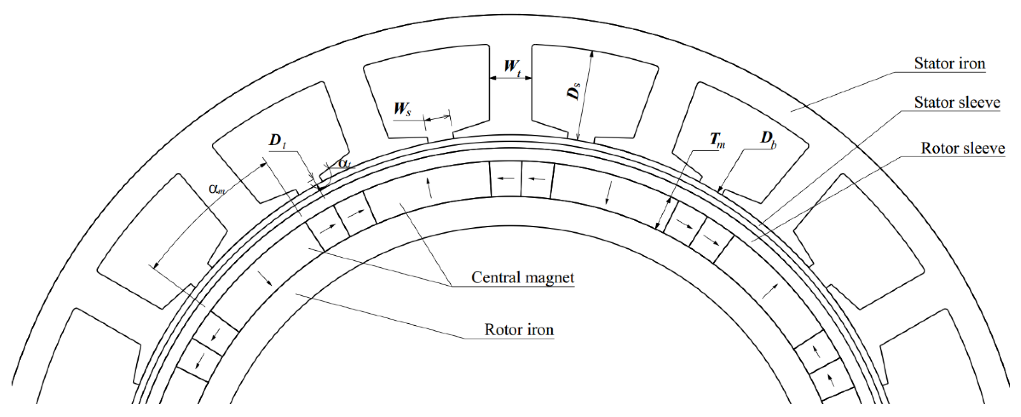
To balance the manufacturing difficulties and advantages of the Halbach array, every pole could be divided into three parts with different magnetization direction (showed in
Figure 3); the central magnet aligns with the radial direction and the other two parts are perpendicular to the central magnet, pointing in an opposite direction. The central arc of the magnet could be a variable for this optimization and selection.
Besides some fixed parameters, a set of variables were selected that closely affect the performance of the motor, such as diameter of stator bore
Db, width of tooth
Wt, depth of slot
Ds, opening of slot
Ws, depth of tooth tip
Dt, angle of tooth tip
αt, thickness of magnet
Tm and angle of central magnet
αm, as shown in
Figure 3. It is worth mentioning that the scope of the same variable in different slot/pole combinations is varied. The range of the variable should be distributed reasonably to avoid geometrical conflict.
3.2.3. Exploration of the Solution Space
The number of optimization designs is determined by the design of experiments (DoE) and evolutionary algorithm.
The nondominated sorting genetic algorithm (NSGA-II) is adopted for the optimization work. The number of designs is determined by the number of generations and size of initial group, which should involve a compromise between reliable results and runtime. The number of designs is 20 and the number of generators is 40 in every slot/pole optimization. Due to the reasonable definitions of variables range, for every slot/pole combination, 800 designs are feasible for search space to obtain proper candidate design. The computation time for every design is about 60 s, and the total time consumption is acceptable.
3.2.4. Evaluation and Comparison
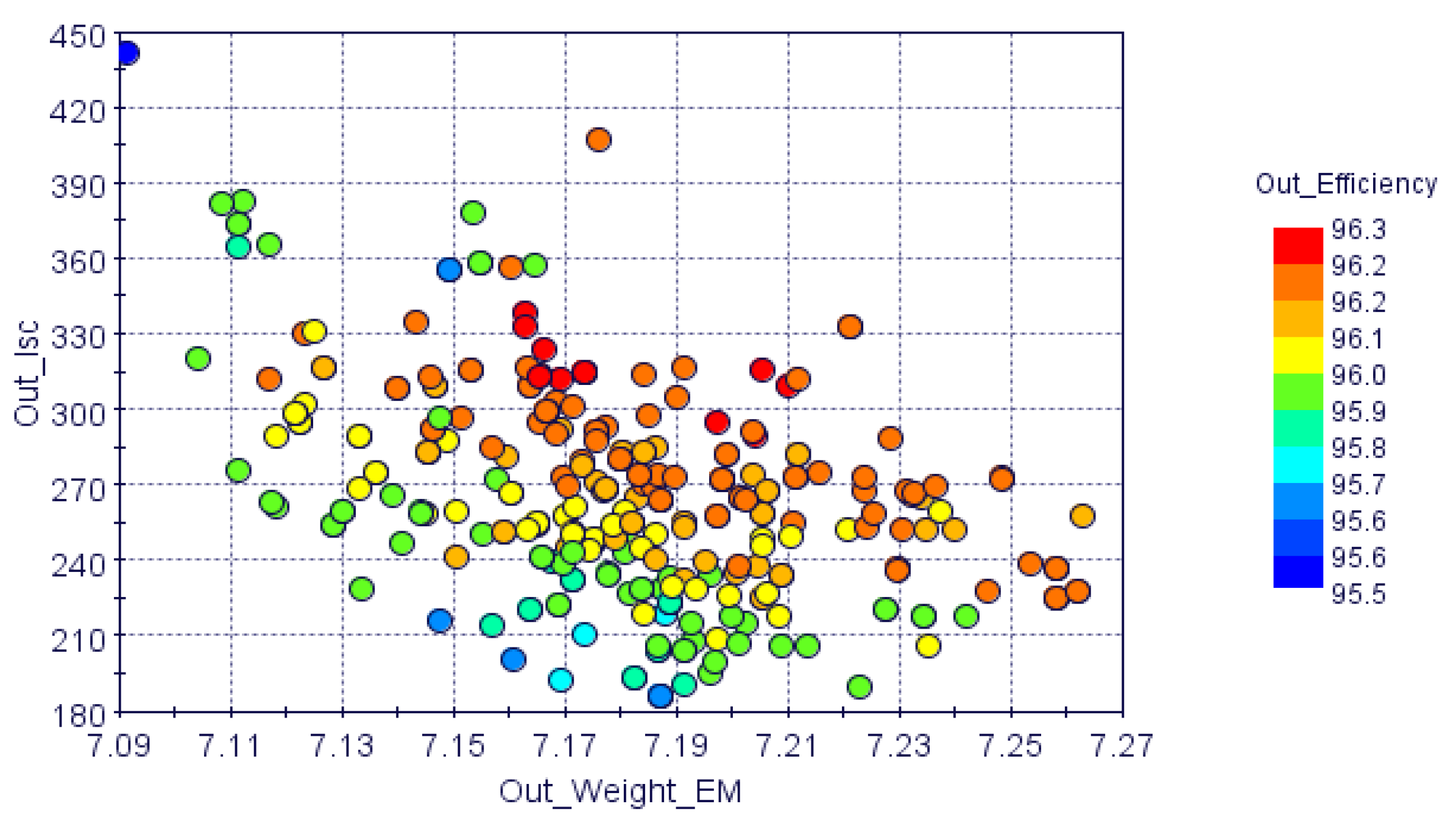
After the optimization analysis based on the joint simulation, optimization software modeFRONTIER and finite element analysis software Motor-CAD, all the feasible designs could be filtered out by constraints. The method of Pareto front is a common and intuitive approach for an optimization problem with two objectives but is inapplicable for a scenario that requires three objectives.
Figure 4 shows a bubble chart that exhibits a visualization of the values of weight (kg) and the short circuit current (A) plane with the efficiency (%) values being shown as colored bubbles. All the points meet the requirements. It is difficult to choose the best design from the colorful chart.
By assigning weighting factors, the multiple objective optimization results could be transformed to single objective optimization, which is easy to compare and rank. In this case, the three objectives are assigned equal weighting factors, 1/3, considering the requirements for high power density and fault tolerance.
Table 3 illustrates the comprehensive rank of potential slot/pole combinations based on
η,
ISC and
W, excluding five unfeasible combinations. It is worth knowing that the order may be varied in terms of weighting factor assignment. In the results, 18/12, 36/12 and 42/10 are the top three candidates in sequence for the specific PMSG.
Meanwhile, to review the detailed performance, the 18 slot/12 pole combination could provide 56.0 kW output power at base speed, with the weight of electromagnetic components being 7.12 kg. The power density of this combination is about 7.9 kW/kg.
4. Fault Tolerance Design
Besides the direct approach to inhibit the SC current for the sake of an FT design, fault isolation is another design philosophy that isolates the fault part from the entire machine. There are three fundamental and correlated aspects: Electrical, magnetic and thermal isolation.
4.1. Electrical Isolation
The most direct means of electrical isolation is the use of every single-phase drive with H-bridge to ensure an independent power supply [
7]. While power electronics involves high costs and high power ratings, the multiple three-phase method is a compromise approach with benefits in cost, redundancy and post-fault performance.
The feasibility of multiple three-phase winding for these 13 combinations with different winding arrangements, double layer (DL) or single layer (SL), were investigated for dual, triple, quadruple and sextuple three-phases in sequence, see
Table 4. These conclusions are the result of qualitative analysis based on winding theory [
19]. In general, SL winding could exhibit better fault tolerance than DL winding, due to its higher inductance, lower short circuit current and coupling. The ticks (‘√’) and crosses (‘×’) represent whether a topology is feasible or not, respectively. Every combination with double-layer winding could be transformed into a dual three-phase by dividing the winding symmetrically.
Multiple three-phase topologies provide a high-level margin for mission reliability but reduce the basic reliability, which relates to the number of electronic components. Dual three-phase winding topologies are selected because of their balance between FT redundancy and cost.
4.2. Magnetic Isolation
The main purpose of magnetic isolation is to pursue low mutual inductance between faulty and healthy windings [
23,
24]. In the presence of fault operation, fault winding could put the healthy winding at risk by induced voltage derived from the fault current. The configuration of windings includes concentrated and distributed ones, such as 18 slot/12 pole (or 12 slot/10 pole) and 36 slot/12 pole, respectively. The most intuitive difference between two kinds of winding is whether the windings overlap, as shown in
Figure 5.
To compare the magnet coupling between the two sets of three-phase windings (
ABC and
A′B′C′), there is a quantitative ratio that is determined by maximum mutual inductance (in the top right) over minimum self-inductance (in the diagonal of matrix) in the dual three-phase inductance matrix.
4.3. Thermal Isolation
If coils were to overheat because of a short circuit current, it would speed up the ageing of the insulating material and shorten the life of the motor. The lifetime of insulation is temperature dependent, and the capacity to insulate well sharply decreases if operated sufficiently beyond the rated value [
25].
Besides the benefits of the cooling method, a similar solution to the magnetic isolation, non-overlapped and non-contact winding arrangement could be the isolation of the thermal conduction between the fault and the healthy winding. In particular, a single-layer fractional slot concentrated winding machine meets the target. Meanwhile, it is safe to choose the copper wire and permanent magnet with high temperature resistance as far as possible to cope with FT operations.
Above all, the comprehensive evaluations of fault tolerance in these 13 combinations that have met the specifications have been investigated in the three aspects, electrical (E)/magnetic (M)/thermal (T) isolation, see
Table 5. These conclusions are the results of qualitative analysis based on definitions given in
Section 4. Like distributed windings, overlapped windings easily conduct heat, which is obviously harmful for thermal isolation in the presence of faults.
Ticks (‘√’) and crosses (‘×’) represent whether this topology is feasible or not and plusses (‘+’) and minuses (‘−’) correspond to the performance of the FT design. In conclusion, a dual three-phase 18 slot/12 pole with double-layer winding arrangement topology is optimal for the specific application.
5. Finite Element Analysis (FEA) Verification
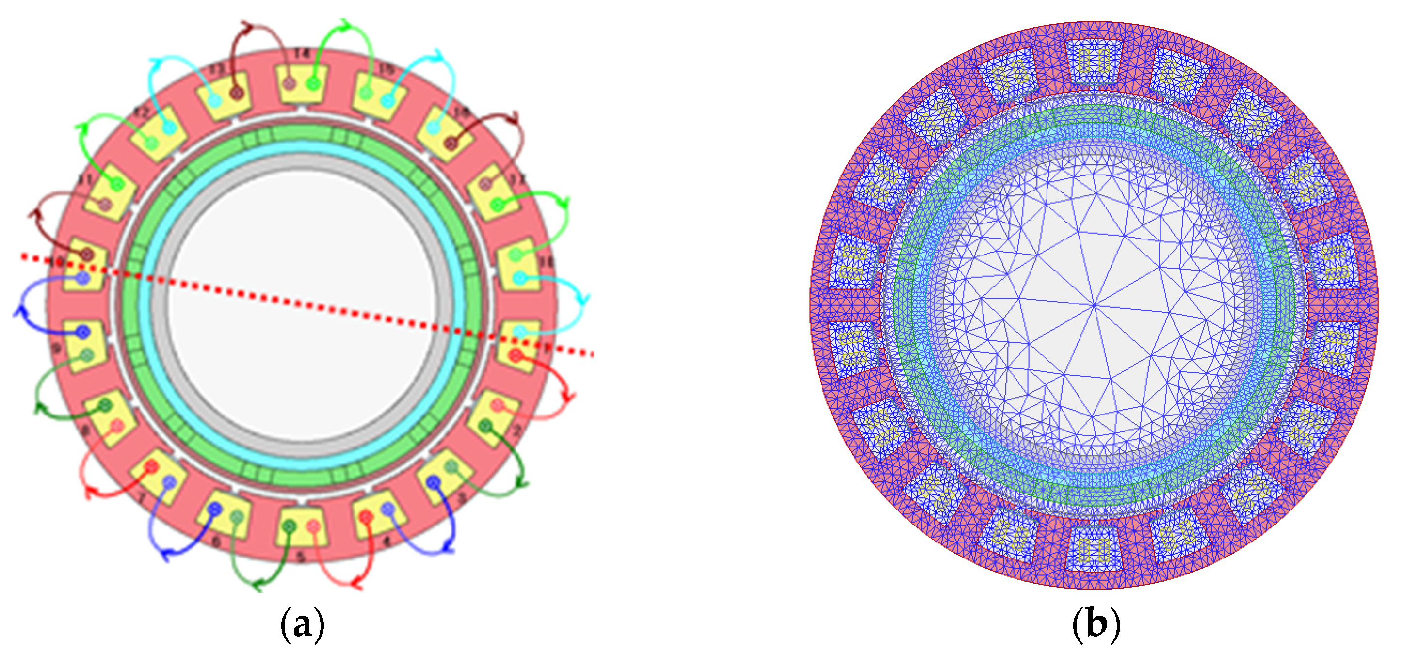
The optimal model of dual three-phase 18 slot/12 pole permanent magnet starter–generators was created using the electromagnetic simulation software ANSYS Maxwell, see
Figure 6, which presents the finite element topology model and meshing plots. In this simulation, the material of PM and lamination are Recoma 33E and N10 0.1 strip, respectively. The whole machine was built to analyze the post-fault performance and to determine which three-phase may be faulty.
5.1. Normal Opeartion
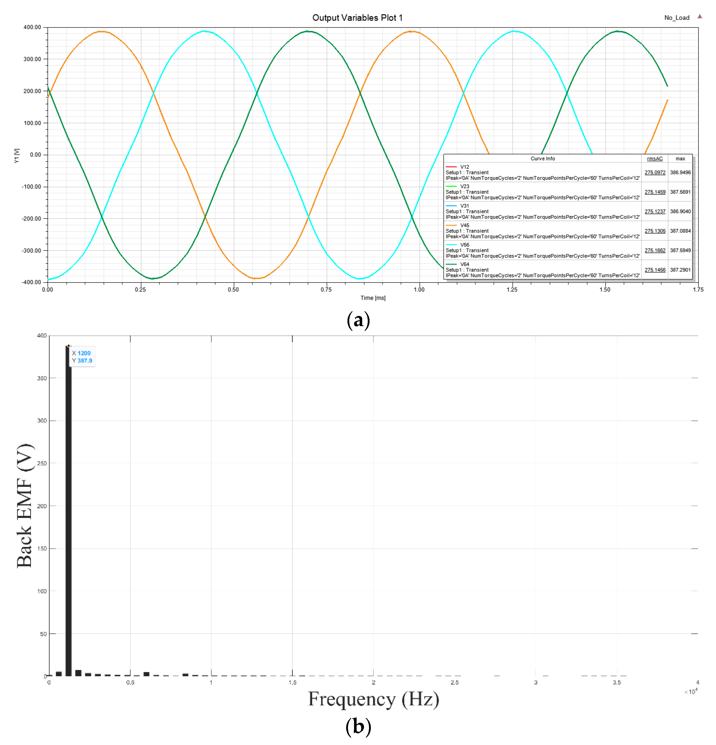
The normal operation mode was simulated. The waveforms of back electromotive force (EMF) and its fast Fourier transform (FFT) are shown in
Figure 7a,b. Based on the FFT results, the waveform of back EMF is fine sinusoidal because of its low harmonic components.
The performance and power loss distribution in different components areexhibited in
Table 6 and
Table 7 for the base speed operation point, 12,000 rpm. Moreover, in
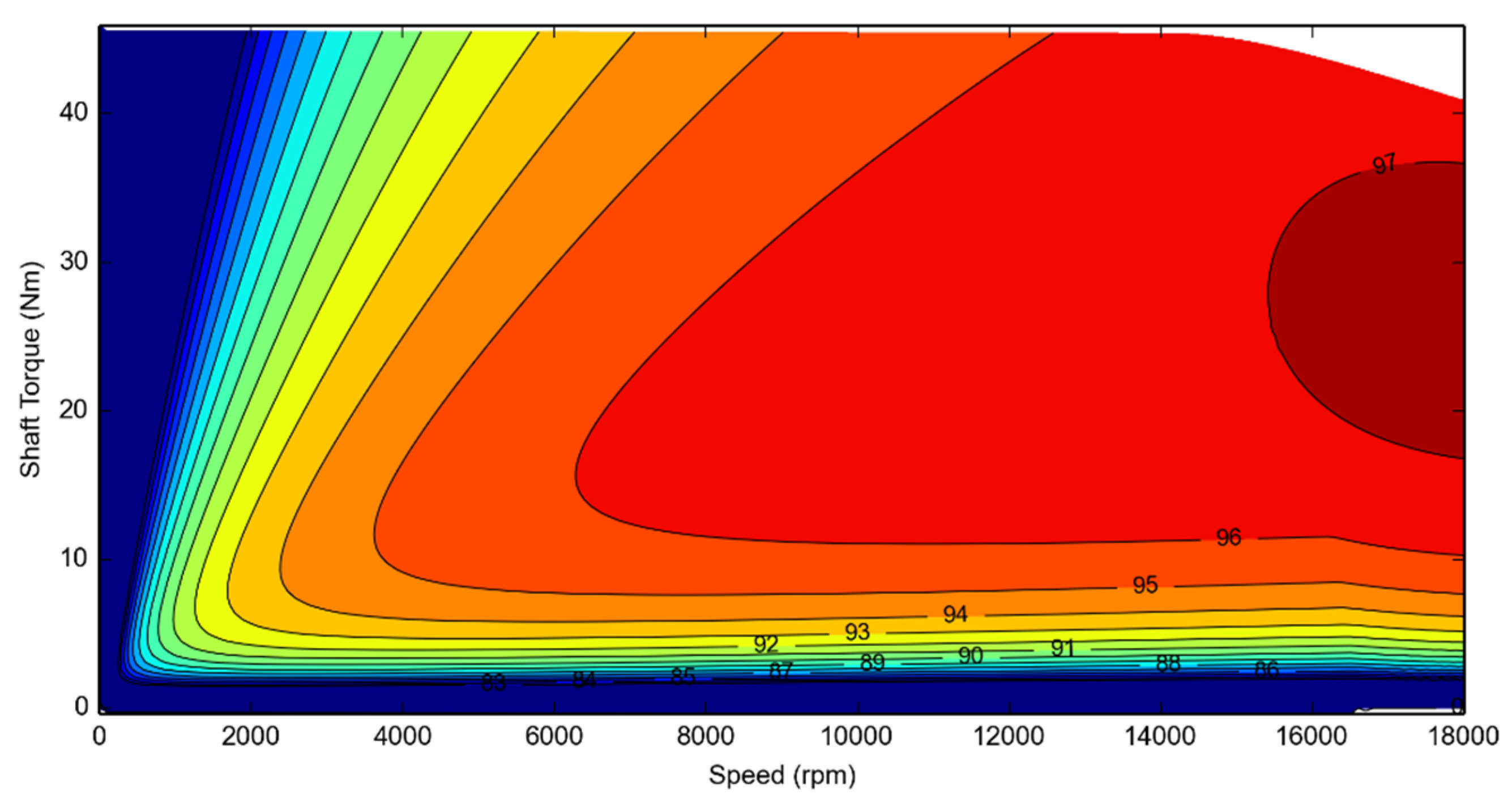
Figure 8 the efficiency map from standstill to maximum speed is exhibited and clearly shows the visualization of values of torque-speed with the efficiency values.
The key operation point, base speed and max speed, could maintain high efficiency (>95%) output. Moreover, the machine has a power margin prepared in consideration of a possible downgraded operation, due to faults.
5.2. Post-Fault Opeartion
For the sake of reliability in the safety-critical application, this machine has been designed to maintain operation continuously in fault scenarios, open circuit and short circuit. In order to verify the fault tolerance, the post-fault behavior was investigated. The dual three-phase machine is independent concerning the external electrical circuit as two sets. A fault was assumed in one set of three-phases and the other set of three-phases was kept healthy.
5.2.1. Open Circuit Operation
The open circuit occurred in one set of three-phases. There is no current in the open circuit and therefore no energy conversion in it. The machine decreases on a similar scale to the output power, according to the number of open circuits. The degradation of performance is also predictable.
Compared with normal operation, the case of three-phase open circuit was examined and compared, see
Table 8. Due to the absence of one three-phase, output torque was reduced by half. Torque ripple shows a slight increment. Unbalanced radial force spikes dramatically due to the winding arrangement—two sets of windings mounted in semi stator, separately.
5.2.2. Short Circuit Operation
In this case, the healthy three-phase maintains the output while a short circuit occurred in the faulty set.
The behavior and effect of the short circuit is more complicated than the open circuit because of the existence of an SC current in continuous operation. The drag torque generated by the SC current could reduce the output of the machine. A three-phase symmetrical SC fault is most likely to be caused by a failure in the power electronics and the effect of drag torque in this scenario is bigger. Therefore, SC of one three-phase symmetrical is studied in this section.
After a short duration, the SC winding will operate at a stable status. The SC operation causes a conspicuous shock for the machine; the torque ripple and unbalanced axial force rises more rapidly with the half torque loss than in normal circumstances, see
Table 8.
It is worth mentioning the unbalanced radial force in the faulty scenarios. In the open circuit, the unbalanced radial force could increase dramatically due to the absence of phases and will persist. In the short circuit, it is totally different to the open circuit, because the current still exists in the fault windings. The peak value of unbalanced force is attenuated from peak value to a lower value, which depends on the fault tolerance. In this case, the unbalance axial force in the short circuit reduces back to a much lower value. By selecting proper bearing pairs, the effect derived from the above-mentioned force will be tolerated.
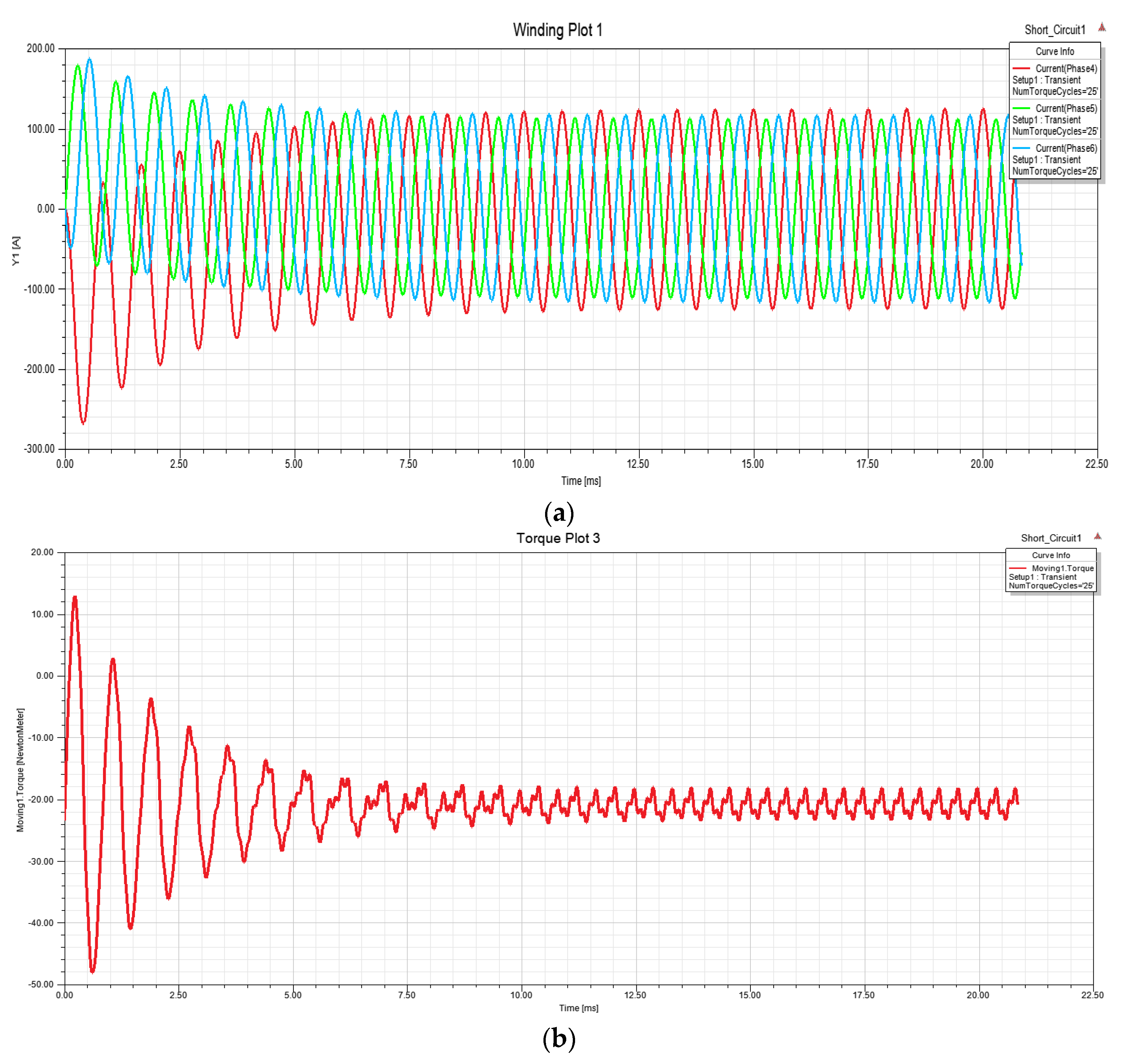
The SC behavior is exhibited in
Figure 9. A steady state (from 7.5 ms) current is limited by the phase inductance and the incomplete machine could operate continuously under the thermal limit, which meets the requirement of being fail-safe. The rated peak value of the phase current is 88.4 A. After a short duration, SC returns to the sinusoidal waveform, and the stable peak current is 122.5 A, which is considered as the reference for wires, power electronics and cooling method, as shown in
Figure 9a. The transient drag torque causes conspicuous torque ripple, which is flattened in a stable status, see
Figure 9b.
As considered in the optimization and FT design process, the FEA results of normal and post-fault performances verify the design objectives.
6. Conclusions
In this paper, a permanent magnet starter–generator was designed addressing the core challenges: High power density and fault tolerance.
Under the specific application, the 18 slot/12 pole surface mounted PM machine shows a better comprehensive performance than other topologies under the restrictions of specification and space envelope. The design process is demonstrated by the method of multiple objective optimization, with light weight, high efficiency and low SC current. The optimized 18 slot/12 pole PMSG exhibits high power density, at about 7.9 kW/kg.
To pave the way for operation in fault scenarios, fault partitions were designed for electrical, magnetic and thermal isolation. Based on the electromagnetic performance rank, the feasibility of multiple three-phases for all candidates has been illustrated. Based on the compromise between redundancy and complexity, a dual three-phase 18 slot/12 pole double-layer concentrated winding was selected as the candidate for this application.
The results of FEA analysis give evidence of suitable performance in normal and post-fault circumstances. With the benefits of FT, the machine could maintain operation continuously. In the worst conditions, the short-circuit current is limited to an acceptable level.
Author Contributions
Conceptualization, B.W. and Y.L.; methodology, G.V.; software, B.W.; validation, B.W. and Y.L.; formal analysis, B.W.; investigation, B.W.; resources, T.Y.; data curation, B.W.; writing—original draft preparation, B.W.; writing—review and editing, G.V., Z.Z.; visualization, Y.L.; supervision, G.V.; T.Y., C.G.; project administration, T.Y.; funding acquisition, T.Y. All authors have read and agreed to the published version of the manuscript.
Funding
This project has received funding from the Clean Sky 2 Joint Undertaking under the European Union’s Horizon 2020 research and innovation programme under grant agreement No 737814.
Institutional Review Board Statement
Not applicable.
Informed Consent Statement
Not applicable.
Data Availability Statement
Data available in a publicly accessible repository.
Acknowledgments
Bo Wang is supported by the China Scholarship Council (201805270050).
Conflicts of Interest
The authors declare no conflict of interest.
References
- ITAT. Aircraft Technology Roadmap to 2050. 2019. Available online: https://www.iata.org/en/publications/technology-roadmap/ (accessed on 1 August 2019).
- Moir, I.; Seabridge, A. Aircraft Systems: Mechanical, Electrical, and Avionics Subsystems Integration; John Wiley & Sons: Hoboken, NJ, USA, 2011. [Google Scholar]
- Zhang, Z.; Huang, J.; Jiang, Y.; Geng, W.; Xu, Y. Overview and analysis of PM starter/generator for aircraft electrical power systems. CES Trans. Electr. Mach. Syst. 2017, 1, 117–131. [Google Scholar] [CrossRef]
- Bozhko, S.; Yang, T. Development of Aircraft Electric Starter–Generator System Based on Active Rectification Technology. IEEE Trans. Transp. Electrif. 2018, 4, 985–996. [Google Scholar] [CrossRef]
- Khowja, M.R.; Vakil, G.; Gerada, C.; Yang, T.; Bozhko, S.; Wheeler, P. Trade-off Study of a High Power Density Starter-Generator for Turboprop Aircraft System. In Proceedings of the IECON 2019-45th Annual Conference of the IEEE Industrial Electronics Society, Lisbon, Portugal, 14–17 October 2019; Volume 1, pp. 1435–1440. [Google Scholar]
- Al-Timimy, A.; Giangrande, P.; Degano, M.; Xu, Z.; Galea, M.; Gerada, C.; Calzo, G.L.; Zhang, H.; Xia, L. Design and losses analysis of a high power density machine for flooded pump applications. IEEE Trans. Ind. Appl. 2018, 54, 3260–3270. [Google Scholar] [CrossRef]
- Bennett, J.W.; Atkinson, G.J.; Mecrow, B.C.; Atkinson, D.J. Fault-tolerant design considerations and control strategies for aerospace drives. IEEE Trans. Ind. Electron. 2011, 59, 2049–2058. [Google Scholar] [CrossRef]
- Wolmarans, J.; Polinder, H.; Ferreira, J.; Clarenbach, D. Selecting an optimum number of system phases for an integrated, fault tolerant permanent magnet machine and drive. In Proceedings of the 2009 13th European Conference on Power Electronics and Applications, Barcelona, Spain, 8–10 September 2009; pp. 1–10. [Google Scholar]
- Cao, W.; Mecrow, B.C.; Atkinson, G.J.; Bennett, J.W.; Atkinson, D.J. Overview of electric motor technologies used for more electric aircraft (MEA). IEEE Trans. Ind. Electron. 2011, 59, 3523–3531. [Google Scholar]
- Arumugam, P.; Hamiti, T.; Brunson, C.; Gerada, C. Analysis of vertical strip wound fault-tolerant permanent magnet synchronous machines. IEEE Trans. Ind. Electron. 2013, 61, 1158–1168. [Google Scholar] [CrossRef]
- Dusek, J.; Arumugam, P.; Brunson, C.; Amankwah, E.K.; Hamiti, T.; Gerada, C. Impact of slot/pole combination on inter-turn short-circuit current in fault-tolerant permanent magnet machines. IEEE Trans. Magn. 2015, 52, 1–9. [Google Scholar] [CrossRef]
- Zhang, Y.X.W.; Huang, Y.; Zou, J. Reduction of High-frequency Vibration Noise for Dual-branch Three-phase Permanent Magnet Synchronous Motors. Chin. J. Electr. Eng. 2020, 6, 42–51. [Google Scholar] [CrossRef]
- Arumugam, P.; Xu, Z.; La Rocca, A.; Vakil, G.; Dickinson, M.; Amankwah, E.; Hamiti, T.; Bozhko, S.; Gerada, C.; Pickering, S.J. High-speed solid rotor permanent magnet machines: Concept and design. IEEE Trans. Transp. Electrif. 2016, 2, 391–400. [Google Scholar] [CrossRef]
- Ifedi, C.J.; Mecrow, B.C.; Brockway, S.T.; Boast, G.S.; Atkinson, G.J.; Kostic-Perovic, D. Fault-tolerant in-wheel motor topologies for high-performance electric vehicles. IEEE Trans. Ind. Appl. 2013, 49, 1249–1257. [Google Scholar] [CrossRef]
- Raminosoa, T.; Gerada, C.; Galea, M. Design considerations for a fault-tolerant flux-switching permanent-magnet machine. IEEE Trans. Ind. Electron. 2010, 58, 2818–2825. [Google Scholar] [CrossRef]
- Zhang, Z.; Liu, Y.; Li, J. A HESM-based variable frequency AC starter-generator system for aircraft applications. IEEE Trans. Energy Convers. 2018, 33, 1998–2006. [Google Scholar] [CrossRef]
- Chai, F.; Geng, L.; Pei, Y. A Novel Fault Tolerant Machine With Integral Slot Non-Overlapping Concentrated Winding. IEEE Access 2019, 7, 99462–99469. [Google Scholar] [CrossRef]
- Bramerdorfer, G.; Tapia, J.A.; Pyrhönen, J.J.; Cavagnino, A. Modern electrical machine design optimization: Techniques, trends, and best practices. IEEE Trans. Ind. Electron. 2018, 65, 7672–7684. [Google Scholar] [CrossRef]
- Krishnan, R. Permanent Magnet Synchronous and Brushless DC Motor Drives; CRC Press: Boca Raton, FL, USA, 2017. [Google Scholar]
- Bonnett, A.H.; Yung, C. Increased efficiency versus increased reliability. IEEE Ind. Appl. Mag. 2008, 14, 29–36. [Google Scholar] [CrossRef]
- Jiang, X.; Wang, S.; Li, Q.; Gao, Y. Design and optimization of dual-winding fault-tolerant permanent magnet motor. CES Trans. Electr. Mach. Syst. 2019, 3, 45–53. [Google Scholar] [CrossRef]
- Zhu, Z. Recent development of Halbach permanent magnet machines and applications. In Proceedings of the 2007 Power Conversion Conference-Nagoya, Nagoya, Japan, 2–5 April 2007; pp. K-9–K-16. [Google Scholar]
- Ishak, D.; Zhu, Z.; Howe, D. Comparison of PM brushless motors, having either all teeth or alternate teeth wound. IEEE Trans. Energy Convers. 2006, 21, 95–103. [Google Scholar] [CrossRef]
- Barcaro, M.; Bianchi, N.; Magnussen, F. Analysis and tests of a dual three-phase 12-slot 10-pole permanent-magnet motor. IEEE Trans. Ind. Appl. 2010, 46, 2355–2362. [Google Scholar] [CrossRef]
- Bryan, J. Service Factor: What Is It and What Does It Do? Electric Apparatus Service Association: St. Louis, MO, USA, 2015. [Google Scholar]
Figure 1.
Schematic of torque-speed characteristics.
Figure 1.
Schematic of torque-speed characteristics.
Figure 2.
Design process of main phases and tasks.
Figure 2.
Design process of main phases and tasks.
Figure 3.
Schematic of the rotor assembly.
Figure 3.
Schematic of the rotor assembly.
Figure 4.
Visualization results of a feasible design in the 18 slot/12 pole combination.
Figure 4.
Visualization results of a feasible design in the 18 slot/12 pole combination.
Figure 5.
Winding arrangement and phasor diagram of dual three-phase in (a) 18 slot/12 pole, double layer (DL); (b) 36 slot/12 pole, DL; (c) 36 slot/12 pole, single layer (SL); (d) 12 slot/10 pole SL.
Figure 5.
Winding arrangement and phasor diagram of dual three-phase in (a) 18 slot/12 pole, double layer (DL); (b) 36 slot/12 pole, DL; (c) 36 slot/12 pole, single layer (SL); (d) 12 slot/10 pole SL.
Figure 6.
Dual three-phase, concentrated winding, 18 slot/12 pole in ANSYS Maxwell: (a) Topology model; (b) meshing plots.
Figure 6.
Dual three-phase, concentrated winding, 18 slot/12 pole in ANSYS Maxwell: (a) Topology model; (b) meshing plots.
Figure 7.
The waveform of (a) no-load line-line back EMF, (b) analysis of harmonics.
Figure 7.
The waveform of (a) no-load line-line back EMF, (b) analysis of harmonics.
Figure 8.
Efficiency map of the whole speed range.
Figure 8.
Efficiency map of the whole speed range.
Figure 9.
Short circuit behavior: (a) SC current in the fault phases; (b) output torque.
Figure 9.
Short circuit behavior: (a) SC current in the fault phases; (b) output torque.
Table 1.
The specifications of the permanent magnet starter–generator (PMSG).
Table 1.
The specifications of the permanent magnet starter–generator (PMSG).
| Parameters | Value | Unit |
|---|
| DC-link Voltage | 540 | V |
| Base speed | 12,000 | rpm |
| Maximum speed | 18,000 | rpm |
| Output Power @ 12,000 rpm | 50 | kW |
| Output Power at 18,000 rpm | 50 | kW |
| Out diameter | 170 | mm |
| Inner diameter | 95 | mm |
| Coolant | Oil | - |
| Fluid volume flow rate | 6 | Lt/min |
| Coolant temperature | 50 | Celsius |
Table 2.
The winding factor of varied slot/pole combinations.
Table 2.
The winding factor of varied slot/pole combinations.
| Q/p | 6 | 8 | 10 | 12 |
|---|
| 6 | - | 0.866 | 0.866 | - |
| 12 | - | 0.866 | 0.933 | - |
| 18 | 1 | 0.945 | 0.735 | 0.866 |
| 24 | - | 1 | 0.925 | - |
| 30 | - | 0.909 | 1 | - |
| 36 | 0.966 | 0.945 | 0.923 | 1 |
| 42 | - | 0.953 | 0.953 | - |
| 48 | - | 0.966 | 0.923 | - |
Table 3.
The comprehensive rank of feasible combination.
Table 3.
The comprehensive rank of feasible combination.
| Rank1 | Case | η (%) | ISC (A) | W (kg) | Ranking Value |
|---|
| 1 | 18/12 | 95.45 | 253.47 | 7.12 | 0.81 |
| 2 | 36/12 | 95.77 | 349.16 | 7.22 | 0.81 |
| 3 | 42/10 | 95.66 | 503.76 | 7.08 | 0.73 |
| 4 | 24/10 | 95.52 | 456.66 | 7.06 | 0.73 |
| 5 | 12/10 | 95.58 | 268.00 | 7.38 | 0.68 |
| 6 | 30/10 | 95.74 | 426.98 | 7.34 | 0.65 |
| 7 | 36/10 | 95.39 | 461.93 | 7.17 | 0.58 |
| 8 | 48/10 | 95.79 | 677.24 | 7.18 | 0.58 |
| 9 | 36/8 | 95.02 | 408.31 | 7.29 | 0.38 |
| 10 | 42/8 | 95.35 | 512.58 | 7.42 | 0.36 |
| 11 | 24/8 | 95.33 | 462.54 | 7.49 | 0.34 |
| 12 | 18/8 | 95.12 | 337.47 | 7.54 | 0.31 |
| 13 | 48/8 | 95.25 | 575.66 | 7.45 | 0.25 |
Table 4.
The feasibility of multiple three-phase topology.
Table 4.
The feasibility of multiple three-phase topology.
| Case | Dual Three-Phase | Triple Three-Phase | Quadruple Three-Phase | Sextuple Three-Phase |
|---|
| DL | SL | DL | SL | DL | SL | DL | SL |
|---|
| 18/12 | √ | × | × | √ | × | × | √ | × |
| 36/12 | √ | √ | √ | √ | √ | × | √ | √ |
| 42/10 | √ | × | × | × | × | × | × | × |
| 24/10 | √ | × | × | × | × | × | × | × |
| 12/10 | √ | √ | × | × | √ | × | × | × |
| 30/10 | √ | × | × | × | × | × | × | × |
| 36/10 | √ | √ | × | √ | × | × | × | √ |
| 48/10 | √ | × | × | × | × | × | × | × |
| 36/8 | √ | × | √ | × | √ | × | × | √ |
| 42/8 | √ | × | × | × | × | × | × | × |
| 24/8 | √ | √ | × | × | √ | √ | × | × |
| 18/8 | √ | × | √ | × | × | × | √ | × |
| 48/8 | √ | × | × | × | √ | √ | × | × |
Table 5.
DL/SL feasibility and fault tolerance (FT) of dual three-phase winding.
Table 5.
DL/SL feasibility and fault tolerance (FT) of dual three-phase winding.
| Case | DL and FT | SL and FT |
|---|
| DL | E | M | T | SL | E | M | T |
|---|
| 18/12 | √ | + | + | − | × | − | − | − |
| 36/12 | √ | + | − | − | √ | + | + | + |
| 42/10 | √ | + | − | − | × | − | − | − |
| 24/10 | √ | + | − | − | × | − | − | − |
| 12/10 | √ | + | + | − | √ | + | + | + |
| 30/10 | √ | + | − | − | × | − | − | − |
| 36/10 | √ | + | − | − | × | − | − | − |
| 48/10 | √ | + | − | − | × | − | − | − |
| 36/8 | √ | + | − | − | × | − | − | − |
| 42/8 | √ | + | − | − | × | − | − | − |
| 24/8 | √ | + | − | − | √ | + | − | + |
| 18/8 | √ | + | − | − | × | − | − | − |
| 48/8 | √ | + | − | − | × | − | − | − |
Table 6.
Performance indicator.
Table 6.
Performance indicator.
| Parameters | Average Torque (Nm) | Efficiency | Torque Ripple |
|---|
| Value | 44.6 | 95.8 | 3.3% |
Table 7.
Power loss distribution at base speed (12,000 rpm).
Table 7.
Power loss distribution at base speed (12,000 rpm).
| Loss 1 | DC Copper | Magnet | Stator Iron | Rotor Iron | Others |
|---|
| Value (W) | 1829.0 | 19.9 | 589.9 | 9.9 | 28.3 |
Table 8.
The fault tolerance (FT) evaluation of dual three-phase winding.
Table 8.
The fault tolerance (FT) evaluation of dual three-phase winding.
| Status | Torque (Nm) | Torque Ripple (%) | Unbalanced Radial Force (N) |
|---|
| Healthy | 44.6 | 3.3 | 0.9 |
| Open circuit | 22.9 | 5.9 | 240.0 |
| Short circuit | 20.7 | 25.6 | 583.7 |
| Publisher’s Note: MDPI stays neutral with regard to jurisdictional claims in published maps and institutional affiliations. |
© 2020 by the authors. Licensee MDPI, Basel, Switzerland. This article is an open access article distributed under the terms and conditions of the Creative Commons Attribution (CC BY) license (http://creativecommons.org/licenses/by/4.0/).

