1. Introduction
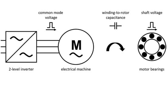
A 2-level inverter used for variable-speed operation of an electrical machine impresses a common-mode voltage into the stator winding. The intensity of the common-mode voltage for a 3-phase electrical machine is equal to the average of the three phase-to-ground voltages [
1]. The common-mode voltage causes a voltage on the rotor shaft via the winding-to-rotor capacitance. If the critical field strength of the lubricant film in the anti-friction bearing is exceeded, electric discharge machining (EDM) currents occur in the area of liquid friction/ full lubrication [
2]. Grey frosting of the raceway and the rolling element surfaces, and the periodic raceway corrugation structures can be the result of EDM bearing currents [
3]. The winding-to-rotor capacitance required to predict the shaft voltage is composed of the slot portion and the two end-winding portions [
4,
5]. The slot portion corresponds to the capacitive coupling in the active part of an electrical machine. The end-winding portions, on the other hand, represent the capacitances between the end winding and the rotor. Especially for induction machines, the end-winding portion has a large influence on the entire winding-to-rotor capacitance, due to the squirrel-cage ring [
6].
The analytical determination of the slot portion of the winding-to-rotor capacitance is mainly based on calculating a plate capacitor [
3,
5,
7,
8,
9,
10]. However, the derivation of the calculation rule of a plate capacitor is based on the assumption of a one-dimensional field area. Hence, the influence of the stator lamination is not taken into account. Therefore, correction functions are introduced in References [
3,
5]. In Reference [
11], the electric field area between the stator winding and the rotor lamination in the active part of an electrical machine is divided into a slot area and an air-gap area. The field problem for each area is solved by the separation method taking into account the continuity and the boundary conditions. It can be shown that potential fluctuations are present in the field area of the slot when assuming a stator potential of zero volts between the two slot walls. By means of the slot model, calculating the electrical potential in the center of the slot is performed at the transition between the slot and the air gap. This corresponds to the amplitude of the potential fluctuation at the transition between the slot and the air gap and serves as an input value of the air gap model. The air gap model then calculates the influenced rotor charge as a function of the potential amplitude determined in the slot model, assuming a rotor potential of zero volts. The quotient of the rotor charge and the potential of the stator winding specified in the slot model corresponds to the slot portion of the winding-to-rotor capacitance. In the calculation rule presented in Reference [
11], however, a constant slot width is assumed to solve the field area in the slot. Hence, the influence of a wedge area and a scattering space cannot be taken into account compared to the finite element method (FEM) simulations.
The current analytical determination of the end-winding portion of the winding-to-rotor capacitance is largely based on calculating a cylindrical capacitor [
12,
13,
14]. The derivation of the calculation rule of a cylindrical capacitor is based, comparable to the plate capacitor, on the assumption of a one-dimensional field area. Therefore, the influenced charge on the front surface of the rotor, and the influence of the stator lamination is not taken into account.
In Reference [
15], the field area between the end-winding and the rotor is divided into individual, simplified areas, and the entire rotor charge is determined by means of the superposition principle. The determination of the charge on the lateral surface of the rotor is performed with the calculation rule of a cylindrical capacitor. To estimate the charge on the front surface of the rotor, a simplified field area in the form of a step area is solved by the separation method. An exact solution of the entire field problem is not possible, due to the subdivision of the area into independent sections.
In this article, a novel approach for calculating the slot and the end-winding portion of the winding-to-rotor capacitance is presented, which determines the scalar potential field in the closed field area of the active part and the end-winding. The presented slot model can be used to take the slot geometry into account. In the introduced end-winding model, the influence of the stator lamination is taken into consideration. Likewise, any end-winding and rotor contour can be modeled. Overall, the two calculation models are based on the following simplifications:
The stator winding, the stator, and the rotor are electrically ideally conductive.
The media within the considered geometries consist of materials with constant permittivity.
2. Modeling Frame
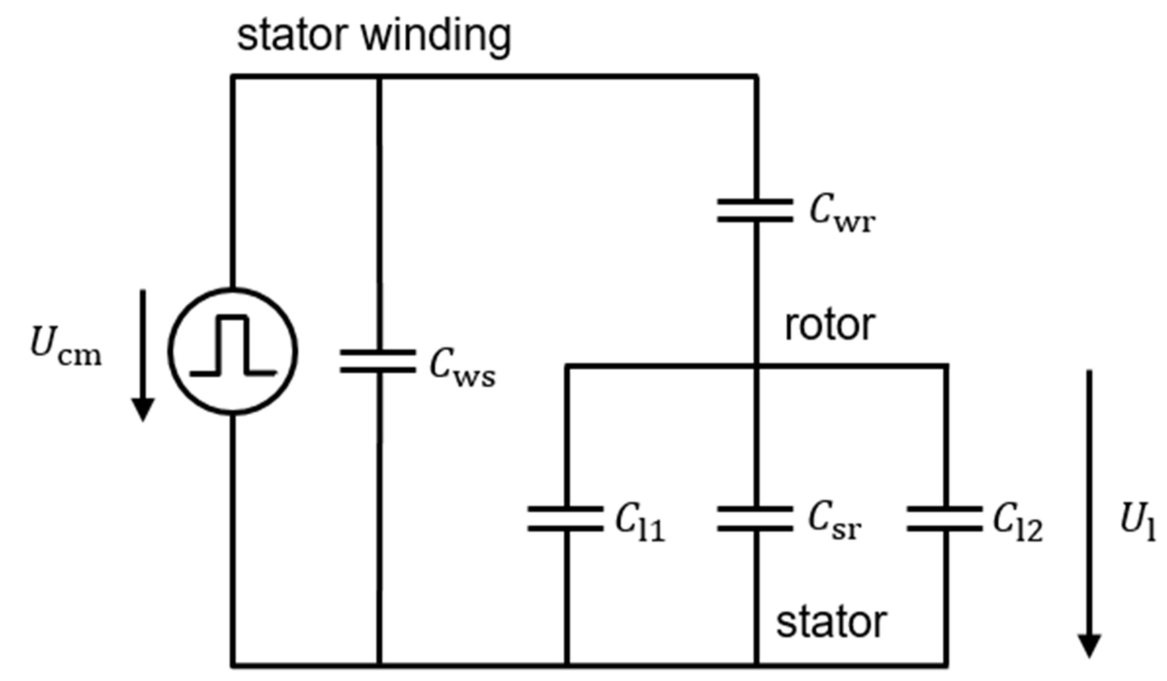
The shaft voltage
can be determined by means of the capacitive voltage divider, shown in
Figure 1 as
with the common-mode voltage
[
16]. In
Figure 1, this capacitive voltage divider connected in parallel to the winding-to-stator capacitance
, which is composed of the winding-to-rotor capacitance
, the stator-to-rotor capacitance
and the capacitances of the two bearings
and
, is decisive for the height of the shaft voltage. The stator-to-rotor capacitance can be calculated according to Reference [
17], under consideration of the stator slot and the influence of the relative permittivity of the medium in the stator slot by means of the calculation rule of a modified cylindrical capacitor. As described in
Section 1, the entire winding-to-rotor capacitance of an electrical machine
consists of the slot portion
and the two end-winding portions
and
.
The slot model used in this article is shown in
Figure 2. The slot and the air gap area are described in Cartesian coordinates.
The slot geometry of the stator consists of the width and the height of the slot opening, the width of the slot , the height of the wedge area and the height between coil and wedge area . Between the stator with the bore radius and the rotor is the air gap with the air gap width . The distance between the stator winding and the stator corresponds to the thickness of the slot insulation . The thickness of the medium with permittivity is . The number of stator slots is . The air gap is filled with a second medium of permittivity . In this stator slot model, the radial heights of the winding, the rotor, and the stator slot are not needed.
A simplified, rotationally symmetric end-winding model is shown in
Figure 3. The
z-axis and the outer radius of the stator lamination
limit the field area in radial direction. In axial direction, the area is limited by the stator lamination lying here on the
r-axis and the length of the rotor shaft
at the position of the end shield. The end winding is modeled as a hollow cylinder with the length
. The lower edge
and the upper edge
of the end winding define the radial height of the hollow cylinder. The transition from the rotor lamination with radius
to the rotor shaft with radius
takes place at the axial position
. The entire field area between stator core, stator housing, end shield, rotor shaft and rotor core, as well as the end winding is filled with material of permittivity
. In the end-winding model, the width of the stator lamination and the end shield, as well as the thickness of the stator housing, are not needed.
3. Determination of the Slot Portion of the Winding-to-Rotor Capacitance
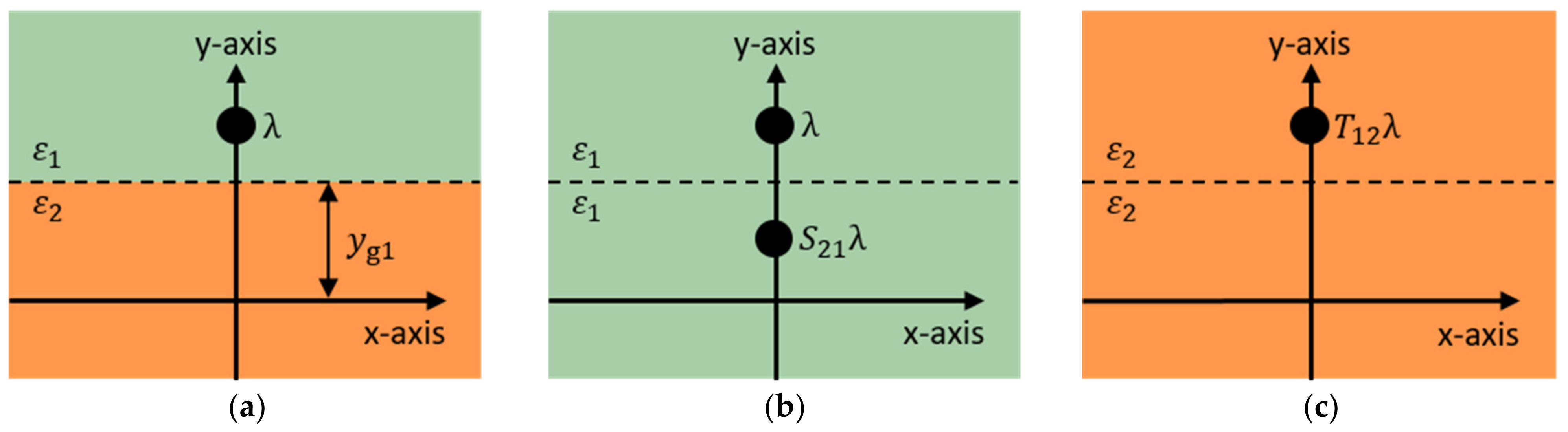
For the determination of the slot portion of the winding-to-rotor capacitance, the method of image charges is used as a solution method of the Laplace equation. Using this method, dielectric boundaries embedded in the solution area are substituted by so-called “mirror charges” and “substitute charges”. A replacement problem arises, where only natural boundary conditions occur. Subsequently, the resulting scalar potential field can be determined by superposition of the corresponding values of the scalar potential fields of the individual charges [
18].
In
Figure 4a, a line charge
is located above a dielectric boundary. The resulting scalar potential field in the medium above the dielectric boundary results from the superposition of the potential of the original line charge
and the potential of a mirror line charge
in the mirror point of
(
Figure 4b). It is assumed that the entire space is filled with material of permittivity
of the upper space area. The resulting scalar potential field below the dielectric boundary is determined by the potential of a substitute line charge
, which is located at the position of
(
Figure 4c). The substitute arrangement is filled with the permittivity
of the medium below the dielectric boundary.
The coefficients of the mirror charge and the equivalent charge are determined by the continuity conditions of the tangential component of the E-field and the normal component of the D-field at the dielectric boundary under the condition of a charge-free boundary layer [
19]
The electrodes of the stator, the stator winding, and the rotor cannot be represented by a single line charge, due to their complex geometry. For modeling purposes, the surface charges on the electrodes are substituted by an integer number of line charges [
19]. The individual line charges, which have different charge densities, are placed within the electrodes. The unknown line charge densities are determined using discrete receptor points on the contour of the electrodes. At the positions of the receptor points, the potential of the stator
, the potential of the stator winding
and the potential of the rotor
should be present.
Figure 5 shows the electrodes in the corresponding field area. In the model, the electrode of the stator is located both, above and below the dielectric boundary layer.
The electrode of the stator winding, on the other hand, is located only above, the electrode of the rotor only below the boundary layer. The three electrodes are modeled using the receptor points and the line charges, shown in
Figure 5.
The scalar potential field of a line charge is calculated as [
19]
Here,
is an arbitrary space vector, in whose coordinates the potential is determined. The vector
contains the coordinates of the line charge. The line charge density
denotes the charge per length. A line charge placed above the dielectric boundary layer, shown in
Figure 5, generates the potential field
on and above the boundary with the y-coordinate
. The first summand of the multiplier represents the potential of the original line charge. The second summand of the multiplier describes the effect of the mirror line charge. A line charge placed above the boundary layer additionally generates the potential field
in the medium below the dielectric boundary layer. A line charge, which is in contrast to
Figure 4a located below the boundary, generates the potential
in the medium below the boundary and the scalar potential field
on and above the dielectric boundary with
and
It is assumed that the three electrodes modeled in
Figure 5 consist of a set of
line charges and
receptor points. At the positions of the
receptor points, the potential can be determined using the
line charges
The coefficient matrix
represents the effect of the line charges on the potentials in the receptor points. Therefore, the elements of the coefficient matrix contain the multiplier of Equations (6), (7), (8) or (9). The elements of the coefficient matrix in the row of a receptor point, which is placed above or on the boundary, consist of the multiplier of Equations (6) or (9) depending on the positioning of the line charge. The elements of the coefficient matrix in the row of a receptor point placed below the boundary consist of the multiplier of Equations (7) or (8) depending on the addressed line charge. The distinction, whether a receptor point or a line charge is positioned above or below the boundary is based on the comparison of the y-coordinate of the receptor point or the line charge with the y-coordinate of the dielectric boundary
. The potentials in the receptor points arise from the desired potentials of the three electrodes
with the integer variable
. The unknown line charge densities result from the application of the pseudoinverse of the coefficient matrix
to
Using the values of the potentials of the W line charges, according to Equations (7) or (8), the potential in the medium of the air gap can be determined by means of superposition. The capacitance between the stator winding and the rotor in the active part
is calculated using the Maxwell capacitance coefficients [
18]. It is assumed that the electrode of the stator contains the charge
and the potential
, the electrode of the stator winding contains the charge
and the potential
and the electrode of the rotor contains the charge
and the potential
.
The corresponding capacitance coefficient matrix is
The resulting charges on the three electrodes
,
and
can be calculated according to Equation (14) by summing the line charges placed inside an electrode to
with the integer variable
. The capacitance coefficients
correspond to the capacitance
for counter capacitances
. Assuming a stator and a rotor potential of zero volts in each case, the slot portion of the winding-to-rotor capacitance is determined, according to Equation (15), as
with the number of stator slots
and the core length of the stator
.
4. Determination of the End-Winding Portion of the Winding-to-Rotor Capacitance
Instead of line charges used to determine the slot portion, ring charges are used to determine the end-winding portion. The centers of the ring charges lie on the
z-axis. The scalar potential field of a ring charge with the radius
and the z-coordinate
can be calculated in the cylindrical coordinate system to
with
And the complete elliptic integral of the first kind
[
20]. The solution of the elliptic integral
is performed numerically.
Figure 6 shows the electrodes of the stator with the potential
, of the stator winding with the potential
and of the rotor with the potential
, modeled by means of receptor points and ring charges. In order to take the stator lamination into account and consequently to limit the field area at the axial position
, the electrode of the end winding must be shifted slightly in positive z-direction. Otherwise, there would be a galvanic connection between the stator and the winding electrode. The minimum distance between the stator core and the rotor core at the axial position
corresponds to the air gap length
. The modeled electrode of the rotor extends into the negative z-range, hence, for electrical machines with identical stator and rotor core length, a simple positioning of the receptor points and ring charges of the rotor is possible. The end shield and the bearing are considered to be part of the stator electrode. At the axial position
, the stator electrode has a small distance to the rotor electrode, due to the galvanic isolation.
It is assumed that the three electrodes modeled in
Figure 6 consist of a set of
ring charges and
receptor points. At the positions of the
receptor points, the potential can be determined using the
ring charges
The coefficient matrix
represents the effect of the ring charges on the potentials in the receptor points. Therefore, the elements of the coefficient matrix contain the multiplier of Equation (18). The potentials in the receptor points
arise from the desired potentials of the three electrodes, according to Equation (13). The determination of the unknown ring charge densities is done by means of Equation (14). Using the values of the potentials of the W ring charges according to Equation (18), the potential in end-winding region can be determined by means of superposition.
Figure 7 contains the calculated equipotential surfaces of the first investigated end-winding model. The potential of the end winding was fixed to one volt and the potentials of the stator and the rotor to zero volts. It can be seen that the required potentials exist on the surfaces of the three electrodes.
The determination of the capacitance between the stator winding and the rotor in the end-winding region
is performed with the capacitance coefficient matrix in Equation (15). The resulting charges of the three electrodes
,
and
can be calculated by summing the charges of the ring charges placed inside an electrode to
with the integer variable
. Here, the circumference of the addressed ring charge must be considered.
Assuming a stator and a rotor potential of zero volts in each case, the end-winding portion of the winding-to-rotor capacitance
is determined, according to Equation (15), as
5. Results
The validation of the models is performed with the help of FEM simulations. The six investigated machine variants for calculating the slot portion of the winding-to-rotor capacitance, which differ in their geometries and material properties, are shown in
Table 1. In contrast to the presented stator slot model, the FEM simulations take into account the radius of the stator and the rotor lamination. In the slot model, the distance between the line charges and the contour of the electrodes is selected to 1 µm. The three electrodes are modeled with 4000 receptor points and 2000 line charges.
Table 2 shows the numerically determined
and analytically calculated
slot portions of the winding-to-rotor capacitance, according to Equation (17). Notably, the deviations are in the single-digit percentage range.
To take into account the radius of the stator and the rotor lamination, the potential amplitude present at the transition between the slot and the air gap in the center of the slot
can be determined with the presented slot model. Afterwards, the slot portion of the winding-to-rotor capacitance
can be calculated in the air gap model, according to Reference [
11].
Table 3 contains the analytically calculated and by means of FEM simulations determined potential amplitudes and the slot portions of the winding-to-rotor capacitance.
Again, the deviations between the potential amplitudes calculated in the presented stator slot model and those determined by means of FEM simulations are in the single-digit percentage range. The slot portions of the winding-to-rotor capacitance calculated, according to Reference [
11], have a maximum deviation of about 11% compared to FEM results.
For the validation of the determination of the end-winding portion of the winding-to-rotor capacitance, according to Equation (22), the eight end-winding models contained in
Table 4 are examined. The three electrodes in the end-winding space are modeled with 1800 receptor points and 1800 ring charges. In the end-winding model, the distance between the ring charges and the contour of the electrodes, as well as the distance of the end winding from the stator core, is 5 µm. The numerically determined and the analytically calculated end-winding portions of the winding-to-rotor capacitance and their deviations are shown in
Table 5. Notably, the deviations are in the single-digit percentage range.
6. Discussion
The small differences between the analytically calculated potential amplitudes and those determined by means of FEM simulations in
Table 3 illustrate that the complex stator slot geometry can be taken into account very well with the presented method. The assumption of a straight, non-curved rotor surface leads only to slight deviations from FEM simulations in the examined slot models. However, the air gap model presented in Reference [
11] can be used to determine the influenced charge on the rotor under consideration of the radius of the stator and the rotor surface. Especially for small-bore radii or large air gap lengths, the radius of the surfaces cannot be neglected. A consideration of the radius of the surfaces with simultaneous translation of the slot model to the correct radius does not lead to an improvement of the accuracy of the results. In Reference [
21], the influence of the numbers of charges and of receptor points and their positions on the quality of the solution is analyzed. A larger number of charges and contour points increase the accuracy of the calculation. In addition, a larger number of contour points than charges can increase the accuracy of the solution. To improve the condition of the coefficient matrix
, it is recommended in Reference [
21] to place the zero point of the coordinate system near the arrangement. Also, a small distance between a charge and the corresponding receptor point can enhance the condition of the coefficient matrix. In the slot model presented here, the zero point is located on the rotor surface, and a shift of the arrangement would worsen the condition of the coefficient matrix. At this point, it should be mentioned that the distance between the charges and the receptor points should not be chosen arbitrarily small. Otherwise, the radius of the equipotential surfaces of the charges on the modeled electrodes comes to the fore [
21].
The above recommendations also apply to the end-winding model. Notably, the deviations between the analytically calculated capacitances and those determined by means of FEM simulations in
Table 5 are small. Since only one medium can be considered in the end-winding model, the influence of a protruding insulation or potting compound cannot be analyzed. However, the influence of protruding insulation is small, due to its low radial height in the field area. In the future, more research on how other materials in the end-winding model can be considered would be useful.


