A PV-Powered TE Cooling System with Heat Recovery: Energy Balance and Environmental Impact Indicators


Abstract
1. Introduction
2. Materials and Methods
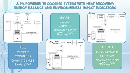
- Stage 1: The thermoelectric cooling system without heat recovery; the TE module was powered by a PV system including a PV panel, solar battery and charge controller;
- Stage 2: The thermoelectric cooling system with heat recovery; the TE module was powered by a laboratory AC/DC power supply within the power comparable to the low solar irradiance conditions;
- Stage 3: The thermoelectric cooling system with heat recovery; the TE module was powered by a solar battery.
2.1. Experimental Room
2.2. Heat Exchangers and Power Supply
2.3. Characteristics of the Measurement and Recording Systems
2.4. Statistical Processing of Data
2.5. Life Cycle Assessment of TE Cooling and Heating System
- Scenario I: 10 years of system operation, 3 working hours each day, direct PV supply
- Scenario II: 10 years of system operation, 3 working hours each day, 50% solar battery discharge, 50% direct PV supply
- Scenario III: 10 years of system operation, 3 working hours each day, electrical grid supply
- Scenario IV: 10 years of system operation, 4 working hours each day, direct PV supply
- Scenario V: 10 years of system operation, 4 working hours each day, 50% solar battery discharge, 50% direct PV supply
- Scenario VI: 10 years of system operation, 4 working hours each day, electrical grid supply
3. Results
3.1. Stage 1: TE Cooling System with Heat Dissipation Powered by PV
3.1.1. Power Supply Data
3.1.2. Temperature Performance
3.2. Stage 2: TE Cooling System with Heat Recovery Powered by PV
3.2.1. Power Supply Data
3.2.2. Temperature Performance
3.3. Stage 3: TE Cooling System with Heat Recovery Powered by Solar Battery
3.3.1. Power Supply Data
3.3.2. Temperature Performance
3.4. Statistical Processing of Data
3.4.1. Air Temperature inside the Experimental Room
3.4.2. Water Temperature inside the Tank
3.4.3. Power Supply Data
3.5. Life Cycle Assessment
4. Discussion
5. Conclusions
- 1)
- The TE modules can be successfully used for the cooling and heating purposes, with the possibility using the supply energy generated by photovoltaic modules.
- 2)
- The utilization of a PV panel, charge controller and solar battery allows keeping the supply parameters at the level required for a constant operation of the TE modules without the significant decrease in the temperature characteristics.
- 3)
- The range of supply parameter change, tested for various solar irradiance, did not affect the main functions of the tested system.
- 4)
- Within the lower supply parameters, the cooling effect of the tested system increased, while the rise of supply power caused higher temperature values at hot side of the module and increased the heating effect.
- 5)
- The COP values calculated for the tested modifications of system range from 0.055 to 1.3, which is mostly related to the change of the TE module hot side cooling; within the use of water heat exchanger, it is possible to obtain a significantly improved performance.
- 6)
- The greenhouse gas emission measured by GWP 100a indicator ranged from 0.234 to 15.277 gCO2eq/Wh, depending on the analyzed system modification, electricity source and life cycle scenario. The lowest value of the impact indicator is connected with the scenario of TE cooling system with heat recovery supplied by the direct PV panel operation.
Author Contributions
Funding
Acknowledgments
Conflicts of Interest
Appendix A
- 1)
- Production, including processed characterized in lines 1–9 in Table A1
- 2)
- Operation, including line 11
- 3)
- Final disposal, including line 12

| No | Assembly | Materials/Processes Included | Amount | Unit | Lifespan, Years |
|---|---|---|---|---|---|
| 1 | TE module | Ceramic tile 19 g, Copper 1,5 g, Tellurium, semiconductor-grade 10 g, Brazing solder 0,5 g, Metal working 1,5 g | 31 | g | 5 |
| 2 | Aluminum heat exchanger, double | Aluminum alloy, Aluminum casting | 900 | g | 10 |
| 3 | Fan, double | Fan, for power supply | 176 | g | 5 |
| 4 | Cables | Cable, unspecified | 400 | g | 5 |
| 5 | Thermal grease | Solder paste | 2 | g | 5 |
| 6 | PV panel | Photovoltaic panel, multi-Si wafer | 1.63 | m2 | 30 |
| 7 | Solar battery | Battery, Li-ion, rechargeable | 13 | kg | 15 |
| 8 | Control equipment (tracker) | Controller, charger | 0.95 | kg | 15 |
| 9 | PV cable | Cable, three-conductor | 12 | m | 15 |
| 10 | Power supply unit | Power supply unit, transformer | 3 | kg | 15 |
| 11 | Service (10 years perspective) | TE module and supplementary devices replacement | - | - | - |
| 12 | Final disposal | Mechanical treatment of waste electric and electronic equipment | 1 | kg | - |
| 13 | Electricity (grid) | Electricity mix, AC, consumption mix, at consumer, <1 kV EU-27 | 1 | Wh | - |
- 1)
- Production, including processed characterized in lines 1–13 in Table A1
- 2)
- Operation, including line 15
- 3)
- Final disposal, including line 16
| No | Assembly | Materials/Processes Included | Amount | Unit | Lifespan, Years |
|---|---|---|---|---|---|
| 1 | TE module | Ceramic tile 19 g, Copper 1,5 g, Tellurium, semiconductor-grade 10 g, Brazing solder 0,5 g, Metal working 1,5 g | 31 | g | 5 |
| 2 | Aluminum heat exchanger, single | Aluminum alloy, Aluminum casting | 450 | g | 5 |
| 3 | Fan, single | Fan, for power supply | 88 | g | 5 |
| 4 | Cables | Cable, unspecified | 400 | g | 5 |
| 5 | Thermal grease | Solder paste | 2 | g | 5 |
| 6 | Water heat exchanger connections | Polyethylene pipe, corrugated | 0.5 | m | 10 |
| 7 | Water heat exchanger | Copper, copper working | 345 | g | 10 |
| 8 | Pump | Pump for water, 9 W | 1 | p | 10 |
| 9 | Pipes insulation | Tube insulation, Synthetic rubber | 0.5 | kg | 10 |
| 10 | PV panel | Photovoltaic panel, multi-Si wafer | 1.63 | m2 | 30 |
| 11 | Solar battery | Battery, Li-ion, rechargeable | 13 | kg | 15 |
| 12 | Control equipment (tracker) | Charger | 0.95 | kg | 15 |
| 13 | PV cable | Cable, three-conductor | 12 | m | 30 |
| 14 | Power supply unit | Power supply unit, transformer | 3 | kg | 15 |
| 15 | Service (10 years perspective) | TE module and supplementary devices exchange | - | - | - |
| 16 | Final disposal | Mechanical treatment of waste electric and electronic equipment | 1 | kg | - |
| 17 | Electricity (grid) | Electricity mix, AC, consumption mix, at consumer, <1 kV EU-27 | 1 | Wh | - |
| Scenario | Processes Included | GWP (kgCO2eq) | Comment |
|---|---|---|---|
| I | Production (Table A1) Service: TE module and fans replacement Final disposal: total for TE module and partial for elements with longer lifespan Energy balance according Stage 1: Series I and II | 397.4 | PV supply system included for 10 of 30 years of usage |
| II | Production (Table A1) Service: TE module and fans replacement Final disposal: total for TE module and partial for elements with longer lifespan Energy balance according Stage 1: Series III | 420.2 | PV supply system included for 10 of 30 years of usage, battery life 30% shorter |
| III | Production (Table A1) Service: TE module and fans replacement Final disposal: total for TE module and partial for elements with longer lifespan Energy balance according Stage 1: Series I and II | 646.8 | Power supply from EU-27 low voltage grid |
| IV | Production (Table A1) Service: TE module and fans replacement Final disposal: total for TE module and partial for elements with longer lifespan Energy balance according Stage 1: Series I and II | 397.4 | PV supply system included for 10 of 30 years of usage |
| V | Production (Table A1) Service: TE module and fans replacement Final disposal: total for TE module and partial for elements with longer lifespan Energy balance according Stage 1: Series III | 420.2 | PV supply system included for 10 of 30 years of usage, battery life 30% shorter |
| VI | Production (Table A1) Service: TE module and fans replacement Final disposal: total for TE module and partial for elements with longer lifespan Energy balance according Stage 1: Series I and II | 806.0 | Power supply from EU-27 low voltage grid |
| Scenario | Processes Included | GWP (kgCO2eq) | Comment |
|---|---|---|---|
| I | Production (Table A2) Service: TE module and fan replacement Final disposal: total for TE module and partial for elements with longer lifespan Energy balance according Stage 3 | 297.4 | PV supply system included for 10 of 30 years of usage |
| II | Production (Table A2) Service: TE module and fan replacement final disposal total for TE module and partial for elements with longer lifespan Energy balance according Stage 2 | 320.2 | PV supply system included for 10 of 30 years of usage, battery life 30% shorter |
| III | Production (Table A2) Service: TE module and fan replacement Final disposal total for TE module and partial for elements with longer lifespan, Energy balance according Stage 3 | 522.9 | Power supply from EU-27 low voltage grid |
| IV | Production (Table A2) Service: TE module and fan replacement Final disposal: total for TE module and partial for elements with longer lifespan Energy balance according Stage 3 | 297.4 | PV supply system included for 10 of 30 years of usage |
| V | Production (Table A2) Service: TE module and fan replacement final disposal total for TE module and partial for elements with longer lifespan Energy balance according Stage 2 | 320.2 | PV supply system included for 10 of 30 years of usage, battery life 30% shorter |
| VI | Production (Table A2) Service: TE module and fan replacement Final disposal total for TE module and partial for elements with longer lifespan, Energy balance according Stage 3 | 674.1 | Power supply from EU-27 low voltage grid |
References
- Asdrubali, F.; Baldinelli, G.; D’Alessandro, F.; Scrucca, F. Life cycle assessment of electricity production from renewable energies: Review and results harmonization. Renew. Sust. Energy Rev. 2015, 42, 1113–1122. [Google Scholar] [CrossRef]
- Żelazna, A.; Zdyb, A.; Pawłowski, A. The influence of selected factors on PV systems environmental indicators. Ann. Environ. Protect. 2016, 18, 722–732. [Google Scholar]
- Van Ruijven, B.J.; De Cian, E.; Sue Wing, I. Amplification of future energy demand growth due to climate change. Nat. Commun. 2019, 10, 1–12. [Google Scholar] [CrossRef] [PubMed]
- Jackson, R.B.; Le Quéré, C.; Andrew, R.M.; Canadell, J.G.; Korsbakken, J.I.; Liu, Z.; Peters, G.P.; Zheng, B. Global energy growth is outpacing decarbonization. Environ. Res. Lett. 2018, 13, 120401. [Google Scholar] [CrossRef]
- Owoyele, O.; Ferguson, S.; O’Connor, B.T. Performance analysis of a thermoelectric cooler with a corrugated architecture. Appl. Energy 2015, 147, 184–191. [Google Scholar] [CrossRef]
- Gou, X.L.; Ping, H.F.; Ou, Q.; Xiao, H.; Qing, S.W. A novel thermoelectric generation system with thermal switch. Energy Procedia 2014, 61, 1713–1717. [Google Scholar] [CrossRef][Green Version]
- He, W.; Zhang, G.; Zhang, X.X.; Ji, J.; Li, G.Q.; Zhao, X.D. Recent development and application of thermoelectric generator and cooler. Appl. Energy 2015, 143, 1–25. [Google Scholar] [CrossRef]
- Zheng, X.F.; Liu, C.X.; Yan, Y.Y.; Wang, Q. A review of thermoelectrics research—Recent developments and potentials for sustainable and renewable energy applications. Renew. Sustain. Energy Rev. 2014, 32, 486–503. [Google Scholar] [CrossRef]
- Gao, Y.W.; Lv, H.; Wang, X.D.; Yan, W.M. Enhanced Peltier cooling of two-stage thermoelectric cooler via pulse currents. Int. J. Heat Mass Transf. 2017, 114, 656–663. [Google Scholar] [CrossRef]
- Teffah, K.; Zhang, Y.; Mou, X.L. Modeling and experimentation of new thermoelectric cooler–thermoelectric generator module. Energies 2018, 11, 576. [Google Scholar] [CrossRef]
- Żelazna, A.; Gołębiowska, J. Life Cycle Assessment of Cooling and Heating System Based on Peltier Module. IOP Conf. Ser. Earth Environ. Sci. 2019, 290, 012067. [Google Scholar] [CrossRef]
- Zhao, D.; Tan, G. A review of thermoelectric cooling: Materials, modeling and applications. App. Therm. Eng. 2014, 66, 15–24. [Google Scholar] [CrossRef]
- Meng, J.H.; Wang, X.D.; Zhang, X.X. Transient modeling and dynamic characteristics of thermoelectric cooler. Appl. Energy 2013, 108, 340–348. [Google Scholar] [CrossRef]
- Yazawa, K.; Shakouri, A. Optimization of power and efficiency of thermoelectric devices with asymmetric thermal contacts. J. Appl. Phys. 2012, 111, 024509. [Google Scholar] [CrossRef]
- Sahin, A.Z.; Yilbas, B.S. The thermoelement as thermoelectric power generator: Effect of leg geometry on the efficiency and power generation. Energy Convers. Manag. 2013, 65, 26–32. [Google Scholar] [CrossRef]
- Lee, H. Optimal design of thermoelectric devices with dimensional analysis. Appl. Energy 2013, 106, 79–88. [Google Scholar] [CrossRef]
- Yilbas, B.S.; Sahin, A.Z. Thermoelectric device and optimum external load parameter and slenderness ratio. Energy 2010, 35, 5380–5384. [Google Scholar] [CrossRef]
- Wang, C.C.; Hung, C.I.; Chen, W.H. Design of heat sink for improving the performance of thermoelectric generator using two-stage optimization. Energy 2012, 39, 236–245. [Google Scholar] [CrossRef]
- Twaha, S.; Zhu, J.; Yan, Y.; Li, B. A comprehensive review of thermoelectric technology: Materials, applications, modelling and performance improvement. Renew. Sustain. Energy Rev. 2016, 65, 698–726. [Google Scholar] [CrossRef]
- Naphon, P.; Wiriyasart, S. Liquid cooling in the mini-rectangular fin heat sink with and without thermoelectric for CPU. Int. Commun. Heat Mass Transf. 2009, 36, 166–171. [Google Scholar] [CrossRef]
- Gao, X.; Chen, M.; Snyder, G.J.; Andreasen, S.J.; Kær, S.K. Thermal management optimization of a thermoelectric-integrated methanol evaporator using a compact CFD modeling approach. J. Electron. Mater. 2013, 42, 2035–2042. [Google Scholar] [CrossRef]
- Vian, J.G.; Astrain, D. Development of a heat exchanger for the cold side of a thermoelectric module. Appl. Therm. Eng. 2008, 28, 1514–1521. [Google Scholar] [CrossRef]
- Taylor, R.A.; Solbrekken, G.L. Comprehensive system-level optimization of thermoelectric devices for electronic cooling applications. IEEE Trans. Compon. Packag. Technol. 2008, 31, 23–31. [Google Scholar] [CrossRef]
- David, B.; Ramousse, J.; Luo, L. Optimization of thermoelectric heat pumps by operating condition management and heat exchanger design. Energy Convers. Manag. 2012, 60, 125–133. [Google Scholar] [CrossRef]
- Cosnier, M.; Fraisse, G.; Luo, L. An experimental and numerical study of a thermoelectric air-cooling and air-heating system. Int. J. Refrig. 2008, 31, 1051–1062. [Google Scholar] [CrossRef]
- Liu, Z.B.; Zhang, L.; Gong, G.C.; Luo, Y.Q.; Meng, F.F. Experimental study and performance analysis of a solar thermoelectric air conditioner with hot water supply. Energy Build. 2015, 86, 619–625. [Google Scholar] [CrossRef]
- Ma, X.; Zhao, H.; Zhao, X.; Li, G.; Shittu, S. Building Integrated Thermoelectric Air Conditioners—A Potentially Fully Environmentally Friendly Solution in Building Services. Future Cities Environ. 2019, 5, 1–13. [Google Scholar] [CrossRef]
- Cheng, T.C.; Cheng, C.H.; Huang, Z.Z.; Liao, G.C. Development of an energy-saving module via combination of solar cells and thermoelectric coolers for green building applications. Energy 2011, 36, 133–140. [Google Scholar] [CrossRef]
- Liu, Z.; Zhang, L.; Gong, G.; Han, T. Experimental evaluation of an active solar thermoelectric radiant wall system. Energy Convers. Manag. 2015, 94, 253–260. [Google Scholar] [CrossRef]
- Gołębiowska, J.; Żelazna, A. Experimental investigation of thermoelectric cooling system with heat recovery. EDP Sci. E3S Web Conf. 2019, 100, 00020. [Google Scholar] [CrossRef]
- Ecoinvent. Available online: www.ecoinvent.org (accessed on 10 February 2020).
- Greenhouse Gas Protocol. Available online: www.https://ghgprotocol.org (accessed on 10 February 2020).
- Abdul-Wahab, S.A.; Elkamel, A.; Al-Damkhi, A.M.; Is’haq, A.; Al-Rubai’ey, H.S.; Al-Battashi, A.K.; Al-Tamimi, A.R.; Al-Mamari, K.H.; Chutani, M.U. Design and experimental investigation of portable solar thermoelectric refrigerator. Renew. Energy 2009, 34, 30–34. [Google Scholar] [CrossRef]
- Astrain, D.; Via, J.G.; Albizua, J. Study and optimization of the heat dissipater of a thermoelectric refrigerator. Appl. Therm. Eng. 2005, 25, 3149–3162. [Google Scholar] [CrossRef]
- Hermes, C.J.L.; Barbosa, J.R. Thermodynamic comparison of Peltier, Stirling, and vapor compression portable coolers. Appl. Energy 2012, 91, 51–58. [Google Scholar] [CrossRef]
- Min, G.; Rowe, D.M. Experimental evaluation of prototype thermoelectric domestic-refrigerators. Appl. Energy 2006, 83, 133–152. [Google Scholar] [CrossRef]
- Moore, A.D.; Urmee, T.; Bahri, P.A.; Rezvani, S.; Baverstock, G.F. Life cycle assessment of domestic hot water systems in Australia. Renew. Energy 2017, 103, 187–196. [Google Scholar] [CrossRef]
- Żelazna, A. The Influence of Collector Type on Emission Indicators in Solar Systems Life Cycle Assessment. Ann. Environ. Protect. 2013, 15, 258–271. [Google Scholar]


| TE Material | Operation Temperature (K) | Max. ZT Value |
|---|---|---|
| Bi2Te3 | <150 | 0.8–1.0 |
| PbTe | 150–500 | 0.7–0.8 |
| TeAgGeSb (TAGS) | 1.2 | |
| CoSb3 | 500–700 | 0.8 |
| CeFe4Sb12 | 1.1 | |
| SiGe | 700–1000 | 0.6–1.3 |
| LaTe | 0.4 |
| Characteristic Parameter | Value |
|---|---|
| Nominal voltage | 15.5 V |
| Max. amperage | 8.5 A |
| Max. thermal output | 72 W |
| Max. temperature difference between the hot and cold sides | 71 K |
| Dimensions (length × width × height) | 40 mm × 40 mm × 3.4 mm |
| Series Number | Supply Power (W) | Energy Used (Wh) | Energy Generated (Wh) | COP - |
|---|---|---|---|---|
| Series I | 69.4 | 42.7 | 2.3 | 0.054 |
| Series II | 65.9 | 40.7 | 2.1 | 0.051 |
| Series III | 60.3 | 26.1 | 1.5 | 0.059 |
| Stage Number | Air Temperature (°C) | Water Temperature (°C) | ||||||
|---|---|---|---|---|---|---|---|---|
| Initial | Final | Mean | Median | Initial | Final | Mean | Median | |
| Stage 1 | 23.0 | 16.0 | 18.2 | 17.8 | - 1 | - 1 | - 1 | - 1 |
| Stage 2 | 19.9 | 5.2 | 4.7 | 3.6 | 10.5 | 40.3 | 26.4 | 27.0 |
| Stage 3 | 20.7 | 5.6 | 5.0 | 3.9 | 10.4 | 39.8 | 26.8 | 27.6 |
| T. stage 1 | T. stage 2 | T. stage 3 | |
|---|---|---|---|
| T. stage 1 | - | 0.991 | 0.991 |
| T. stage 2 | 0.991 | - | 0.997 |
| T. stage 3 | 0.991 | 0.997 | - |
| Stage Number | Momentary Power (W) | |||
|---|---|---|---|---|
| Initial | Final | Mean | Standard deviation | |
| Stage 1 | 72.2 | 62.8 | 65.3 | 2.0 |
| Stage 2 | 51.0 | 65.8 | 58.7 | 4.4 |
| Stage 3 | 78.7 | 62.3 | 68.7 | 5.0 |
| Global Warming Potential (gCO2eq/Wh) | |||||
|---|---|---|---|---|---|
| Scenario I | Scenario II | Scenario III | Scenario IV | Scenario V | Scenario VI |
| 9.386 | 9.514 | 15.277 | 7.039 | 7.136 | 14.278 |
| Global Warming Potential (gCO2eq/Wh) | |||||
|---|---|---|---|---|---|
| Scenario I | Scenario II | Scenario III | Scenario IV | Scenario V | Scenario VI |
| 0.312 | 0.324 | 0.548 | 0.234 | 0.243 | 0.530 |
| Reduction of GWP (%) | ||||||
|---|---|---|---|---|---|---|
| Scenario | I | II | III | IV | V | VI |
| TEC 1 | 20% | 21% | 8% | 20% | 21% | 7% |
| TEC&H 2 | 10% | 13% | 2% | 10% | 13% | 1% |
| COP | Type of Heat Exchanger | Reference |
|---|---|---|
| 0.16–0.64 | CS 1, HS 2: finned heat sink and fan | [33,34,35] |
| 0.3–4.51 | CS 1: finned heat sink and fan HS 2: water heat exchanger | [26,30,36] |
| 0.055 | CS 1, HS 2: finned heat sink and fan | Current study, Stage 1 |
| 1.25–1.3 | CS 1: finned heat sink and fan HS 2: water heat exchanger | Current study, Stage 2–3 |
© 2020 by the authors. Licensee MDPI, Basel, Switzerland. This article is an open access article distributed under the terms and conditions of the Creative Commons Attribution (CC BY) license (http://creativecommons.org/licenses/by/4.0/).
Share and Cite
Żelazna, A.; Gołębiowska, J. A PV-Powered TE Cooling System with Heat Recovery: Energy Balance and Environmental Impact Indicators. Energies 2020, 13, 1701. https://doi.org/10.3390/en13071701
Żelazna A, Gołębiowska J. A PV-Powered TE Cooling System with Heat Recovery: Energy Balance and Environmental Impact Indicators. Energies. 2020; 13(7):1701. https://doi.org/10.3390/en13071701
Chicago/Turabian StyleŻelazna, Agnieszka, and Justyna Gołębiowska. 2020. "A PV-Powered TE Cooling System with Heat Recovery: Energy Balance and Environmental Impact Indicators" Energies 13, no. 7: 1701. https://doi.org/10.3390/en13071701
APA StyleŻelazna, A., & Gołębiowska, J. (2020). A PV-Powered TE Cooling System with Heat Recovery: Energy Balance and Environmental Impact Indicators. Energies, 13(7), 1701. https://doi.org/10.3390/en13071701