Abstract
Achieving a wireless power transfer (WPT) link insensitive to separation is a key challenge to achieving power autonomy through wireless-powering and wireless energy harvesting over a longer range. While coupled WPT has been widely used for near-field high-efficiency WPT applications, the efficiency of the WPT link is highly sensitive to separation and alignment, making it unsuitable for mobile systems with unknown or loose coupling such as wearables. On the other hand, while ultra-high frequency (UHF) and microwave uncoupled radiative WPT (0.3–3 GHz) enables meters-long separation between the transmitter and the receivers, the end-to-end efficiency of the WPT link is adversely limited by the propagation losses. This work proposes radiative WPT, in the 6.78 MHz license-free band, as a hybrid solution to separation-independent WPT, thus mitigating the losses associated with coil separation. Resonant electrically small antennas were fabricated using embroidered textile coils and tuned using L-matching networks, for wearable WPT. The antenna’s efficiency and near-fields have been evaluated numerically and experimentally. The proposed WPT link achieves a stable forward transmission of S dB and S28 dB, independent of coil separation on the XZ and XY planes respectively, in a 27 m volume space. The presented approach demonstrates the highest WPT link efficiency at more than 1-m separation and promises higher end-to-end efficiency compared to UHF WPT.
1. Introduction
Meeting the energy demands of a connected world is an increasingly growing challenge. Energy harvesting and scavenging, down to W levels, is increasingly seen as a solution to the foreseen shortage in energy storage devices. To illustrate, while low power energy harvesting, transport and storage techniques are limited to applications such as sensor nodes and assisted living in smart cities, achieving power autonomy in ubiquitous internet of things devices reduces their demand for energy storage devices. Therefore, as fewer devices will require batteries, the competition for Lithium, a limited resource, can be minimized. Potentially allowing batteries to be exclusively used in high-end applications such as electric vehicles and smart grids [1,2].
Body-centric energy harvesting has been extensively explored. Piezoelectric [3], thermoelectric [4] and triboelectric energy harvesters [5], have been reported for harvesting energy generated from the human body. Furthermore, ambient harvesters such as solar cells [6], as well as microwave and mmWave rectennas have been designed on textile substrates [7,8], towards achieving power autonomy of wearable devices. A key limitation of such harvesters is their reliance on certain body-positions where the energy is generated such as the foot [3] or friction points [5]. Thus, the challenge of on-body position-independent energy transfer on textiles remains unsolved. A hybrid approach between body-centric energy harvesting and full-reliance on energy storage is wireless charging of e-textile electronics using inductive power transfer or magnetic resonance using flexible coils [9,10]. In [11], a switched-reluctance generator has been proposed as an on-bicycle power supply for textile-based sensing and communication through wireless power transmission from the bicycle to the body.
Wireless Power Transfer (WPT) is an increasingly popular method of delivering power to an electronic system [12,13]. While established applications of inductive WPT are omnipresent in the consumer electronics market and electric vehicle charging, the next generations of WPT devices will be based on resonant coupling to allow for increased separation between the transmitter and the receiver, in addition to non-coupled methods, through far-field propagation of WPT-specific waveforms. A particularly interesting platform for WPT is wearable e-textile applications, where establishing a real connection to the power supply is not feasible, and traditional energy harvesters require complex fabrication techniques to be integrated in textiles and flexible materials, or require specific on-body positioning [3,4,5,6]. Therefore, delivering power wirelessly to a wearable device represents a simple way of charging wearable nodes [14].
A hybrid approach combining sub-100 MHz WPT and radiative WPT could be adopted to mitigate the propagation losses and simplify the matching network design, improving the maximum achievable rectification efficiency. This work proposes radiative WPT using impedance-matched resonant electrically small coils, at 6.78 MHz. The proposed frequency band and antenna design reduce the complexity and cost of designing a matching network and maintain a stable WPT efficiency regardless of the coil’s separation. This paper discusses the motivation behind the radiative WPT at 6.78 MHz, the fabrication of fully textile coils for WPT, theoretically and experimentally discusses the limitations of electrically small coils for WPT, and evaluates the performance of the system under different operation conditions.
2. Radiative 6.78 MHz WPT and System Architecture
2.1. WPT: The Existing Approaches
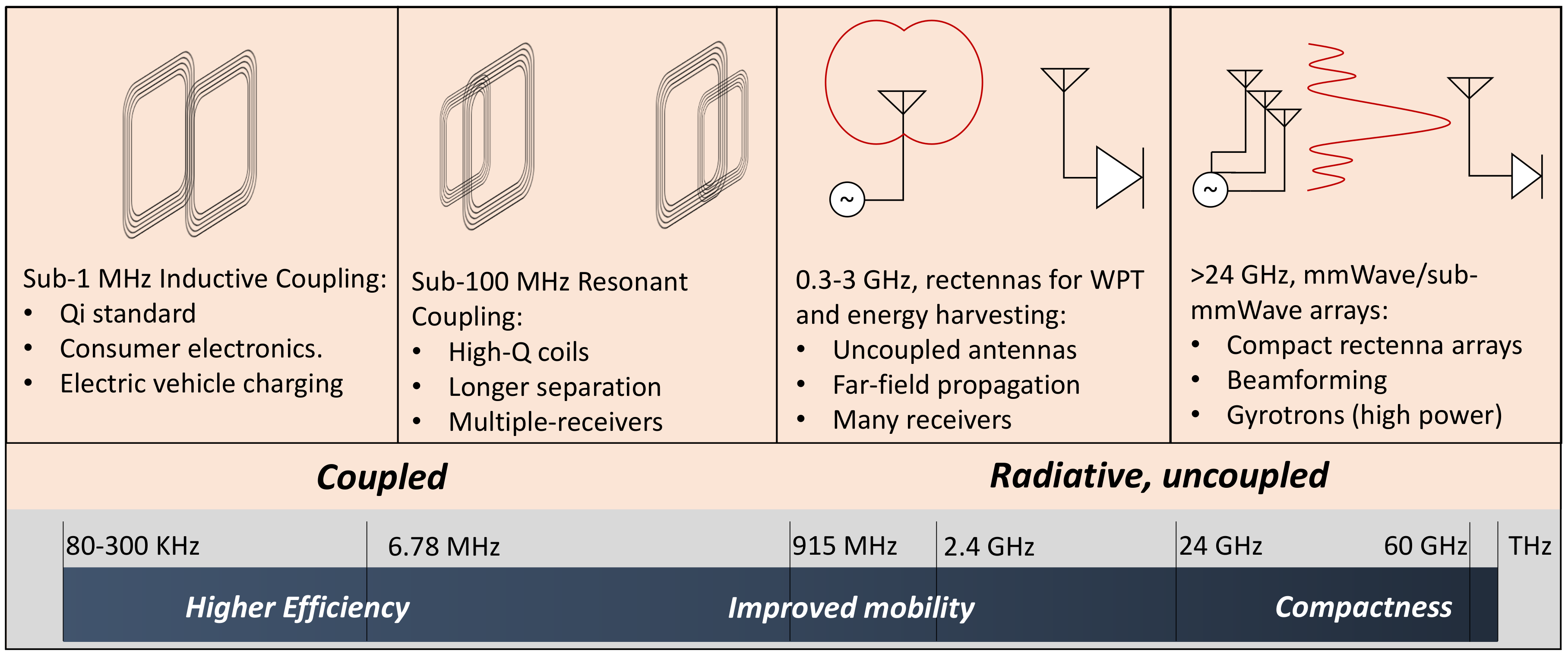
The broadband spectrum of WPT research can be summarized in multiple tracks, based on their frequency of operation and subsequently the application. Figure 1 shows examples of the most-reported WPT approaches. At lower frequencies, resonant and non-resonant (inductive WPT) coupled coils are used for high-efficiency WPT between two or more coils in consumer electronics and EV applications. Such technique is capable of handling kilowatts of power and is well-characterized and regulated [15]. Strongly coupled magnetic resonance, achieved using a tuned intermediate resonator between the transmitter and the receiver, has been demonstrated with high efficiencies at a few meters separation between the coils [16].
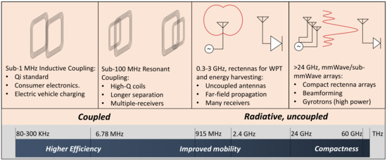
Figure 1.
The current WPT research spectrum: sub-MHz Qi-standard WPT [15], coupled magnetic resonance [16], rectennas for UHF WPT [17,18], mmWave, sub-mmWave and THz optical rectennas [19,20].
In coupled WPT, efficiencies higher than 80% have been widely reported in wearable applications [21], nevertheless, most closely coupled resonant systems are not efficient beyond 20 cm of separation s [14]. This is attributed to the WPT efficiency being proportional to [22], as opposed to in free-space propagation. Therefore, coupled WPT approaches are limited in the distance achieved. In addition, at very close separations, magnetic resonance WPT systems are prone to over-coupling and require reconfigurable tuning circuitry for re-tuning the coils in over-coupling and under-coupling regions [23,24].
At UHF and microwave bands, WPT is implemented using electromagnetic radiative rectennas, commonly formed of a resonant distributed elements antenna (i.e., not requiring lumped components matching) and a rectifier. Based on their application: harvesting ambient radio-frequency signals or receiving power from a dedicated feed; multiple antenna and rectifier designs have been proposed [7]. The key advantages of this approach is the absence of a coupling link between the transmitter and the receiver, allowing more spatial freedom. Furthermore, this technique allows many receivers to be powered using the same source. At millimeter-wave bands and beyond (THz and infrared) large antenna arrays and nano-rectennas are used in power-beaming applications with power handling capabilities in the kW regime [20].
The far-field WPT end-to-end efficiency is significantly suppressed by the propagation losses, given by the Friis formula (1), where is the transmitted power, and are the transmitter and receiver gain, respectively, is the free-space wavelength and d is the separation between the transmitting and receiving antennas.
For example, in ambient RFEH, the reported power densities rarely exceed W/cm due to the separation between the base-station and the rectenna [25]. In addition, indoor RF power densities are adversely reduced due to the absence of a direct line-of-sight, as well as the multi-path effects, resulting in over 10 dB reduction of the measured power densities [17].
It is observed from (1) that the power at the receiver is inversely proportional to the distance and frequency squared ( = 3 × 10/frequency). This implies less than 1% end-to-end forward transmission (S<−20 dB), for separations over 1 m at UHF bands. While antenna arrays and beamforming can be used to improve the power delivered to the receiver without increasing the transmitted power (through higher G), the maximum transmitter gain and power are limited by regulatory bodies such as the Federal Communications Commission (FCC) under the Equivalent Isotropic Radiated Power (EIRP) limit.
An additional challenge at higher frequencies lies in the RF to DC converter, the rectifier. While rectifying antennas (rectennas) in theory achieve up to 100% efficiency, the voltage drop across the diode, and the reflection at the diode’s input imply that the RF-DC efficiency is bottle-necked, especially at power levels below −10 dBm (100 W). Furthermore, the design of a matching network becomes more complicated at higher frequencies due to the necessity of characterizing the diode’s packaging parasitic at the frequency of interest.
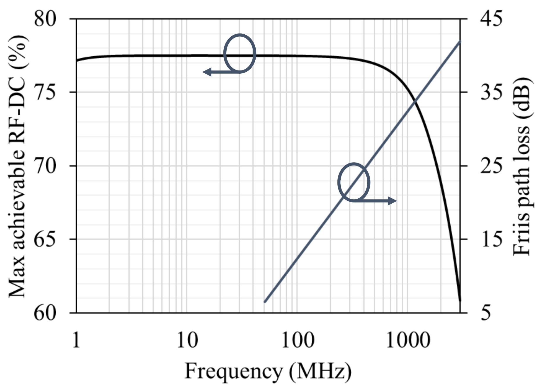
To illustrate the WPT challenges at microwave frequencies, the propagation losses at UHF bands have been calculated using (1) at 1 m separation, demonstrating the logarithmic increase in propagation losses with frequency. Furthermore, a low-barrier Schottky diode (Skyworks SMS7630), widely used in rectenna-design studies, has been simulated using harmonic balance in Keysight Advance Design Systems (ADS) to calculate its maximum achievable RF-DC efficiency assuming ideal impedance matching, at 0 dBm, using a 50 source. Figure 2 shows the decrease of the maximum RF-DC efficiency at microwave bands along with the logarithmic increase in propagation losses with frequency.

Figure 2.
Maximum achievable RF-DC efficiency simulated using non-linear harmonic balance, and the propagation losses (Friis model at 1 m) over frequency.
Despite the significant propagation losses in far-field WPT, the key advantage to far-field rectennas over inductive (resonant or non-resonant) WPT is the absence coupling link, where a radiative system is able to achieve more position freedom at the expense of efficiency, due to relying on far-field propagation for power transmission. On the other hand, the coupled approaches rely on the coils’ mutual inductance to achieve higher WPT efficiency. Therefore, the efficiency is generally proportional to [22].
2.2. Radiative Near-Field WPT
Motivated by overcoming the path losses and RF-DC inefficiencies observed in Figure 1, and overcoming the inverse-square relation with the propagation distance, selecting a sub-10 MHz WPT carrier frequency becomes an apparent choice. Where the radiative nature of the proposed approach allows coupling-free WPT, multiple receivers support, and the potential to achieve higher separation distances. The 6.78 MHz Industrial Scientific and Medical (ISM) band has been selected as the design frequency in this work. At 6.78 MHz the specified limits by the FCC are a maximum electric field of 30 V/m (−45.7 dBm), measured at 30 meters from the source. Moreover, in certain biomedical applications, the FCC has approved a waiver of the limit for up to 200.2 V/m (−29.2 dBm) for a wirelessly powered device demonstrating minimal interference with the surroundings [26]. While such low power limits constrain this WPT technology to ultra-low power applications, multiple systems have been presented with sub-W power consumption for implants and biomedical applications, which justify the need for separation-independent WPT even if it is only achievable in the W-range [19].
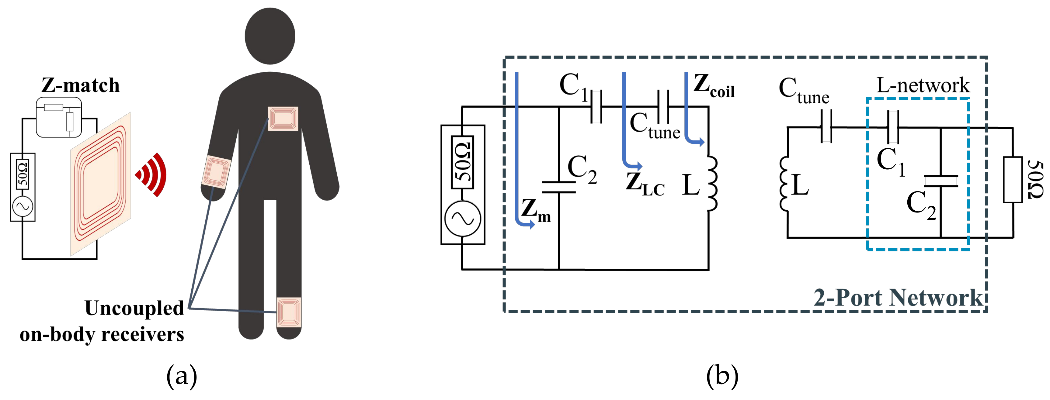
The proposed system, shown in Figure 3, uses impedance-matched coils to radiate at 6.78 MHz; acting as electrically small antennas. A sub-100 MHz carrier benefits from lower propagation losses and free positioning, compared to UHF bands and coupled WPT, respectively. As the focus of this work is investigating the efficiency of the WPT link, the WPT system (the coils and their matching network) is evaluated as a black box using its scattering-parameters (s-parameters) matrix. The forward transmission (S) is the main parameter measured in this work, which can be used to calculate the WPT efficiency using =|S|. Using s-parameters for evaluating WPT through an electromagnetic black box or for near-field applications has been previously widely used to simplify the problem where the electromagnetic medium is difficult to model (such as on-body operation) [27]. The transmitter and receiver coils and their matching network are symmetric as both are matched to 50 transceivers.

Figure 3.
The proposed uncoupled radiative WPT: (a) system architecture, (b) 2-coil system schematic and impedance matching approach.
3. Textile WPT Coils Design and Fabrication
The main area-consuming component in a WPT system is the coil or the antenna, where the size can affect the maximum achievable WPT efficiency. Therefore, the coils are the only component from Figure 3 implemented on textile, as the capacitors could be realized using low footprint surface mount components or an on-chip capacitor bank integrated with the wireless power transmission or sensing circuitry on the same system-on-chip. The geometry of the coils has been based on a standard planar coil geometry for ease of fabrication and design.
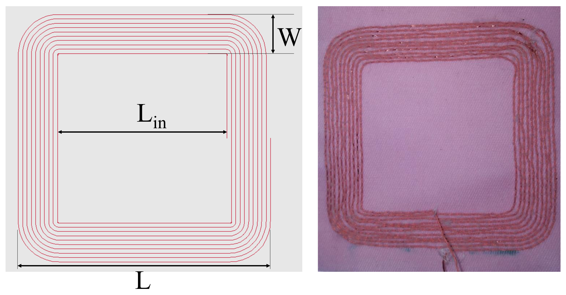
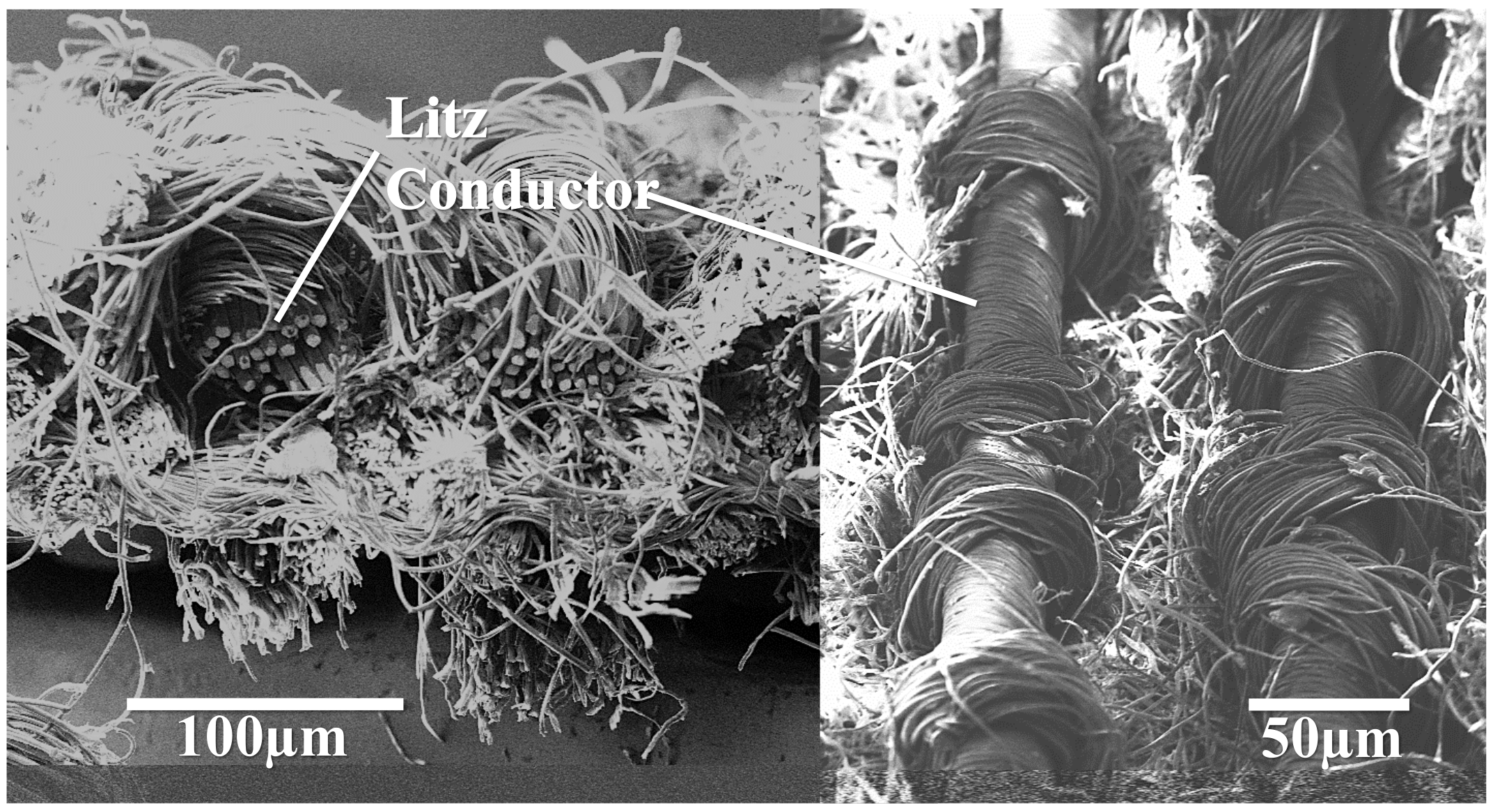
Multiple fabrication techniques have been proposed to realize WPT coils on textiles [9,10], with the main affected coil parameter by the fabrication technique being the series resistance. For example, conductive inks normally have a sheet resistance of more than 1 /square. Therefore, silk-coated copper Litz wires are chosen as the conductive material. Given their 40 m thickness, they are expected to have minimal impact on the fabric’s flexibility and hence the user’s comfort. The coils are embroidered to a 350 m-thick polyester-cotton textile substrate using an automated embroidery machine using a CAD model, the coil has been design using EAGLE, a commercial PCB design package. Figure 4 shows the layout and photograph of textile coils. A cross-section scanning-electron microscope photograph of the coils, showing the Litz conductors is shown in Figure 5.

Figure 4.
Layout and photograph of the fabricated textile coil. Dimensions (in mm): L = 60, L = 40, W = 10.
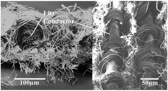
Figure 5.
SEM cross-section (Left) and top view (Right) of the fabricated coil showing the conductive Litz wires embedded within the fabric.
While the geometry of the coils is not critical in this work, the coil dimensions have been chosen to increase the inductance reducing the size of C required to achieve resonance. To illustrate, as the input impedance of the tuned coils will be experimentally measured, fabrication imperfections can be countered when designing and calculating the matching network. In terms of WPT efficiency, once the coils are matched the geometry is expected to have minimal impact on the WPT efficiency. To illustrate, the matched coil will always operate as an electrically small antenna and the minor changes in the geometry remain insignificant compared to the wavelength at 6.78 MHz, which implies minimal effect on the antenna’s radiation efficiency. The coil parameters were measured at 6.78 MHz using an impedance analyzer, the Quality factor (Q) has been calculated using at 6.78 MHz. The measured coil parameters are L = 10.2 H, R = 1.32 and Q = 329 (dimensionless).
4. Electrically Small 6.78 MHz Wearable WPT Antennas
For the coils to act as radiative antennas, the coils need to resonate at 6.78 MHz, and have their impedance matched to the source and load. The coils are tuned at 6.78 MHz using a tuning capacitor calculated using (2).
To match the coil to the source, in this case a 50 generator, the input impedance of the tuned coil is then measured using a VNA) to design a matching network. When the coil’s impedance is matched to the load, the power will be accepted by the coils and a subsequently a portion will be radiated, depending on the coil’s geometry. However, as the coil’s size is significantly smaller than the wavelength (coil perimeter = 24 cm, = 44 m), the radiation efficiency of the coils is expected to be very small, and to be the main limiting factor of the WPT efficiency. Nevertheless, as separation independence is expected the loss term will be constant across variable separation.
4.1. Coil Impedance Matching
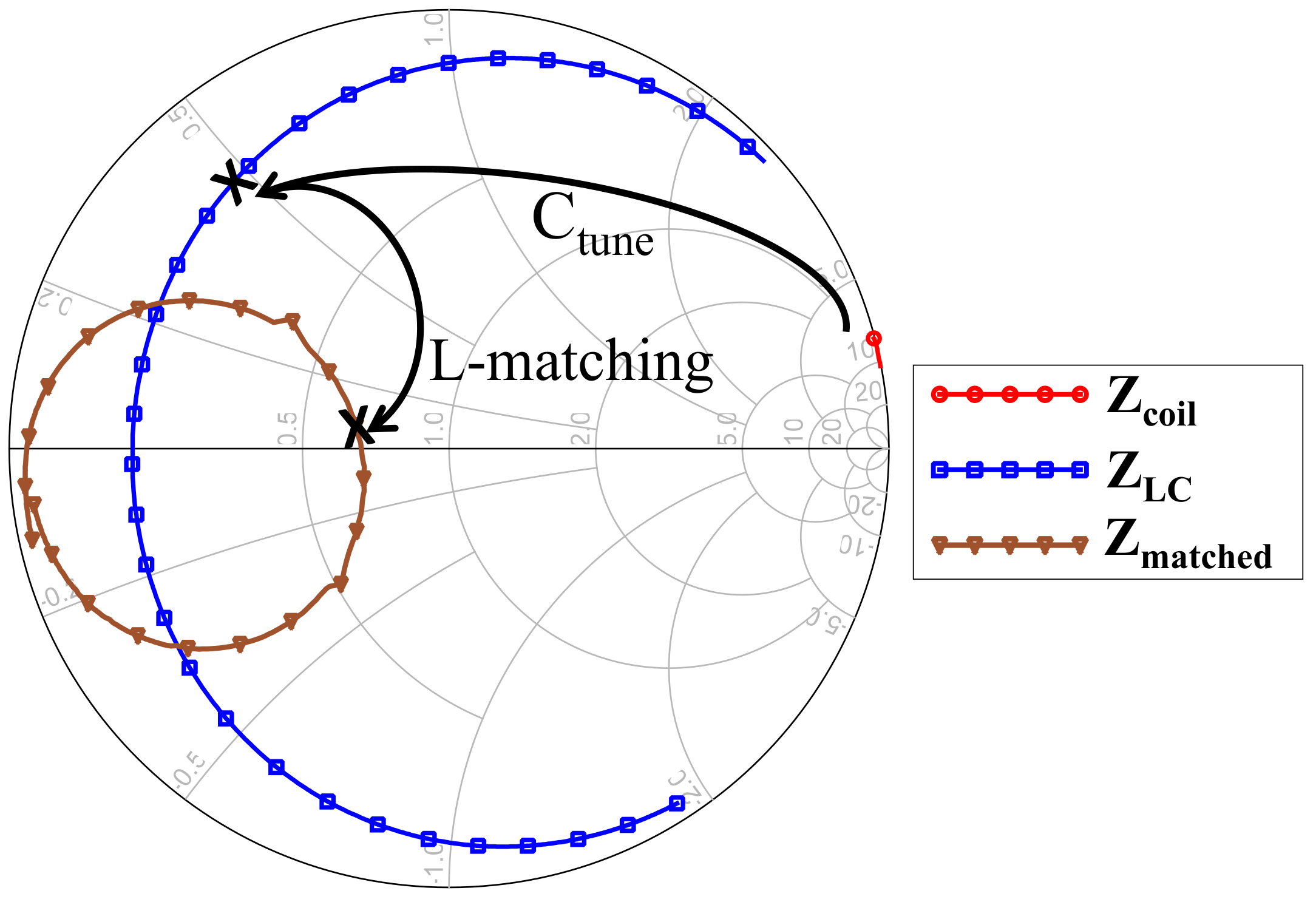
A capacitive L-matching network is designed to match Z to 50 , for compatibility with standard lab equipment. Under real operation conditions, the matching network could be designed to match the coil’s impedance to the input impedance of the rectifier at the wireless receivers, and to the power amplifier at the transmitter. Figure 6 shows the impedance matching procedure on the smith chart, as well as the measured impedance of the matched coil, acting as an electrically small antenna.

Figure 6.
Smith chart plot showing the measured coils input impedance at different matching stages: (1) coil’s inductive impedance, (2) resonant coil using C-tuning, (3) impedance-matched radiating coil.
The L-network will be composed of a shunt and a series capacitor, as observed in Figure 3, since the source impedance is greater than the load impedance (). For a capacitive network, the values of the capacitors can be calculated at the design frequency (f = 6.78 MHz) using (3)–(6).
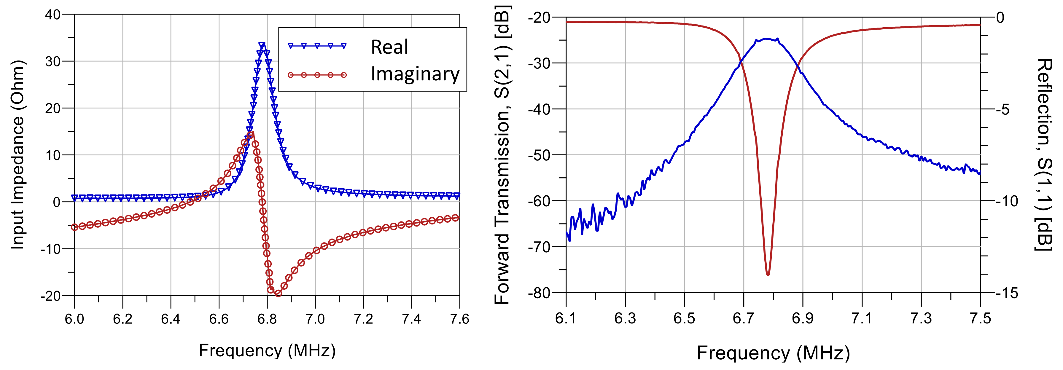
where X is the impedance of the parallel or series capacitor. Given the measured input impedance of Z = 4.35 + j21.3 , the calculated capacitor values are C = 1.5 nF and C = 3.3 nF. The input impedance of the coil after the impedance is matched to 50 , using lumped ceramic capacitors, is observed to approach the normalized optimum impedance on the smith chart, with no reactive component. Figure 7 shows the measured input impedance of the coil, and the two-port s-parameters of symmetric coils placed at 10-cm apart from each other, to ensure minimal mutual coupling between the coils. While the impedance-matched coils are demonstrated for WPT applications, the same approach can be used in wireless communication such as long-range RF-ID. This is because the demonstrated forward transmission falls within the sensitivity of most modern wireless receivers and low-noise amplifiers.

Figure 7.
Measured coil input impedance (Left) and two-port s-parameters of symmetric matched coils at 10-cm separation (right).
4.2. Analytical Antenna Efficiency
The radiation efficiency of an antenna represents the ratio of the power radiated in space, to the power accepted from the source excluding impedance mismatch losses. An electrically small loop antenna can be considered using its equivalent circuit formed of a series inductor, the loop’s Ohmic resistance , representing the power dissipated in the conductors in the form of heat, and a radiation resistance representing the power radiated to space. The radiation efficiency of an antenna is given by the ratio of to the total antenna’s resistance [28].
To overcome the difficulty of measuring and , the total resistance can be analytically calculated from the antenna’s Quality factor Q and the loop’s inductance L (8). Q can be calculated from the bandwidth using . The bandwidth defines the frequency bandwidth where [28]. To calculate the radiation efficiency, needs to be estimated using (9).
represents the size of an electrically small loop antenna, where a is the loop’s radius and . A standard approximate term for a single-turn loop antenna’s radiation resistance is given by (10), as a function of the loop’s area [28]. As the coil in this work resembles a square, s is given by . For a multi-turn loop, N is the number of coil turns.
4.3. Wheeler Cap Antenna Efficiency Measurement
The Wheeler Cap method, proposed to measure the radiation efficiency without the need for an anechoic test range, has been used to measure the of the matched textile antenna. The method can be summarized in covering the radiating antenna using a “cap” shorted to the antenna’s ground, hence confining the radiated power to the antenna’s ground return path. Therefore, the measured antenna’s input impedance no longer represents and is only composed of . The input impedance measurement is then repeated in absence of the cap to obtain , is then calculated from the difference between and [29].
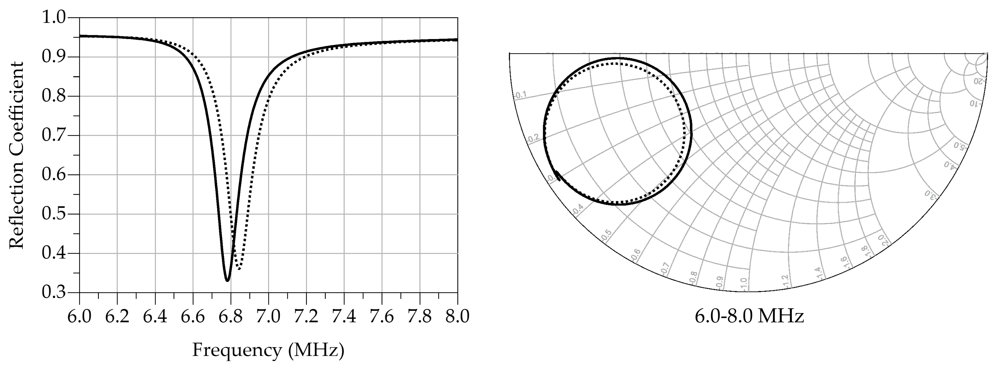
To improve the repeatability of the measured efficiency the input impedance was measured twice in the presence and absence of the cap. A VNA was used to measure the input impedance in a similar manner to that described in the previous section. Figure 8 shows the measured antenna’s response in the presence and absence of the Wheeler Cap, the difference in the reflection coefficient magnitude observed when the cap is present represents the power radiated by the antenna.

Figure 8.
One-port antenna measurements in the presence (dashed) and absence (solid) of the Wheeler Cap: (Left) magnitude response, (Right) complex input impedance.
From the Smith chart in Figure 8, the average measured = 26.584 , and , the average calculated radiation efficiency dB.
5. Performance Evaluation
5.1. Coil Near-Field Simulation and Measurement
The near-field magnetic-field emissions from the coil were measured at various separations using a near-field probe. Should the proposed coils be used in the far-field region, multiple methods were reported in the literature to evaluate the far-field radiation properties based on near-field scans [30].
A VNA has been used to measure the H-field as the forward transmission between the coil and an H-field probe. The probe used is the Rhode and Schwarz RS H400-1, providing the average magnetic field across its 25 mm radius. While the probe is designed for signals higher than 30 MHz, the manufacturer’s parameters show additional attenuation of approximately −10 dB, the measured magnitudes can be normalized using the probe’s attenuation.
To capture the magnetic field at different positions around the coil, and to aid in validating the simulation model, the average H-field across the probe was measured at three different positions: center of the coil, corner and edge of the coil turns. Figure 9 shows the test setup as well as the probe positions on the coil.

Figure 9.
Test setup for measuring the near H-field of the coil: (a) schematic, (b) probe positions on the coil surface, (c) photograph of the setup.
A 3D model of the coils has been built in CST Microwave Studio to observe the coil’s near-field and cross validate the measurements. The coil was modelled using a standard lossy copper model and matched using ideal capacitors. A field monitor at 6.78 MHz was used to observe the H-field near the coil, the field at points A, B, and C form Figure 9. The H-field has been measured as the magnitude of the forward transmission |S| between the VNA ports, where the normalized H-field was obtained using the maximum H-field measured across the three measurement points. The absolute measured maximum H-field is −10.76 dB compared to −45.5 dB, from the 3D CST simulation model. Figure 10 shows the simulated and measured near-field scans, along with the simulated H-field plot at the surface of the coil.

Figure 10.
Near-field scans of the coil: (a) measured two-port transmission between the coil and the H-field prob, (b) simulated and measured normalized H-field at points A, B and C from Figure 9.
Figure 11 shows the near-field scans obtained from the CST field monitor. It is observed that as with the measurement position, the highest magnetic field at the center of coil (measured position A). Therefore, it is predicted that angular alignment of two WPT coils would have the maximum effect on the WPT efficiency.

Figure 11.
Simulated magnetic near-field at various separations s from the surface of the coil.
5.2. Separation-Independent WPT
The forward transmission (S) of the two coils and the L-matching network (the two-port network shown in Figure 3) has been measured to evaluate the efficiency of the WPT link. The WPT efficiency can be calculated from the forward transmission using . A Rhode and Schwarz ZVB4 VNA, calibrated using a standard Through, Open, Short and Match (TOSM) calibration, was used measure the s-parameters of the network at variable coil separations. Figure 7, shows the coil radiating at 6.78 MHz, showing a 48 KHz (S10) impedance bandwidth, at 10 cm separation between the coils, demonstrating uncoupled WPT between the coils.
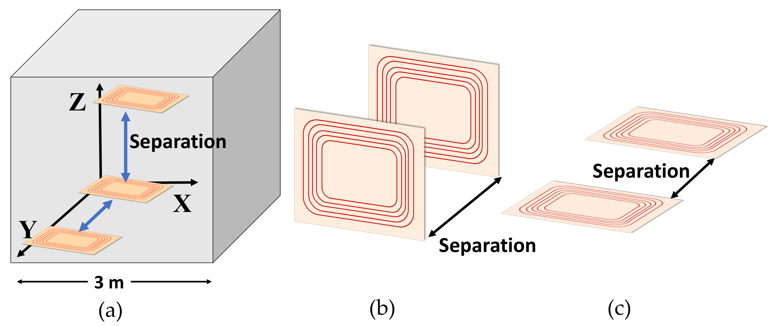
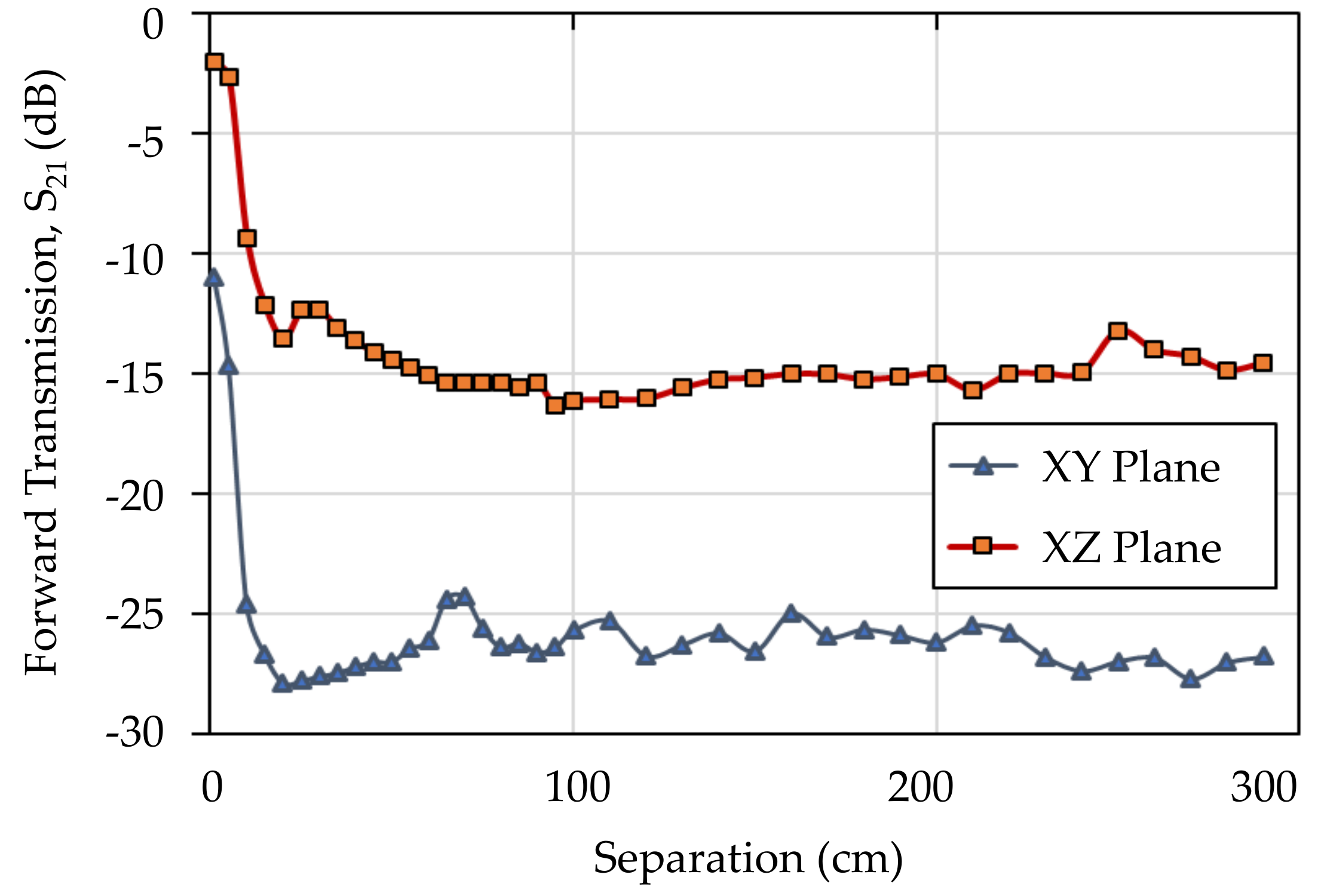
To demonstrate the separation-independent performance of the two-coil system. The separation between the coils has been studied under two conditions: fully aligned coils (on the vertical XZ plane) and full misalignment (180 misalignment, on the horizontal XY plane); demonstrating the best and worst-case scenarios respectively. Figure 12 shows the test setup of the coils and the different cases considered. The measurements have been performed on multiple 3 × 3 m planes in a 27 m volume to demonstrate the position-independence. Figure 13, the system’s S is above dB and dB when aligned and misaligned respectively.

Figure 12.
The test conditions of the proposed separation-independent WPT: (a) the 3D test volume, (b) separation between aligned coils, (c) separation between misaligned coils.

Figure 13.
Measured forward transmission between the aligned (XZ plane) and misaligned (XY plane) coils, showing no dependence on the coil separation in the uncoupled region.
While such behavior is predicted for any isotropically radiating system, the position and separation independence achieved is unmatched by any coupled or uncoupled WPT system. In addition, the magnetic field (H-field) radiated in the near-field of the transmitter coil collected more efficiently by the fully aligned receiver, explaining the 10-dB difference in the aligned and misaligned case. Nevertheless, as discussed in Section 2, due to the whole test volume’s existence in the near-field of the transmitter, propagation losses do not have an impact on the performance of the coils.
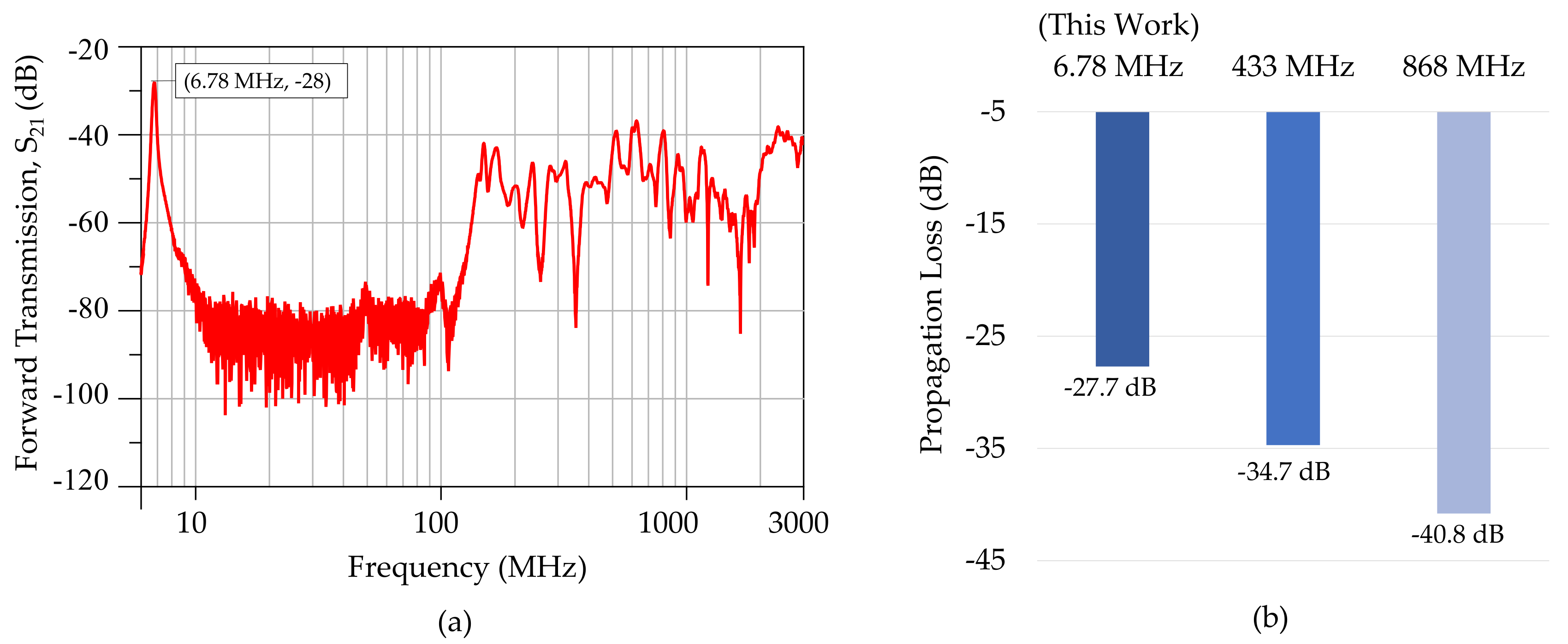
To show the advantage of the proposed approach over standard UHF radiative WPT. A broadband frequency sweep has been carried out to show the forward transmission across the full UHF spectrum, where the path loss is expected to be the limiting factor rather than the coils’ radiation efficiency. For this setup, the coils were aligned, to avoid polarization mismatch losses, and positioned at 1-m separation. Figure 14 shows that at 6.78 MHz, the forward transmission is higher by more than 10 dB compared to any of the UHF ISM-bands. While the proposed coils are not optimized for operation as UHF antennas, due to their comparable size to the wavelength they are expected to have a unity gain. Thus, the observed losses are due to the propagation losses as opposed to losses in the antenna, observed at 6.78 MHz. Both the measured results at 1-m separation (Figure 14) and the calculated frees-pace propagation losses at 433 MHz and 868 MHz at 3-m separation (Figure 14) demonstrate that the proposed uncoupled WPT technique achieves an unmatched forward transmission regardless of the coils’ separation.

Figure 14.
Comparison of the proposed near-field WPT technique with UHF ISM-bands: (a) measured S from 5 MHz up to 3 GHz at 1-m coil separation, showing the highest WPT efficiency at 6.78 MHz due to the immunity to propagation losses. (b) Comparison of the measured with the free-space losses at 433 and 868 MHz.
6. Conclusions
This work has presented a new approach to separation and position-independent WPT using a hybrid technique, combining the position-insensitivity of radiative WPT systems while overcoming the 1/d distance-effect on the path loss. Electrically small wearable antennas, using embroidered textile coils, have been fabricated and tuned for operation in the 6.78 MHz ISM-band using lumped components.
The proposed novel approach to long-range separation-independent WPT demonstrates that by selecting a low-frequency carrier for WPT the path loss term can be minimized. In addition, despite the low radiation resistance of electrically small antennas, stable wireless forward transmission can be maintained showing significant improvement over WPT based on UHF free-space propagation. The validity of the approach has been demonstrated and the efficiency of the WPT link between impedance-matched coils has been experimentally characterized. The proposed coils achieve over −17 and −28 dB forward transmission, independent of coil separation, when aligned and misaligned, respectively. Good agreement has also been observed between the simulated and measured antenna near-fields.
Using the proposed technique, wireless powering of wearable, environmental and implantable ultra-low power sensors is possible regardless of their positioning or separation from the transmitter. Future work includes investigation of different coil sizes and geometries on the measured WPT efficiency, in addition to different novel materials to improve the antenna’s radiation resistance and minimize the insertion losses. Future work also includes investigation of the coil’s wearable performance with washing, bending and operation on-body.
Author Contributions
Conceptualization, M.W., A.K. and B.Z.; Funding acquisition, B.Z.; Formal Analysis: M.W., A.K. and B.Z.; Investigation, M.W.; Writing—Original draft, M.W.; Writing—Review & editing, A.K. and B.Z. All authors have read and agreed to the published version of the manuscript.
Funding
This work was supported by the UK Engineering and Physical Sciences Research Council (EPSRC) under Grant EP/P010164/1.
Conflicts of Interest
The authors declare no conflict of interest.
References
- Weddell, A.S.; Magno, M. Energy Harvesting for Smart City Applications. In Proceedings of the 2018 International Symposium on Power Electronics, Electrical Drives, Automation and Motion (SPEEDAM), Amalfi, Italy, 20–22 June 2018. [Google Scholar]
- Ko, H.; Lee, J.; Jang, S.; Kim, J.; Pack, S. Energy Efficient Cooperative Computation Algorithm in Energy Harvesting Internet of Things. Energies 2019, 12, 4050. [Google Scholar] [CrossRef]
- He, M.; Wang, S.; Zhong, X.; Guan, M. Study of a Piezoelectric Energy Harvesting Floor Structure with Force Amplification Mechanism. Energies 2019, 12, 3516. [Google Scholar] [CrossRef]
- Xia, C.; Zhang, D.; Pedrycz, W.; Fan, K.; Guo, Y. Human Body Heat Based Thermoelectric Harvester with Ultra-Low Input Power Management System for Wireless Sensors Powering. Energies 2019, 12, 3942. [Google Scholar] [CrossRef]
- Paosangthong, W.; Wagih, M.; Torah, R.; Beeby, S. Textile-based triboelectric nanogenerator with alternating positive and negative freestanding grating structure. Nano Energy 2019, 66, 104148. [Google Scholar] [CrossRef]
- Chen, J.; Huang, Y.; Zhang, N.; Zou, H.; Liu, R.; Tao, C.; Fan, X.; Wang, Z.L. Micro-cable structured textile for simultaneously harvesting solar and mechanical energy. Nature Energy 2016, 1, 16138. [Google Scholar] [CrossRef]
- Wagih, M.; Weddell, A.S.; Beeby, S. Rectennas for RF Energy Harvesting and Wireless Power Transfer: A Review of Antenna Design. IEEE Antennas Propag. Mag. 2019. In Press. [Google Scholar]
- Wagih, M.; Weddell, A.S.; Beeby, S. Millimeter-Wave Textile Antenna for On-Body RF Energy Harvesting in Future 5G Networks. In Proceedings of the 2019 IEEE Wireless Power Transfer Conference (WPTC), London, UK, 18–21 June 2019. [Google Scholar]
- Grabham, N.J.; Li, Y.; Clare, L.R.; Stark, B.H.; Beeby, S.P. Fabrication Techniques for Manufacturing Flexible Coils on Textiles for Inductive Power Transfer. IEEE Sens. J. 2018, 18, 2599–2606. [Google Scholar] [CrossRef]
- Kang, S.H.; Jung, C.W. Textile Resonators with Thin Copper Wire for Wearable MR-WPT System. IEEE Microw. Wirel. Compon. Lett. 2017, 27, 91–93. [Google Scholar] [CrossRef]
- Komolafe, A.; Wagih, M.; Valavan, A.; Ahmed, Z.; Stuikys, A.; Zaghari, B. A smart cycling platform for textile-based sensing and wireless power transfer in smart cities. In Proceedings of the International Conference on the Challenges, Opportunities, Innovations and Applications in Electronic Textiles, London, UK, 12 November 2019. [Google Scholar]
- Sample, A.P.; Meyer, D.T.; Smith, J.R. Analysis, Experimental Results, and Range Adaptation of Magnetically Coupled Resonators for Wireless Power Transfer. IEEE Trans. Ind. Electron. 2011, 58, 544–554. [Google Scholar] [CrossRef]
- Garnica, J.; Chinga, R.A.; Lin, J. Wireless Power Transmission: From Far Field to Near Field. Proc. IEEE 2013, 101, 1321–1331. [Google Scholar] [CrossRef]
- Kang, S.H.; Nguyen, V.T.; Jung, C.W. Analysis of MR-WPT using planar textile resonators for wearable applications. IET Microw. Antennas Propag. 2016, 10, 1541–1546. [Google Scholar] [CrossRef]
- Hui, S.Y. Planar Wireless Charging Technology for Portable Electronic Products and Qi. Proc. IEEE 2013, 101, 1290–1301. [Google Scholar] [CrossRef]
- Kurs, A.; Karalis, A.; Moffatt, R.; Joannopoulos, J.D.; Fisher, P.; Soljačić, M. Wireless Power Transfer via Strongly Coupled Magnetic Resonances. Science 2007, 317, 83–86. [Google Scholar] [CrossRef] [PubMed]
- Song, C.; Huang, Y.; Zhou, J.; Zhang, J.; Yuan, S.; Carter, P. A High-Efficiency Broadband Rectenna for Ambient Wireless Energy Harvesting. IEEE Trans. Antennas Propag. 2015, 63, 3486–3495. [Google Scholar] [CrossRef]
- Muncuk, U.; Alemdar, K.; Sarode, J.D.; Chowdhury, K.R. Multiband Ambient RF Energy Harvesting Circuit Design for Enabling Batteryless Sensors and IoT. IEEE Internet Things J. 2018, 5, 2700–2714. [Google Scholar] [CrossRef]
- Tabesh, M.; Dolatsha, N.; Arbabian, A.; Niknejad, A.M. A Power-Harvesting Pad-Less Millimeter-Sized Radio. IEEE J. Solid-State Circuits 2015, 50, 962–977. [Google Scholar] [CrossRef]
- Mizojiri, S.; Shimamura, K. Wireless power transfer via Subterahertz-wave. Appl. Sci. 2015, 8, 2653. [Google Scholar] [CrossRef]
- Bao, K.; Zekios, C.L.; Georgakopoulos, S.V. A Wearable WPT System on Flexible Substrates. IEEE Antennas Wirel. Propag. Lett. 2019, 18, 931–935. [Google Scholar] [CrossRef]
- Yates, D.; Holmes, A.; Burdett, A. Optimal transmission frequency for ultralow-power short-range radio links. IEEE Trans. Circuits Syst. I Regul. Pap. 2004, 51, 1405–1413. [Google Scholar] [CrossRef]
- Seo, D.G.; Ahn, S.H.; Kim, J.H.; Lee, W.S.; Khang, S.T.; Chae, S.C.; Yu, J.W. Power transfer efficiency for distance-adaptive wireless power transfer system. In Proceedings of the 2018 International Applied Computational Electromagnetics Society Symposium (ACES), Denver, CO, USA, 25–29 March 2018. [Google Scholar]
- Imura, T.; Hori, Y. Maximizing Air Gap and Efficiency of Magnetic Resonant Coupling for Wireless Power Transfer Using Equivalent Circuit and Neumann Formula. IEEE Trans. Ind. Electron. 2011, 58, 4746–4752. [Google Scholar] [CrossRef]
- Pinuela, M.; Mitcheson, P.D.; Lucyszyn, S. Ambient RF Energy Harvesting in Urban and Semi-Urban Environments. IEEE Trans. Microw. Theory Tech. 2013, 61, 2715–2726. [Google Scholar] [CrossRef]
- Commission, F.C. Federal Communications Commission Washington, D.C 20554. Available online: https://apps.fcc.gov/edocs_public/attachmatch/DA-09-2425A1.pdf (accessed on 20 January 2020).
- Sun, H.; Geyi, W. Optimum Design of Wireless Power Transmission Systems in Unknown Electromagnetic Environments. IEEE Access 2017, 5, 2169–3536. [Google Scholar] [CrossRef]
- Austin, B.A.; Boswell, A.; Perks, M.A. Loss Mechanisms in the Electrically Small Loop Antenna [Antenna Designer’s Notebook]. IEEE Antennas Propag. Mag. 2014, 56, 142–147. [Google Scholar] [CrossRef]
- Newman, E.; Bohley, P.; Walter, C. Two methods for the measurement of antenna efficiency. IEEE Trans. Antennas Propag. 1975, 23, 457–461. [Google Scholar] [CrossRef]
- LaHaie, I. Overview of an Image-Based Technique for Predicting Far-Field Radar Cross Section from Near-Field Measurements. IEEE Antennas Propag. Mag. 2003, 45, 159–169. [Google Scholar] [CrossRef]
© 2020 by the authors. Licensee MDPI, Basel, Switzerland. This article is an open access article distributed under the terms and conditions of the Creative Commons Attribution (CC BY) license (http://creativecommons.org/licenses/by/4.0/).

