Article

The Feasibility of Replacing Coal with Biomass in Iron-Ore Pelletizing Plants with Respect to Melt-Induced Slagging

1
RISE ETC (Energy Technology Centre) AB, Box 726, S-941 28 Piteå, Sweden
2
Energy Engineering, Division of Energy Science, Luleå University of Technology, S-971 87 Luleå, Sweden
3
Luossavaara-Kiirunavaara Aktiebolag (LKAB), S-971 28 Luleå, Sweden
*
Author to whom correspondence should be addressed.
Energies 2020, 13(20), 5386; https://doi.org/10.3390/en13205386
Submission received: 11 September 2020 / Revised: 3 October 2020 / Accepted: 8 October 2020 / Published: 16 October 2020
(This article belongs to the Special Issue Thermochemical Conversion of Biomass and Waste)

Abstract

:
Combustion-generated fly ash particles in combination with the particles arising from the disintegration of iron-ore pellets, could give rise to the build-up of deposits on the refractory linings of the induration facility. Due to climate change and other environmental issues, there is a desire to cut down on use of fossil fuels. Therefore, it is of interest to investigate the feasibility of replacing coal with less carbon-intensive alternatives such as upgraded biomass, e.g., biochar and pyrolysis bio-oil. While the combustion of biomass can be carbon-neutral, the effects of biomass ash upon slagging during the iron-ore pelletizing process in a grate-kiln setup is unknown. In the present study, the effect of the interaction between the pellet dust and biomass-ash upon melt formation and the viscosity of the resulting melt, which can collectively affect melt-induced slagging, was theoretically assessed. The slagging potential of 15 different biomass fuels, suitable for the pelletizing process, was quantified and compared with one another and a reference high-rank coal using a thermodynamically derived slagging index. The replacement of coal with biomass in the pelletizing process is a cumbersome and challenging task which requires extensive and costly field measurements. Therefore, given the wide-ranging nature of the biomasses investigated in this study, a prescreening theoretical approach, such as the one employed in the present work, could narrow down the list, facilitate the choice of fuel/s, and help reduce the costs of the subsequent experimental investigations.

1. Introduction

Iron-ore pellets typically contain iron-oxides and various additional material meant to adjust the chemical composition and enhance the mechanical and metallurgic properties of the pellets. Iron-ore pellets are vital sources of iron in steelmaking. Owing to ever-increasing demands for steel, the production of iron-ore pellets has considerably expanded in recent years [1].
The pelletizing process is a combination of blending of the raw material, rolling the pellets into a ball (spheres), and a thermal treatment sintering step to harden the soft raw pellets in a kiln or on a traveling grate. During the grate-kiln process, which is the focus of the present work, the green pellets are transported along a moving grate while undergoing drying and oxidation by means of preheated gas blown from underneath the grate. After the traveling grate, the pellets enter an inclined cylindrical rotary kiln to endure sintering temperatures as high as 1250 °C and beyond [2,3,4]. At the inlet of the rotary kiln, there is a transition bend, herein referred to as the transfer-chute, connecting the grate to the rotary kiln. While the gas temperature at the transfer-chute could reach approximately 1100–1250 °C, the oxygen partial pressure typically corresponds to a highly oxidizing condition—approximately 16 vol.% as measured previously [5,6,7].
Pulverized coal is commonly used as the main fuel to maintain an adequately high process temperature required for the sintering/pelletizing process [8,9]. The combustion-generated ash material in combination with iron-ore pellet dust (from the disintegration of the pellets), can give rise to deposition/slagging. Slagging can impose unplanned stoppages to remove the deposited layer, the excessive growth of which could, in due course, disrupt the flow of pellets and gas. Moreover, severe damage and production losses may ensue [10,11,12,13,14]. Slagging/deposition can also bring about mechanical strains and refractory wear due to high-temperature corrosion [10].
During the thermal conversion process, the transformation of ash-forming matter may involve the formation of molten ash particles that can coalesce into a chunk of agglomerated mass and lead to the build-up of slags on the refractory linings. Ash transformation phenomena during pulverized-coal combustion have been extensively studied (see [15,16,17,18,19]). However, a better understanding of such phenomena associated with the iron-ore pelletizing process is still required.
In our previous publications [6,7], the effect of the interaction between the pellet dust and coal-ash particles upon deposition/slagging was outlined as follows: (1) increased melt formation, which aggravated slagging/deposition, (2) intensified slagging/deposition due to a reduction in viscosity which was caused by the incorporation of Fe (from the pellet dust) into the aluminosilicate melt (originating from the coal-ash). Hence, the severity of slagging/deposition was surmised to have depended on the composition of the ash-deposit as well as significant factors such as temperature and viscosity. Accordingly, the next study particularly focused on the effect of ash composition upon the slagging tendency of high-rank coals with different ash compositions [20]. A qualitative slagging indicator (QSI) was proposed and validated experimentally. The QSI was intended to pre-screen new/alternative coals with respect to their slagging potential. The proposed QSI suggests the following: (1) there is an inverse relationship between the slagging tendency and the viscosity of the molten ash, (2) as viscosity decreases, stronger deposits are bound to form, and the deposition tendency increases. It was also deduced that low-viscosity molten phases, characterized by the presence of certain fluxing agents (e.g., K2O, CaO, Na2O, MgO, and Fe2O3), facilitated deposition.
In our most recent study, the impact of co-firing high-rank coal and woody biomass (share of biomass: maximum 30% by energy) upon the slagging tendency in the grate-kiln process was assessed [21]. Deposition rates were experimentally obtained in an attempt to investigate the relationship between the deposition tendency, molten fractions, and viscosity. An equation relating the absolute deposition tendency (ADT) to thermodynamically derived variables (such as melt fraction and viscosity) was proposed [21].
Due to climate change and other pollution concerns, there is a desire to cut down on use of fossil fuels. In a pilot-scale study, Wiinikka et al. [22] studied the viability of substituting coal and fuel oil with renewable alternatives. The results indicated that it would be difficult to completely replace fossil fuels with solid biomass while entirely avoid the resulting escalated ash-induced complications. While the combustion of biomass can be CO2-neutral, the extent of slagging-related complications associated with biomass firing in iron-ore pelletizing remains unknown. When biomass ash is present, it is likely that the pellet dust and biomass ash will interact through which the melting properties of the resulting mixture can change, thereby affecting the degree of slagging. The above-mentioned interaction can be different for biomass ash compared to coal ash due to their innate difference in ash chemistry [23,24,25]. Therefore, in the present study, the effect of the interaction between pellet dust and biomass-ash upon melt formation and the viscosity of the resulting melt, both of which can collectively affect melt-induced slagging, was theoretically assessed. Five biomass fuels with different ash compositions, which were deemed potential candidates to replace coal in the pelletizing process, together with their corresponding products (biochar and bio-oil) from the fast pyrolysis of the raw feedstock, were considered for the present work. The choice of the upgraded fuels (the pyrolysis products) is because both biochar and bio-oil have a higher energy density compared to the raw biomass, and both are preferable to the raw fuels with regard to storage and transportation. However, between the upgraded fuels, biochar has a higher ash content than the raw biomass.
The qualitative slagging indicator (QSI) and the ADT (absolute deposition tendency) developed in our recent studies [20,21] were used to propose a slagging index applicable to mono-combustion of biomass in iron-ore pelletizing. Subsequently, the slagging potential of the 15 renewable candidates was quantified and compared with one another and a reference high-rank coal.

2. Materials and Methods

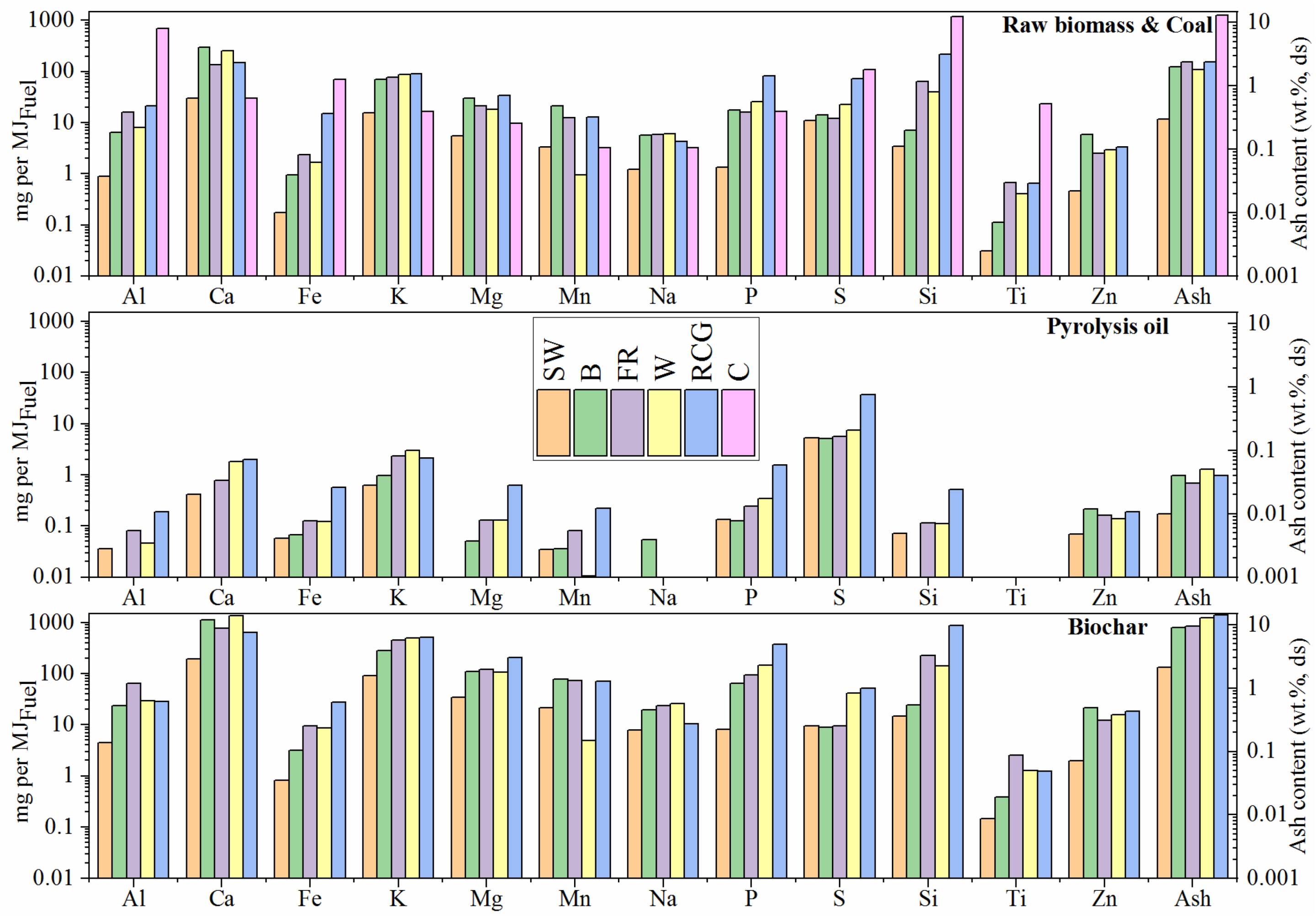
2.1. Proximate, Ultimate, and Calorimetric Analysis of the Investigated Fuels

Five different Nordic biomass fuels were investigated in this study, namely stem wood, willow, reed canary grass, bark, and forest residues. The stem wood is composed of sawdust of Swedish pine and spruce originating from the wood pellets provided by Stenvalls trä AB, Sweden. The willow is from Salix Energy Europa AB (Sweden), which originates from the willow of the species Tora (Salix Schwerinii and Salix Viminalis). The reed canary grass is from Glommers Miljöenergi AB (Sweden). The bark and forest residues were both delivered by Smurfit Kappa Kraftliner (Sweden). The bark is a combination of pine, spruce, and birch bark (approximately one-third of each, by weight). The forest residues contain approximately 67, 30, and 3 wt.% residues of pine, spruce, and birch. The pyrolysis products, i.e., the pyrolysis oil (PO) and biochar, were produced from the above-mentioned fuels in a pilot-scale pyrolysis facility (described in detail by Wiinikka et al. [26]).
A reference high-rank coal, as well as a typical pellet dust sample, were also used in this study. A detailed chemical analysis of the coal, pellet dust, the raw biomasses, and their respective pyrolysis products, i.e., the PO and biochar, is presented in the Supplementary Materials (Section A, Tables S1–S4) along with the calorimetric analysis of the fuels. However, the mass distribution of the inorganic elements (per MJ of the dry fuel) is given in Figure 1. The biomass fuels investigated in this study have all been characterized in more detail elsewhere [27,28]. The properties of the pyrolysis products are different from the corresponding raw biomass with respect to the elemental composition, water, and ash content (see Section A, Tables S1–S3 in the Supplementary Materials). The heating values (dry substance) are similar for the PO and biomass and higher for the biochar because of the differences in the elemental composition. H/C and O/C ratios of the biochar are lower than those of the raw biomasses and PO, which are comparatively similar. The PO has a higher water content than the raw biomass due to the co-condensation of the gaseous pyrolysis products and the water formed through gas-phase reactions during the pyrolysis process. Most of the ash originally found in the raw biomass is retained in the biochar because most of the ash forming elements tend to stay in the condensed phases (minimal evaporation) under the pyrolizer conditions.

2.2. Thermochemical Equilibrium Calculations (TECs) and Viscosity Estimations

Slag formation and the build-up of tenacious deposits can be mostly attributed to the formation of molten ash [24]. Using thermochemical equilibrium calculations (TECs), one can determine the conditions under which molten or partially molten multicomponent phases are thermodynamically stable. Hence, TECs can help determine the conditions under which the slagging propensity may be improved or exacerbated. The foregoing is particularly helpful when coupled with viscosity estimations made based on the predicted molten phases. The applicability of TECs in making reliable predictions concerning deposition/slagging has been experimentally verified in the authors’ previous studies [6,7,20,29]. Thermochemical equilibrium calculations were extensively used by others pertaining to other technologies, e.g., biomass gasification [30,31,32,33].
The TECs of the present study were applied to the regions of interest, namely the transfer-chute and rotary kiln, as indicated in Figure 2a. The TECs were carried out under the oxidizing conditions prevailing in grate-kilns and within the typical temperature range of the transfer-chute and the rotary-kiln, i.e., 1050–1250 and 1200–1350 °C, respectively. The transfer-chute is allegedly one of the most challenging areas of the grate-kiln setup with regard to slagging/deposition [11,12,20,34], and the rotary kiln itself is prone to ring formation, which is reportedly a major complication in iron-ore pelletizing [10,35]. Figure 2b illustrates an expected ash transformation scheme associated with biomass combustion in suspension firing, which also encompasses presumed interactions between biomass ash and pellet dust particles. During pulverized-fuel combustion, as in rotary grate-kilns, calcium is expected to be dispersed as small micron-sized CaO particles. Potassium, on the other hand, is most likely released as gas either as monatomic K (g) or as KOH (g), with the latter being the most stable potassium-containing gas species released under combustion atmospheres [36]. Dependent upon the kinematic behavior of the above-mentioned species inherent to the grate-kiln process, slagging/deposition may occur inside the induration machine. The Ca-rich biomass-ash can meet the disintegrated iron-ore pellet dust while a gaseous alkali-laden atmosphere (predominately K-species) surrounding the ash particles can contribute to melt formation [31]. These interactions are schematically depicted in Figure 2b, while Figure 2c,d demonstrates the problematic slagging/deposition at the inlet of the kiln (transfer-chute) and near the burner (beginning of the kiln), respectively.
In this study, the GTOX thermodynamic database [37] was employed, which contains molten oxide solutions as well as solid solutions codeveloped by GTT-Technologies and IEK2-Forschungszentrum Jülich GmbH. Thermodynamic data associated with the gases and pure stoichiometric compounds were extracted from both GTOX and FactSage [38,39]. Moreover, Chemsheet [40] was also employed to facilitate the extensive computations performed in this study and predict the formation of the coexisting phases based on the minimization of Gibbs energy.
The gas-phase was regarded as an ideal gas (perfect mixture), and the following gaseous species were considered: CO2, N2, O2, H2O, K, and KOH. The viscosity of the molten fraction of the predicted phases was estimated using the associate-based model previously established by Nentwig et al. [41] and Wu et al. [42,43,44,45,46]. The experimentally derived viscosity models reported in the literature [47,48,49] are restricted to a specific range of compositions and atmospheres. Moreover, the empirical models are inept to explicitly represent thermodynamic equilibrium considerations, which are the mainstay of ash transformation studies. On the contrary, the viscosity model used in the current work involves a broad range of chemical compositions and takes thermodynamic equilibrium into account. Comprehensive descriptions of the employed databases/models can be found elsewhere [41,42,43,44,50,51,52,53,54,55]. The model predictions associated with the higher-order systems (such as the one in the present work) are, in general, within the experimental uncertainty [43,44,45], hence considered adequate in the prediction of the variation trends that are sought after in this study. As mentioned earlier, a high-rank coal was used in the TECs as a reference to compare the predicted slagging tendencies of the biomasses in the presence of pellet dust. The pellet dust was sampled in a full-scale grate-kiln facility, and the complete oxidation of magnetite to hematite was confirmed. The chemical composition of the pellet dust (see Table S4 of Section A in the Supplementary Materials) coupled with X-ray diffraction (XRD) verified that approximately 97 wt.% of the pellet dust contained hematite (Fe2O3) among other minor crystalline phases. The chemical composition of the fuels and pellet dust (see Section A, Tables S1–S4 in the Supplementary Materials) was used as input in the TECs of the present study. A comprehensive description of the predicted condensed phases is shown in Table S5 of Section A in the Supplementary Materials.

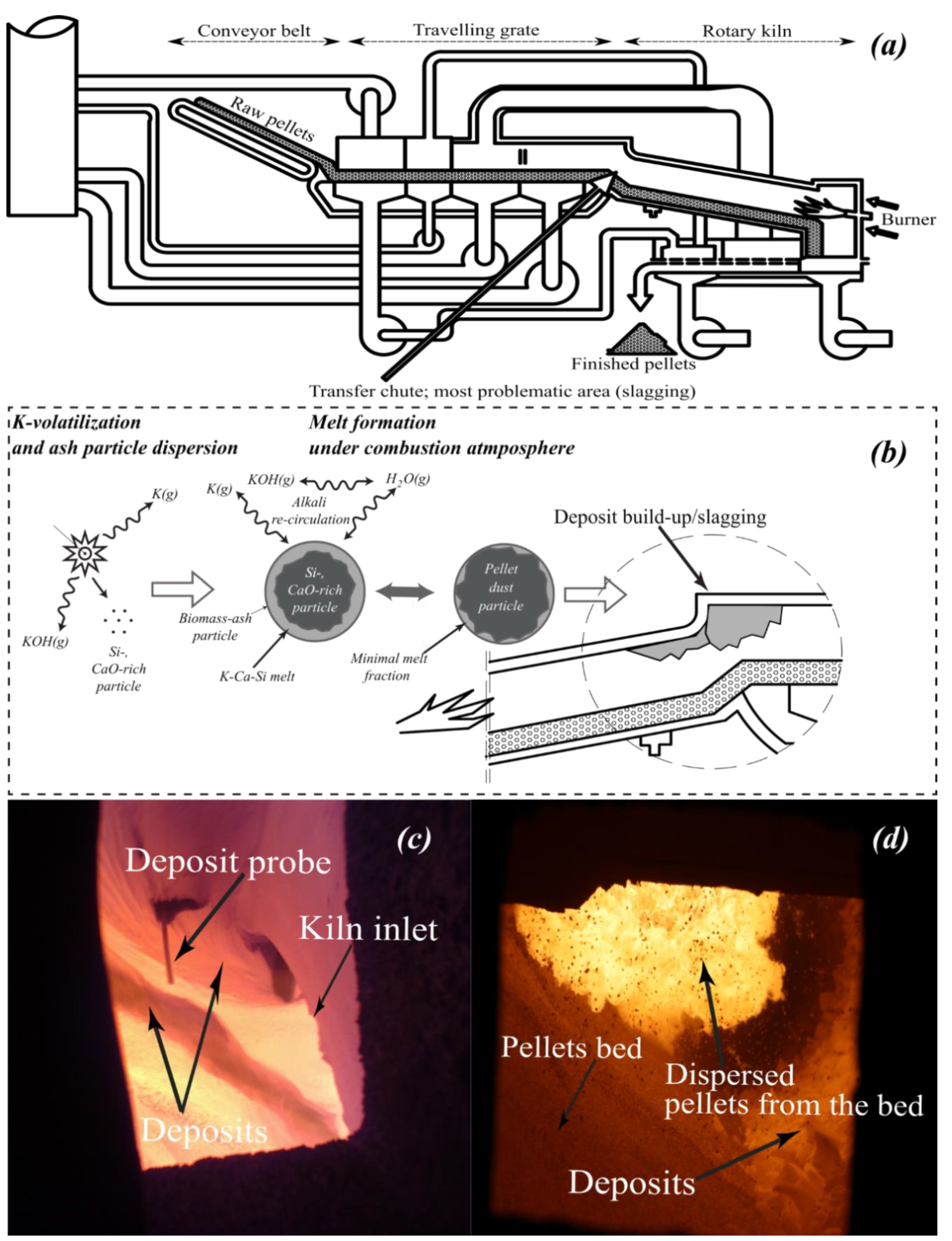
2.3. The Previously Introduced Qualitative Slagging Indicator and the Slagging/Deposition Tendency

The qualitative slagging indictor (QSI) previously proposed in our recent study [20] was employed as one of the comparison tools to compare the slagging propensities of the biomasses in the presence of pellet dust.
The calculated QSI values were found to have a positive correlation with the experimentally obtained slagging/deposition rates (see Figure 15 in [20]), where QSI is given by Equation (1), and µ is the viscosity (Pa.s) of the molten fraction of the predicted condensed phases. The slagging/deposition tendency was defined as the formation of molten ash particles (molten slag) that can accumulate on surfaces upon impaction. It was determined as the mass of the deposited particles (adhered to the sampling probe) divided by the total amount of ash flow in the furnace [g/kg ash input]. The above-mentioned normalization indicates that the deposition tendency is governed by the ash composition regardless of the ash content. In our previous study [20], the QSI was found to have a positive correlation with the normalized slagging/deposition tendency [g/kg ash input]. The temperature dependence of QSI was elaborated on in our previous publications [20,21].
Q S I   = ln ( 1 μ )

2.4. The Absolute Slagging/Deposition Tendency (ADT)

As mentioned earlier, the absolute slagging/deposition tendency was previously defined by the authors elsewhere [21]. In contrast to the normalized deposition rate (g/kg ash input/h), described in Section 2.3, that merely indicates the significance of ash composition (ash chemistry), the absolute deposition tendency, ADT(g/h), apart from the importance of the ash composition, signifies the potential impact of ash flow (kg ash input/h) on slagging/deposition as well. Clearly, the ash flow (kg ash input/h) is directly dependent on the ash content. A relationship between the absolute deposition tendency, molten fraction, and viscosity was previously suggested as follows:
A D T   ~   log ( k g   m o l t e n   a s h h r × 1 v i s c o s i t y ( P a . s ) )
Equation (2) was verified by the previously conducted experiments [20]. A detailed description of Equation (2) can be found in our previous publication [21]. The observed relationship (Equation (2)) suggests that the higher the molten fraction of the bulk ash flow and the lower the viscosity, the higher the particle sticking likelihood, which can together intensify slagging/deposition. In the present study, the total amount of raw/char/bio-oil needed to reach a thermal output of 40 MW was calculated for each fuel given their LHV (as received). Subsequently, the total amount of ash flow per hour was calculated from the ash content, and the above-mentioned amount of fed raw/char/bio-oil. The kg molten ash per hour was calculated as the product of the predicted melt fraction and the total amount of ash flow in the kiln.

3. Results and Discussion

A comprehensive assemblage of the entire results/figures corresponding to each case can be found in the Supplementary Materials (Sections B–E). The following paragraph outlines the general assumptions made:
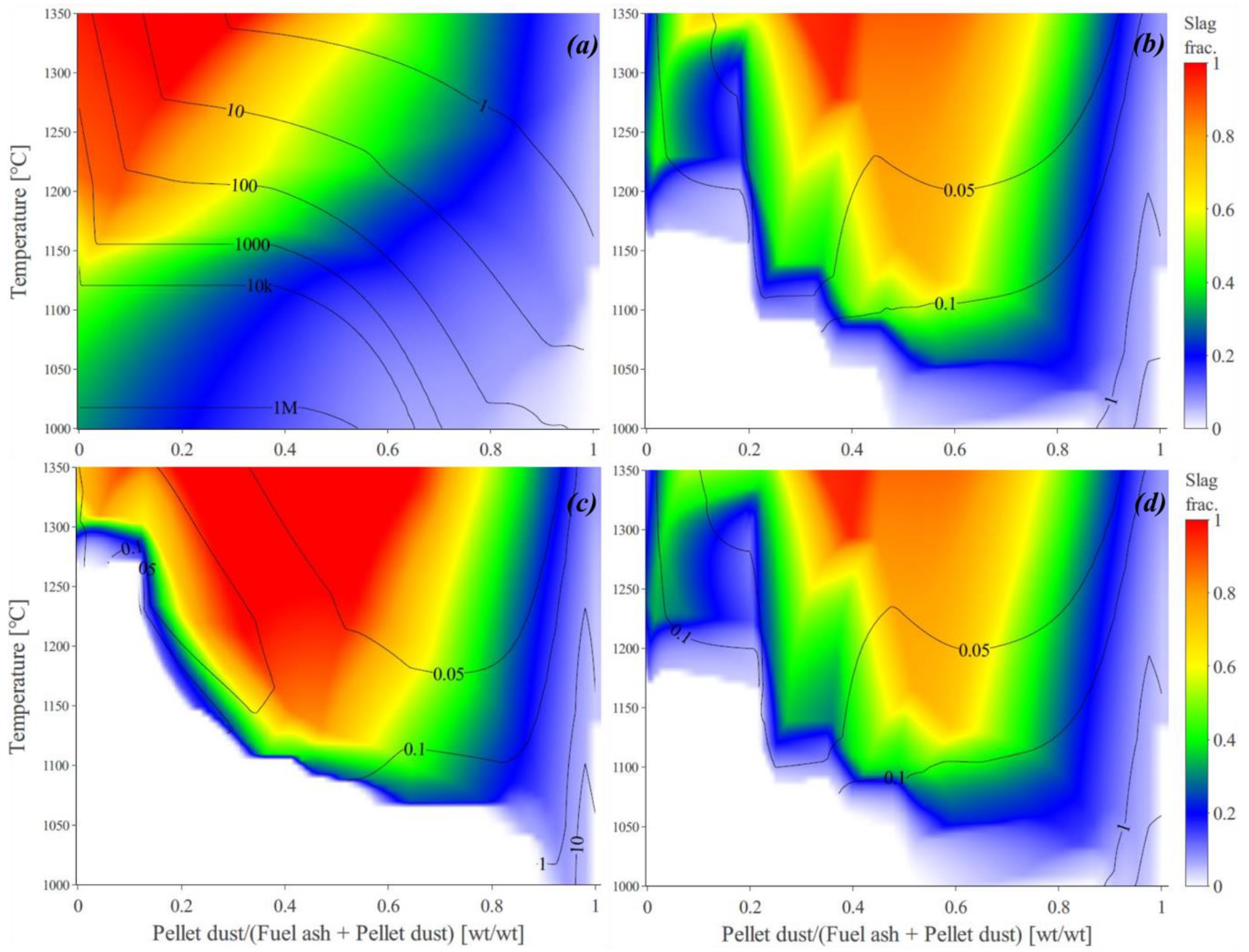
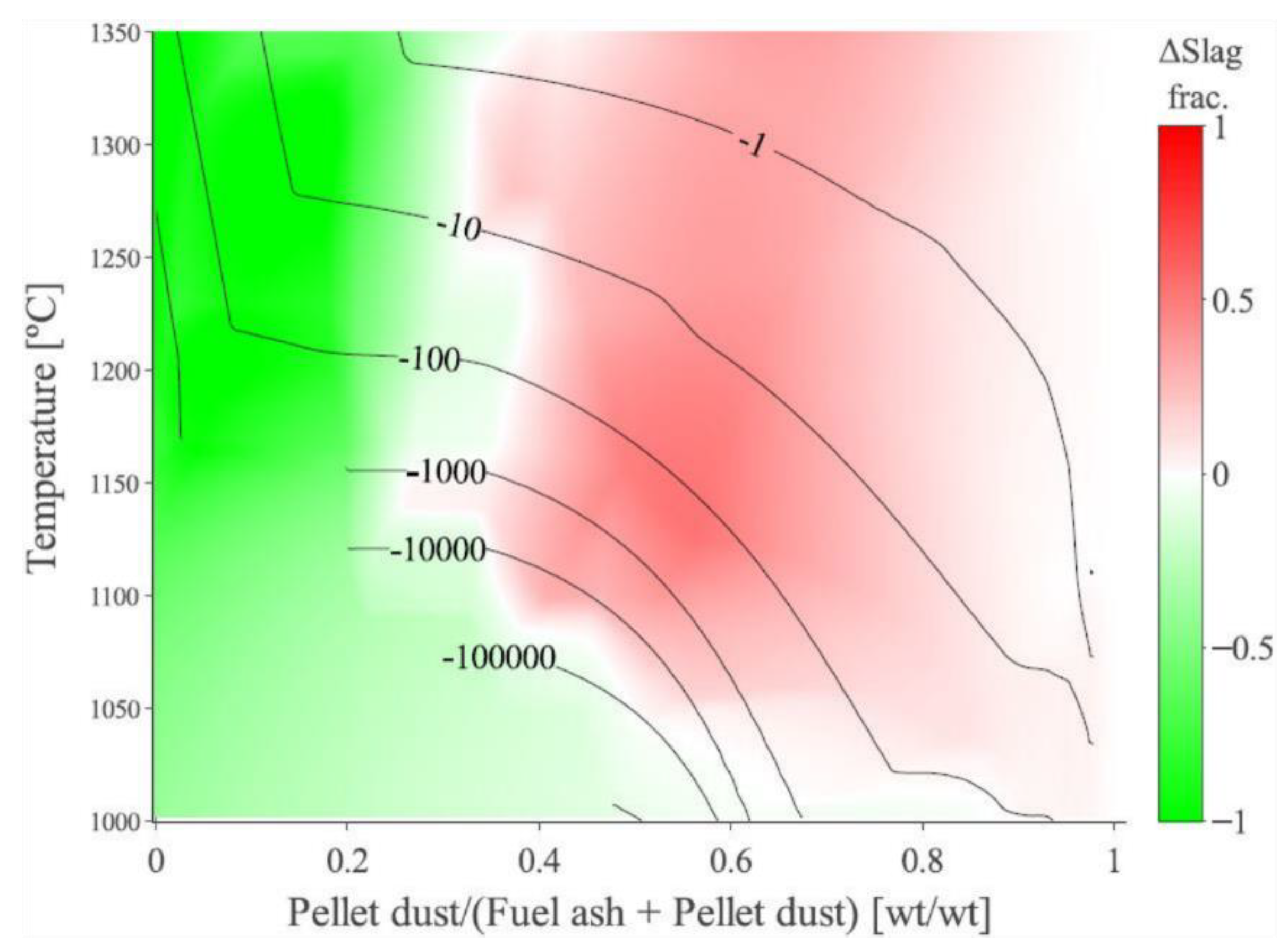
  • Interaction of iron-ore pellet dust and fuel ash: from 0 to 100 wt.% share. Due to the uncertainty regarding the extent of interaction, the amount of ash particles that can potentially interact with the pellet dust can differ from the ratio of their corresponding bulk flows, hence the necessity to study the entire range from 0 to 100 wt.% share of pellet dust (X-axis in the plots).
  • Oxidizing gaseous atmosphere at 1 atm, where the partial pressure of oxygen was 16 vol.% (equivalent to an air factor of approximately 4.5), saturated H2O (g) was used, and N2 was used as balance.
  • The temperature range studied was from 1000 to 1500 °C. However, according to the previously conducted temperature measurements at the transfer-chute [10,11,12,13], only the results corresponding to the temperatures up to 1350 °C are presented in Section 3.1, Section 3.2 and Section 3.3. However, in Section 3.4 the calculations that are taken into consideration cover the entire studied temperature range (1000–1500 °C).

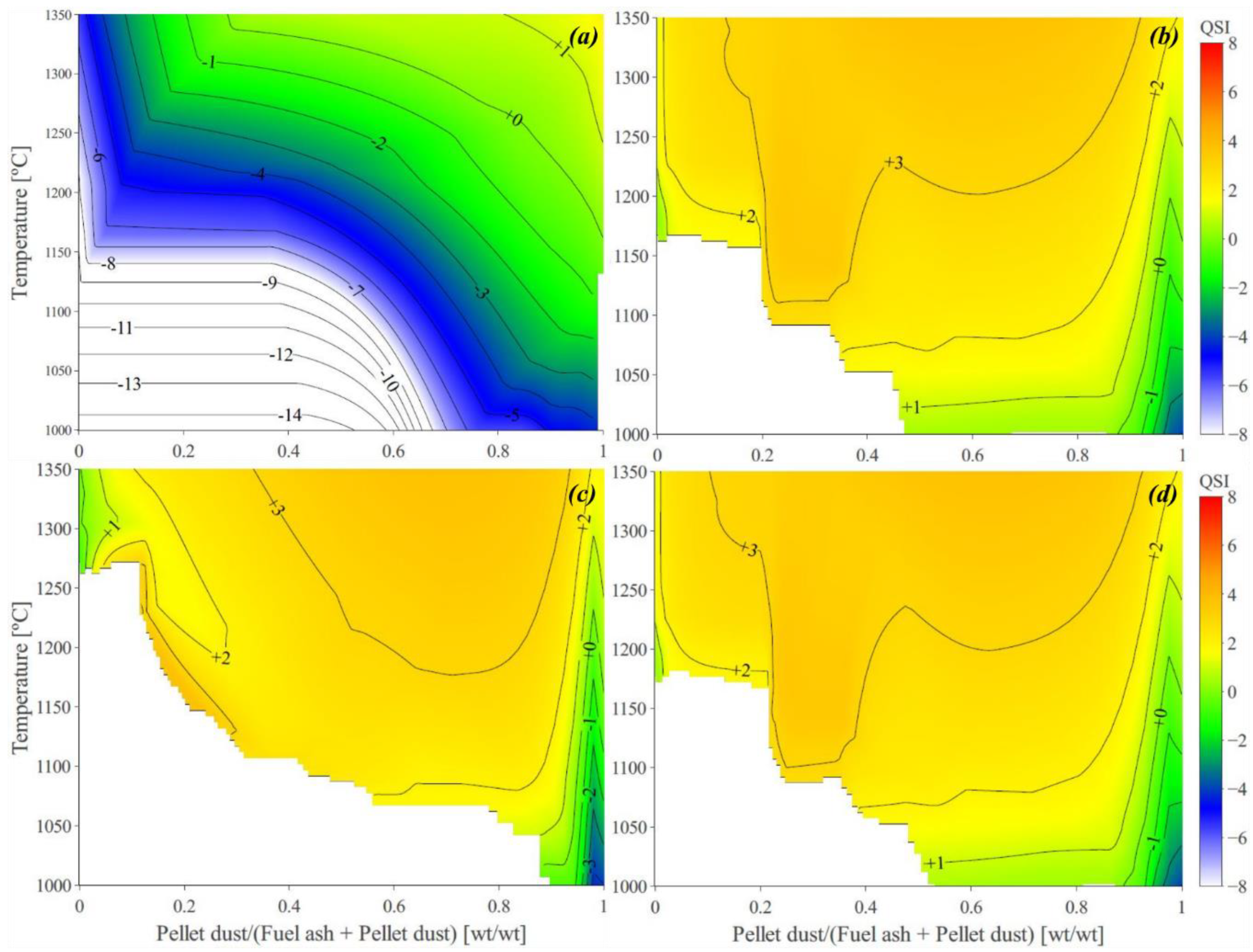
3.1. Predicted Melt Fraction, Viscosity Estimations, and the Calculated QSIs

Note that in all the upcoming plots, the X-axis represents the share of pellet dust in the deposits and ranges from 0 when there is no pellet dust to 1 when pellet dust is burned in an ash-free medium (such as the natural gas). Only the TECs associated with the reference coal, raw stem wood, stem wood-pyrolysis oil, and stem wood-biochar are presented here (see Sections B–D in the Supplementary Materials for the rest of the investigated fuels).
Figure 3 illustrates the predicted melt fractions (i.e., the predicted mass of the molten phase divided by the total mass of the condensed phases) and the estimated viscosities of the corresponding molten phases for the reference coal (RC), raw stem wood, stem wood-pyrolysis oil, and stem wood-biochar when temperature varies from 1000 to 1350 °C. The contour lines represent the viscosity of the melt in Pa.s.
Irrespective of the fuel, viscosity tends to decrease with increasing temperature and increasing pellet dust share. Melt (slag) fractions demonstrate more variation but, in general, decrease when the share of pellet dust increases. However, from these figures, the difference between the fuels is not readily discernable since the plots look similar mostly because the ash composition of the fuels is, to a reasonable extent, similar. Therefore, the differences in melt fractions were also calculated for these fuels (only the difference between the coal and raw stem wood is presented here; see Sections B–D in the Supplementary Materials for the rest of the fuels) under the following definition:
Δ(slag frac.) = (slag frac.)stem wood − (slag frac.)ref, where (slag frac.)stem wood and (slag frac.)ref are the mass fractions of the predicted melt for the raw stem wood and the RC case (coal), respectively. The plot for Δ(slag frac.), which shows the difference in the amount of melt formation between the two fuels, is presented in Figure 4. Considering the definition of the Δ(slag frac.) mentioned above, the melt fractions predicted for the raw stem wood are less than the RC case if Δ(slag frac.) < 0 (indicated by green), and higher if Δ(slag frac.) > 0 (indicated by red). Therefore, according Figure 4 the amount of melt formation for the raw stem wood is predicted to be higher when the share of pellet dust is above approximately 50 wt.%. However, when the share of pellet dust is low, the raw stem wood is predicted to have a lower melt fraction compared to the reference coal, the reason for which is discussed later.
However, the findings presented in our recent publications [20,21] indicated that the estimated viscosities (QSI), exhibited a more credible correlation with deposition rates [g/kg ash input] compared to the melt fraction. Accordingly, the viscosities calculated for the investigated fuels (see Section 2.3) produce the QSI plots demonstrated in Figure 5. However, from these figures, the difference between the fuels is not readily discernable. Therefore, the differences in QSI were also calculated for these fuels (only the difference between the coal and raw stem wood is presented here; see Sections B–D in the Supplementary Materials for the rest of the fuels) under the following definition:
Δ(QSI) = (QSI)stem wood − (QSI)ref, where (QSI)stem wood and (QSI.)ref are the calculated QSIs for the raw stem wood and the RC case (coal), respectively. The plot for Δ(QSI), which shows the difference in the slagging tendency [g/kg ash input] between the two fuels, is presented in Figure 6. Considering the definition of the Δ(QSI), the QSI or slagging tendency for the raw stem wood is less than the RC case if Δ(QSI.) < 0 (indicated by green), and higher if Δ(QSI) > 0 (indicated by red). Therefore, according to Figure 6, for the majority of the temperature ranges and pellet-dust share, the slagging tendency is higher when the raw stem wood is combusted in the induration machine. Since QSI is defined as the reciprocal of viscosity, therefore, the viscosity of the melt formed during the combustion of the raw stem wood is lower than that during the combustion of coal. Therefore, stronger deposits are expected to build up associated with the combustion of the raw stem wood.
The predicted melt fractions, viscosity estimations, and the calculated QSIs for the rest of the biomasses (raw/bio-oil/biochar) are given in the Supplementary Materials (Sections B–D). The plots of Δ(slag frac.) and Δ(QSI) for the rest of the biomasses (raw/bio-oil/biochar), when compared to the reference coal, are also presented in the Supplementary Materials (Sections B–D). Generally, the Δ(slag frac.) plots, taking the coal as reference (for all biomasses) follow a similar trend as those presented in the present study. The foregoing suggests that the amount of melt formation for the biomasses (raw/bio-oil/biochar) is predicted to be higher than that of the coal when the share of pellet dust is above nearly 50 wt.%. However, when the share of pellet dust is low, all the investigated biomasses (raw/bio-oil/biochar) are predicted to have a lower melt fraction compared to the reference coal, the reason for which is discussed later (Section 3.4 and Section 3.5).
According to Δ(QSI) plots presented in the Supplementary Materials (Sections B–D), for all temperature ranges and pellet-dust share, the slagging tendency [g/kg ash input] is higher when the biomasses (raw/bio-oil/biochar) are combusted in the induration machine. Therefore, the viscosity of the melt formed during the combustion of the biomasses is lower than that during the combustion of the reference coal. Therefore, stronger deposits are expected to build up associated with the combustion of the biomasses (raw/bio-oil/biochar).
Note that QSI indicates the slagging/deposition tendency notwithstanding the ash content i.e., [g/kg ash input], implying that the QSI is not of practical value to rightfully compare the slagging tendencies since it disregards the ash content. Therefore, it is encouraged to use QSI when the ash contents of the fuels to be compared are in the same order of magnitude, for instance, when high-rank coals are compared with each other. However, when it comes to biomass the ash content is considerably lower than that of high-rank coals. Therefore, the QSI is a good measure to compare the slagging tendency [g/kg ash input] and a good measure to compare the strength of the resulting deposits (since it is the reciprocal of viscosity). However, for the absolute deposition tendency [g/h], which is of higher practical value, the ADT (Equation (2)) is a better comparison tool.
The Δ(slag frac.) and Δ(QSI), which help compare the biomasses with each other, are also given in the Supplementary Materials (Sections B–D). Note that to make a comparison between the biomasses in each category (raw/bio-oil/biochar), the stem wood was taken as the reference, arbitrarily (see Sections B–D in the Supplementary Materials).

3.2. The Predicted Absolute Slagging/Deposition Tendency (ADT)

The plots of ADTs (Equation (2)) for all the investigated fuels are given in the Supplementary Materials (Sections B–D).
The differences in ADTs were also calculated for all the investigated fuels once taking coal as the reference and once taking stem wood in each biomass category (raw/bio-oil/biochar) as the reference. The Δ(ADT) plots are presented in the Supplementary Materials (Sections B–D). However, as an illustration, the Δ(ADT) plot for coal vs. raw stem wood is presented here under the following definition:
Δ(ADT) = (ADT)stem wood − (ADT)ref, where (ADT)stem wood and (ADT)ref are the calculated QSIs for the raw stem wood and the RC case (coal), respectively. The plot for Δ(ADT), which shows the difference in the slagging tendency [g/h] between the two fuels, is presented in Figure 6. Considering the definition of the Δ(ADT), the ADT or absolute slagging tendency for the raw stem wood is less than the RC case if Δ(ADT) < 0 (indicated by green), and higher if Δ(ADT) > 0 (indicated by red). Therefore, according to Figure 7 for all temperature ranges and pellet-dust share, the absolute slagging tendency [g/h] is predicted to be higher when the raw stem wood is combusted in the induration machine.
According to the Δ(ADT) plots presented in the Supplementary Materials (Sections B–D), the above-mentioned supposition applies to all biomasses when compared to the reference coal.

3.3. The Effect of Ash Composition on Slagging/Deposition

To understand the effects that ash composition may have upon the slagging/deposition propensity, the melt components (present in the predicted molten phase) were categorized into basic and acidic, otherwise known as “network modifiers” and “network formers”.
Deemed as cations occupying sites in the oxide melt, network formers assume tetrahedral coordination with the oxygen atoms. Hence, they are regarded as building blocks within the network. Network modifiers, on the other hand, demonstrate a disruptive effect on the network [56,57,58,59].
The following equation (Equation (3)) was defined as the share of “network modifiers” to “network formers”:
B A = N e t w o r k   m o d i f i e r s N e t w o r k   f o r m e r s = C a O + M g O + K 2 O + N a 2 O + F e 2 O 3 + F e O S i O 2 + A l 2 O 3  
where SiO2, etc., represent the mole fractions predicted as the main components of the melt. A detailed discussion on the ratio between network modifiers and network formers can be found in Sefidari et al. [20], where a positive correlation was observed between Equation (3), the QSI, and the experimentally attained deposition rates. In other words, higher network former/modifier ratios correspond to higher deposition rates. It should also be noted that high values of this ratio mainly imply that the melt of interest is mostly composed of fluxing agents (basic components) instead of acidic components.
Furthermore, this value could be utilized as a criterion in investigating and comparing the basicity or acidity of the melt between the fuels. Therefore, the differences in B/A ratios were calculated for all the investigated fuels with coal and stem wood in each biomass category (raw/bio-oil/biochar) being interchangeably taken as the references. The Δ(B/A) plots are comprehensively presented in the Supplementary Materials (Sections B–D). However, for the purpose of illustration, the Δ(B/A) plot for coal vs. raw stem wood is presented here under the following definition:
Δ(B/A) = (B/A)stem wood − (B/A)ref, where (B/A)stem wood and (B/A)ref are the B/A ratios calculated for the raw stem wood and the RC case (coal), respectively. The plot for Δ(B/A), which shows the difference in the level of basicity/acidity of the produced melt, is presented in Figure 8. The molten phase for the raw stem wood is less basic than coal when Δ(B/A) < 0 (indicated by green), and more basic when Δ(QSI) > 0 (indicated by red).
The results indicate that (Figure 8), in contrast to coal, under most conditions, the raw stem wood is predicted to have a higher share of network modifiers (fluxing agents) in the melt. The foregoing suggests that the resulting melt (owing to the interaction of fuel ash and pellet dust) has a lower viscosity in the case of the raw stem wood compared to coal. The presence of low viscosity molten slags in rotary-kilns (as verified in the previous publications [6,7]) results in the formation of sturdier deposits, which ultimately complicates the cleaning procedures intended to remove the deposited ash.
As can be readily inferred, QSI, ADT, and B/A could help compare the slagging tendency expected from the fuels. The QSI and ADT represent an estimation of viscosity while taking thermodynamic considerations into account, whereas, the B/A ratio is merely a ratio that disregards thermodynamics. Nevertheless, the overall agreement in the predicted trends (Figure 6 vs. Figure 8) suggests that the B/A ratio has a positive correlation with QSI and ADT, thus negatively correlated with viscosity.
Given the statement made above, the higher slagging/deposition tendency predicted for the raw stem wood (when compared to the coal) can be attributed to the higher amounts of fluxing agents predicted in the melt fraction of its ash (or higher B/A values for the raw stem wood).

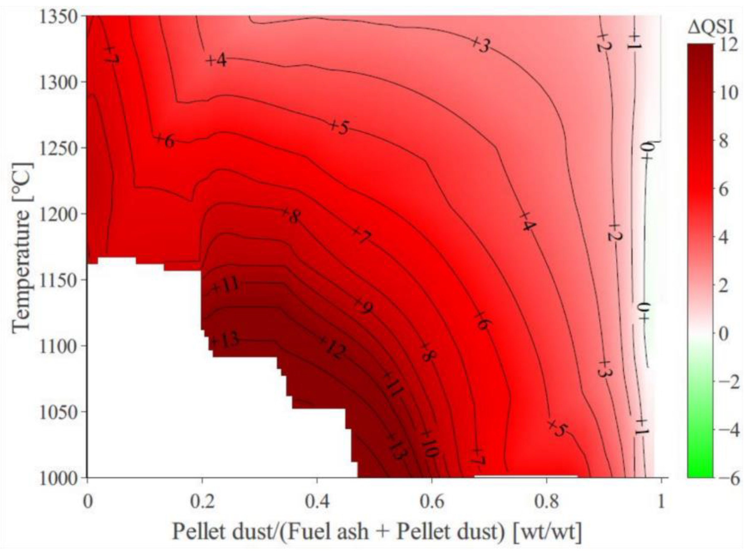
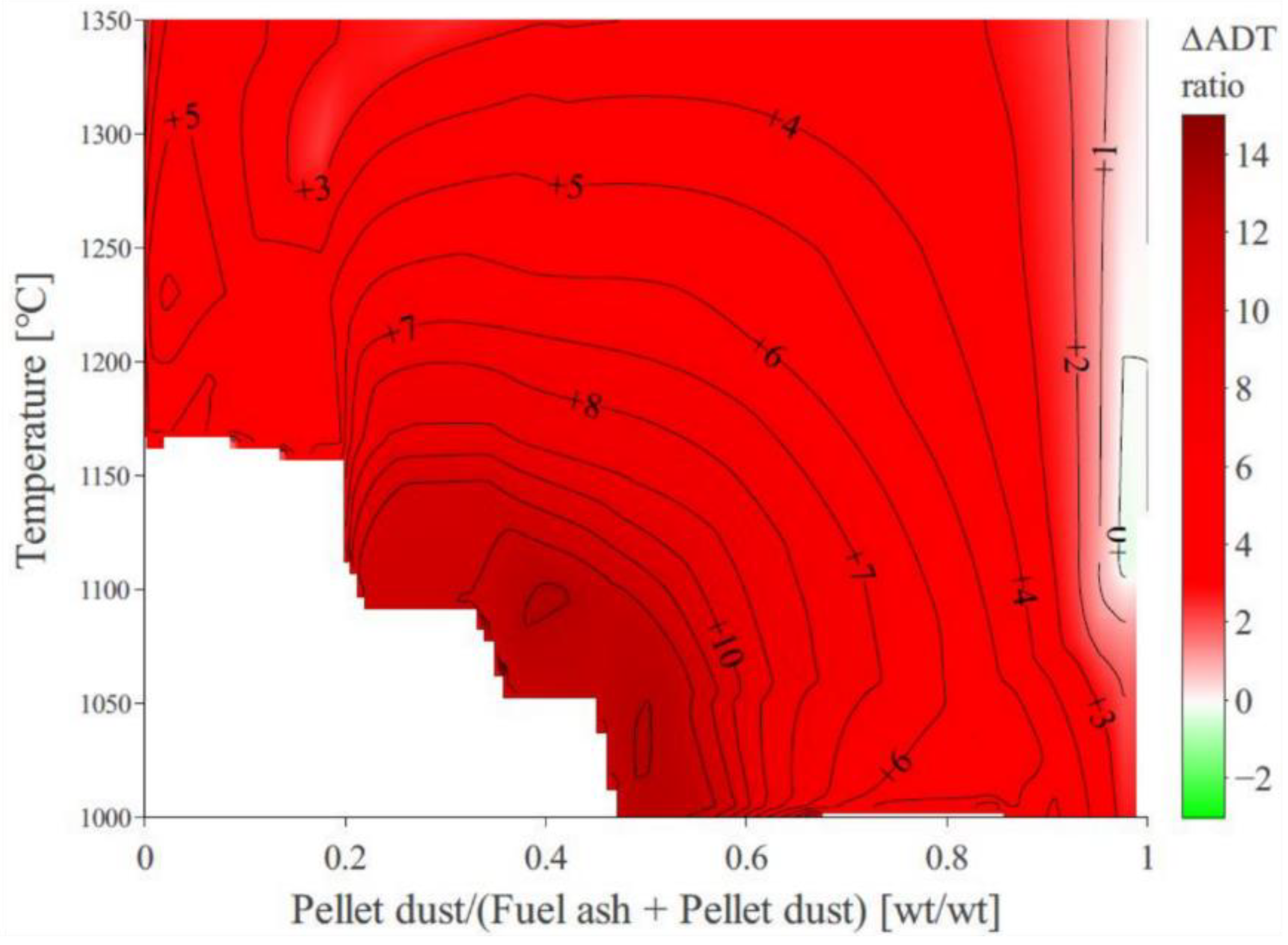
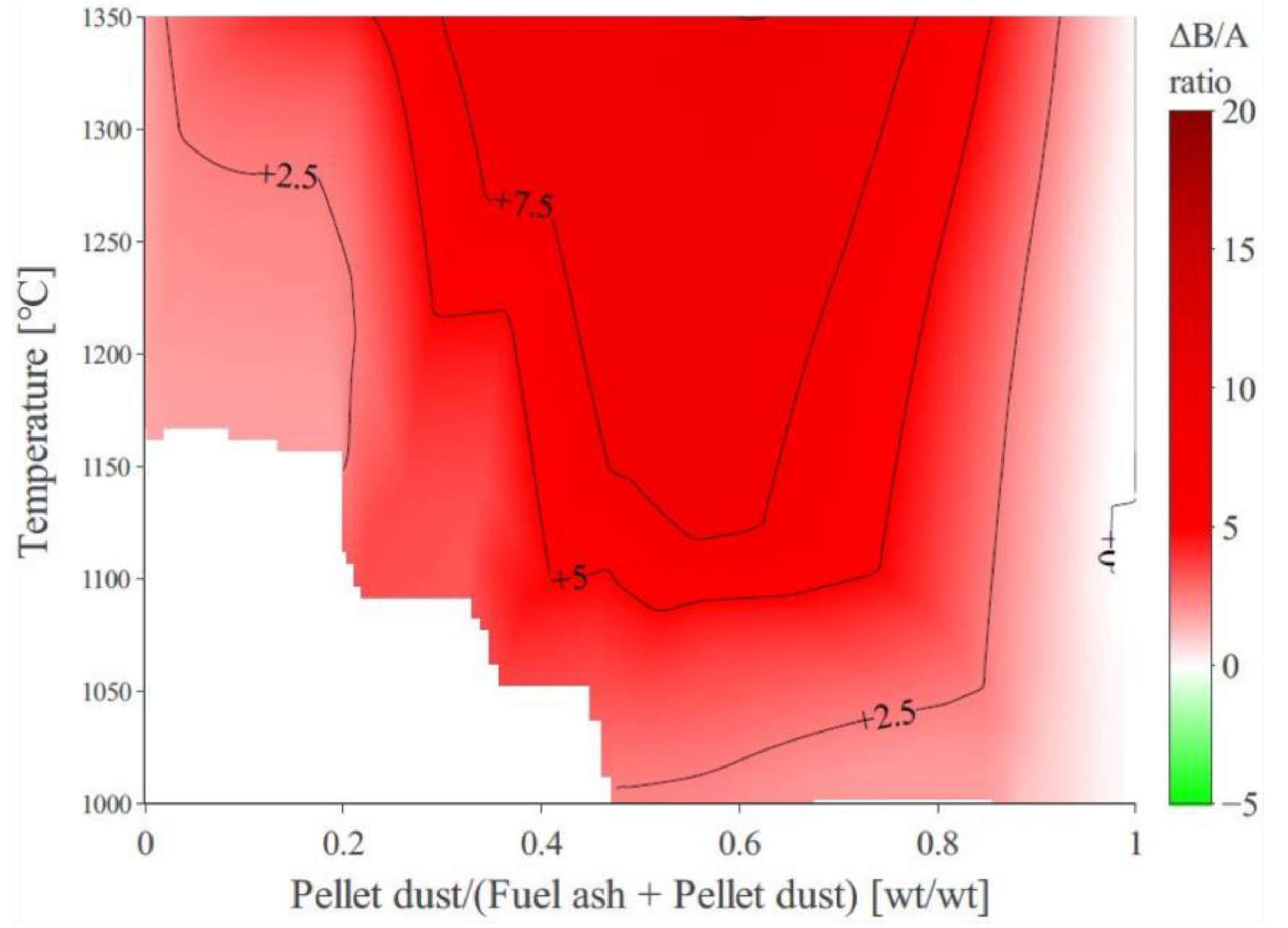
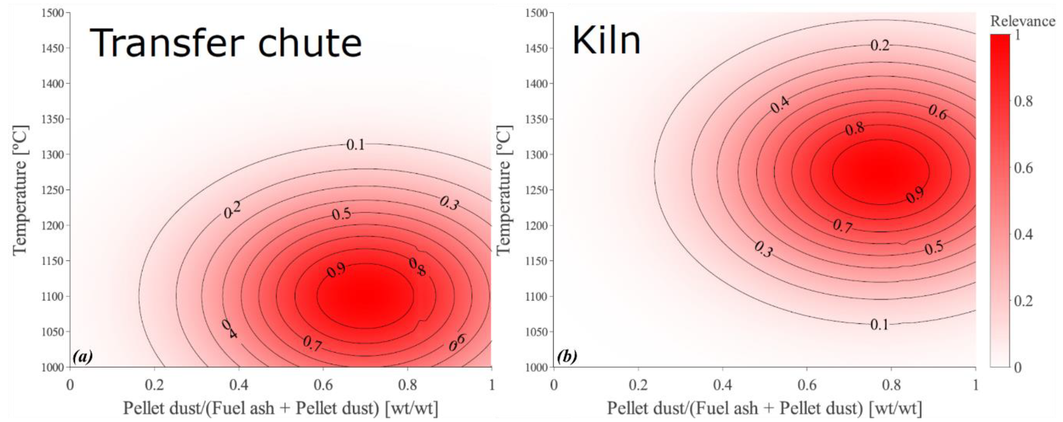
3.4. Quantification of the Absolute Deposition Tendency across the Studied Domain

In order to compare the investigated fuels based on the ADTs, as already discussed and elaborated upon, one can compare the Δ(ADT)plots with the assigned references, e.g., coal and stem wood. However, in order to make a readily discernable comparison, the following quantification approach was taken. The ADTs were summed up across the studied domain, i.e., 1000–1500 °C and 0–1 fraction of pellet dust under the following definition:
A b s o l u t e   s l a g g i n g   i n t e n s i t y = i = 1000 1500 j = 0 1 f i j × A D T i j
where “f” is a function quantifying the level of relevance or importance concerning slagging complexities encountered in a certain region or domain of the rotary kiln. For instance, the transfer chute which is reportedly one the most problematic regions of the grate-kiln setup (with regard to deposition) is given a relevance value of one (see Figure 9a), where the temperature is between 1050 and 1250 °C and the share of pellet dust in the deposits sampled at the transfer chute is from 60 to 80 wt.%. The function can be thought of as a probability function assigning a high importance/relevance value (unity) to the areas of interest while moving away from this region of interest, the relevance values gradually decrease until they approach zero when, for instance, the temperature is too high, e.g., 1500 °C and/or the share of pellet dust is too low (so-called irrelevant/inconsequential regions with respect to slagging-related issues). Multiple summation of the ADTs (Equation (2)), as expressed by Equation (4), across the studied domain, will yield a single value for each case, which can sort the investigated fuels based on their slagging potential. The quantified values for all the 15 biomass fuels and the reference coal are shown in column A of Table 1 (in ascending order). Clearly, the smaller the value, the lower the slagging potential.
However, some of the results were counterintuitive because the depicted order demonstrated in Table 1 (column A), in some instances, proved contrary to common-sense expectations. For instance, it is unexpected that the biochar of bark is predicted to exhibit a lower slagging tendency than its raw biomass since their ash compositions are, to a great extent, alike, and only their ash contents differ significantly from one another. The foregoing applies to the biochar of stem wood and biochar of willow as well, both of which are surprisingly predicted to have a lower slagging tendency than their respective raw biomasses. On a side note, notice that the predicted values for the slagging potential of the above-mentioned anomalous cases are considerably close to one another, e.g., the value predicted for the bark-biochar is comparable to that predicted for the raw bark. The reason for the above-mentioned anomalies is because Equation (2) was initially developed for high-rank coals with similar ash contents, whereas in this study the investigated biochars have a considerably higher ash content than their raw-biomass counterparts. However, as extensively discussed in the authors’ previous publications [6,7,20,21], the strength of the deposited matter (the degree of sintering) is also a deciding factor that could readily complicate/facilitate the process of deposit removal. The degree of sintering is inversely correlated to the viscosity (Watt [60,61], Mackenzie and Shuttleworth [62], and Boow [63]). Therefore, the QSI and Equation (2) (derived from the definition of QSI) could be used as a measure of deposit strength (Table 1, column A) rather than the slagging/deposition tendency.
Sensitivity analysis proved that, given the non-acidic ash chemistry associated with the investigated fuels in this study (as opposed to the acidic coal ashes studied previously23,24), the significance of viscosity (in Equation (2)) considerably overshadows the effect of the ash content. Therefore, the following intuitive correction was suggested to take the ash content into greater consideration than just the kg molten fraction stated in Equation (2).
A D T   ~   ( a s h   c o n t e n t / L H V ) ×   log ( k g   m o l t e n   a s h h r × 1 v i s c o s i t y ( P a . s ) )
Equation (5) was modified from Equation (2) such that the ADTs calculated by Equation (2) were normalized by the ash content per MJ of feedstock [kg/MJ] (calculated from the ash content and the respective lower heating value (LHV) of the raw/bio-oil/biochar). A similar numerical slagging index (NSI), which was primarily developed to determine the effect of incoming ash particles, was recently extended to and experimentally verified for coal/biomass blends by others [64,65,66,67]. The NSI bears a considerable resemblance to Equation (5) in that it too relates the slagging tendency to the reciprocal of ash viscosity and is directly proportional to the ash loading, i.e., the amount of input ash per hour [64,65,66,67].
The corrected ADTs (Equation (5)) were inserted in Equation (4) to quantify the slagging tendencies using the corrected ADTs. The results are shown in column B of Table 1 where a reasonable ranking of the investigated fuels (with respect to the slagging tendency) was achieved. The experimental verification of Equation (5) was not deemed necessary at the time of compiling the current work since, first and foremost, it is a derivation of Equation (2), which was previously proposed by the authors [21]. Secondly, the above-mentioned NSI has already been validated by others [64,65,66,67]. However, the necessity of such verification is recognized and has yet to be implemented in the authors’ future work.
As well as the transfer chute, other regions of the grate-kiln setup are also affected by deposit build-up, which in turn could inflict additional production losses and damage, for instance, the hot temperature region extending from the flame all the way to the inlet of the rotary kiln (herein referred to as the kiln). The relatively high temperature throughout the rotary kiln gives rise to ring formation, which is allegedly a major complication in iron-ore pelletizing [10,35]. Reportedly, ring formation requires temperatures upward of 1250 °C [68], a condition that is readily met inside the rotary kiln and not at the transfer chute. Therefore, it is of interest to assess the slagging potential of the investigated fuels in the kiln region as well, a region well-exposed to high temperatures hence susceptible to ring formation. Accordingly, similar to what was carried out previously for the transfer chute, the kiln region is given a relevance value of one (see Figure 9b), where the temperature is between 1200 and 1350 °C and the share of pellet dust in the deposits from the kiln region is slightly higher [69] than that in the transfer chute.
Multiple summation of the corrected ADTs (Equation (5)), as expressed by Equation (4), across the studied domain (the kiln) yields a single value for each case. The quantified values for all the 15 biomass fuels and the reference coal predicted for the kiln region are shown in column C of Table 1 (in ascending order). According to the results, the order observed in column B no longer holds true for the kiln region. For instance, in contrast to the biomasses, the coal is predicted to have a much greater slagging potential and cause severe slagging. The investigated high-rank coal has a resilient ash and, according to the TECs has a low melt/slag fraction at the temperature of the transfer chute, whereas within the rotary kiln the temperature is high enough to increase the melt fraction and decrease the viscosity low enough to inflict slagging. Another reason for the observed difference in the fuel sorting between the transfer chute and the kiln (column B vs. C in Table 1) is the chemical composition of the biomasses compared to that of the coal ash. The biomass ash possesses a high portion of alkalis which are readily volatile at the kiln temperature (a lower share of condensed phases, i.e., lower potential for slagging), whereas as the resilient coal ash is primarily composed of refractory elements, e.g., Si and Al. Therefore, with the exception of the biochars (apart from stem wood-biochar), the rest of the investigated biomasses are predicted to cause less slagging in the kiln region when compared to coal. According to column C in Table 1, stem wood biochar is the only fuel among the investigated biochars which is predicted to have a lower slagging tendency than coal, which is due to its low ash content.

3.5. The Effect of Biomass-Ash Composition upon Slagging When Interacting with Pellet Dust

The effect of biomass-ash composition upon the problematic slagging encountered in iron-ore pelletizing can be explained by means of phase diagrams.
On account of the fact that the investigated biomasses are all rich in calcium, the CaO-FeOx binary diagram was calculated in air (see Figure 10a). The calculated phase diagram (Figure 10a) demonstrates good agreement with those obtained through experiments after Phillips and Muan [70]. The two peritectic reactions (Figure 10a) take place well below 1250 °C, which is the highest temperature typically measured at the transfer-chute. More significantly, there is a eutectic at approximately 80 wt.% Fe2O3 where the temperature (liquidus) falls as low as 1205 °C (eutectic temperature). Accordingly, it is likely that the calcium-rich biomass-ash may react with the Fe-rich pellet dust, which can give rise to the formation of low-melting-point compounds, thereby intensifying slagging.
Likewise, calcium can decrease the liquidus temperature through reacting with Si, which is the second major ash forming element in the pellet dust. The calculated CaO-SiO2 binary phase diagram is shown in Figure 10b (the corresponding experimental phase diagram can be found elsewhere [71]). The lowermost eutectics in the system take place at 1436 and 1460 °C at around 37 and 55 CaO wt.%. It is worth mentioning that although the above-mentioned temperatures are noticeably high, the temperature can still be drastically lowered with the inclusion of other ash forming elements. However, the importance of Figure 10b lies in the fact that it signposts a thermodynamic driving force capable of lowering the temperature through the above-mentioned eutectic reactions. Calcium can potentially react with the silicon contained in the Fe-rich particles and be incorporated in the resulting melt where the inclusion of CaO (which is a fluxing agent) can reduce the viscosity and lead to the formation of sturdier deposits. Note that the Si/Ca ratios corresponding to the above-mentioned eutectics can readily occur during the iron-ore pelletizing process.
However, further substantiation by experiments is still required, especially in order to establish how biomass ashes and pellet dust particles interact, thereby strengthening the predicted scenarios.

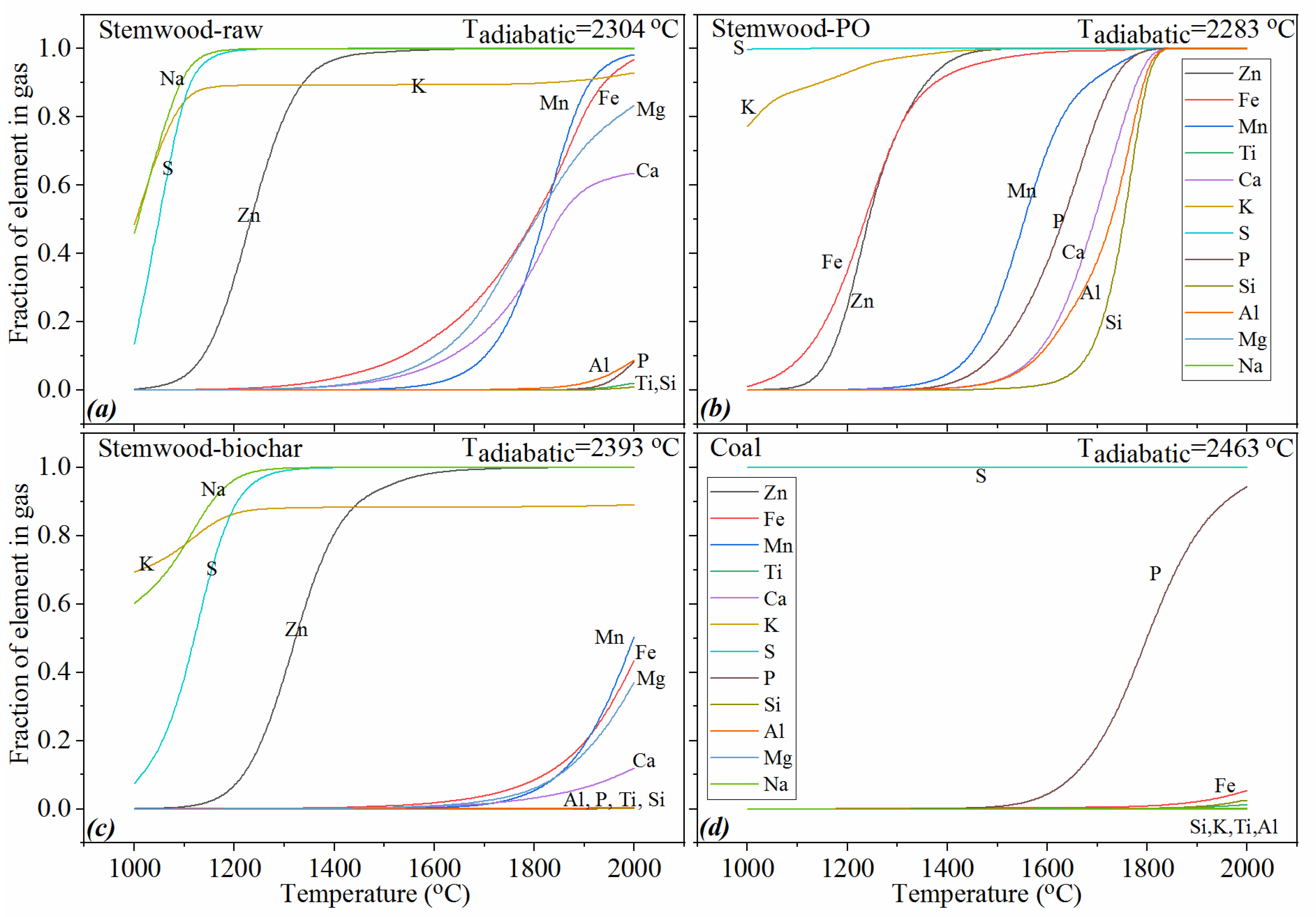
3.6. The Volatile Behavior of Ash in the Investigated Cases

Dependent on the composition of the fine particles, several particle pathways are expected to take place in a grate-kiln setup. Particles that are mainly composed of refractory elements are likely to occur in the particulate phase within the flame. As previously observed [69], when the carrier gas passes across the pellet bed, a significant portion of these particles pile up on the exterior surface of the pellets. These particles are thus carried along with the pellets, enter the kiln, annular cooler, and ultimately wind up in the finished product.
On the other hand, the submicron particles that consist of readily volatile inorganic elements (e.g., sulfur, chlorine, and alkali) are expected to exist as gases outside the flame due to the high-temperature atmosphere in the kiln. When the gas enters the lower part of the pellet bed, the saturated inorganic vapor, containing fume (submicron) particles, starts to condense onto the surface of the pellets. Note that, reportedly, gas temperature could get as low as 800 °C at the bottom of the pellet bed right at the inlet of the rotary kiln [72]. However, when the temperature of the pellets rises to 1200–1250 °C in the kiln, these elements are vaporized again. The preceding considerations suggest that these particles are supposed to recirculate (through vaporization within the flame, condensation in the low-temperature zones, and vaporization again in the kiln) throughout the entire process. Consequently, the concentration of these volatile inorganic elements could increase with time. The accumulation of readily volatile inorganic elements (particularly alkalis) can intensify deposition as well as alkali infiltration in the refractory linings of the furnace [10]. In connection with the above-mentioned concerns, it might be a risk to burn fuels that can generate a high quantity of fume particles because the concentration of readily volatile inorganic elements will increase at a faster rate. Therefore, the volatile behavior of the investigated fuels was explored using thermochemical equilibrium calculations.
The fraction of the inorganic elements in the gas phase was predicted for stem wood, stem wood-PO, stem wood-biochar, and the reference coal (Figure 11a–d). The results suggest that stem wood-PO exhibits the most volatility, followed by stem wood-raw, stem wood-biochar, and the reference coal. The reference coal has the lowest volatility of the ash forming elements since its ash is dominated by refractory elements rather than readily volatile elements such as alkalis, which are pervasive in the studied biomasses. Over 40 wt.% of the ash forming matter in the stem wood-PO would be in the gas phase even at relatively low temperatures, e.g., 1100 °C, which is the average temperature measured at the transfer-chute (Figure 12a). However, the POs have the lowest ash content; therefore, in order to make a practical comparison between the investigated fuels (in terms of the volatility of their ashes), the total amount of vaporized ash was calculated as follows:
V a p o r i z e d   a s h =     ( a s h   c o n t e n t / L H V ) ×   % v a p o r i z e d   a s h    
where %vaporized ash (see Figure 12a) is the total amount of inorganic elements in the gas phase divided by the total amount of inorganic elements in the ash. The calculation of %vaporized ash was carried out notwithstanding the S and Cl content of the fuels since these elements are highly volatile irrespective of the fuel (see Figure 11a–d). The total amount of vaporized ash (mg/MJ) for all the investigated fuels (calculated according to Equation (6)) is presented in the Supplementary Materials (Section E).
The results (for stem wood, stem wood-PO, stem wood-biochar, and the reference coal), as plotted against temperature in Figure 12b, indicate that the combustion of stem wood-PO and coal is predicted to form the lowest amount of fumes in the gas phase. However, considering the distribution of the vaporized inorganic elements for the reference coal (Figure 11d), the volatile elements are largely limited to S and P. The former was excluded as mentioned above, but P is still significantly affecting the results. According to the results (Figure 11), no significant vaporization of alkalis was predicted for the reference coal, especially at temperatures as low as the gas temperature at the bottom of the pellet bed (which is, reportedly, in the order of 800–1000 °C at the inlet of the rotary kiln [72]). Therefore, the reference coal is less likely to contribute to the problematic alkali recirculation phenomenon (as well as accumulations of fine particles) followed by stem wood-PO, stem wood-raw, and stem wood-biochar.
Furthermore, the amount of condensed inorganic vapor was determined, taking an arbitrary flame temperature typically measured/calculated for the specific suspension-firing burners in question. The results are plotted in Figure 13 showing the amount of the gaseous inorganic elements (inorganic vapors/fumes) that condenses as the temperature drops from an arbitrary flame temperature to 1000 °C (which is the temperature at the bottom of the pellet bed right at the inlet of the rotary kiln [72] where alkali recirculation is at its zenith). It is also assumed that the condensed inorganic vapors transform into fine particles through recondensation/nucleation of the vaporized ash, which is the mechanism responsible for the formation of submicron particles [73,74,75,76,77,78].
The results presented in Figure 13 could help rank the investigated fuels with respect to the predicted amount of submicron particles (calculated in mg/MJ) that form on account of the above-mentioned temperature decrease. Clearly, the lower the predicted value, the more desirable the fuel.

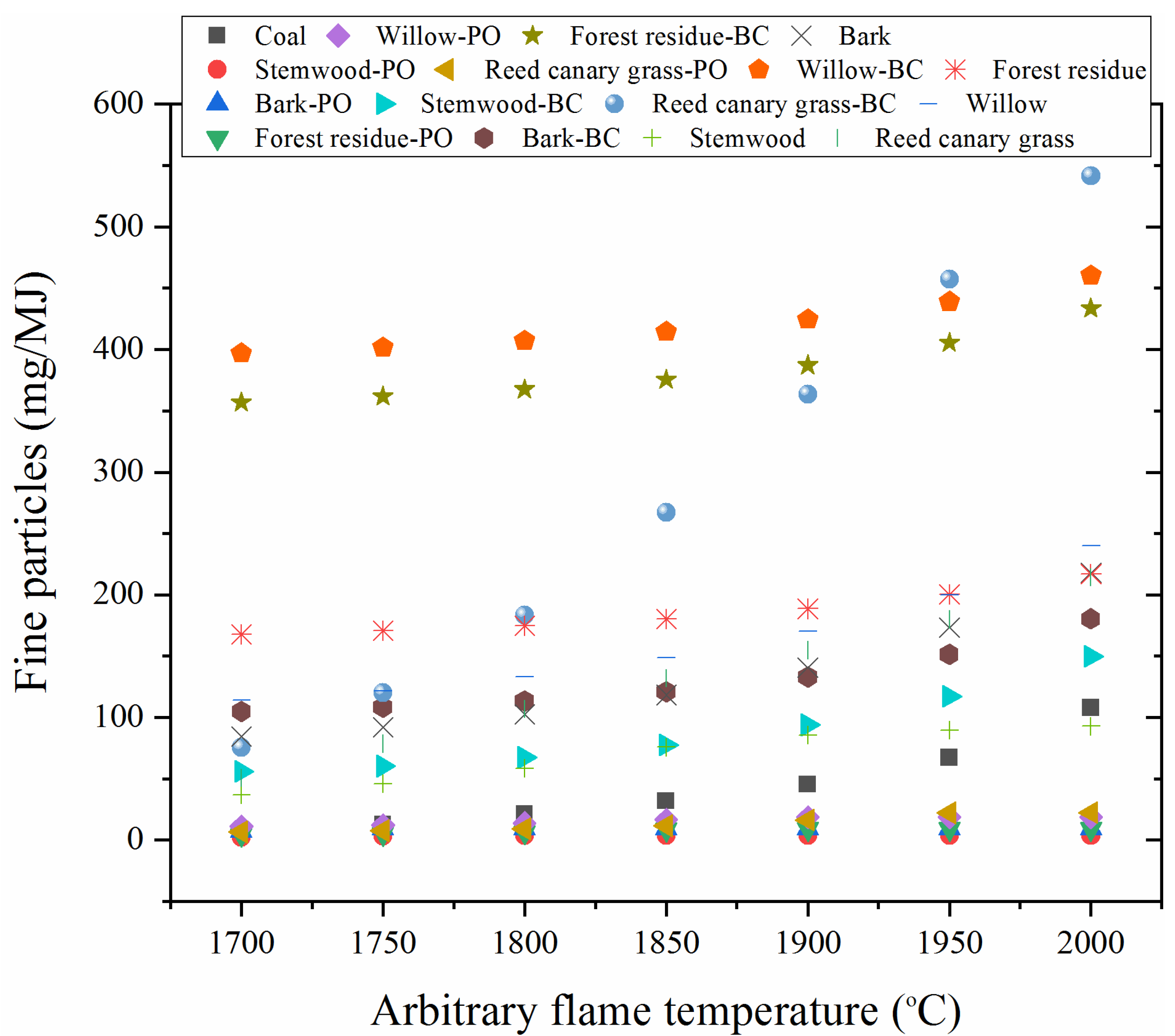
3.7. Practical Implications

The quantified slagging potential, the volatile behavior of ash, and, in general, the overall results and discussion presented thus far could be abridged and presented in a condensed form, especially when considering certain objectives that involve practicality. Therefore, the somewhat broad-ranging results presented/discussed so far are broadly classified into a number of practical key values, each of which is assigned to a specific ash-related complication associated with the grate-kiln setup:
Key values_1 and 2: the most important practical aspect of the current work is to answer whether the rate of slagging/deposition could be alleviated, or at least not substantially intensified, as a result of replacing the reference coal with any of the investigated renewable candidates. Given the foregoing, the ADTs quantified using Equation (5) could be considered a key value which could potentially gauge the slagging propensity. Based on the location of interest, Key value_1 is assigned to the predicted slagging potential at the transfer-chute and Key value_2 to that inside the rotary kiln (Table 1, columns B and C, respectively).
Key value_3: as extensively discussed in the authors’ previous publications [6,7,20,21], the strength of the deposited matter (the degree of sintering) is also a deciding factor that could readily complicate/facilitate the process of deposit removal. The degree of sintering (deposit strength) is inversely correlated to the viscosity (Watt [60,61], Mackenzie and Shuttleworth [62], and Boow [63]). Therefore, the QSI and Equation (2) (derived from the definition of QSI) could be used as a measure of deposit strength (Table 1, column A).
Key value_4: as previously discussed (Section 3.6), the volatile behavior of ash is also a significant factor that can affect the fuel choice. Therefore, considering the discussion made in Section 3.6, the predicted amount of submicron particles was considered a key factor.
Accordingly, based on the results presented in Table 1 and Section 3.6, the three biomass categories investigated in this study are compared with one another and the reference coal as tabulated in Table 2. Note that for Key value_4, the presented order is that obtained at the arbitrary flame temperature of 1800 °C (see Figure 13). The highlighted fuels are predicted to be suitable for iron-ore pelletizing with respect to the key value in question.
According to the results, the predicted slagging/deposition tendencies of all the pyrolysis products of the investigated biomass fuels at the transfer-chute are comparable to that of coal (Key value_1). The preceding suggests that in case the slagging encountered at the transfer-chute is considered a major technological bottleneck, then replacing coal with any of the above-mentioned upgraded fuels (POs) is most likely preferable. However, according to the predictions, the situation within the rotary kiln is totally different where all the investigated POs and raw biomasses were predicted to cause less slagging compared to the reference coal. Therefore, should the decision-makers deem the rotary kiln as the most critical region, then all the investigated renewable fuels, except for the biochars, seem to be superior to the reference coal. However, since the ash viscosity of all the renewable candidates was estimated to be lower than that of the coal, it is likely that more tenacious/resilient deposits are going to form as a result of biomass combustion. Furthermore, the combustion of POs and coal is predicted to form the lowest amount of fumes in the gas phase. However, considering the distribution of the vaporized inorganic elements for the reference coal (Figure 11d), the volatile elements are largely limited to S and P. Therefore, the reference coal is less likely to contribute to the problematic alkali recirculation phenomenon (as well as accumulations of fine particles) followed by the POs.
Considering the predefined key values altogether, the pyrolysis oils (POs) seem to be the most promising alternative to the reference coal. Furthermore, only when slagging within the rotary kiln is concerned, given the slagging potential predicted for the raw biomasses and the biochar of stem wood, the aforementioned alternatives also prove promising and could be considered for full-scale experimental trials.

4. Conclusions

In this study, the effect of the interaction between the pellet dust and biomass-ash upon melt formation and the viscosity of the resulting melt was theoretically assessed. The slagging potential of 15 different biomass fuels was quantified and compared with one another and a reference high-rank coal using a proposed slagging index, a similar form of which was previously validated by others.
The quantified slagging/deposition potentials at the transfer-chute suggest that only the pyrolysis oils are comparable to the reference coal while the rest of the renewable candidates are expected to aggravate the situation.
However, slagging/deposition within the rotary kiln is predicted to be alleviated as a result of biomass combustion. The foregoing applies to all the investigated renewable candidates except for the biochars.
Furthermore, among the investigated fuels, only the reference coal and the pyrolysis oils are less likely to contribute to the accumulations of fine particles, whereas the rest of the investigated fuels are expected to impose a negative impact on the formation of fine particles.
Given that the viscosity of coal ash is estimated to be the highest among the investigated fuels, less tenacious/resilient deposits are likely to form, which makes ash-handling/removal less challenging for the reference coal compared to the rest of the fuels.
Considering all aspects of the ash-related complications addressed in the present work, the pyrolysis oils are expected to be the most viable alternative to the reference coal. Moreover, only insofar as slagging within the rotary kiln is concerned, the raw biomasses as well as the biochar of stem wood are considered practicable alternatives, the performance of which is worthwhile to be put to the test in a full-scale grate-kiln facility. On the other hand, all the investigated biochars, except for stem wood-biochar, are likely to exacerbate the impact of the existing ash-related challenges encountered in iron-ore pelletizing grate-kilns.

Supplementary Materials

The following are available online at https://www.mdpi.com/1996-1073/13/20/5386/s1.

Author Contributions

H.W., B.L., and L.-O.N. conceived the original idea and were in charge of overall planning and direction. H.S. developed the theory and carried out the TECs. H.S. and H.W. analyzed and interpreted the results and answered the research questions in consultation with B.L. and L.-O.N. H.S. wrote the manuscript with input from all authors. All authors have read and agreed to the published version of the manuscript.

Funding

This research was funded by the Swedish Energy Agency, grant number 42684-2, HYBRIT (Hydrogen Breakthrough Ironmaking Technology)—Research project 1.

Acknowledgments

This work has been conducted as part of the HYBRIT research project RP1. We gratefully acknowledge the financial support from the Swedish Energy Agency. HYBRIT (Hydrogen Breakthrough Ironmaking Technology) is a joint initiative of the three companies SSAB, LKAB and Vattenfall with the aim of developing the world’s first fossil-free ore-based steelmaking route.

Conflicts of Interest

The authors declare no conflict of interest.

References

  1. De Moraes, S.L.; De Lima, J.R.B.; Ribeiro, T.R. Iron Ore Pelletizing Process: An Overview. In Iron Ores and Iron Oxide Materials; IntechOpen: London, UK, 2018. [Google Scholar]
  2. Forsmo, S.; Vuori, J. The determination of porosity in iron ore green pellets by packing in silica sand. Powder Technol. 2005, 159, 71–77. [Google Scholar] [CrossRef]
  3. Forsmo, S.; Forsmo, S.-E.; Samskog, P.-O.; Björkman, B. Mechanisms in oxidation and sintering of magnetite iron ore green pellets. Powder Technol. 2008, 183, 247–259. [Google Scholar] [CrossRef]
  4. Potts, R. Induration of taconite pellets using a grate kiln system. In Annual Meeting of the Minnesota Section, AIME; The Section: Minneapolis, MN, USA, 1991. [Google Scholar]
  5. Forsmo, S. Influence of Green Pellet Properties on Pelletizing of Magnetite Iron Ore; Luleå Tekniska Universitet: Luleå, Sweden, 2007. [Google Scholar]
  6. Sefidari, H.; Lindblom, B.; Wiinikka, H.; Nordin, L.-O.; Mouzon, J.; Bhuiyan, I.U.; Öhman, M. The effect of disintegrated iron-ore pellet dust on deposit formation in a pilot-scale pulverized coal combustion furnace. Part I: Characterization of process gas particles and deposits. Fuel Process. Technol. 2018, 177, 283–298. [Google Scholar] [CrossRef]
  7. Sefidari, H.; Lindblom, B.; Wiinikka, H.; Nordin, L.-O.; Lennartsson, A.; Mouzon, J.; Bhuiyan, I.U.; Öhman, M. The effect of disintegrated iron-ore pellet dust on deposit formation in a pilot-scale pulverized coal combustion furnace. Part II: Thermochemical equilibrium calculations and viscosity estimations. Fuel Process. Technol. 2018, 180, 189–206. [Google Scholar] [CrossRef]
  8. Bandyopadhyay, R.; Gupta, S.; Lindblom, B.; Jonsson, S. In effect of coal ash characteristics on ash deposition in rotary kilns. In Proceedings of the 4th International Conference on Process Development in Iron and Steelmaking (SCANMET IV), Swerea Mefos, Lulea, Sweden, 10–13 June 2012. [Google Scholar]
  9. Lindblom, B.; Fredriksson, C.; Jonsson, S.; Nordin, L.-O.; Wiinikka, H. Pilot scale tests of different coals for the usage in the grate-kiln process at LKAB. In Proceedings of the International Conference on Applied Energy ICAE, Suzhou, China, 5–8 July 2012. [Google Scholar]
  10. Stjernberg, J.; Ion, J.; Antti, M.-L.; Nordin, L.-O.; Lindblom, B.; Odén, M. Extended studies of degradation mechanisms in the refractory lining of a rotary kiln for iron ore pellet production. J. Eur. Ceram. Soc. 2012, 32, 1519–1528. [Google Scholar] [CrossRef]
  11. Jonsson, C.Y.; Stjernberg, J.; Wiinikka, H.; Lindblom, B.; Boström, D.; Öhman, M. Deposit Formation in a Grate-Kiln Plant for Iron-Ore Pellet Production. Part 1: Characterization of Process Gas Particles. Energy Fuels 2013, 27, 6159–6170. [Google Scholar] [CrossRef]
  12. Stjernberg, J.; Jonsson, C.Y.; Wiinikka, H.; Lindblom, B.; Boström, D.; Öhman, M. Deposit Formation in a Grate–Kiln Plant for Iron-Ore Pellet Production. Part 2: Characterization of Deposits. Energy Fuels 2013, 27, 6171–6184. [Google Scholar] [CrossRef]
  13. Jonsson, C.; Wiinikka, H.; Lindblom, B.; Stjernberg, J.; Öhman, M. Comparison of particle and deposit formation between a full-scale grate-kiln plant (40 MW) and a pilot-scale pulverised coal-fired furnace (400 kW). In Proceedings of the International Conference on Applied Energy: Energy Solution for a Sustainable World, Pretoria, South Africa, 1–5 July 2013. [Google Scholar]
  14. Stjernberg, J.; Isaksson, O.; Ion, J. The grate-kiln induration machine—History, advantages, and drawbacks, and outline for the future. J. South. Afr. Inst. Min. Met. 2015, 115, 137–144. [Google Scholar] [CrossRef] [Green Version]
  15. Bryers, R.W. Fireside slagging, fouling, and high-temperature corrosion of heat-transfer surface due to impurities in steam-raising fuels. Prog. Energy Combust. Sci. 1996, 22, 29–120. [Google Scholar] [CrossRef]
  16. Benson, S.A.; Hurley, J.P.; Zygarlicke, C.J.; Steadman, E.N.; Erickson, T.A. Predicting ash behavior in utility boilers. Energy Fuels 1993, 7, 746–754. [Google Scholar] [CrossRef]
  17. Benson, S.A.; Erickson, T.A.; Jensen, R.R.; Laumb, J.D. Transformations model for predicting size and composition of ash during coal combustion. Fuel Chem. Div. Prepr. 2002, 47, 796. [Google Scholar]
  18. Srinivasachar, S.; Senior, C.L.; Helble, J.; Moore, J. A fundamental approach to the prediction of coal ash deposit formation in combustion systems. Symp Combust. 1992, 24, 1179–1187. [Google Scholar] [CrossRef]
  19. Raask, E. Mineral Impurities in Coal Combustion: Behavior, Problems, and Remedial Measures; Taylor & Francis: Leatherhead, UK, 1985. [Google Scholar]
  20. Sefidari, H.; Wiinikka, H.; Lindblom, B.; Nordin, L.; Wu, G.; Yazhenskikh, E.; Müller, M.; Ma, C.; Öhman, M. Comparison of high-rank coals with respect to slagging/deposition tendency at the transfer-chute of iron-ore pelletizing grate-kiln plants: A pilot-scale experimental study accompanied by thermochemical equilibrium modeling and viscosity estimations. Fuel Process. Technol. 2019, 193, 244–262. [Google Scholar] [CrossRef]
  21. Sefidari, H.; Ma, C.; Fredriksson, C.; Lindblom, B.; Wiinikka, H.; Nordin, L.; Wu, G.; Yazhenskikh, E.; Müller, M.; Öhman, M. The effect of co-firing coal and woody biomass upon the slagging/deposition tendency in iron-ore pelletizing grate-kiln plants. Fuel Process. Technol. 2020, 199, 106254. [Google Scholar] [CrossRef]
  22. Wiinikka, H.; Sepman, A.; Ögren, Y.; Lindblom, B.; Nordin, L.O. Combustion Evaluation of Renewable Fuels for Iron-Ore Pellet Induration. Energy Fuels 2019, 33, 7819–7829. [Google Scholar] [CrossRef]
  23. Boström, D.; Skoglund, N.; Grimm, A.; Boman, C.; Öhman, M.; Broström, M.; Backman, R. Ash Transformation Chemistry during Combustion of Biomass. Energy Fuels 2011, 26, 85–93. [Google Scholar] [CrossRef]
  24. Kleinhans, U.; Wieland, C.; Frandsen, F.J.; Spliethoff, H. Ash formation and deposition in coal and biomass fired combustion systems: Progress and challenges in the field of ash particle sticking and rebound behavior. Prog. Energy Combust. Sci. 2018, 68, 65–168. [Google Scholar] [CrossRef]
  25. Zhou, H.; Ma, W.; Zhang, J.; Xu, Y.; Zhao, M. Ash deposition behavior under coal and wood co-firing conditions in a 300 kW downfired furnace. J. Energy Inst. 2018, 91, 743–755. [Google Scholar] [CrossRef]
  26. Wiinikka, H.; Carlsson, P.; Johansson, A.-C.; Gullberg, M.; Ylipää, C.; Lundgren, M.; Sandström, L. Fast Pyrolysis of Stem Wood in a Pilot-Scale Cyclone Reactor. Energy Fuels 2015, 29, 3158–3167. [Google Scholar] [CrossRef]
  27. Johansson, A.-C.; Wiinikka, H.; Sandström, L.; Marklund, M.; Öhrman, O.; Narvesjö, J. Characterization of pyrolysis products produced from different Nordic biomass types in a cyclone pilot plant. Fuel Process. Technol. 2016, 146, 9–19. [Google Scholar] [CrossRef]
  28. Wiinikka, H.; Johansson, A.-C.; Sandström, L.; Öhrman, O. Fate of inorganic elements during fast pyrolysis of biomass in a cyclone reactor. Fuel 2017, 203, 537–547. [Google Scholar] [CrossRef]
  29. Sefidari, H. Mechanisms of Deposit Formation in the Grate-kiln Process; Luleå Tekniska Universitet: Luleå, Sweden, 2018. [Google Scholar]
  30. Carlsson, P.; Ma, C.; Molinder, R.; Weiland, F.; Wiinikka, H.; Öhman, M.; Öhrman, O. Slag Formation during Oxygen-Blown Entrained-Flow Gasification of Stem Wood. Energy Fuels 2014, 28, 6941–6952. [Google Scholar] [CrossRef]
  31. Ma, C.; Backman, R.; Öhman, M. Thermochemical Equilibrium Study of Slag Formation during Pressurized Entrained-Flow Gasification of Woody Biomass. Energy Fuels 2015, 29, 4399–4406. [Google Scholar] [CrossRef]
  32. Carlborg, M.; Weiland, F.; Ma, C.; Backman, R.; Landälv, I.; Wiinikka, H. Exposure of refractory materials during high-temperature gasification of a woody biomass and peat mixture. J. Eur. Ceram. Soc. 2018, 38, 777–787. [Google Scholar] [CrossRef]
  33. Ma, C.; Carlborg, M.; Hedman, H.; Wennebro, J.; Weiland, F.; Wiinikka, H.; Backman, R.; Öhman, M. Ash Formation in Pilot-Scale Pressurized Entrained-Flow Gasification of Bark and a Bark/Peat Mixture. Energy Fuels 2016, 30, 10543–10554. [Google Scholar] [CrossRef]
  34. Jonsson, C. Deposit Formation in the Grate-Kiln Process; Luleå Tekniska Universitet: Luleå, Sweden, 2013. [Google Scholar]
  35. Tao, J.; Guo-qiang, H.; Min, G.; Guang-hui, L.; Xiao-hui, F.; Li-shun, Y. Forming mechanism of rings in rotary-kiln for oxidized pellet. J. Iron Steel Res. Int. 2009, 16, 292–297. [Google Scholar]
  36. Allendorf, M.D.; Spear, K.E. Thermodynamic Analysis of Silica Refractory Corrosion in Glass-Melting Furnaces. J. Electrochem. Soc. 2001, 148, B59–B67. [Google Scholar] [CrossRef]
  37. Hack, K.; Jantzen, T.; Müller, M.; Yazhenskikh, E.; Wu, G. A novel thermodynamic database for slag systems and refractory materials. In Proceedings of the 5th International Congress on the Science and Technology of Steelmaking, Dresden, Germany, 20 October 2012. [Google Scholar]
  38. Bale, C.; Bélisle, E.; Chartrand, P.; Decterov, S.; Eriksson, G.; Hack, K.; Jung, I.-H.; Kang, Y.-B.; Melançon, J.; Pelton, A.; et al. FactSage thermochemical software and databases—Recent developments. Calphad 2009, 33, 295–311. [Google Scholar] [CrossRef]
  39. Bale, C.; Chartrand, P.; Degterov, S.; Eriksson, G.; Hack, K.; Ben Mahfoud, R.; Melançon, J.; Pelton, A.; Petersen, S. FactSage thermochemical software and databases. Calphad 2002, 26, 189–228. [Google Scholar] [CrossRef]
  40. Koukkari, P.; Penttilä, K.; Hack, K.; Petersen, S. CHEMSHEET—An Efficient Worksheet Tool for Thermodynamic Process Simulation. In Microstructures, Mechanical Properties and Processes—Computer Simulation and Modelling; Wiley-VCH: Weinheim, Germany, 2005; Volume 3, pp. 323–330. [Google Scholar]
  41. Nentwig, T.; Kondratiev, A.; Yazhenskikh, E.; Hack, K.; Müller, M. Viscosity Model for Oxide Melts Relevant to Coal Ash Slags Based on the Associate Species Thermodynamic Model. Energy Fuels 2013, 27, 6469–6476. [Google Scholar] [CrossRef]
  42. Wu, G.; Yazhenskikh, E.; Hack, K.; Wosch, E.; Müller, M. Viscosity model for oxide melts relevant to fuel slags. Part 1: Pure oxides and binary systems in the system SiO2–Al2O3–CaO–MgO–Na2O–K2O. Fuel Process. Technol. 2015, 137, 93–103. [Google Scholar] [CrossRef]
  43. Wu, G.; Yazhenskikh, E.; Hack, K.; Müller, M. Viscosity model for oxide melts relevant to fuel slags. Part 2: The system SiO2–Al2O3–CaO–MgO–Na2O–K2O. Fuel Process. Technol. 2015, 138, 520–533. [Google Scholar] [CrossRef]
  44. Wu, G.; Seebold, S.; Yazhenskikh, E.; Hack, K.; Müller, M. Viscosity model for oxide melts relevant to fuel slags. Part 3: The iron oxide containing low order systems in the system SiO2–Al2O3–CaO–MgO–Na2O–K2O–FeO–Fe2O3. Fuel Process. Technol. 2018, 171, 339–349. [Google Scholar] [CrossRef]
  45. Hack, K.; Wu, G.; Yazhenskikh, E.; Jantzen, T.; Müller, M. A CALPHAD approach to modelling of slag viscosities. Calphad 2019, 65, 101–110. [Google Scholar] [CrossRef]
  46. Wu, G.; Seebold, S.; Yazhenskikh, E.; Tanner, J.; Hack, K.; Müller, M. Slag mobility in entrained flow gasifiers optimized using a new reliable viscosity model of iron oxide-containing multicomponent melts. Appl. Energy 2019, 236, 837–849. [Google Scholar] [CrossRef]
  47. Vargas, S.; Frandsen, F.J.; Dam-Johansen, K. Rheological properties of high-temperature melts of coal ashes and other silicates. Prog. Energy Combust. Sci. 2001, 27, 237–429. [Google Scholar] [CrossRef]
  48. Browning, G.J.; Bryant, G.W.; Hurst, H.J.; Lucas, J.; Wall, T.F. An Empirical Method for the Prediction of Coal Ash Slag Viscosity. Energy Fuels 2003, 17, 731–737. [Google Scholar] [CrossRef]
  49. Duchesne, M.A.; Bronsch, A.M.; Hughes, R.W.; Masset, P.J. Slag viscosity modeling toolbox. Fuel 2013, 114, 38–43. [Google Scholar] [CrossRef]
  50. Yazhenskikh, E.; Hack, K.; Müller, M. Critical thermodynamic evaluation of oxide systems relevant to fuel ashes and slags. Part 1: Alkali oxide–silica systems. Calphad 2006, 30, 270–276. [Google Scholar] [CrossRef]
  51. Yazhenskikh, E.; Hack, K.; Müller, M. Critical thermodynamic evaluation of oxide systems relevant to fuel ashes and slags Part 2: Alkali oxide–alumina systems. Calphad 2006, 30, 397–404. [Google Scholar] [CrossRef]
  52. Yazhenskikh, E.; Hack, K.; Müller, M. Critical thermodynamic evaluation of oxide systems relevant to fuel ashes and slags. Part 3: Silica–alumina system. Calphad 2008, 32, 195–205. [Google Scholar] [CrossRef]
  53. Yazhenskikh, E.; Hack, K.; Müller, M. Critical thermodynamic evaluation of oxide systems relevant to fuel ashes and slags, Part 4: Sodium oxide–potassium oxide–silica. Calphad 2008, 32, 506–513. [Google Scholar] [CrossRef]
  54. Yazhenskikh, E.; Hack, K.; Müller, M. Critical thermodynamic evaluation of oxide systems relevant to fuel ashes and slags, Part 5: Potassium oxide–alumina–silica. Calphad 2011, 35, 6–19. [Google Scholar] [CrossRef]
  55. Yazhenskikh, E.; Jantzen, T.; Hack, K.; Müller, M. Critical thermodynamic evaluation of oxide systems relevant to fuel ashes and slags: Potassium oxide–magnesium oxide–silica. Calphad 2014, 47, 35–49. [Google Scholar] [CrossRef]
  56. Brown, G.J. X-ray scattering and X-ray spectroscopy studies of silicate melts. Struct. Dyn. Prop. Silic. Melts 1995, 32, 317–410. [Google Scholar]
  57. Urbain, G. Viscosity estimation of slags. Steel Res. 1987, 58, 111–116. [Google Scholar] [CrossRef]
  58. Kondratiev, A.; Hayes, P.C.; Jak, E. Development of a Quasi-chemical Viscosity Model for Fully Liquid Slags in the Al2O3–CaO–‘FeO’–MgO–SiO2 System. Part 1. Description of the Model and Its Application to the MgO, MgO–SiO2, Al2O3–MgO and CaO–MgO Sub-systems. ISIJ Int. 2006, 46, 359–367. [Google Scholar] [CrossRef]
  59. Senior, C.L.; Srinivasachar, S. Viscosity of Ash Particles in Combustion Systems for Prediction of Particle Sticking. Energy Fuels 1995, 9, 277–283. [Google Scholar] [CrossRef]
  60. Watt, J. The Physical and Chemical Behaviour of the Mineral Matter in the Coal under the Conditions Met in Combustion Plant: A Literature Survey; Bcura Industrial Laboratories: Leatherhead, UK, 1968. [Google Scholar]
  61. Watt, J.; Fereday, F. The flow properties of slag formed from the ashes of British coals. J. Ind. Fuel 1969, 42, 89. [Google Scholar]
  62. MacKenzie, J.K.; Shuttleworth, R. A Phenomenological Theory of Sintering. Proc. Phys. Soc. Sect. B 1949, 62, 833–852. [Google Scholar] [CrossRef]
  63. Boow, J. Sodium/ash reactions in the formation of fireside deposits in pulverized-fuel-fired boilers. Fuel 1972, 51, 170–173. [Google Scholar] [CrossRef]
  64. Garba, M.; Ingham, D.; Ma, L.; Degereji, M.; Pourkashanian, M.; Williams, A. Modelling of deposit formation and sintering for the co-combustion of coal with biomass. Fuel 2013, 113, 863–872. [Google Scholar] [CrossRef]
  65. Balakrishnan, S.; Nagarajan, R.; Karthick, K. Mechanistic modeling, numerical simulation and validation of slag-layer growth in a coal-fired boiler. Energy 2015, 81, 462–470. [Google Scholar] [CrossRef]
  66. Degereji, M.; Ingham, D.; Ma, L.; Pourkashanian, M.; Williams, A. Numerical assessment of coals/blends slagging potential in pulverized coal boilers. Fuel 2012, 102, 345–353. [Google Scholar] [CrossRef]
  67. Degereji, M.; Ingham, D.B.; Ma, L.; Pourkashanian, M.; Williams, A. Prediction of ash slagging propensity in a pulverized coal combustion furnace. Fuel 2012, 101, 171–178. [Google Scholar] [CrossRef]
  68. Zhong, Q.; Yang, Y.; Jiang, T.; Li, Q.; Xu, B. Effect of coal ash on ring behavior of iron-ore pellet powder in kiln. Powder Technol. 2018, 323, 195–202. [Google Scholar] [CrossRef]
  69. Niininiskorpi, V. Development of Phases and Structures during Pelletizing of Kiruna Magnetite Ore; Åbo Akademi Finland: Turku, Finland, 2004. [Google Scholar]
  70. Phillips, B.; Muan, A. Phase Equilibria in the system CaO-Iron oxide in air and at 1 atm. O2 Pressure. J. Am. Ceram. Soc. 1958, 41, 445–454. [Google Scholar] [CrossRef]
  71. Phillips, B.; Muan, A. Phase Equilibria in the system CaO-Iron oxide-SiO2, in air. J. Am. Ceram. Soc. 1959, 42, 413–423. [Google Scholar] [CrossRef]
  72. Nilsson, E.A.A. Degradation Mechanisms of Heat Resistant Steel at Elevated Temperatures: In an Iron Ore Pelletizing Industry. Ph.D. Thesis, Luleå University of Technology, Luleå, Sweden, 1 January 1997. [Google Scholar]
  73. Flagan, R.; Friedlander, S. Particle formation in pulverized coal combustion—A review. Recent Dev. Aerosol Sci. 1978, 2, 25–59. [Google Scholar]
  74. Flagan, R.C. Submicron particles from coal combustion. Symp. Combust. 1979, 17, 97–104. [Google Scholar] [CrossRef]
  75. Neville, M.; Quann, R.; Haynes, B.S.; Sarofim, A. Vaporization and condensation of mineral matter during pulverized coal combustion. Symp. Combust. 1981, 18, 1267–1274. [Google Scholar] [CrossRef]
  76. Neville, M.; Sarofim, A. The stratified composition of inorganic submicron particles produced during coal combustion. Symp. Combust. 1982, 19, 1441–1449. [Google Scholar] [CrossRef]
  77. Quann, R.; Sarofim, A. Vaporization of refractory oxides during pulverized coal combustion. Symp. Combust. 1982, 19, 1429–1440. [Google Scholar] [CrossRef]
  78. Helble, J.; Neville, M.; Sarofim, A. Aggregate formation from vaporized ash during pulverized coal combustion. Symp. Combust. 1988, 21, 411–417. [Google Scholar] [CrossRef]
Figure 1. Mass distribution (mg/MJFuel) of the inorganic elements in the investigated biomasses. SW, B, FR, W, RCG, and C stand for stem wood, bark, forest residue, willow, reed canary grass, and coal.
Energies 13 05386 g001
Figure 2. (a) Schematic of a typical grate-kiln setup indicating the regions of interest, i.e., transfer-chute and rotary kiln; (b) presumed ash transformation scheme associated with biomass combustion in iron-ore pelletizing; (c) slagging/deposition at the transfer-chute, deposits amassed on the sidewalls and within the glowing pellet bed; (d) fireside slagging in the vicinity of the flame with dispersed pellets from the tumbling pellet bed.
Energies 13 05386 g002
Figure 3. Mass fraction of the molten slag (melt) in the condensed phases (solid + liquid) predicted for (a) coal; (b) raw stem wood; (c) stem wood-pyrolysis oil; (d) stem wood-biochar, together with the estimated viscosity of the corresponding melt from 1000 to 1350 °C. Contours of viscosities are in Pa.s.
Energies 13 05386 g003
Figure 4. Plot of Δ(slag frac.) comparing the predicted melt formation (when mixed with pellet dust) for coal vs. raw stem wood. Δ(slag frac.) = (slag frac.)stem wood − (slag frac.)coal. Contours indicate the difference in estimated viscosities (stem wood vs. coal).
Energies 13 05386 g004
Figure 5. Calculated QSI (qualitative slagging indicator) for (a) coal; (b) raw stem wood; (c) stem wood-pyrolysis oil; (d) stem wood-biochar, from 1000 to 1350 °C. Viscosity is expressed in ln(Pa.s).
Energies 13 05386 g005
Figure 6. Plot of Δ(QSI) comparing the slagging tendency [g/kg ash input] of coal and raw stem wood when mixed with pellet dust. Δ(QSI) = (QSI)stem wood − (QSI)coal. Contours indicate Δ(QSI).
Energies 13 05386 g006
Figure 7. Plot of Δ(ADT) comparing the slagging tendency [g/kg ash input] of coal and raw stem wood when mixed with pellet dust. Δ(ADT) = (ADT)stem wood − (ADT)coal. Contours indicate Δ(ADT).
Energies 13 05386 g007
Figure 8. Plot of Δ(B/A) comparing the level of basicity/acidity of the melt of coal with that of raw stem wood when mixed with pellet dust. Δ(B/A) = (B/A)stem wood − (B/A)coal. Contours indicate Δ(B/A).
Energies 13 05386 g008
Figure 9. The relevance diagram assigning importance/relevance levels to different regions of the rotary kiln; (a) the highest relevance given to the transfer chute, average temperature = 1100 °C; (b) the highest relevance given to the kiln, average temperature = 1275 °C.
Energies 13 05386 g009
Figure 10. (a) Predicted CaO-Fe2O3 in air. ss = solid solution, Hem = hematite, Mag = magnetite; (b) calculated CaO-SiO2 phase diagram employing TECs. The corresponding experimental phase diagrams can be found elsewhere [70,71].
Energies 13 05386 g010
Figure 11. The predicted fraction of the inorganic elements in the gas phase for (a) stem wood-raw; (b) stem wood-PO; (c) stem wood-biochar; (d) coal.
Energies 13 05386 g011
Figure 12. (a) Percent ash vaporized (wt.%); (b) the total amount of vaporized ash (mg/MJ).
Energies 13 05386 g012
Figure 13. The predicted amount of submicron particles formed through vaporization and recondensation of the vaporized fraction of ash when the temperature drops to 1000 °C at the bottom of the pellet bed.
Energies 13 05386 g013
Table 1. The calculated slagging potential for the investigated fuels; Column A representing the calculated slagging potential for the transfer-chute (ADTs from Equation (2)); Column B representing that calculated for the transfer-chute (ADTs from Equation (5)); Column C representing that calculated for the rotary kiln (ADTs from Equation (5)). Each color represents a certain category of the investigated fuels where coal is indicated by blue, raw biomass, PO, and biochars are indicated by yellow, green, and gray, respectively. PO and BC stand for pyrolysis oil and biochar, respectively.
ABC Energies 13 05386 i001Increasing slagging potential
Coal26Stem wood-PO6Stem wood-PO10
Bark-PO6446Coal 11Forest residues-PO30
Reed canary grass8030Bark-PO14Bark-PO37
Reed canary grass-BC8765Forest residues-PO17Reed canary grass-PO38
Willow-PO9686Reed canary grass-PO26Willow-PO53
Forest residues-PO9877Willow-PO29Stem wood260
Bark-BC10,720Stem wood197Stem wood-BC1280
Bark10,779Stem wood-BC949Bark1552
Stem wood-PO10,895Reed canary grass1075Reed canary grass1635
Reed canary grass-PO11,471Bark1114Willow1663
Stem wood-BC11,756Willow1315Forest residues1952
Stem wood12,114Forest residues1601Coal 4138
Willow-BC12,346Bark-BC3696Bark-BC5218
Forest residues12,607Forest residues-BC4662Forest residues-BC5718
Willow12,650Reed canary grass-BC4959Reed canary grass-BC7127
Forest residues-BC13,004Willow-BC6271Willow-BC8193
Table 2. Comparison of the investigated fuels according to the defined key values. Key values_1–4 refer to: slagging at the transfer-chute, slagging in the rotary kiln, strength of the resulting deposits, and submicron particles (mg/MJ), respectively. PO and BC stand for pyrolysis oil and biochar.
Key Value_1Key Value_2Key Value_3Key Value_4 Energies 13 05386 i002Undesirable
Stem wood-POStem wood-POCoalStem wood-PO
Coal Forest residues-POBark-POForest residues-PO
Bark-POBark-POReed canary grassReed canary grass-PO
Forest residues-POReed canary grass-POReed canary grass-BCBark-PO
Reed canary grass-POWillow-POWillow-POWillow-PO
Willow-POStem woodForest residues-POCoal
Stem woodStem wood-BCBark-BCStem wood
Stem wood-BCBarkBarkStem wood-BC
Reed canary grassReed canary grassStem wood-POBark
BarkWillowReed canary grass-POReed canary grass
WillowForest residuesStem wood-BCBark-BC
Forest residuesCoal Stem woodWillow
Bark-BCBark-BCWillow-BCForest residues
Forest residues-BCForest residues-BCForest residuesReed canary grass-BC
Reed canary grass-BCReed canary grass-BCWillowForest residues-BC
Willow-BCWillow-BCForest residues-BCWillow-BC
Publisher’s Note: MDPI stays neutral with regard to jurisdictional claims in published maps and institutional affiliations.

