Abstract
In this paper, the effect of an external ultrafast transverse magnetic field (UFTMF) on a vacuum arc in the diffused mode has been studied. According to the results of studies, a novel approach for making a zero-crossing in a DC arc current has been presented. Plasma voltage fluctuations of the vacuum arc, which are caused by UFTMF, have been investigated via finite element simulation and two-fluid description of plasma physics. By making an appropriate UFTMF through an external circuit, the arc current can be commuted successfully from the vacuum interrupter (VI) to a parallel capacitor and charge it up. In this way, a zero-crossing in the arc current can be achieved, and the current will be interrupted by the VI. Simulation results, which are supporting physical backgrounds for this analysis, have been presented in this paper while technological issues for industrial implementation of this concept have been discussed in detail.
1. Introduction
Various studies on vacuum interrupters (VIs) have been performed in recent decades. VI has been considered as an excellent interrupting technology, which is able to interrupt high-frequency currents [1,2,3]. The effect of the magnetic field on the arc in VI has been investigated both experimentally and analytically for axial and transverse magnetic fields because of the vital role of the magnetic field in VI design. This research gives an approach to VI designers to improve the structure of VI contacts and materials. The interpretation of the plasma behavior under magnetic fields is limited to the selected physical model. Earlier investigations [4,5] applied a constant temperature model. Other researchers [6] used a magneto-hydro-dynamic model, which is a single fluid model. In [7,8], researchers considered the movement of a constricted arc column, which is imposed by Lorentz force and move freely according to fluid dynamic equations.
Extensive experimental investigations were performed in [9,10], where the effect of the magnetic field on the cathode spot displacement was reported. Interesting experimental observations were reported in [11] in which an increment in arc voltage by using an external magnetic field was studied.
In the case of DC current breaking, there are several technologies, which are currently used. The passive inductive-capacitive oscillator circuit and active current injection are the applicable technologies now. As described in [12,13], there is a basic trend to find and present new technologies to make an artificial current zero-crossing and optimize the structure of existing DC circuit breakers in terms of technical complexity, weight, and cost.
This paper introduces a novel idea for making a zero-crossing in DC arc currents by using an ultrafast transverse magnetic field (UFTMF). This idea is based on the transient disturbances in plasma caused by imposed external UFTMF to a low-pressure plasma chamber such as a VI during arcing. The main disturbance is an immediate response of electrons to the change of plasma medium characteristics and lagged movement of heavy charged particles.
Simulation of the phenomenon needs a two-fluid plasma model, which ensures different fluxes and temperatures of electrons and ions. By this analysis, expected disturbances in copper vapor plasma have been investigated and the results have been presented. In this paper, a similar plasma model has been employed to simulate the copper vapor plasma, which is the medium of commercial VIs, and a parallel capacitor with specific characteristic considered as an external circuit of VI. It is observed that a fast increment in arc voltage caused by external UFTMF leads to a successful commutation of arc current from VI to the parallel capacitor. This resulted in a zero-crossing in the arc current, which can be considered as a successful current interruption in VI because of the high-frequency interruption capability of VI technology.
In the next sections, the physical model and simulation results for copper vapor plasma in VI have been presented, and the idea that shows how an ultrafast transverse magnetic field can make a zero-crossing in the arc current has been discussed.
2. Physical Model and Geometry Simulation
Two disks with a radius of 5.5 mm were considered as contacts of the interrupter. The maximum contact separation distance was assumed to be 12 mm as what is implemented in commercial VIs. A DC voltage source with an amplitude of 1000 V supplied the current of 50 A through a 20 Ohm resistance, which is placed in series with the interrupter.
The employed physical model was as described in [14]. The continuity equation of electrons, mass conservation equations of heavy species were considered as well as the heat transfer and Maxwell equations [15,16,17,18,19]. These equations are as follows:
The continuity equation of electrons was described as Equation (1). In this equation nelectron, u, Delectron, RRelectron, µelectron, and E represent the electron number density, convection velocity of fluid, diffusion coefficient and reaction rate of electron production, electron mobility, and electric field, respectively.
Energy conservation of electrons was described as Equation (2). In this equation ne,energy, De,energy, and µe,energy represent the electron energy density, electron energy diffusion coefficient, and electron energy mobility, respectively. The rate of change in electron energy according to inelastic impacts between electrons and heavy species was described by RRe,energy.
Mass conservation of the heavy particles was described in Equation (3). In this equation Mf, ρhs, RRhs, Dhsm, DhsT, zion, uion, and T are the mass fraction, fluid density, production rate of heavy species, drift diffusion coefficient, thermal diffusion coefficient, ion charge number, ion mobility, and temperature of the heavy species, respectively. The type of heavy particle—neutral atom, excited atom, or ion—was presented by index ‘a’.
Heat transfer in a fluid medium was described in Equation (4). In this equation Cp, k, and Qs are the heat capacity, thermal conductance, and heat source, respectively.
Maxwell description for the electric field was presented in Equation (5). In this equation, nion and ε0 are the ion number density and vacuum permittivity respectively.
Equation (6) represents the total current density flowing through the arc in which nion, e, velectron, and vion are the ion density, electric charge of electron, electron velocity, and ion velocity, respectively.
The considered particles in copper vapor plasma were electron, Cu, Cu*, Cu+, and Cu++, which are major species in this type of plasma [6]. The reaction rates between electrons and heavy species, which cause ionization and generation of the ions and excited particles, were calculated by using the impact cross-section data. In this way, an effective cross-section of electrons was calculated as a function of the electron energy distribution function. Required data were extracted from [15,20].
The two main parameters for calculation of reaction rates were the collision cross section value of electrons and the Townsend ionization coefficient versus electron energy. The assumption of the Maxwellian distribution function for electron energy was taken into account [15,16]. The considered particles in this analysis and chemical reactions between electrons, ions, and atoms were expressed as Equations (7)–(12).
2.1. Boundary Condition of the Cathode
According to [6], 70 percent of the cathode surface was considered as an active area for electric current injection. A diffused mode arc was taken into account when a 50 A plasma channel existed between the contact area and the magnetic field of the plasma current was unable to constrict the arc column. In this situation, variations of plasma parameters in an arc medium were considered while the arc–cathode interaction area was assumed to be unchanged.
Two other assumptions to make up the cathode boundary in the equations were secondary electron emission and considering the cathode to be hot enough to emit the electrons with respect to the electric field of the sheath region.
Equations describing the behavior of the cathode in an electron flux issue are as below:
In Equations (13) and (14), velectron,th, γion, εion, ε, Γelectron,injected, and n are the electron thermal velocity, secondary electron emission coefficient, mean energy of the ion secondary emitted electrons, mean energy of thermally emitted electrons, total injected electron flux, and normal vector, respectively. The total injected electron flux was determined by the current flowing through the plasma by the external circuit as described later.
The cathode acted on ions and excited atoms as Equations (15)–(17). According to these equations, the cathode provides electrons to neutralize the positive ions and absorbs the excitation energy of the excited atom
In the heat transfer phenomenon, the cathode surface absorbs the heat flux from plasma and the temperature of the cathode material rises. Indeed, the cathode acts as the outgoing path of the heat flux.
2.2. Boundary Condition of the Anode
The anode acts as a perfect sink for electrons [6]. In comparison with the cathode, the perfect sink is a boundary condition in which the total electron flux on the anode is equal to the sum of the drift and thermal electron fluxes with no sources. In this research, the temperature of the anode will not increase up to the melting point thus the anode will remain inactive during the process and no heavy species are emitted from the anode. Under these conditions, the anode acts as an electron wall, which provides electrons for positive ions hitting the anode, and converts them to neutral atoms. Equations (15)–(17) are valid for the anode too.
The performance of the anode in heat transfer phenomena is the same as the cathode.
2.3. Boundary Conditions of Chamber Walls
The walls of the plasma chamber act for heavy species based on Equations (15)–(17). The effect of the walls on electrons is the same as the anode with the difference that in electrical equations the wall acts as a surface charge accumulator. These effects are described as:
In this equation, ρs, jelectron, jion, D, and n are the surface charge density, electron current density, ion current density, electrical displacement, and normal vector, respectively.
2.4. Interaction between the External Transverse Magnetic Field and Low-Pressure Plasma
In the present research, the effect of the magnetic field on the electron movement was considered as a change in the mobility tensor of electrons. The tensor expression of electron mobility was replaced by a scalar one to model the magnetized plasma parameters. Equation (19) represents the mobility tensor.
In Equation (19) µmagnetized, µ, Bx, By, Bz, µxx, µyy, µzz, µxy, µxz, and µyz are the mobility tensor, mobility of electron in non-magnetized plasma, magnetic flux density along the x, y, and z axes, and elements of the mobility tensor, respectively. In the present research, an external transverse magnetic field was applied to the current path perpendicularly. In 2D modeling, if the plasma was assumed to be placed in the X–Y plane, a desirable external magnetic field should be along the Z-axis. This magnetic field pushes the plasma to one side of the chamber depending on the magnetic field direction. Cylindrical coordinates and axial symmetry were used in this paper to reach a convergent solution. By this assumption, moving of plasma to one side of the chamber changes to concentration or dispersion of the plasma.
The plasma chamber was assumed to carry the current of 50 A in the diffused mode. Copper vapor plasma with the pressure of 10 mbar was assumed between contacts [14].
The space between the contacts was exposed to a transverse magnetic field. First, the simulation results in the case of a small magnetic field (e.g., 20 mT) were presented. Then, the impact of stronger magnetic fields (e.g., 1 T) on the arc voltage behavior was discussed. Finally, the contribution of the arc voltage fluctuation to a successful current commutation was investigated.
3. Simulation Results and the Proposed System
A finite element (FEM) simulation was performed to study the effect of UFTMF on the arc voltage and other plasma characteristics. The described geometry of contacts and plasma medium was implemented for calculations in a 2D geometry with the assumption of axial symmetry. This symmetry completely expressed the plasma characteristics in the absence of a transverse magnetic field. There may be doubt about how a transverse magnetic field in axial symmetry, φ-direction, will be physically realized. The axial symmetry was employed just to reach a convergent numerical simulation for ultrafast transients in plasma parameters. The transformation from cylindrical (r, φ, and z) coordinates to Cartesian (x, y, and z) coordinates is straightforward. A magnetic field in the φ-direction acts on the plasma in the RZ plane in the same way as a magnetic field in the z-direction does in the XY plane.
In this simulation, a homogeneous background distribution of electrons, copper ions, and neutral copper atoms was assumed as the initial condition of the plasma. By considering boundary conditions for the anode and the cathode, the voltage was applied to the arc chamber and after 1 ms plasma reached the steady state with an electric current of 50 A. Then, an external UFTMF was applied to the arc chamber with a value of 20 mT and a rise-time of 500 nSec. The disturbances in electron distribution and the energy level of electrons and the electron temperature in plasma have been illustrated in Figure 1 at different time steps. As depicted in Figure 1, electrons were trapped behind the magnetized region because of an abrupt change in the mobility tensor of electrons. The peak value of electron density changed from 8.59 × 10¹⁹ to 1.25 × 10²⁰ m−3 within 500 µSec.
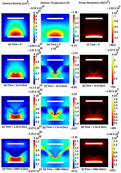
Figure 1.
Distribution of electron, electron temperature, and power dissipation in plasma at different time steps: (a,e,i) initial moment, (b,f,j) 1 µSec, (c,g,k) 1.5 µSec and (d,h,l) 500 µSec after application of 20 mT ultrafast transverse magnetic field (UFTMF).
A net space charge appeared near the magnetized region, and so there would be a strong electric field compared to what existed in the neutral plasma medium. This electric field caused electrons to gain more energy. That is why there were high-temperature electrons as depicted in Figure 1e–h. Indeed, there was an increment in the electron temperature from 1.38 to 2.29 eV. These high-temperature electrons caused high reaction rates and high power dissipation in the plasma medium. Figure 1i–l shows the variations of power dissipation in plasma.
Electron flux and related streamlines have been illustrated in Figure 2. The trajectory of electrons was broken when electrons entered the magnetized region. If the magnetic field region contains contacts, what may happen in reality is a high electric field region that forms from the cathode to the anode. This instantaneous disturbance in the electron flux and consequently electron density and net space charge was responsible for the instantaneous extreme value of the electric field in the plasma medium and the increment in arc voltage.
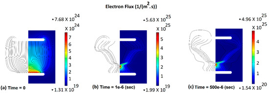
Figure 2.
Distribution of the electron flux at different time steps: (a) initial moment, (b) 1 µSec and (c) 500 µSec after application of 20 mT UFTMF.
Figure 3a shows the electric potential distribution across the central axis of the plasma chamber at different time steps 0, 1 µSec, 1.5 µSec, 30 µSec, and 500 µSec after application of UFTMF. As it can be seen in Figure 3a, there was a dramatic increment in arc voltage in a short time duration. Actually, arc voltage jumped from 5.9 to 10.1 V within 1 µSec. This instantaneous increment in arc voltage caused a transient voltage change with a rate of rise of 4.2 MV/sec. In this situation, a strong electric field region appeared near the magnetized region. The difference between the density of the electrons and ions, which was caused by the applied UFTMF, was responsible for this extreme electric field in the plasma medium. This region was about 3 mm from the cathode where there was an approximately zero electric field in the plasma medium before application of UFTMF. This strong electric field was the main reason for high-temperature electrons, high reaction rates, and the high power dissipation mentioned before.
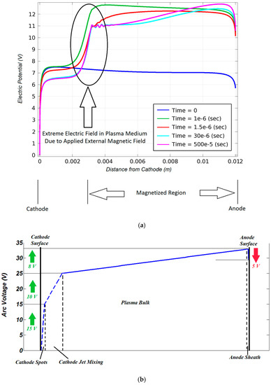
Figure 3.
(a) Distribution of the electric potential across the symmetry axis of the plasma chamber at time steps: 0 µSec, 1 µSec, 1.5 µSec, 30 µSec, and 500 µSec after application of 20 mT UFTMF. (b) Distribution of the electric potential from the cathode to the anode according to the 15 kA arc imposed by the axial magnetic field [6].
In Figure 3b, potential distribution along the arc axis in the diffuse mode arc with the current of 15 kA has been depicted [6], which is rarely mentioned in the literature. As illustrated in Figure 3b from the perspective of the potential distribution, the arc consists of four major regions: cathode spots, cathode jet mixing, the plasma bulk, and the anode sheath [6]. The considered model for the diffuse mode vacuum arc in the present paper had mathematically modeled only three regions: cathode jet mixing, plasma bulk, and anode sheath because the focus was on what happened in plasma due to UFTMF and mechanisms of forming and extinguishing of cathode spots was not considered. Another issue in this paper is the level of the arc current. A voltage drop along the plasma bulk region was proportional to the arc current. Thus, a voltage drop of 8 V for the arc current of 15 kA in Figure 3b will disappear in Figure 3a. By this description and comparing Figure 3a,b, it can be seen that if the voltage drop across the cathode spot region and plasma bulk was neglected from Figure 3b, there would be a trend similar to what has been presented in Figure 3a at “Time = 0” and this similarity validates the physical model, which was used in this paper.
Observation of such a high rate of rise in arc voltage, 4.2 MV/sec, illustrates the idea that a higher value UFTMF will give a sufficient rate of rise in arc voltage to commutate the arc current to a parallel capacitor. Another simulation with 1 T UFTMF was performed to investigate this idea, and the results were as expected.
At the first step, no parallel capacitor was assumed in the circuit, and an UFTMF of 1 T was applied to the arc. An increment of 20 times in the arc voltage appeared, as shown in Figure 4.
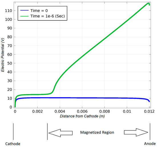
Figure 4.
Distribution of the electric potential across the symmetry axis of the plasma chamber at time steps: 0 and 1 µSec after application of 1 T UFTMF.
Figure 4 shows that the arc voltage increased from 5.9 to 117 V by the application of an UFTMF of 1 T within just 1 µSec. A value of the parallel capacitor as illustrated in Figure 5 was calculated by performing numerous simulations with a focus on the commutation of the arc current. Various values of the parallel capacitor were chosen and simulated simultaneously with a plasma analysis in a range of a few pF to several µF. An appropriate value for successful commutation was calculated as 200 nF.
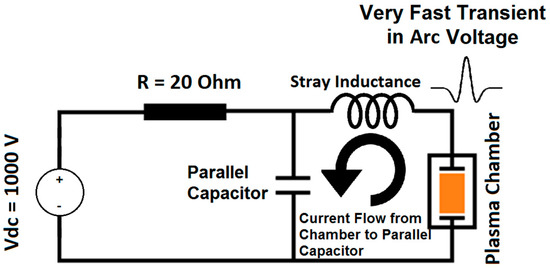
Figure 5.
The external circuit of the plasma chamber, which is equipped by a parallel capacitor.
As it is mentioned before, arc current commutation from the plasma chamber to the parallel capacitor will be considered as an interruption of the arc current if the interrupter is capable of a high-frequency current interruption. Waveforms of currents flowing through the arc and the parallel capacitor were calculated and depicted in Figure 6.
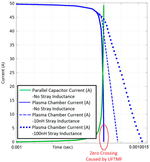
Figure 6.
Waveforms of the plasma chamber and parallel capacitor current after application of an UFTMF of 1 T. Successful commutation is achieved with the 200 nF parallel capacitor.
As it can be seen in Figure 6, a successful current commutation was achieved by placement of a 200 nF capacitor in parallel to the plasma chamber, where a zero-crossing in the arc current was observed. In the commutation process, the impedance of the parallel capacitor was much lower than the source side because of the high-frequency content of the arc voltage. The capacitor will charge up to a higher voltage than the initial arc voltage because of the direction of the electric current. By the charging process, the arc voltage will be restrained by the capacitor and a high arc voltage of 100 V as expressed in Figure 3 will not appear. Actually, the voltage of the capacitor scales up from 5.9 to 13.7 V. In addition, the effect of a stray inductance of the main circuit between the interrupter and parallel capacitor was considered for three values of 0, 10, and 100 nH. As depicted in Figure 6, by increment in stray inductance, a zero crossing time will occur with more delay and a zero crossing may be lost with large values of stray inductance. A design with a minimum value of stray inductance in this commutation system will be one of the key points.
The mentioned performance of this circuit under strong UFTMF expresses that successful interruption of the DC current will be accessible by this method while the transient recovery voltage across the interrupter will be limited by the parallel capacitor. There are, however, some technological issues, which have been discussed in the following.
4. Technological Discussions
Provision of UFTMF especially in medium-voltage power networks is the first challenge of this system. The main source of such high magnitude and an ultrafast magnetic field is a coil with the perpendicular axis to the current path. In addition, the coil should present a low value of inductance. In this system, there is a need to generate an ultrafast rising magnetic field, and consequently, there is a need to the ultrafast rising current in the coil. If the inductance of the coil is too high, the rise time of the current will increase, and UFTMF will not be accessible. The energy source to feed the coil may be a capacitor, which is charged to an appropriate voltage, and it can provide a sufficient amount of energy to increase the current in the coil. Capacitance and inductance of this system will satisfy the rise time of the electric current in the coil.
As illustrated in Figure 7, a two-turn coil was placed beside a VI. This coil was considered with two individual single turn coils on both sides of the VI, and the connecting path between two coils consisted of two symmetric parallel paths. These two parallel paths ensured the transverse magnetic field with the minimum axial component.
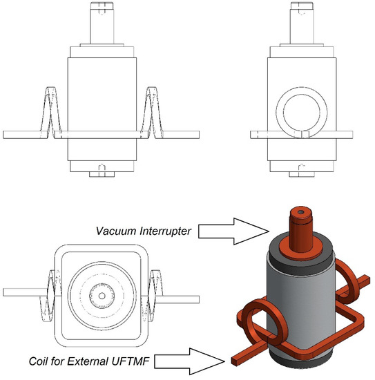
Figure 7.
A vacuum interrupter (VI) equipped with an external UFTMF coil.
An electric current of 200 kA with a rise-time of 1 µSec flowing through the coil ensured UFTMF with a rate of rise of 106 T/sec.
Distribution of the magnetic flux density and related arrow-lines inside the arcing medium of VI has been depicted in Figure 8 for the mentioned coil current and by the use of a finite element simulation.
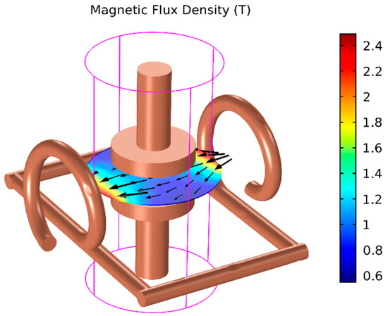
Figure 8.
Distribution of the magnetic flux density amplitude generated by an electric current of 200 kA with 1 µSec rise-time.
A charged capacitor, which is capable of providing pulsed current to the coil, will be an appropriate choice of energy source for this system. The capacitance and charging voltage of the capacitor can be determined by knowing the inductance of the coil. Finite element simulation of the coil and calculation of the magnetic field and magnetic energy distribution expressed that the inductance of the coil was 0.2 µH. The capacitance and charging voltage of the capacitor were calculated by considering an inductance value of 0.2 µH, a peak current of 200 kA, and a rise time of 1 µSec. The calculated capacitance was 2 µF and the charging voltage was 60 kV. These values satisfied the necessary electric current for the coil to reach the mentioned criteria. A schematic diagram of the feeding circuit is depicted in Figure 9.
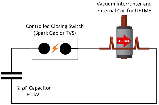
Figure 9.
Schematic diagram of an electric current feeding circuit.
As illustrated in Figure 9, a closing switch capable of passing 200 kA is required. Possible candidates could be controlled spark gap closing switches or triggered vacuum switches (TVS). The breakdown voltage of the gap can be controlled by gap distance and gas pressure of the spark gap [21,22].
One of the big challenges in this technology is penetrating the magnetic field into the arc chamber. Electric contacts of VI and the switching gap are surrounded by the vapor shields [23]. According to the electromagnetic theory, it is expected that UFTMF will be damped by the metallic vapor shields because of its high-frequency content and as a consequence of large induced currents inside the shield. Conventional vapor shields act as a perfect electromagnetic shield for such UFTMF and so magnetic field damps dramatically inside the shield. This problem should be addressed by changing the structure of the vapor shield. One possible approach to resolve this problem is the replacement of the arc shield with a similar one with a different material. The use of one-piece ceramic vacuum interrupters as suggested in [24] could be considered in this context. The tolerable amount of a metal coating on an isolating material (e.g., due to the deposition of metal vapor on the ceramic shield) is dependent on the frequency range of UFTMF. Since the highest frequency content of UFTMF is 500 kHz, a coating layer of 10–20 µm will be completely transparent to the UFTMF. In addition, the challenge may be overcome by making specific cut-lines on the vapor shield and using an overlapping structure.
5. Conclusions
The system proposed in this paper can be an innovative concept to introduce new technology for HVDC circuit breakers and fault current limiters. Imposing an UFTMF with the magnitude of 1 T and the rise time of 1 µSec or less to a modified commercial VI led to a considerable disturbance in charged particles’ spatial distribution and consequently to a transient increment in arc voltage. The electric current of VI will be commuted successfully to an appropriate parallel capacitive external circuit, and a zero-crossing in the electric current of VI will be achieved. All of these results were calculated by the finite element method based simulation of copper vapor plasma in VI while the interaction of plasma and UFTMF was considered.
This concept of current interruption introduces an alternative method for the interruption of electric currents when there is no zero-crossing, or there is a long delay time in reaching the zero-crossing. DC current in the HVDC power network and AC current of generators in the HVAC power etwork are the main cases of these applications. Another application of the proposed system is in the HVAC power network where there is a need to have an immediate current interruption. Fault current limiters are the main examples of this situation.
The main technological issues—provision of UFTMF, feeding circuit, and penetration of UFTMF into contact area of VI—were discussed. This novel method will definitely encounter other technological limitations such as necessary variations in the structure of VI, contact surface treatment for the better high-frequency current interruption, UFTMF positioning, etc. Thus, the presented results of this paper call for future experimental validations.
Author Contributions
Conceptualization, E.H. and K.N.; methodology, E.H. and K.N.; software, E.H.; validation, E.H.; formal analysis, E.H.; investigation, E.H. and K.N.; resources, E.H.; writing—original draft preparation, E.H.; writing—review and editing, E.H. and K.N.; visualization, E.H.; supervision, K.N.; funding acquisition, K.N. All authors have read and agreed to the published version of the manuscript.
Funding
This research received no external funding. The Article Processing Charges (APC) was funded by NTNU.
Conflicts of Interest
The authors declare no conflict of interest.
References
- Slade, P.G. The Vacuum Interrupter, Theory, Design, and Application; CRC Press: Boca Raton, FL, USA, 2008. [Google Scholar]
- Garzon, R.D. High Voltage Circuit Breakers: Design and Applications, 2nd ed.; Marcel Dekker: New York, NY, USA, 2002. [Google Scholar]
- Niayesh, K.; Runde, M. Power Switching Components, Theory, Applications and Future Trends; Springer: Berlin/Heidelberg, Germany, 2017. [Google Scholar]
- Boxman, R.L.; Goldsmith, S.; Izraeli, I.; Shalev, S. A Model of multicathode-spot vacuum arc. IEEE Trans. Plasma Sci. 1983, 11, 138–145. [Google Scholar] [CrossRef]
- Keidar, M.; Beilis, I.; Boxman, R.; Goldsmith, S. Potential and current distribution in the interelectrode gap of the vacuum arc in a magnetic field. In Proceedings of the XVIIth International Symposium on Discharges and Electrical Insulation in Vacuum, Berkeley, CA, USA, 21–26 July 1996; pp. 146–150. [Google Scholar]
- Schade, E.; Shmelev, D. Numerical simulation of high-current vacuum arcs with an external axial magnetic field. IEEE Trans. Plasma Sci. 2003, 31, 890–901. [Google Scholar] [CrossRef]
- Shmelev, D.; Delachaux, T. Physical modeling and numerical simulation of constricted high-current vacuum arcs under the influence of a transverse magnetic field. IEEE Tran. Plasma Sci. 2009, 37, 1379–1385. [Google Scholar] [CrossRef]
- Dullni, E.; Schade, E.; Shang, W. Vacuum arcs driven by cross-magnetic fields (RMF). IEEE Trans. Plasma Sci. 2003, 31, 902–908. [Google Scholar] [CrossRef]
- Chaly, A.; Logatchev, A.; Zabello, K.; Shkol’nik, S. High-current vacuum arc appearance in nonhomogeneous axial magnetic field. IEEE Trans. Plasma Sci. 2003, 31, 884–889. [Google Scholar] [CrossRef]
- Zabello, K.; Barinov, Y.; Chaly, A.; Logatchev, A.; Shkol’nik, S. Experimental study of cathode spot motion and burning voltage of low-current vacuum arc in magnetic field. IEEE Trans. Plasma Sci. 2005, 33, 1553–1559. [Google Scholar] [CrossRef]
- Emtage, P.; Kimblin, C.; Gorman, J.; Holmes, F.; Heberlein, J.; Voshall, R.; Slade, P. Interaction between vacuum arcs and transverse magnetic fields with application to current limitation. IEEE Trans. Plasma Sci. 1980, 8, 314–319. [Google Scholar] [CrossRef]
- Franck, C.M. HVDC circuit breakers: A review identifying future research needs. IEEE Trans. Power Deliv. 2011, 26, 998–1006. [Google Scholar] [CrossRef]
- Jadidian, J. A compact design for high voltage direct current circuit breaker. IEEE Trans. Plasma Sci. 2009, 37, 1084–1091. [Google Scholar] [CrossRef]
- Hashemi, E.; Niayesh, K.; Mohseni, H. Effect of transverse magnetic field on low-pressure argon discharge. Turk. J. Electr. Eng. Comput. Sci. 2016, 24, 4957–4969. [Google Scholar] [CrossRef]
- Hagelaar, G.J.M.; Pitchford, L.C. Solving the Boltzmann equation to obtain electron transport coefficients and rate coefficients for fluid models. Plasma Sources Sci. Technol. 2005, 14, 722–733. [Google Scholar] [CrossRef]
- Bellan, P. Fundamentals of Plasma Physics; Cambridge University Press: Cambridge, UK, 2008. [Google Scholar]
- Bird, R.; Stewart, W.; Lightfoot, E. Transport Phenomena, 2nd ed.; Wiley: New York, NY, USA, 2002. [Google Scholar]
- Kee, R.; Coltrin, M.; Glarborg, P. Chemically Reacting Flow Theory and Practice; Wiley: New York, NY, USA, 2003. [Google Scholar]
- Neufeld, P.; Janzen, A.; Aziz, R. Empirical equations to calculate 16 of the transport collision integrals for the Lennard-Jones potential. J. Chem. Phys. 1972, 57, 1100–1102. [Google Scholar] [CrossRef]
- Tkachev, A.N.; Fedenev, A.A.; Yakovlenko, S.T. Townsend coefficient, escape curve and fraction of runaway electrons in copper vapor. Laser Phys. 2007, 17, 775–781. [Google Scholar] [CrossRef]
- Williams, P.F.; Peterkin, F.E. Gas Discharge Closing Switches; Plenum Press: New York, NY, USA, 1990. [Google Scholar]
- Niayesh, K.; Hashemi, E.; Agheb, E.; Jadidian, J. Subnanosecond breakdown mechanism of low-pressure gaseous spark gaps. IEEE Trans. Plasma Sci. 2008, 36, 930–931. [Google Scholar] [CrossRef]
- VD4 Medium Voltage Vacuum Circuit Breakers Technical Catalog; Rev. X; ABB Inc.: Zurich, Switzerland, 2018.
- Falkingham, L.T. The design and development of the shieldless vacuum interrupter concept. In Proceedings of the 22nd International Symposium on Discharges and Electrical Insulation in Vacuum, Yalta, Ukraine, 27 September–1 October 2004; pp. 430–433. [Google Scholar]


© 2020 by the authors. Licensee MDPI, Basel, Switzerland. This article is an open access article distributed under the terms and conditions of the Creative Commons Attribution (CC BY) license (http://creativecommons.org/licenses/by/4.0/).