Article

Analysis of the Thermal Retrofitting Potential of the External Walls of Podhale’s Historical Timber Buildings in the Aspect of the Non-Deterioration of Their Technical Condition

by
Małgorzata Fedorczak-Cisak
1,*,
Elżbieta Radziszewska-Zielina
1,
Bożena Orlik-Kożdoń
2,*,
Tomasz Steidl
2 and
Tadeusz Tatara
1
1
Faculty of Civil Engineering, Cracow University of Technology, 31-155 Cracow, Poland
2
Faculty of Civil Engineering, Silesia University of Technology, 44-100 Gliwice, Poland
*
Authors to whom correspondence should be addressed.
Energies 2020, 13(18), 4610; https://doi.org/10.3390/en13184610
Submission received: 13 July 2020 / Revised: 28 August 2020 / Accepted: 31 August 2020 / Published: 4 September 2020
(This article belongs to the Special Issue Energy Performance of Buildings)

Abstract

:
The paper discusses thermal quality improvement in historic buildings. It is based on a case study of a wooden historical building in an architectural style typical of Zakopane, located in the Podhale region of Poland. The building’s historical value and timber structure prevent the application of typical thermal retrofitting solutions. This paper presents an analysis of the possibilities of the improvement of energy performance of a historic building (villa) which included: a review of the available energy performance improvement solutions applicable to this type of building, with a particular focus on applying internal insulation; a technical condition assessment using non-invasive methods, the identification of problematic areas in terms of the thermal retrofitting of buildings with timber walls and decks; in situ tests: thermovision tests which showed the places with temperature distribution field disturbances in the building’s envelope, focusing on thermal bridges; measurements of actual thermal transmittance coefficients for extant partitions; measurements of the building’s airtightness and the microclimate in selected rooms; numerical analysis: an assessment of the influence of the thermal bridges on the building’s existing condition, an analysis of water content changes in wall systems post-insulation. The presented approach enables the improvement of the energy performance of timber historical buildings while preserving the historical value of its architecture. It is innovative because it tries to fill in a research gap concerning a lack of relevant guidelines in Poland. The research questions that the authors asked were as follows. Is it possible to improve the thermal insulation of a building’s wooden walls without adversely affecting the building’s technical condition? With regard to the necessity to meet nZEB (nearly zero energy building) standards, is it feasible to improve the timber walls of historical buildings? The study found that under the correct assumptions and while maintaining a responsible approach to design, it is possible to improve the energy performance of historical buildings without interfering with historical heritage.

Graphical Abstract

1. Introduction

In a period of sustainable development and energy conservation, it is beneficial to look for areas in which to improve energy performance. This is particularly essential in sectors with the highest energy consumption indicators, such as construction [1]. The profitability of a given construction project and its occupancy costs depend on the adopted technical solutions [2,3]. Directive 2002/91/WE on the energy performance of buildings [4] initiated an energy-focused revolution in the construction sector, defining broad major objectives and assumptions aimed at lowering the energy consumption of buildings. An amended version of the Directive, published as Directive 2010/31//UE, [5] introduced a new standard of buildings: the nearly zero-energy building, which shall apply to all European Union member states after 2021. This standard is defined in Polish regulations [6] as applicable to newly-designed buildings and those subjected to energy retrofitting (historic buildings being exempted). As stipulated in Article 5 of the Polish Construction Law Act [7] buildings protected under the Monuments Protection and Preservation Act are practically exempted from legal requirements concerning thermal insulation. In most cases, the technical condition of historic buildings and those under conservation is either poor or very poor [8,9,10].
The problem of non-compliance with conservation guidelines and the resulting poor technical condition of historic buildings displaying different construction solutions was presented in [11,12]. From a developer’s point of view, knowledge about the adaptive reuse potential of a historic building and the cost of renovation projects is a key issue [8,13,14]. The authors of this paper wanted to determine how to improve the energy standard of historic buildings while preserving their value as elements of historic heritage without adversely affecting their technical condition, and whether it is feasible to improve the thermal insulation of their partitions to levels compliant with nZEB standards (as required by some thermal retrofitting subsidy programmes for existing buildings, including historic ones). The latest version of Directive 2018/844 on the energy performance of buildings [15] states: “Research into and the testing of new solutions for improving the energy performance of historical buildings and sites should be encouraged, while also safeguarding and preserving cultural heritage.” This is a clear indication that we should pursue solutions towards improving the technical condition of historic buildings while also improving energy performance and maintaining respect and facilitating the preservation of national heritage. Apart from the guidelines referring to the improvement of the thermal performance of buildings, the directive also covers the aspects of ensuring proper indoor climate parameters: “(…) the demand for energy (…) is calculated in order to optimize health benefits, good air quality inside a building and comfort according to the required levels set by member states at the national and regional level” [15]. The issues of the quality of the internal environment of buildings were discussed in articles [16,17].
The Polish historic monuments register, section ‘A’, lists works of architecture and civil engineering [18]. They have been built throughout history, primarily using masonry and timber construction technology and are often still in use [19]. In this paper, the authors present their research and analyses of the energy performance improvement potential of a historic villa located in Zakopane, Poland. Zakopane is a mountain resort with the harshest climate conditions in Poland, which is why alleviating heat loss in the building is critical. The building in question, the Stara Polana villa, is a typical example of nineteenth-century health resort architecture, typical for Polish mountain resorts. It is built in a distinct, native architectural style, typical of timber guest houses and villas, which was first developed by Stanisław Witkiewicz, and continues to be applied. Podhale’s villas (Podhale—a region of the Polish Carpathian Mountains), often in an unaltered state, are used as housing, accommodation or arts galleries. The Stara Polana villa is currently a hostel (in the past it hosted an art gallery for artwork made by employees of the Cracow University of Technology). The management of the Cracow University of Technology plans to change the form of use of the building.
In [20,21,22] the authors explored new possible forms of use for this historic villa. A high-class hotel, a gallery and a conference centre were considered. In each case, it would be necessary to improve the villa’s technical condition, particularly the state of its internal walls and perform procedures that would allow a reduction in heating/cooling costs while improving comfort of use and safety [23]. To obtain a thermal retrofitting subsidy, it would be necessary to bring the thermal insulation of the partitions of the building up to par with the requirements of the owner. In this paper, the authors analyse the possibility of thermally retrofitting the external walls of the Stara Polana villa without adversely affecting its technical condition. This paper also proposes innovative solutions in improving the energy performance of historic buildings with a wooden structure.
The proposed solutions were developed on the basis of an innovative, original method. It was based on determining the actual technical condition of the building via a series of on-site tests, which included thermovision diagnostics, building envelope airtightness testing and determining envelope U heat transfer coefficients. The data collected during testing were used for further numerical analyses. This original approach is innovative since historic buildings often lack complete technical documentation and there are no research standards as to determining the actual effectiveness of their thermal insulation. Furthermore, the parameters of historic wooden walls deteriorate over time. The proposed on-site diagnostics method allowed to diagnose the actual condition of the building.

1.1. Overview of Historic Wooden Buildings in the Podhale Region

The style of Zakopane’s historic villas was based on a transformation of the vernacular Podhale cabin into a “Polish building capable of satisfying the most complex and sophisticated needs for comfort.” Witkiewicz is assumed to have been the precursor of the style, but names such as Dembowski, Martynowski, Prus or Sygietyński are also mentioned. As a basis, Witkiewicz used traditional architecture of the Podhale Gorals, enriching it with elements of the Secession. Zakopane’s villas are characterised by a wooden, log-based structural system and original décor and furnishing, which is a folk variation of the national style. The prime of the Podhale style is dated to the turn of the twentieth century. The primary material used for the construction of buildings in this style was wood, which was used for their walls and roofs, as well as stone, which was used to build foundations, bases or retaining walls [24]. The villa analysed by the authors also represents this style. It was built in 1905 for the Płaza family.
The building was built by budarz Jan Ustupski-Kubecek. In 1976, the Cracow University of Technology bought the villa from Stanisław Płaza. In the years 1978–1998, it housed the Regional Studio, established and supervised up to 1992 by Professor Stefan Żychoń [25]. Between 2000 and 2010, the building hosted the ‘Stara Polana’ gallery of the Cracow University of Technology, which exhibited works by artists from the Zakopane community, Cracow-based artists associated with the Cracow University of Technology, students, as well as artists with special needs. Since 2010, the villa has been operating as a hostel. At the time of writing this paper, the building was in a poor technical condition and required thorough renovation. The management of the Cracow University of Technology made a decision to improve the building’s state, including its thermal protection, and to adapt it to a different form of use. The new forms of use under consideration include a high-class hotel, a gallery or a conference and training centre [20]. Choosing any of these options requires a thorough improvement of the building’s technical condition [22].

1.2. Problems of the Thermal Retrofitting of Historic Buildings

The thermal retrofitting of historic buildings must always be a compromise between the improvement of the building’s technical condition and the unconditional preservation of cultural heritage. When engaging in energy retrofitting to be performed on a historical building, we should remember that all work must be focused on improving energy savings and ensuring a proper internal environment quality. When selecting thermal insulation materials and technologies for wooden walls, one should note that the historic substance of the building, including its facades, should not be interfered with. Obscuring historic facades using thermal insulation systems is not permitted. Internal thermal insulation, typically used in historic buildings, is problematic due to the problem of vapour condensation in the partition. It usually causes a decrease in the quality of the internal environment and it has negative effects on comfort of use.
Figure 1 shall present sample actual and saturated vapour pressure charts for the extant state of the building and vapour pressure for standard external thermal insulation (Figure 1a), and internal thermal insulation (Figure 1b). In the first case, there is no inter-layer condensation, while in the second, this problem can occur when materials are poorly paired. Both charts were prepared as an initial estimate, intended to analyse momentary inter-layer vapour condensation within a building partition as per PN-EN ISO 13788: 2013-05 [26]. In the authors’ opinion, this analysis does not provide a sufficient basis for design-stage action in the case of historic buildings that are to have internal insulation applied.

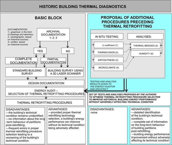
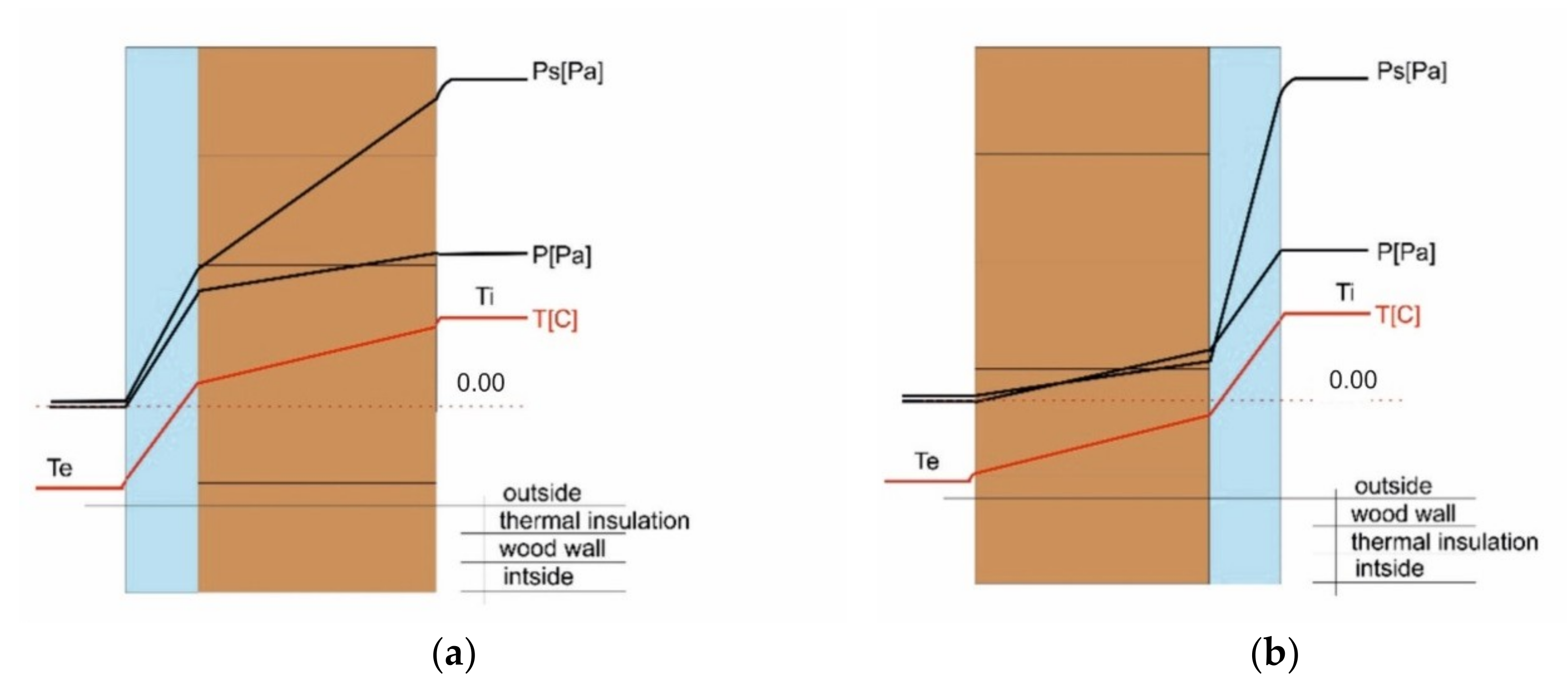
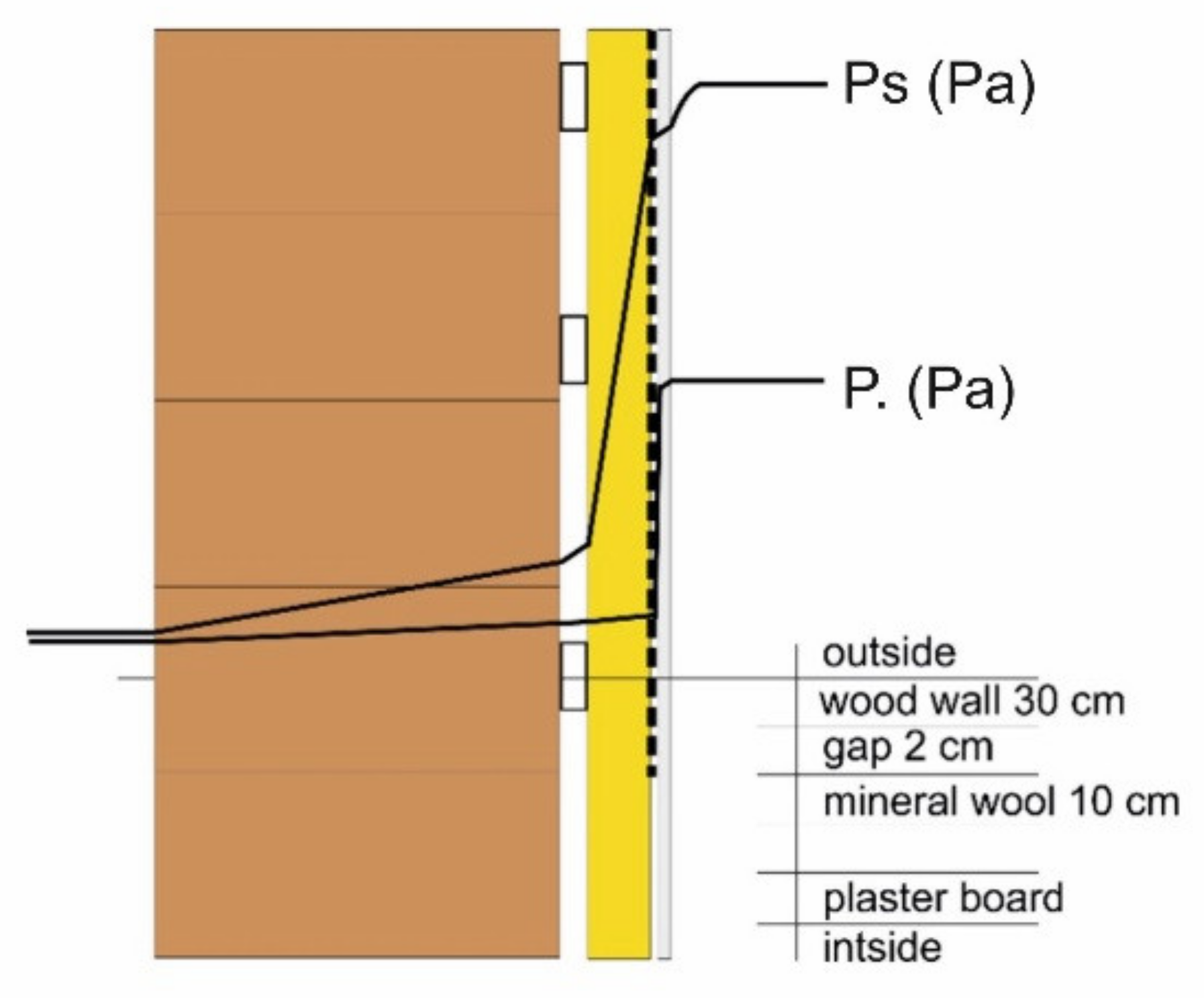
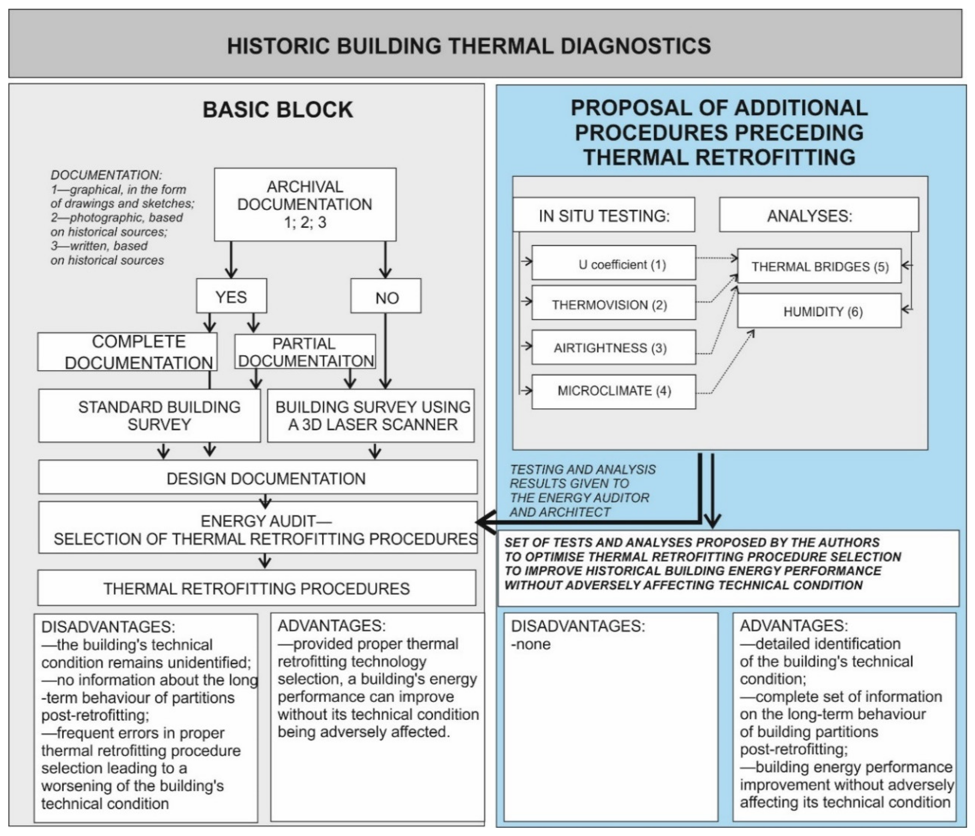
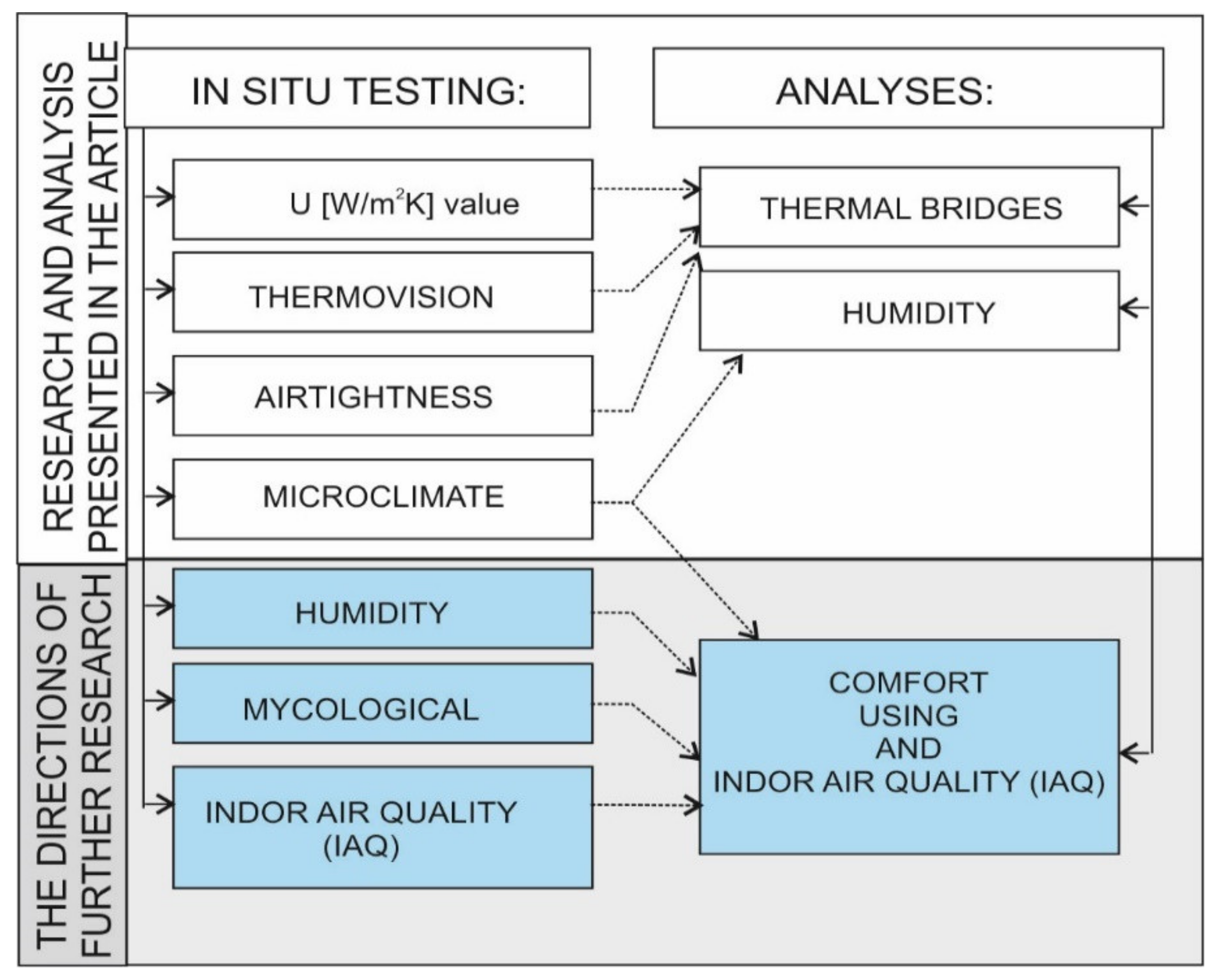
1.3. Methodology of Applying External Thermal Insulation

1.3.1. Indications for the Proposed Solutions

When using internal thermal insulation for walls, there are three main approaches:
  • Internal insulation that prevents condensation. The standard [27] recommends that the vapour diffusion thickness Sd of the applied thermal insulation should be greater than 1500 m.
  • Internal thermal insulation that minimises condensation. The DIN (Deutsches Institut für Normung) 4108-3 standard [27] allows the application of diffusion resistant materials, for which vapour diffusion thickness Sd is between 0.5 and 1500 m. It is unclear what impact such a large range of Sd values can have on the correctness of applied thermal insulation.
  • Internal insulation that permits condensation with proof that the condensate produced during the unfavourable period will evaporate over the course of a base year.
DIN 4108-3 [27] permits the use of materials with a diffusion resistance which have a vapour diffusion thickness Sd lower than 0.5 m. Thermal insulation materials used in such solutions display capillary activity and allow the accumulation of condensate within the material’s structure without worsening its physical properties.
Systems with internal vapour insulation work best in buildings with high indoor humidity. Due to the complete prevention of vapour diffusion through the surface, care should be taken to provide the highest possible ventilation effectiveness [28,29].
One of the distinct features of wooden walls is the presence of gaps between beams due to timber shrinkage, which allows the penetration of water from rainfall deep into the wall, a phenomenon described by Kozakiewicz [30,31], who described the associated aging processes and the slow loss of transverse cross-section surface of wooden elements. The properties of a wall in the context of rain protection are defined by their water absorption coefficients, the Sd vapour diffusion thickness and the product of these two values, CRP [32]. In 2009, WTA-Merkblatt 6-4 2009-05 [33] was published, which presents selected problems of internal thermal insulation design.
These solutions lead to a cooling of the wall’s structural section and thereby reduce the drying potential for the building’s existing structure. Internal thermal insulation reduces a wall’s accumulative properties, leading to faster temperature decreases, resulting in a high risk of condensation in the layer between the existing structure and the newly applied insulation. Both effects can lead to greater damp penetration of the wooden layer. The presented procedure allows a simplified (graphical) estimation of a given material solution’s correctness in the context of the water absorptivity of the existing partition and its external layer. The first element is determining the impact of rain on the wall’s external layer, i.e., determining its water absorptivity expressed as Ww kg/m2h0.5. Provided there is sufficient protection from rain compliant with DIN 4108 (part 3), it is typically sufficient. Otherwise, one should use the diagram below (Figure 2).
If the limit values and boundary conditions for Sd vapour diffusion resistance, the improvement in thermal insulation ΔR, and base capillarity/absorptivity are maintained, the condensate should not precipitate near the boundary layer between the old surface of the wall and the back side of the internal insulation (situations that can be detected using this simplified method are therefore practically devoid of condensation, as water is largely bound within the structural material). However, this means that wall structures in which condensation can occur cannot be analysed using the simplified verification method. Modern numerical methods are required in such cases. The scheme can only be used when:
  • the existing rainproofing solution of the facade is effective,
  • the existing external wall has a thermal resistance of at least RT ≥ 0.39 m2K/W,
  • the indoor climate is largely normal,
  • the average yearly temperature exceeds 7 °C, and resistance improvement ΔR should not exceed 2.5 or 2.0 m2K/W.
If any of these requirements is not met, high-precision analyses and calculations are required.

1.3.2. The Technical and Economic Aspects of Selecting an Internal Thermal Insulation System for Walls

The growing pressure to introduce sustainable building is associated with more rigorous requirements concerning the profitability and cost-effectiveness of a building’s construction, renovation and use, as well as limiting environmental impact [34]. In the case of selecting the technology for renovating a historic building, the decision cannot be based solely on an analysis of the renovation costs and choosing the cheapest alternative. The cost of using system-based internal thermal insulation materials can be several times greater than the cost of external system-based materials. Aspects that work in favour of internal insulation include avoiding the approval of a heritage conservator to cover a historic facade, which often features complex architecture. In the case of external insulation, one also needs to account for the cost and organisation of setting up a scaffolding on a large surface and the requisition of pavements. Applying internal insulation poses no such problems. Another key factor is the ability to conduct work regardless of weather conditions, which, in the case of a locality located in the vicinity of a tall mountain range, is not without significance. In the final cost balance, the difference between the external and internal insulation can prove to be not as drastic as it may initially appear. The internal wall insulation systems currently available on the market differ in terms of technical, technological and economic parameters. Some manufacturers dedicate specific systems to solving specific problems, e.g., in the form of panels preventing fungus and mould growth on the internal wall surfaces. When selecting a solution, the developer should account for a range of factors depending on their preferences, means, the building’s function, the number and complication of construction tasks. When analysing technical parameters during the design stage, one should keep in mind that some materials are more absorbent than others and are not suitable for application in cellars, where problems with damp can occur. Others still can have a lower compression strength, be brittle, and require greater care during transport, storage, processing, assembly and use.
Below is a presentation of a number of systems dedicated to internal wall insulation.
The most popular material used for the internal insulation of external walls is comprised of mineral insulation panels. They are made from a very light variant of aerated concrete. Their density is 115 kg/m3, which gives them high thermal insulation properties while retaining the major advantages of aerated concrete. The insulation panels are compliant with the ETA-05/0093 European Technical Assessment. It is a material with a high vapour permeability (μ = 3.0). The panels’ mechanism of action assumes the possibility of vapour condensation inside the panels during winter and drying during summer. The capacity to absorb vapour by the panels limits the phenomenon of precipitation occurring on the internal surface of the walls and the risk of mould development. The volume density of the panels is ρ < 115 kg/m3, while their thermal conductivity coefficient in a dry state is λ = 0.042 W/(mK), their diffusion resistance is μ = 3.0 [35]. Figure 3 shall present the general principle of the functioning of partitions insulated from inside using aerated concrete panels.
Another interesting solution is a system of internal insulation climate boards, which utilises calcium-silicate panels for the thermal retrofitting of and climate regulation in old and new buildings [36]. The panels are also intended to prevent water condensation and limit mould growth due to creating a highly base environment. This system uses mineral products, comprised of lime, quartz sand and water. It does not emit toxins and does not include substances prohibited from use in construction. In [37], the authors presented a positive comfort of use assessment for buildings which had thermal insulation applied from the inside using a lime-silicate system in the aspect of mould removal.
Polymer coatings with fillers and enhancing admixtures are also used to insulate partitions from the inside. The coatings include aerogel additions. The insulating components are typically aerogel and glass microgranules. The coatings improve and maintain a higher indoor thermal comfort due to reflecting heat and providing high thermal capacity. The use of this spackle affects wall surface temperature and lowers the amount of condensed vapour, particularly in corners and other places where surface temperature can fall below the dew point. The thickness of a single layer is between 0.8 and 1 mm. The principle of action, as stated by the manufacturer, is based on reflecting the heat stream and improving the thermal insulation properties of the partition. It ensures a V2 class water vapour permeability and is therefore average, while the thermal conductivity coefficient λ is 0.047 W/mK, and diffusion resistance is Sd = 0.19 m. The coating creates an anti-condensation layer on the wall surface. It thus protects the surface from excessive water condensation from the air and eliminates the causes of fungus and mould contamination. The lack of damp on the wall surface also increases the durability of the finish and improves the thermal insulation properties of the entire partition [38]. Studies performed by the Engineering and Research Institute of Construction in Prague on two geometrically identical rooms demonstrated that energy consumption for heating during the measuring period (4 days) in kWh while maintaining the same temperatures were 18% lower in the room that had such a coating applied to its internal walls. A beneficial impact on microclimate maintenance was also observed. The speed of heating the room from a temperature of 15 °C to 23 °C was 27% better in the case of rooms with a coating, while the cooling speed from a temperature of 23 °C down to 20 °C after shutting down the heating installation was lower by as much as 85% [38]. The technologies presented above are new. Time and testing are required to determine their impact on the structure of historic buildings. The simplest and traditionally most often used method is applying thermal insulation from the inside using mineral wool, which is separated from the wall by an air gap that allows the condensate to evaporate. Another method of countering water vapour penetration of the partition is the use of vapour barriers applied from the inside (Figure 4).
The approach suggested by the authors in this paper is innovative and novel for the improvement of energy performance of historic wooden buildings. There is a research gap in Poland concerning the lack of guidelines on the improvement of energy performance in these difficult structures. The lack of knowledge about the real conditions of historic buildings results in a situation in which the improvement of energy performance is based on assumed project data which is very different from their actual state. Over the years, historic buildings were used in various conditions. When one uses design data or data based on a rudimentary building survey, numerous mistakes can be made, worsening the building’s technical condition, indoor environment quality and comfort of use. The research question the authors wanted to answer was: How can the improvement of energy performance of historic buildings be optimised? Is there a difference between architectural design data and the data obtained via in situ examination and if so, then how significant is this difference? This is critical in the case of historic wooden buildings. Their wooden structural components desiccate and suffer damage from wear. In this paper, the authors present a novel approach to the process of the improvement of energy performance of historic buildings, by preceding standard thermal retrofitting procedures with the identification of the actual technical condition of structural partitions. The authors also incorporated microclimate analyses into the procedure, which is likewise a novel element as they are typically overlooked and ignored in modernisation case studies. Determining the actual conditions of historic buildings is the basis for numerical analyses which enable the selection of optimal energy performance improvement methods. The presented approach shall enable the selection of optimal methods of the improvement of energy performance of historic wooden buildings. Below, the authors present in Figure 5 a standard approach to thermal diagnostics of historic buildings and their proposal, significantly improving the standard procedure.
The scheme lists the tests proposed by the authors, which are discussed in greater detail further in the paper:
identification of the actual U heat transfer coefficient (1);
thermovision testing to diagnose qualitative defects in structural elements (2);
airtightness testing to identify air penetration of the building’s envelope (3);
microclimate testing (4).
All the proposed tests should form a basis for in-depth thermal (5) and moisture analyses (6) of historical building envelopes and analyse heat loss through thermal bridges. The findings, based on tests and analyses, which also show the actual condition of the historical building under analysis, shall form a basis for defining the scope of optimal thermal retrofitting procedures that are not to adversely affect the building’s technical condition or user comfort. Figure 1 also shows the advantages and disadvantages of the standard approach and the new method proposed by the authors.

2. Materials and Methods

2.1. Object of Study

The Stara Polana villa under study is in a poor technical condition. It has not been renovated since its construction. Its wooden walls are cracked, with observable gaps. The roof has no thermal insulation and the wooden structure of the building is not fully sealed from the external environment. The floor is laid without insulation on a clay base (pugging). The building is equipped with single-glazed windows with muntin bars that were observed to be leaky. The Stara Polana villa, which is currently a hostel, must be subjected to thermal retrofitting prior to its adaptive reuse. Based on analyses presented in [20], three new forms of use were proposed: a high-class hotel, a gallery and a conference centre. The analyses performed in [20] indicate that the best form of use for the building would be that of a conference and training centre. The building is comprised of two main parts: a timber section and a masonry section from field stones and brick. It has a full basement and a usable attic.
Building characteristics:
  • Footprint—304.74 m2
  • Usable floor area—641.33 m2
  • Volume—2805.95 m3
At present, the building is connected to a heating grid operated by Geotermia Podhalańska. The building’s walls are made of wooden beams with a thickness of 30 cm. In the masonry section, the walls have a thickness of 54 cm. The walls of the basement, which is partially below grade, are made of stone and their thickness varies (Table 1). The thermal transmittance values for each wall type of the building that were assumed for calculations are presented in Table 1. The timber walls showed signs of cracking across the entire thickness of the wall. They were examined according to the methodology presented in [39] to determine whether such large cracks could have been the result of vibrations caused by a nearby railway line. However, research has shown a minimal effect of vibration on damage to wooden walls. Cracks and marks are the result of the structural behaviour of wood and changes in humidity within its structure. The filler between the wooden beams is made from a ‘plait filler’, traditionally made from wood shavings.
In Table 1, U-values (W/m2K) for walls were calculated according to standard EN ISO 6946 [40]. Lambda parameters of the materials were taken from [41]. The thickness of the partitions is in accordance with the architectural documentation made available to the authors.
From the southeastern, frontal side, the building features large glazed surfaces with a gallery distinct for its architectural style. It has wooden, single-pane windows.
Due to the long period of the building’s use, its windows are no longer airtight and require replacement, subject to approval by the heritage conservator. Based on earlier experiences, it was assumed that the windows had a thermal transmittance of U > 3.50 W/(m2K), while double wooden doors had a high degree of wear—U > 3.80 W/(m2K). The building has a steep, wooden, hipped roof, covered with wooden shingles. It has no thermal insulation layer.
In this paper, the authors presented an analysis of the potential for applying thermal insulation to a wooden log wall with a thickness of 30 cm, bringing its thermal insulation to a standard required of nZEBs. The authors sought to answer the question of whether attaining a thermal transmittance value of U = 0.20 W/(m2K) (Polish requirement for nZEBs subjected to thermal retrofitting) by the external walls of the Stara Polana building was possible without leading to significant changes during later occupancy, preventing wall and wood damp, and for which technologies. The necessary and sufficient criterion was the condition of avoiding critical internal surface humidity, expressed by an appropriately high fRsi max indicator. It was assumed that the condition of attaining low wall U-values is a critical criterion for a developer who pursues obtaining a state subsidy for improving the energy performance of a heritage-listed building.
Attaining such a low value in the case of the presented system-based solutions requires that timber walls be insulated from the inside using layers with thicknesses as listed in Table 2. The technical data necessary for calculations were supplied by manufacturers.
Column 1 shows the calculated values of the thermal transmittance coefficient following standard EN ISO 6946 [40]. These are the values given for the option without insulation. The remaining columns show the values of the coefficient U for different types of insulation applied: W1—mineral wool, W2—PIR/PUR foam, W3—light aerated concrete, W4—silicate coating, W5—calcium silicate climate panels.
The thicknesses obtained via calculations result in the exclusion of the use of some systems due to practical considerations. In some systems, panels of such thicknesses are not used in internal insulation or the manufacturers simply do not produce panels that are this thick, which is why two or more panels would have to be glued together. Furthermore, a single panel of the system featured in alternative W5 with a thickness of 0.3 m would weigh 60 kg, which is a significant hindrance from the point of view of performing the thermal retrofitting and places additional load on the building’s structural system. The internal coating system also could not be applied due to the required thickness. Execution and organisation-related considerations are an important factor that affects technology selection decisions in the construction sector [42,43]. Technologies that allow the application of internal thermal insulation with a thickness that allows the attaining of U = 0.2 W/(m2K) include internal insulation using mineral wool and internal insulation using light aerated concrete panels. These technologies were selected for numerical analysis that shall be presented further in the paper.
In [20], the authors, who analysed the potential for improving the technical condition of the Stara Polana building in terms of selecting various different new forms of use for it, initially defined classes for heritage-listed buildings to be subjected to thermal retrofitting. The building classes, which depend on the improvement of their wall heat transfer coefficient, are presented in Table 3. In this paper, the authors assumed an improvement of the thermal insulation of the building’s walls to a value of U = 0.2 W/(m2K), (the level required of nZEBs subjected to thermal retrofitting in Poland). The current requirements for 2020 are: UC ≤ 0.23 W/(m2K). This means that the Stara Polana building would be assigned to class B using the classification proposed by the authors in [20].
The authors shall present their original and innovative method of analysing historic buildings based on on-site studies further in the paper. On-site studies were the basis for conducting the analysis of the potential to improve the thermal insulation properties of partitions without adversely affecting the historic building’s technical condition. The authors shall also present an analysis of whether it is justified for the thermal retrofitting of walls to achieve partition thermal insulation values compliant with nZEB requirements (Table 3—class B).

2.2. Research Method and Assessment of Thermal Protection

The technical condition of a building’s partition, thermal conductivity coefficients and airtightness all have a fundamental impact on energy performance. The authors propose the introduction of a new standard for the thermal retrofitting of historic buildings based on studies of their actual state, as observed on-site. The proposed testing procedure will allow high-precision analyses that can facilitate the lowering of energy consumption and estimating building partition behaviour after the application of the selected envelope thermal retrofitting procedures and, in the future, the assessment of the impact of these measures on indoor microclimate.
We propose the following course of action for assessing the thermal quality of wooden historic buildings, providing justification for each step:
  • Analysis of available construction documentation with a focus on thermal protection. Objective: supplement or recreate documentation, update it for the purposes of further action.
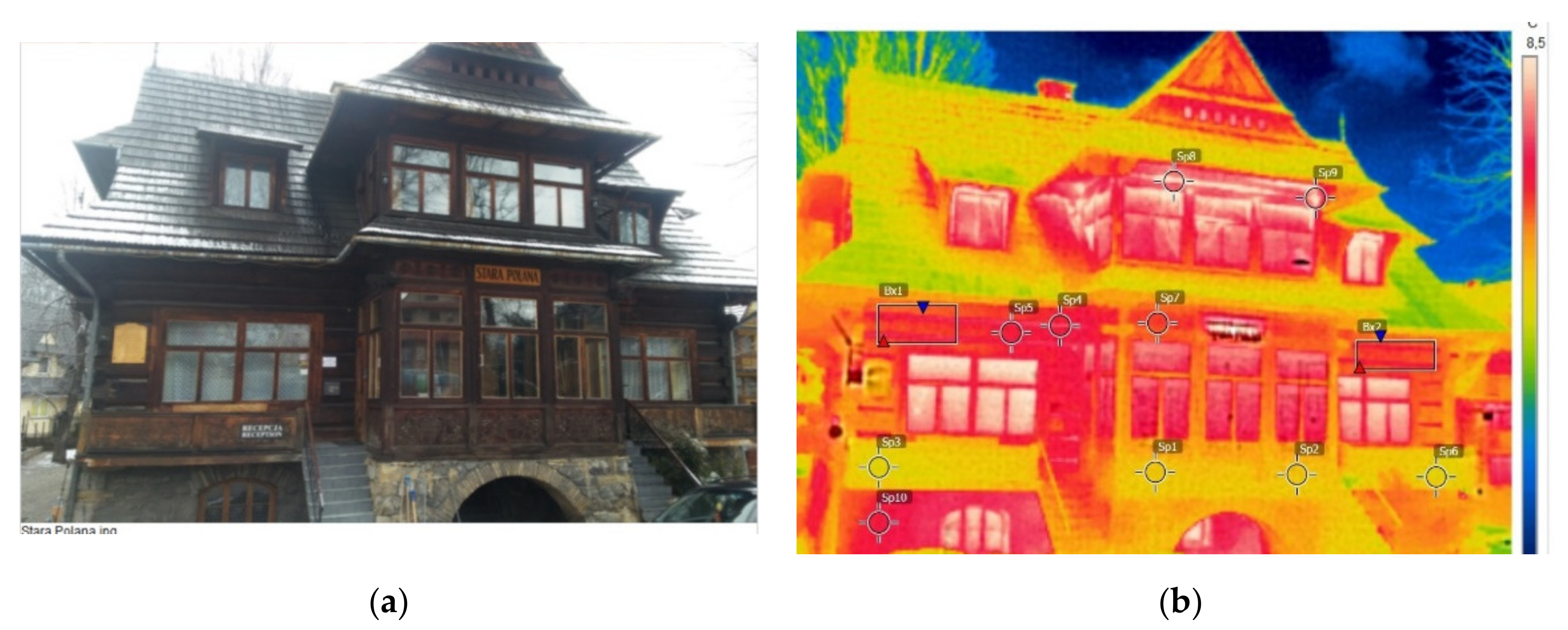
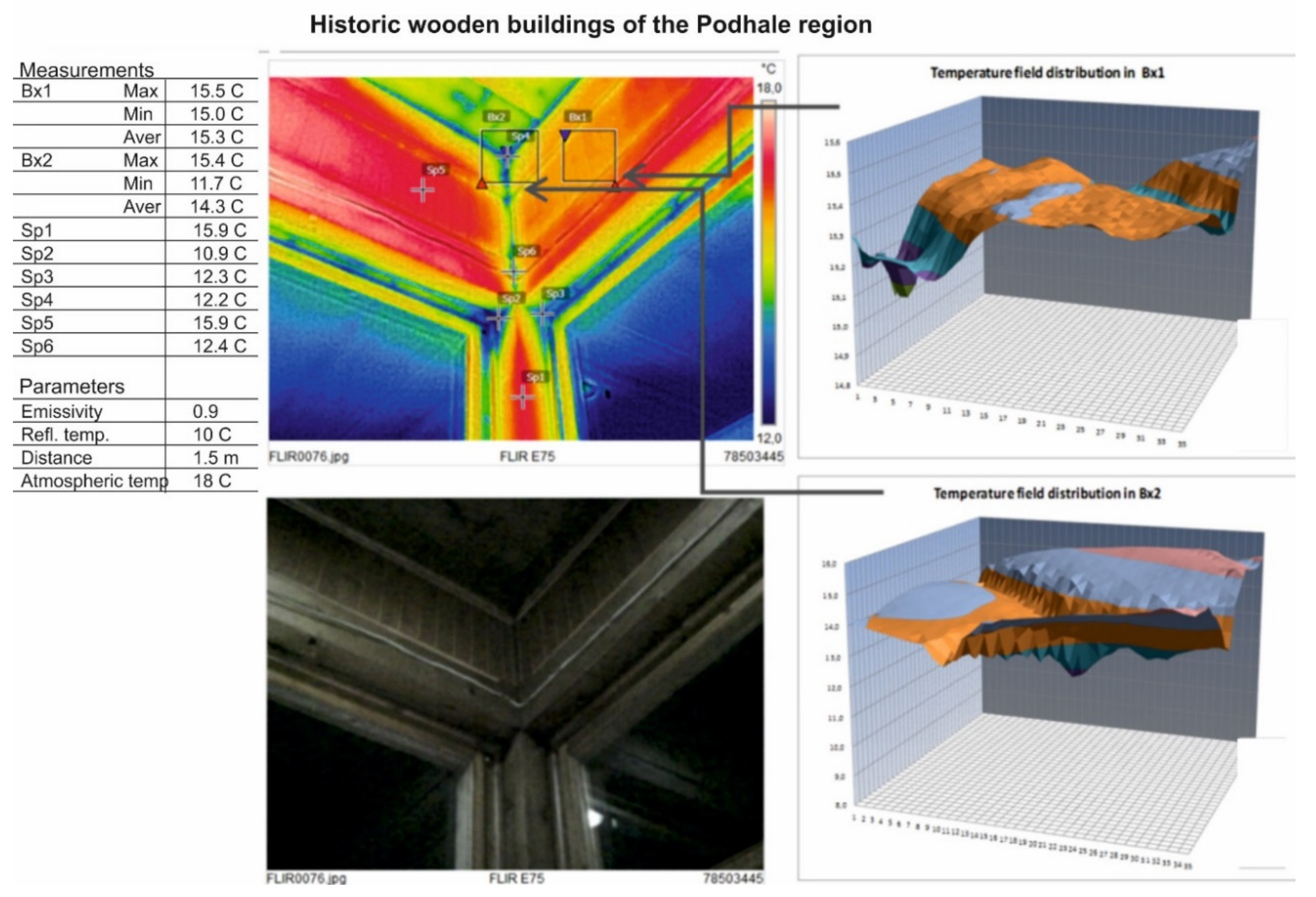
  • General study of the building during daytime, featuring the preparation of photographic and descriptive documentation. Objective: determine the building’s technical condition and the possibility of performing non-destructive testing in places displaying considerable wear or visible damage. Thermovision analysis of the entire building from the outside during nighttime in suitable atmospheric conditions. Objective: identification of places on the building’s facades showing significant heat leakage, preparation of documentation in the form of thermograms.
  • Detailed study of selected wall connections, places with identified linear and point thermal bridges, performed using thermal vision cameras. Objective: identification of the place of occurrence and geometric dimensions of thermal defects and anomalies, including airtightness breaches. Identifying thermal transmittance measurement sites.
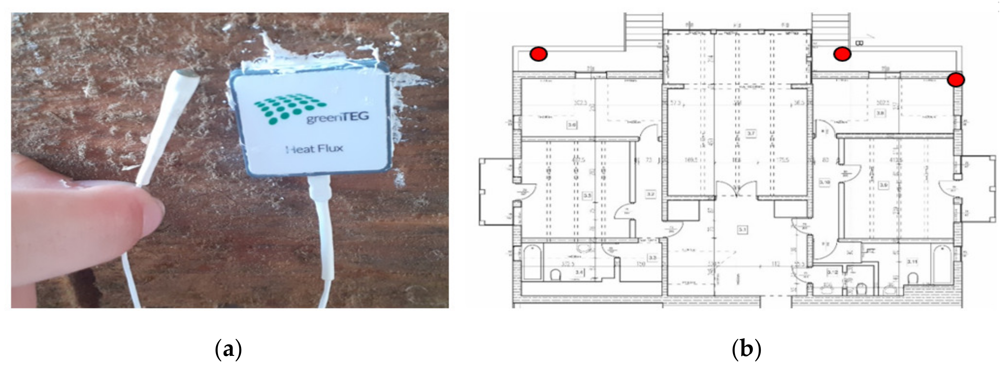
  • Thermal transmittance measurements using proper measuring equipment. Objective: identify the actual thermal transmittance of the envelope (walls).
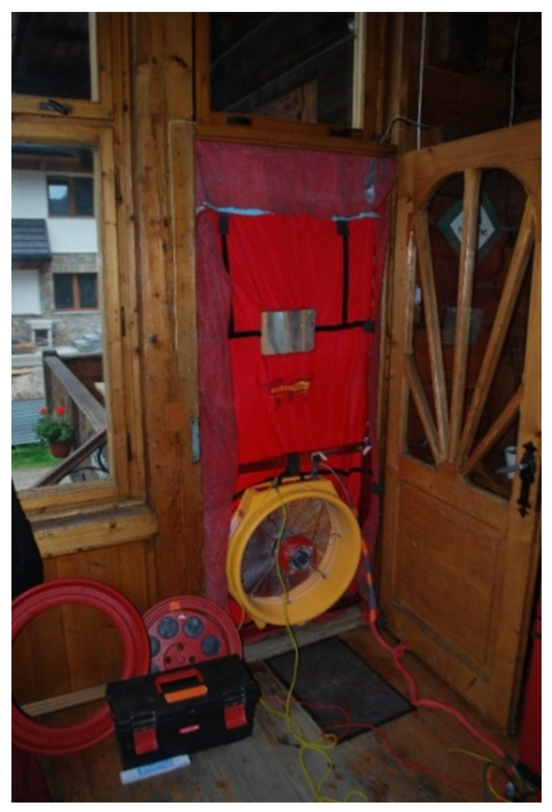
  • Airtightness testing of the building’s air penetration using a Blower Door measurement system. Objective: determine the actual air exchange rate for calculation purposes, confirm airtightness breach locations and their impact on heat loss within the building.
  • Indoor microclimate testing in selected spaces. Objective: collect data to account for the individual character of each space and its appropriate use in energy calculations and analyses using numerical simulation of water content changes in elements.
All of the tests are intended to result in preparing a dedicated renovation design, with a particular emphasis on improving thermal protection while maintaining historic elements and not allowing occupancy conditions to deteriorate.

2.2.1. Thermovision Analysis

Thermovision analysis—general analysis.
One of the elements of studying the thermal protection quality of the external walls of the Stara Polana building was a thermovision analysis of both the entire building from the outside and a detailed analysis of selected damaged areas from the inside. The methodology of qualitative thermovision analysis was outlined in the standard [44] and in [45,46,47]. The thermovision analysis was performed using a modern FLIR thermovision camera with a high thermal sensitivity of 0.06 °C. It has a display resolution of 320 × 240.
Weather conditions during the measurement:
  • The indoor air temperature was 22–26 °C; the outdoor air temperature was 2–3 °C
  • The relative indoor air humidity measured at a level of about 1 m above the floor was 40%. The wind speed was below 0.2 m/s. The sky was overcast when the measurement was taken.
  • The resolution of photos results from the technical parameters of the thermovision camera.
The thermograms were subjected to digital processing using a multispectral system (MSX) in reference to the selected places of the building under study.
As part of the general analysis of the building from the outside, around a dozen thermograms were made in compliance with all thermovision analysis requirements.
Figure 6 shows the front view of the building and its thermal imaging.

2.2.2. Building Envelope Airtightness Testing

The technical condition of a building’s envelope has a significant impact on its airtightness and thus on heat loss and comfort of use. Leaks in the building envelope affect energy savings and the air quality inside buildings. Heat loss caused by draughty windows can even reach 40% of the total energy consumption of a building [48]. According to the ordinance on the technical conditions that must be met by buildings and their placement [6], two levels of envelope airtightness are distinguished:
  • n50 ≤ 3.0 1/h for buildings with gravitational ventilation,
  • n50 ≤ 1.5 1/h for buildings with mechanical ventilation.
The general analyses performed on the building clearly indicated the need to perform airtightness measurements. The measurements were performed following the methodology outlined in ISO 9972:2015 [49]. The envelope airtightness analysis was performed using a pressure measurement method using the Blower Door device. The test was performed on 18 April 2019 at 13:00, under the following weather conditions: barometric pressure 91.95 kPa, wind strength 3 (weak breeze), external temperature 15 °C, internal temperature 19 °C. Figure 7 shows how to perform the envelope airtightness test.

2.2.3. Testing of the Actual Thermal Transmittance U

The tests were performed using the greeTEG system, composed of two temperature sensors (an internal and an external one), as well as a heat stream density sensor (Figure 8).
The placement of measurement stations was initially determined using prior thermovision analysis findings.
Sensor precision:
  • Internal/external surface temperature sensor ± 0.1 °C,
  • heat stream sensor ± 3%.
The measurement system determines the average thermal transmittance for the partition in compliance with EN 9869-1:2014 [50]. To perform valid measurements, the temperature difference between internal and external environment must be no smaller than 5 °C while the measurement time must be no shorter than 72 h.

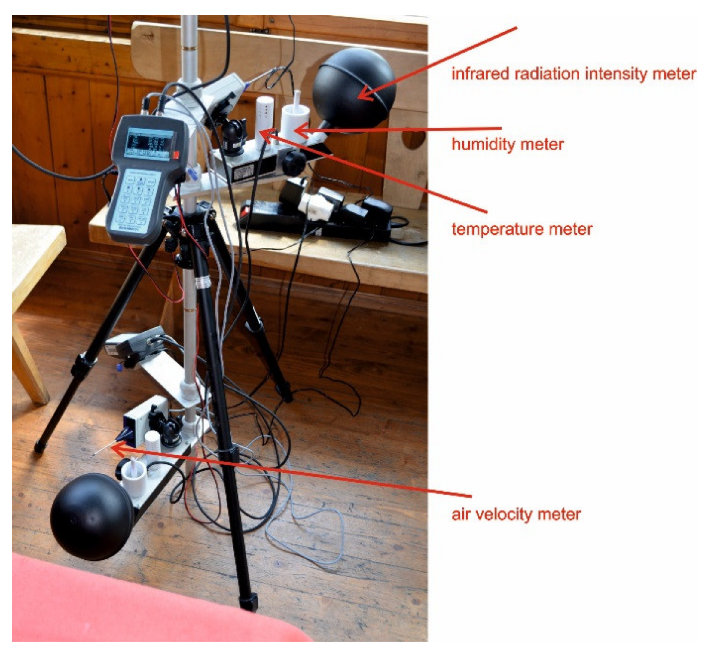
2.2.4. Indoor Microclimate Testing

Directive 2002/98/UE [4] highlights the fact that improving a building’s energy performance should also account for providing appropriate climate conditions (thermal comfort) inside the building. This subject is also discussed more widely in Directive 2018/844/UE [15]. The process of the improvement of energy performance, especially in historic buildings, should combine the improvement of energy savings with the quality of internal environment. The recommended criteria for internal environment properties including thermal comfort criteria are discussed in the new EN 16798-1 standard [51], which replaced standard EN 15251 [52]. Obviously, all comfort of use criteria must be met after the improvement of a building’s energy performance. This subject was widely analysed in [20]. Extensive information about thermal comfort and its analysis using Fanger’s method [53] was given in [54]. In this paper, the authors focused on determining internal microclimate conditions (measurements of temperature, moisture, infrared radiation, air velocity) that were actually present in the building. The results of the tests were used for further analyses.
The methodology for determining thermal comfort was based on the standard entitled PN-EN ISO 7730; Ergonomics of the thermal environment—Analytical determination and interpretation of thermal comfort using calculation of the Predicted Mean Vote (PMV) and Predicted Percentage Dissatisfied (PPD) indices and local thermal comfort criteria [55] (the standard was replaced by [52] and later by [51]). The measurement methodology was based on the PN ISO 7726 Ergonomics of the thermal environment—Instruments for measuring physical quantities standard [56]. The measuring equipment used was a microclimate metre (Figure 9). The height at which the measurement was taken was in accordance with standard 7726. The measurement was taken in the hall where users usually stand and for this reason the sensors were placed on three levels: at about 1.7 m, at about 1.1 m and at about 0.1 m above the floor. This information is given in the text in line 521 on page 14. The metrological performances of sensors are compliant with EN ISO 7726. The measurement device was placed in a guest room of the Stara Polana hostel. Clothing insulation was assumed at Iclo = 0.7 clo as a value for a transitory season and indoor clothing.
The data collected by measurement sensors is presented in Table 4.
The measured parameters were:
  • ta—air temperature;
  • tg—black globe temperature;
  • tnw—natural wet-bulb temperature;
  • RH—relative air humidity;
  • Va—air velocity.
On the basis of measurements, thermal comfort and local discomfort caused by draughts were calculated from Equations (1) and (2).
• PMV—Predicted Mean Vote
PMV = [0.303 · exp(−0.306 M) + 0.028] · ((M − W) − 3.05 10−3 [5733 − 6.99 (M − W) − pa]
−0.42 · [(M − W) − 58.15] − 1.7 10−5 M · (5867 − pa) − 0.0014 ·M · (34 − ta)
−3.96 · 10−8 · fcl · [(tcl + 273)4 − (tr + 273)4] − fcl · hc · (tcl − ta))
tcl = 35.7 − 0.028 · (M − W) − Icl{3.96 · 10−8 · fcl · [(tcl + 273)4 − (tr + 273)4] + fcl · hc · (tcl − ta)}
where:
  • M—metabolic rate (W/m2),
  • W—the density of energy loss in the form of mechanical work (W/m2),
  • Icl—clothing insulation (m2K/W),
  • fcl—clothing area factor (m2),
  • ta—air temperature (°C),
  • tr—mean radiant temperature (°C),
  • tcl—clothing surface temperature (°C).
DR = (34 − ta,l)(va,l − 0.05)0.62 (0.34va,l Tu + 3.14)
where:
  • ta,l—local air temperature °C,
  • va,l—average air speed m/s,
  • Tu—local turbulence intensity %.

2.3. Numerical Analyses

On-site testing formed the basis for numerical analyses intended to determine the possibility of improving the thermal insulation of external walls. The analysis was performed on an external wall made from wooden logs, with a thickness of 30 cm. The thermal and humidity analyses included an assessment of the extant and newly-designed partition in terms of:
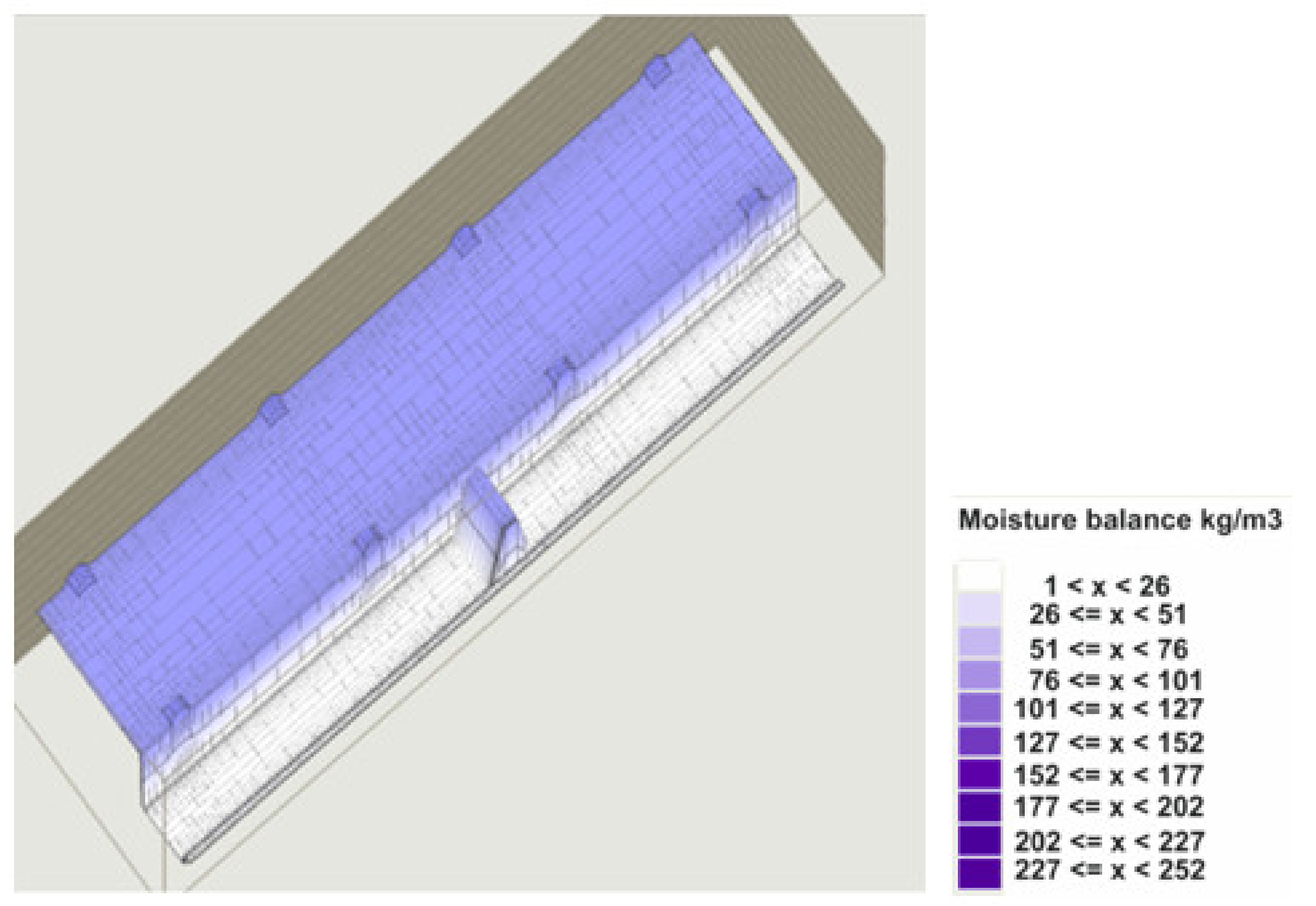
  • Condensation risk and water content increase within selected planes of the partition,
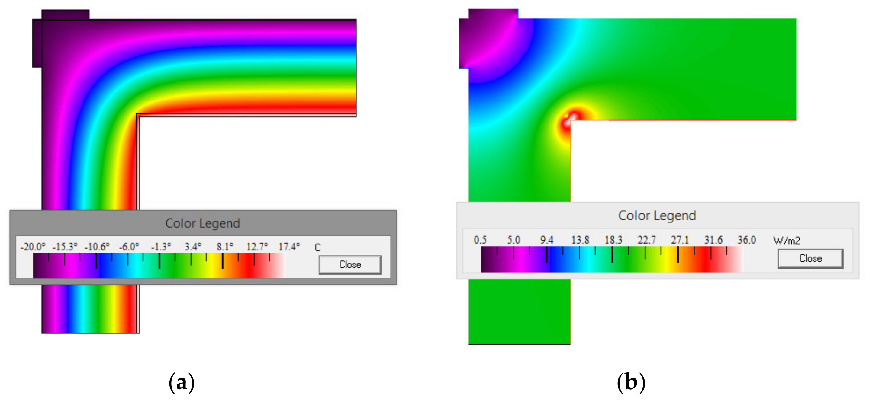
  • A selected thermal bridge by determining selected parameters that describe heat flow within areas of geometry shifts,
  • Risk of mould growth expressed by fRsi.
The analysis was performed for two thermal insulation alternatives, i.e., insulation materials in the form of light aerated concrete panels with a thickness of 12 cm and mineral wool with a thickness of 11 cm. The solution selection was determined by earlier assumptions as to the optimal thickness of the insulation material [27,57]. The characteristics of the materials are listed in Table 5. Thermal calculations along with a diagnosis of potential thermal bridges were performed using Therm 7.2. software. (Version 7.2, Lawrence Berkeley National Laboratory, Berkeley, CA, USA).
The analysis features a case of a thermal bridge in the form of a log wall corner featuring with thermal insulation applied from the inside using an insulation material with a thickness of 11 cm (in case of mineral wool). The calculations were performed following the assumptions presented in Table 5. Joint modelling was performed as per EN ISO 10211:2017 [58]. During the first stage of the testing, due to the non-uniform structure of the partition, a thermal transmittance value was calculated for an insulated and uninsulated variant of the wall.
To determine the correct design of the thermal bridge detail that would comply with applicable thermal and humidity requirements, detailed calculations of physical parameters were performed:
  • Linear thermal coupling coefficient L2D W/(mK),
  • Linear thermal transmittance coefficient determining additional heat loss due to linear thermal bridges Ψ W/(mK),
  • Temperature factor determined on the basis of minimal partition surface temperature at the site of the thermal bridge fRsi (-). The following qualities were accepted as boundary conditions: outdoor air temperature te: −20 °C, indoor air temperature ti: +20 °C, thermal surface coefficients he = 25.0 W/(m2 K), hi = 7.69 W/(m2 K), a fRsi hi = 4.0 W/(m2 K) value was assumed for calculations.
External environmental conditions were assumed as for the town of Zakopane. The microclimate conditions were assumed as per EN 15026 [59]—with a normal humidity load.

3. Results

3.1. Thermovision Analysis

The authors subjected the external wooden walls of the building and the joints of wooden elements with external walls, including window mounts, to high-precision analyses (Figure 10, Figure 11, Figure 12 and Figure 13).
Thermovision testing revealed a series of defects in the building’s envelope and near windows, including:
  • Airtightness breaches at points where external walls connected with wooden decks,
  • Airtightness breaches at points where wooden windows connect to the walls,
  • Lower thermal insulation at the joints between external wall beams (logs), seals in the form of a ‘plait’ woven from wood shavings were observed to have crumbled in some places. Slight cavities in the seals were observed,
  • No damp was observed on the thermograms and during macroscopic examination.
The distribution of the temperature field for typical joints of wooden elements in such buildings was presented on thermograms. The thermograms show the places where diagnostics is essential. The photos present the types of temperature field disturbances which are not signs of critical defects but thermal anomalies. The results are intended to draw attention to the fact that in the wooden buildings of Podhale region, the places indicated are usually where defects and anomalies occur simultaneously. It is recommended that each building should be assessed individually in places identified in the paper.
The authors attempted to use thermograms to calculate U heat transfer coefficients using the method outlined in [60], applying perturbation numbers. This action requires that the selected temperature distribution fields be uniform. Around a dozen precision thermograms were made so as to obtain a uniform temperature distribution field reading for a selected wall fragment. Below is a presentation of a selected external wall fragment for which the temperature distribution field appeared to be uniform. Afterwards, the selected element was subjected to a digital analysis. The average temperature deviation for the selected fragment was 0.4 °K. This was caused by the examined surface displaying both an actual and apparent temperature. Apparent temperature occurs in places where the material is not uniform, i.e., due to the presence of knots or wood discolouration.
The average deviation result for the temperature distribution fields under study convinced the authors to ignore the U thermal transmittance results obtained using this method. Other measurement methods are recommended in the case of examining wooden envelope elements, particularly in reference to historic buildings.

3.2. Results of Envelope Airtightness Tests for the Stara Polana Building

An airtightness test result for underpressure n50 = 10.09 (1/h) and overpressure n50 = 8.83 (1/h) was obtained for the Stara Polana building. These are atypically high values relative to those of standard newly-built buildings, for which the Ordinance concerning the technical conditions to be met by buildings and their placement recommends that, in the case of gravitational ventilation, envelope airtightness should not exceed n50 ≤ 3.0 1/h exchanges per hour. The value obtained from measurements confirmed the existence of severe airtightness breaches in the building’s envelope, which considerably affected its energy consumption.

3.3. Results of Determining the Actual U Thermal Transmittance for External Walls Made of Wooden Logs

The tests intended to determine the actual U thermal transmittance for the external walls made from wooden logs were performed between 23 March 2019 and 16 April 2019. Figure 14 shall present sample internal and external temperature measurements and a conversion U thermal transmittance for wooden log walls located on the ground floor of the Stara Polana building.
After initial fluctuations during the first days of measurement, the measured U thermal transmittance stabilised within the 0.60–0.65 W/(m2K) range. This value is around 30% greater than the value obtained via calculations (0.50 W/(m2K)). Due to a lack of a final stabilisation of the heat transfer coefficient, an additional high-precision method was used, which utilised data (temperature and heat stream density measurements) obtained from three measurement points.
This method is used to account for the effect of material thermal capacity. It can be used to analyse data that do not conform to the procedure of simple thermal resistance calculations.
For simple calculations, one uses the procedure in compliance with the Equation below (3):
R = j = 1 n T s i j T s e j j = 1 n q j
where:
  • R—partition thermal resistance calculated based on measurements W/(m2K),
  • Tsij—sequential temperature value measured on the internal surface of a partition °C,
  • Tsej—sequential temperature value measured on the external surface of a partition °C,
  • qj—sequential measured value of heat stream density W/m2.
To calculate the U coefficient for the external wall, the authors used a procedure that incorporates corrective coefficients. This method is based on using Fi and Fe corrective coefficients for the measured heat stream density values. As a result, in Equation (3), the sum Σqj is replaced by the expression below,
j = 1 n q j   F i δ T i + F e δ T e Δ t
where:
  • Δt is the time interval between measurements s,
  • δTi is the difference between internal temperature from the 24 h preceding the measurement and the internal average temperature for the first 24 h of measurements,
  • δTe—difference between internal temperature from the 24 h preceding the measurement and the external average temperature for the first 24 h of measurements,
  • Fi; Fe—correction coefficients calculated using Equations (5) and (6).
Corrective coefficients are calculated for each layer of the partition separately, using Equations (5) and (6), starting from the internal side, and are then summed so as to determine their total value as per Equation (7). It is required to either calculate or know the exact thermal resistance Rk for each layer Rk, the thermal capacity Ck of each layer and the thermal resistance R for the entire component. The exact calculation procedure is described in the standard [50].
F e k = C k R k R 1 6 + R i k + R e k 3 R + R i k R e k R 2
F i k = C k R e k R + R k 2 3 R 2 R i k R e k R 2
In addition, for each layer, one must calculate resistances on the internal (Rik) and external (Rek) side of the layer:
R i k =   j = 1 k 1 R j R e k =   j = k + 1 N R j
Correction coefficients for the entire element are thus given by:
F i =   k = 1 N F i k F e =   k = 1 N F e k
The thermal capacity for wood was assumed to be Ck = 1.25 MJ/m3/K.
After averaging measurement results, the authors obtained an actual thermal transmittance of U = 0.72 W/(m2K).
Accounting for the presence of linear and point thermal bridges, it can be assumed with a considerable degree of probability that the actual final U-value for wooden log walls is 0.75 W/(m2K).

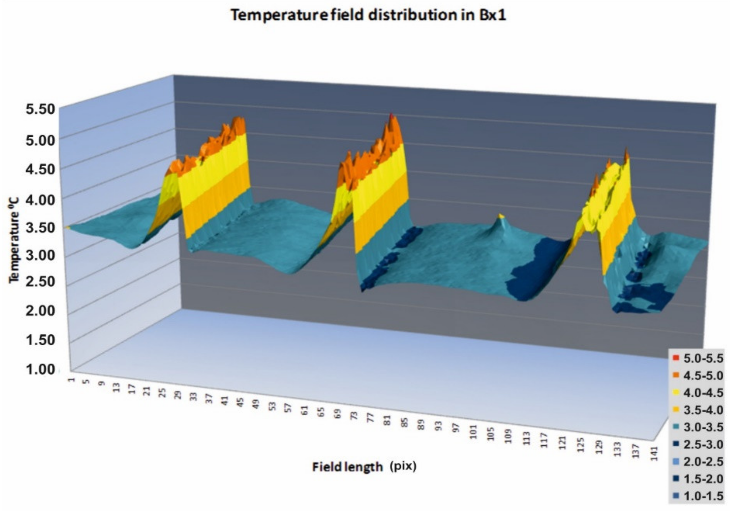
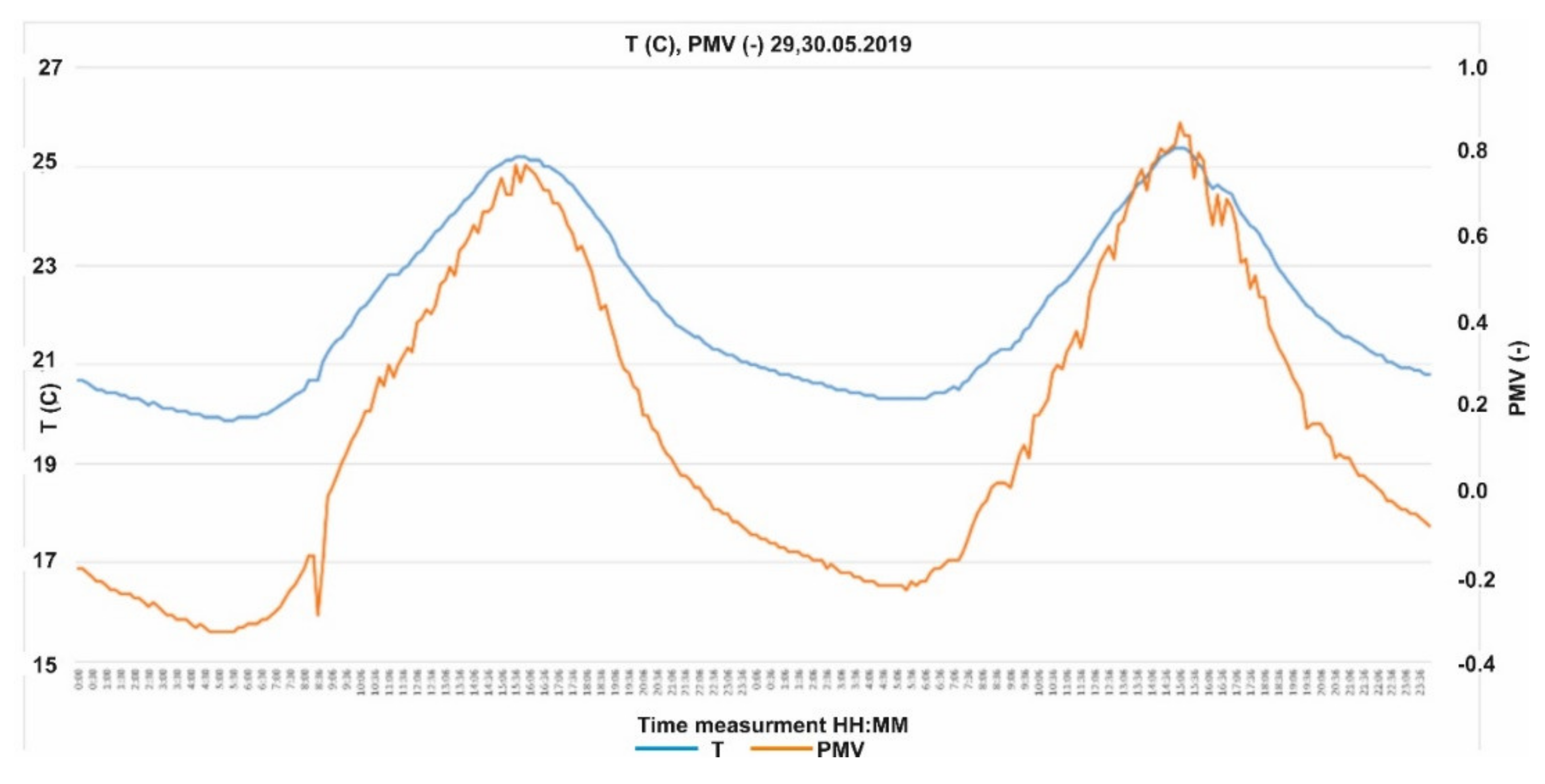
3.4. Microclimate Measurement Results

Microclimate measurements were carried out in the period from 29 May 2019 to 30 May 2019. The maximum temperatures observed during the measurements were about 25 °C and the lowest about 20 °C. The thermal comfort index, expressed in PMV values, ranged from −0.30 to about 0.9. The measuring device was placed in a glass porch and it was possible to clearly observe overheating of this room during the day, which adversely affected the feeling of comfort. This was due to a window with a very high U-value and a relatively high solar radiation transmittance coefficient (at g = 0.75).
During the measurement, windless external conditions prevailed. The entrance door was closed and there were no people in the room. As it was a transition period, no cooling or heating devices were operating. Because there was no forced air movement, the anemometer recorded the multi-minimal air movement speeds. Thus, the local discomfort measurements can be considered irrelevant for this measurement period.
Figure 15 shows a diagram of the indoor temperatures and the PMV calculated from measurements according to Equation (1).

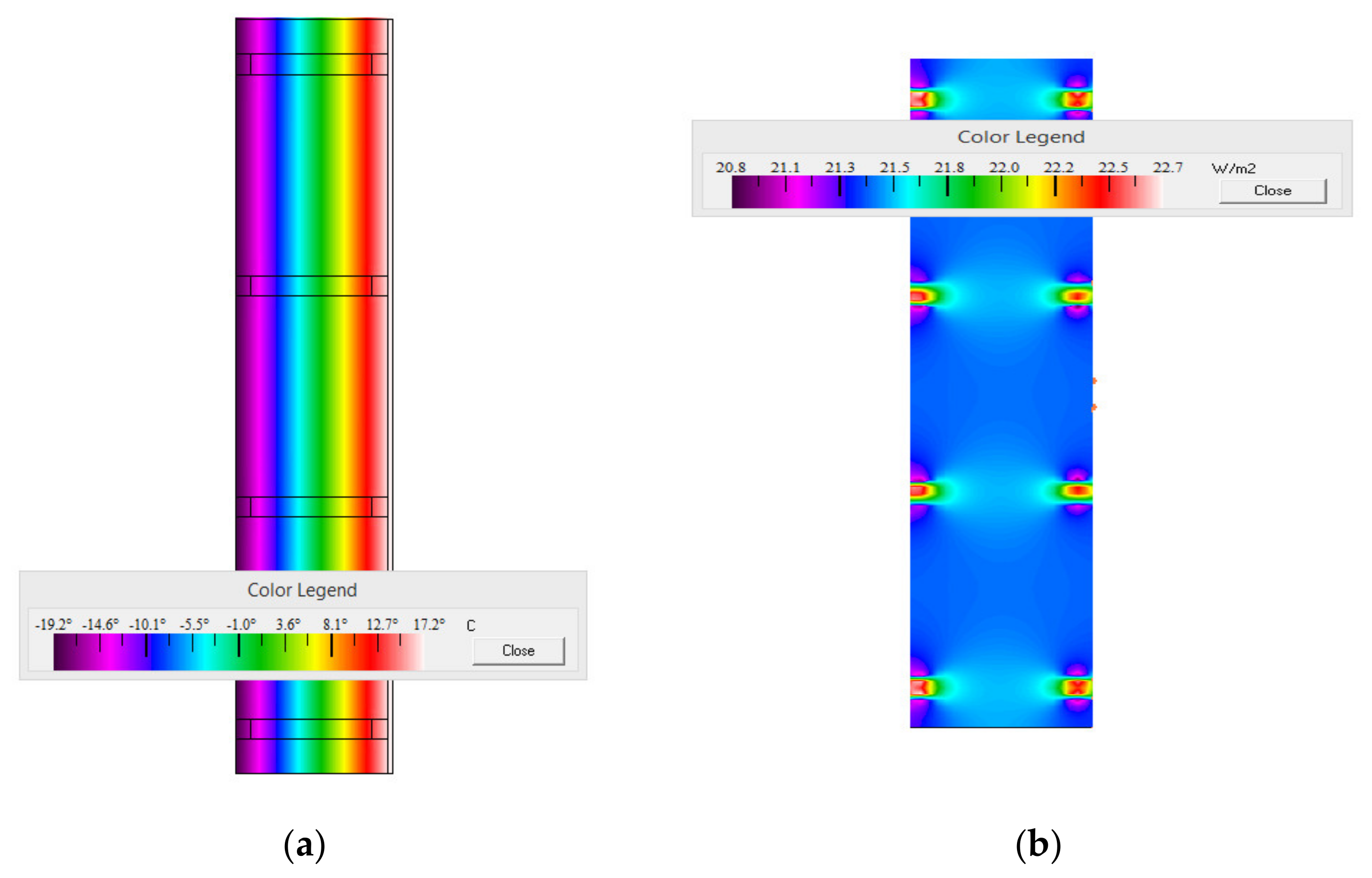
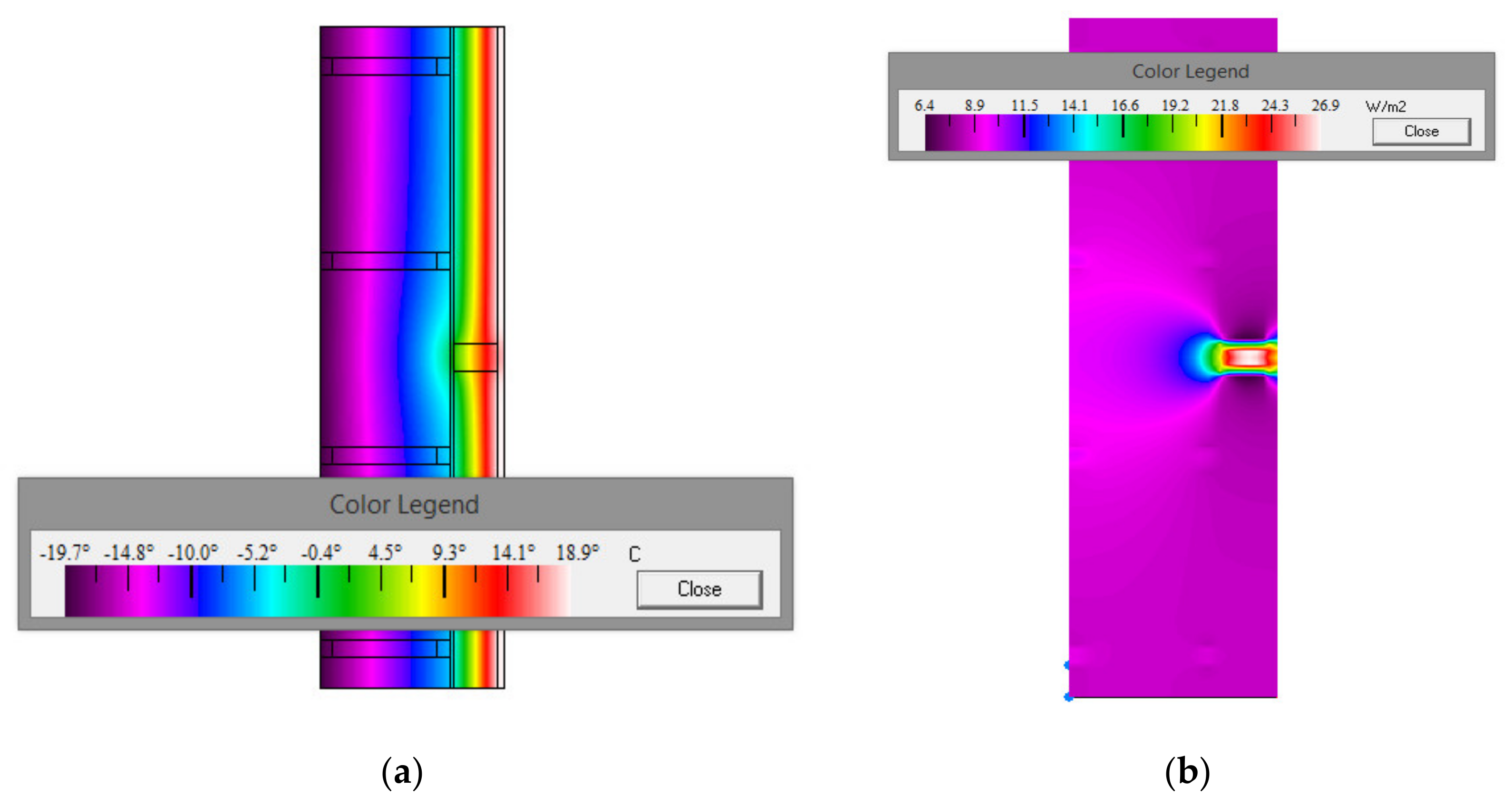
3.5. Results of Numerical Analyses

The assessment of the partitions in question began with a numerical analysis including the calculation of the U thermal transmittance for a non-uniform partition and calculating basic parameters describing a corner-type thermal bridge. The calculations were performed for a partition made from wooden logs with a thickness of 30 cm with a 11 cm thick layer of mineral wool insulation (Figure 16, Figure 17, Figure 18 and Figure 19). The material parameters are listed in Table 5.
The results (Table 6 and Table 7) indicate that there is no risk associated with surface mould development for both the uninsulated and insulated walls. The temperature factor on the internal surface is greater than the limit value for Poland listed in the Ordinance, i.e., 0.72. For both corner detail alternatives, the linear thermal transmittance coefficient had a negative value. The bridges that were detected were not observed to constitute significant thermal anomalies. A comprehensive hygrothermal analysis was performed using WUFI 2D software (WUFI 2D ver. 4.3, Fraunhofer Institut für Bauphysik, Valley, Germany). Based on numerical analyses, time and spatial distributions of water content in the given surfaces of wall systems were calculated. Two partition alternatives were analysed, i.e., a wall insulated from the inside using mineral wool with a thickness of 11 cm (see scheme) and in the second alternative: with light aerated concrete panels with a thickness of 12 cm.
The conclusions regarding the simulation of water increase in the analysed wall layouts are as follows (Figure 20, Figure 21, Figure 22, Figure 23, Figure 24, Figure 25, Figure 26, Figure 27, Figure 28 and Figure 29):
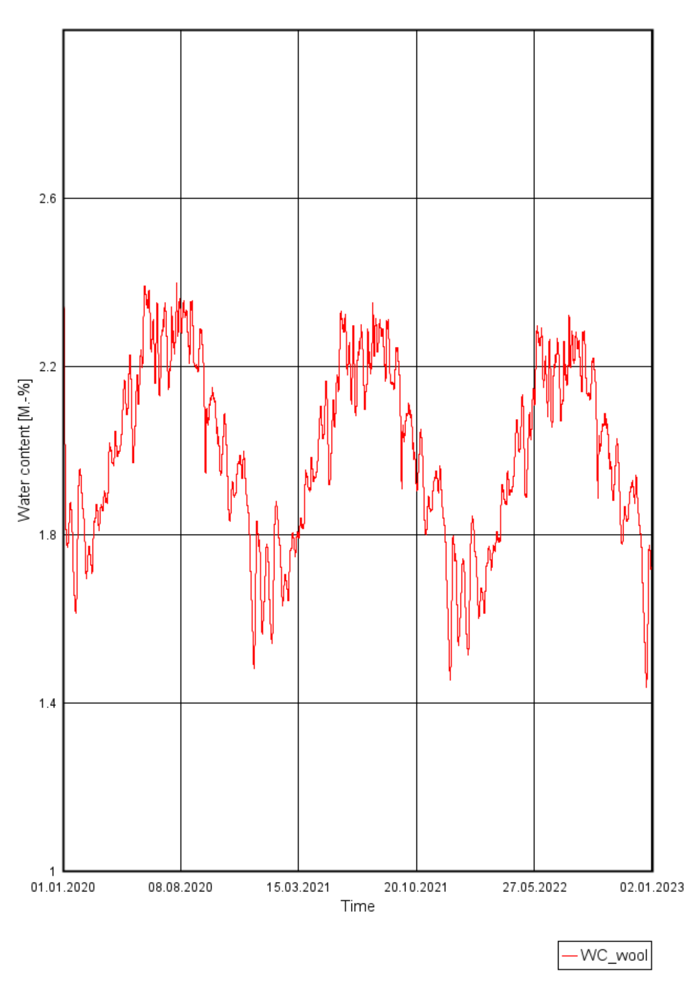
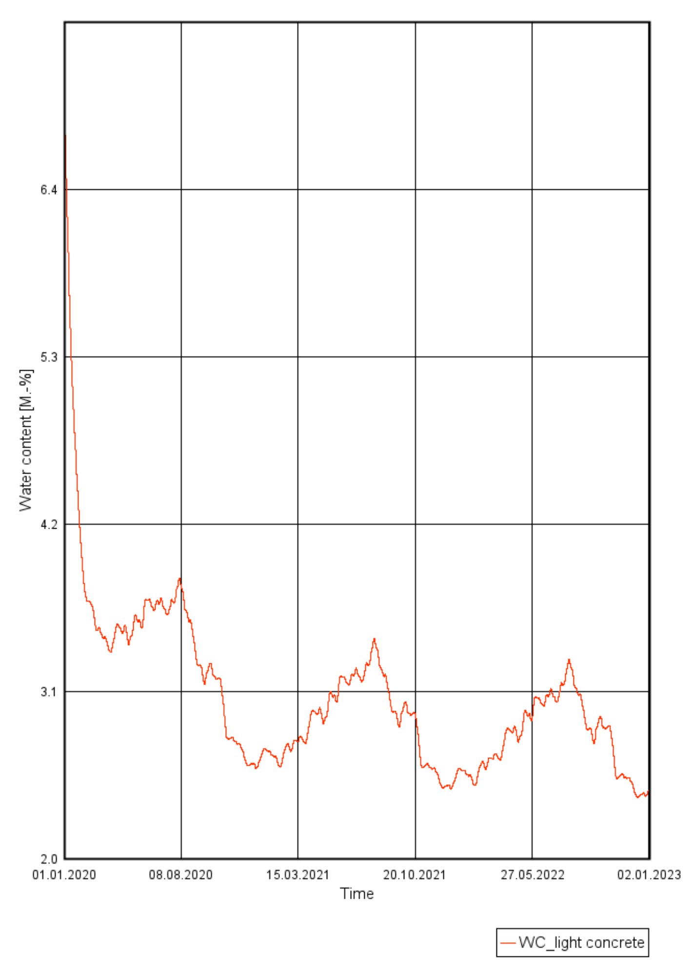
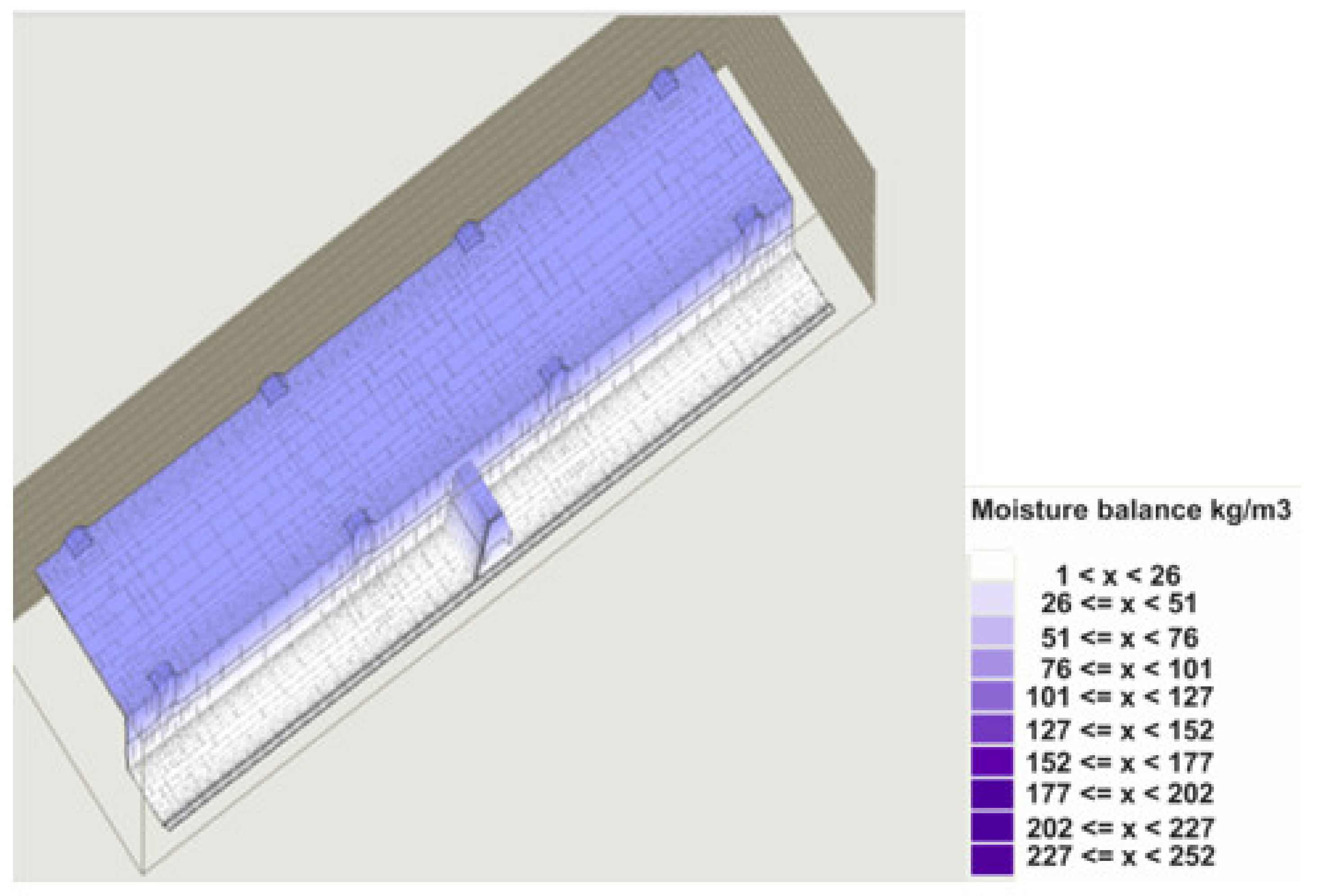
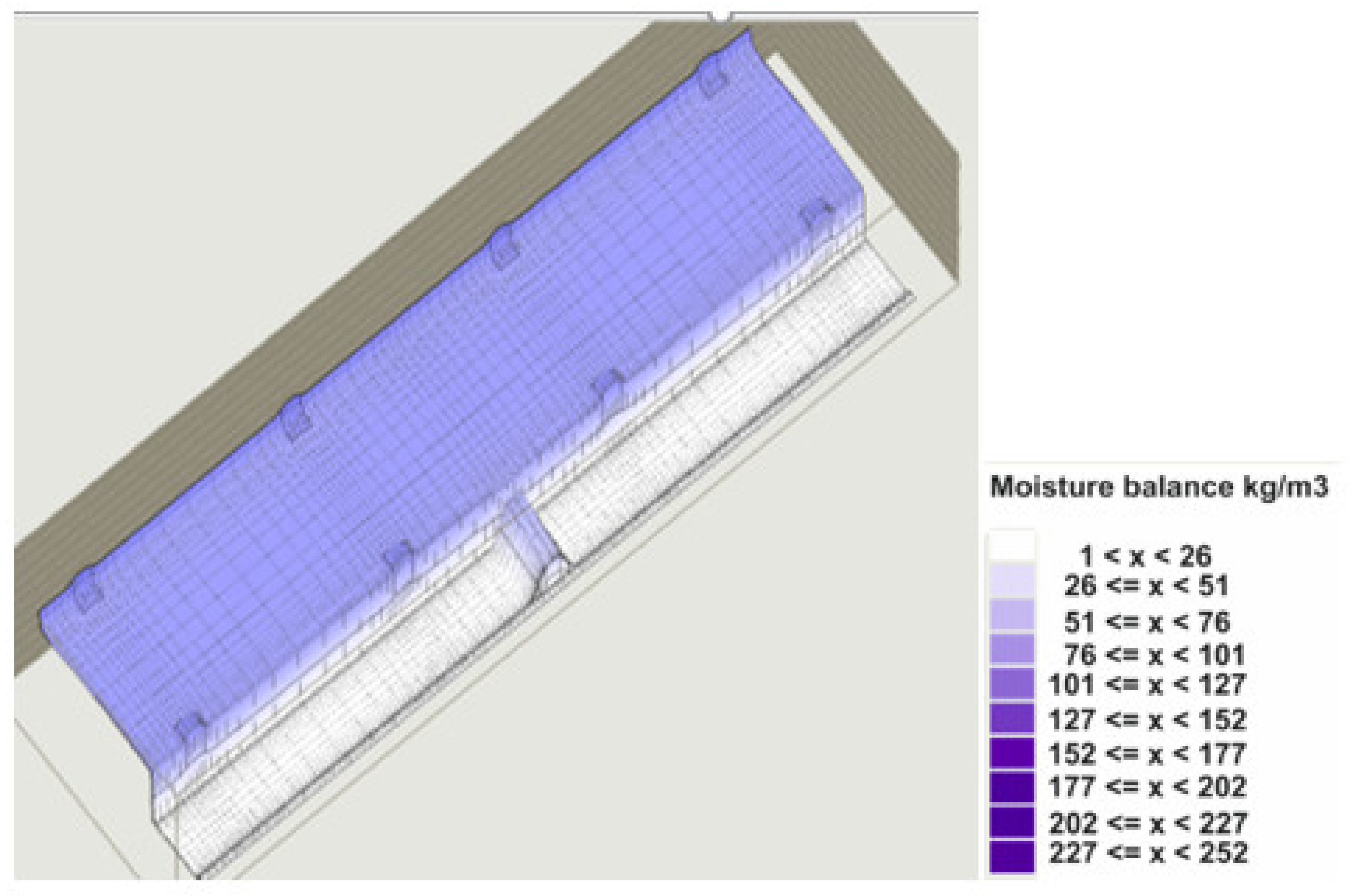
  • No water increase was observed for any type of design solution (mineral wool insulation or light aerated concrete insulation) (Figure 26, Figure 27, Figure 28 and Figure 29). The level of water content decreased by about 66 (kg/m3) after one year of simulations in the local climate for each type of the wall insulation (Figure 20 and Figure 21);
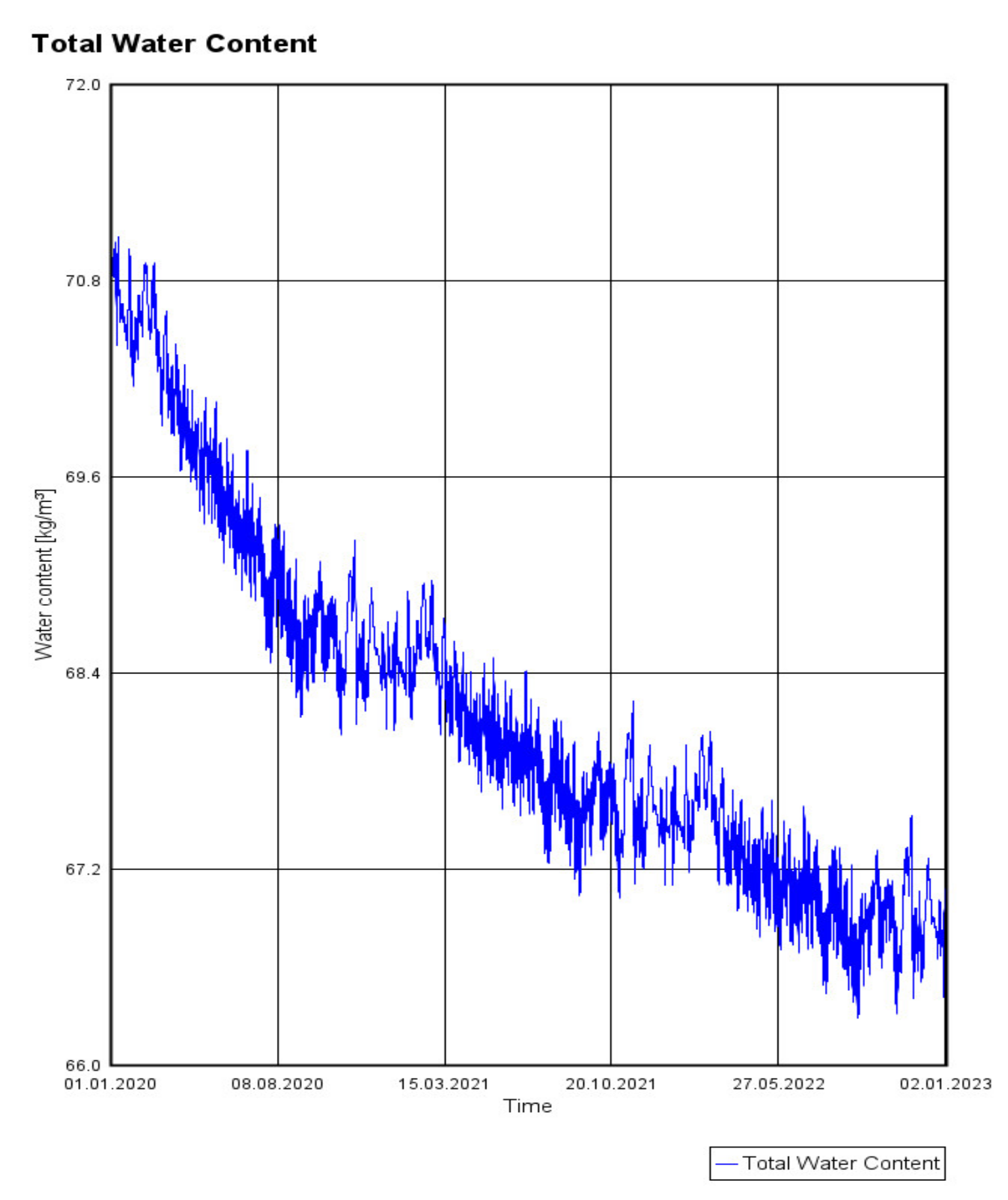
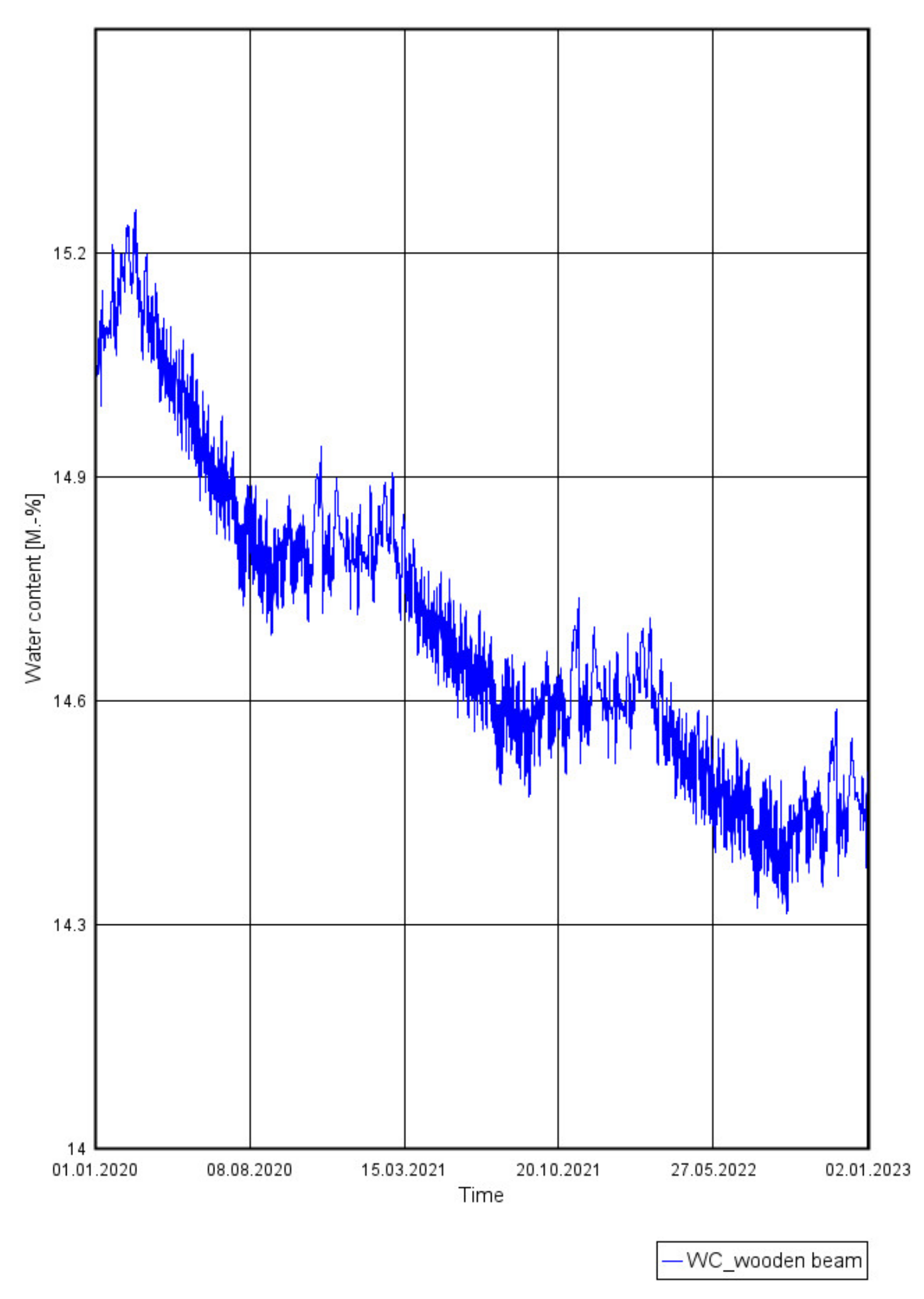
  • A decrease in water content to the level of 14% of the mass humidity was observed for the wooden log walls after one year of simulation. This level is safe in the context of the risk of the development of biological corrosion, which occurs in wooden elements at over 20% of their mass humidity, Figure 22 and Figure 23;
  • In the case of the assessment of the behaviour of the insulation material in a wall layout, no increase in dampness was observed after one year in the assumed conditions of future use. A decrease in water content was observed for both insulation materials, Figure 24 and Figure 25;
Spatial visualisation of water content changes within the partitions.

4. Discussion

Directive 2018/844 on the energy performance of buildings indicates the directions of actions that should be taken nationally to improve the technical conditions of historical buildings and their energy performance, while respecting and preserving national heritage. “Member States should undertake every action to efficiently lower energy consumption and encourage research into, and the testing of, new solutions for improving the energy performance of historical buildings and sites, while also safeguarding and preserving cultural heritage” [15].
Recommendations included in the directive inspired the authors to perform scientific research concerning lowering energy consumption within the highly specific group of the timber buildings of the Podhale region, which is located in the south of Poland. There are practically no guidelines for these buildings concerning renovation with the improvement of their energy performance, comfort of use while respecting cultural heritage. Renovation works in such buildings are usually limited to partial maintenance and small repairs which are usually performed without a dedicated design documentation or by a designer with little experience. The authors have not found any recommendations in national specialist literature on this subject—recommendations that would be based on actual examination of the thermal and moisture conditions of wooden buildings or which would give some guidelines for the design of the insulation of wooden buildings in Podhale. Design solutions are applied in a chaotic manner and their influence on further building use is not analysed at all. The only element of the thermal and moisture analysis which is featured in design documentation, apart from simple U thermal transmittance coefficient calculations, is the examination of condensation between the layers of materials in insulated walls by means of the Glaser method outlined in EN ISO 13 788. In this paper, the authors presented general examples of charts which are the results of such calculations, but they also acknowledged that these charts are not suitable due to the importance of the subject and should not be applied in the case of internal wall insulation, especially wooden external walls of historic buildings. The sensitivity of old wood to changes in its moisture content inclines the authors to state that the introduced changes in wooden wall structure should be performed only by means of simulation methods. Examples of the chaotic insulation of facades of historic wooden buildings, e.g., by means of applying PUR foam on the outside of wall beams can be found on websites dedicated to the subject of insulation. Such activities, which are performed without any prior analyses, do reduce the energy consumption, but they cause the disappearance of the historic wooden facades and contribute to the early degradation of wood. In the authors’ opinion, such insulation practices should be excluded by administrative decision regarding wooden buildings with historic facades and especially in regions with buildings that are highly distinct relative to their landscape, such as Podhale.
The authors presented an innovative approach towards the improvement of thermal quality of historic wooden buildings, accounting for their specific microclimate and preserving cultural heritage. In the authors’ opinion, it is important to perform testing in the right order. The tests should start with documentation analysis, or, if there is no documentation, a building survey should be performed. Afterwards, a general inspection should be performed, leading to further detailed examination. Finally, one should analyse the impact of the proposed insulation on the future use of the building’s spaces. The important element that was presented in this paper is a brief presentation of materials which can be used as internal insulation in historic wooden buildings. The most important materials and technologies (in the authors’ opinion) which should be applied by designers were discussed in the paper.
The actual condition of the historic building under study was determined by a set of in situ tests which included thermovison testing, building envelope airtightness tests and actual U thermal transmittance coefficient tests. The aim of each testing procedure was determined so as to obtain the following: technical and occupancy data necessary for the calculations; simulation of thermal and moisture effects; appropriate design specifications. This approach is innovative and original and accounts for the fact that little to no design documentation of historic buildings survives and identifying actual occupancy conditions, which have a significant impact on potential technical changes, is virtually neglected. In addition, it must be stated that the element of simulation of the future behaviour of wood after the application of the layer of insulation material was included in the building’s technical diagnostics.
The element of discussion, which was, in fact, omitted in this paper, is the thorough examination of wood used in walls, identified as being 115 years old. However, the authors thought that an overview of research on the possible occurrence of mould, fungi or wood-invading pests would be beyond the scope of the paper. Such examinations are usually performed on the order of the local conservator and are not scientific examinations. They belong to standard procedures used in such buildings.
The obtained results of in-situ targeted research enabled the assessment of the condition of thermal protection of wooden walls expressed with the U thermal transmittance coefficient as measured, combined with an airtightness assessment. Additional research enabled the identification of actual indoor space occupancy and comfort of use conditions. The measurement data obtained, i.e., on moisture and temperature, enabled the right choice of these parameters for thermal and moisture simulation. The performed thermal calculations and the simulation of the future behaviour of a partition after applying insulation enabled a clear assessment of the influence of the new design changes on thermal and moisture quality of the partition during its future use. The authors assumed that improving building energy performance while respecting cultural heritage is the correct strategy and provides a suitable example for the domestic implementation of Directive 2018/844.

5. Conclusions

While performing the research, the authors made every effort to obtain results that would be fully representative of the type of building under study. The authors are fully aware that the microclimate measurements they performed were too short in time to provide the appropriate annual set of data for thermal and moisture simulation. The data obtained during the short period of measurement allowed for the avoidance of a significant error, which could have occurred in an ordinary microclimate such as in typical residential buildings. The internal conditions concerning the expected maximum and minimum values of temperature and air moisture, which were required for the thermal and moisture simulation, were created according to the EN 15026 standard. The microclimate in historic wooden buildings should be more thoroughly examined in order to formulate and validate the appropriate database for simulation. The application of such a microclimate, especially regarding historic buildings, would allow for much more accurate prediction of changes of moisture content in partition materials.
The microclimate data collected during the study allowed for formulating initial conclusions concerning the internal comfort improvement potential and achieving the desired external wooden wall parameters. The first steps to improve internal environment comfort are the sealing of the diagnosed cracks in wooden beams and the introduction of elements limiting the overheating of rooms (louvres, sunshades). The next steps of thermal retrofitting involve the insulation of external walls from inside. It is not possible to obtain a heat transfer coefficient of 0.2 W/m2K for all technologies considered in this paper. Technologies which can accomplish this result in a significant reduction in the building’s usable floor area. The conclusions from in situ studies should be used to verify the theoretical model considered in this paper [20] (Table 3). The improvement of thermal insulation of partitions of historic buildings should be considered on a case-by-case basis, depending on the possible thermal retrofitting works. The improvement of thermal insulation of partitions up to the level proposed by the authors in this paper [20] is justified only when thermal retrofitting works of other elements of a historic building are possible, including the replacement of technical installations (heat/cold supply installations, ventilation installations).
Research into this matter will continue. The authors are aware that the constant development in the field of thermal insulation materials will eventually allow the application of better materials and technologies than the ones presented in this paper. However, the authors believe that the presented testing methodology that is to precede project execution should be applied to vernacular timber architecture.
Our future research shall be aimed at:
Research quality improvement, via introducing two new types of testing and assessment of historic buildings: structural system assessment accounting for fungi and moulds, as well as wall mass humidity testing. Mycological testing shall be based on assessing indoor air quality and screening the outer surfaces of partitions for the presence of fungi and moulds. The tests shall be performed using aspiration utilising mycological growth media: Malt Extract Agar (Biomaxima) and Rose Bengal Agar (Biomaxima), utilising a MAS 100 Air Sampler (Merck). Material samples shall be collected from the partitions and seeded onto a base of Sabouraud Glucose Agar (SGA) and Rose Bengal Agar with a yeast extract (RBA). Fungus and mould spore identification shall be performed by studying colony morphology and sporulation structures of the isolated strains using microscopic fungi identification keys. The partition humidity tests shall be performed using a TESTO 635-2 measurement device with a rapid humidity measurement probe. Both tests shall be used to perform in-depth diagnostics of the technical condition of historical building timber partitions. Should high damp levels (>22%) or mould or fungus presence be detected in the partition, a report shall be prepared, outlining the repair procedures to be performed on the historic structure prior to thermal retrofitting. We also want to add to our future tests the indoor air quality (IAQ). Additional analyzes will concern many aspects of the comfort of using historic buildings and indoor air quality (IAQ). Unfortunately, we were unable to include these tests in the diagnostic of the case analysed in the paper (the time for preparing a revised version of the manuscript was very short).
The directions of further research in the area of thermal diagnostics of historic buildings are presented in Figure 30.
The other future directions of research are:
developing procedures that would allow for a fuller diagnostic of the technical condition of historic buildings intended for modernisation (e.g., by using a 3D laser scanner with thermovision capabilities, developed at the Malopolska Energy-Efficient Building Laboratory of the Cracow University of Technology—a device that can combine a building survey with a complete thermal retrofitting documentation).
developing an algorithm for the selection of optimal thermal retrofitting procedures based on architectural design documentation, on-site test results and the findings of analyses proposed by the authors in this paper.

Author Contributions

Conceptualization, M.F.-C., T.S.; Methodology, M.F.-C., E.R.-Z., T.S., B.O.-K.; Software, M.F.-C., B.O.-K., T.S.; Validation, M.F.-C., B.O.-K., E.R.-Z.; Formal Analysis, M.F.-C., T.S.; Investigation, T.T., E.R.-Z., M.F.-C.; Resources, M.F.-C., T.T., E.R.-Z.; Data Curation, M.F.-C., T.T., E.R.-Z.; Writing-Original Draft Preparation, M.F.-C., B.O.-K., T.S.; Writing-Review & Editing, M.F.-C., T.T., E.R.-Z.; Visualization, M.F.-C., B.O.-K., T.S.; Supervision, T.T., E.R.-Z., M.F.-C.; Project Administration, M.F.-C. All authors have read and agreed to the published version of the manuscript.

Funding

This research received no external funding.

Acknowledgments

We would like to thank the management of the Cracow University of Technology for making the Stara Polana building available for study.

Conflicts of Interest

The authors declare no conflict of interest.

References

  1. Dudzik, M.; Jagiello, A.; Drapik, S.; Prusak, J. The selected real tramway substation overload analysis using the optimal structure of an artificial neural network. In Proceedings of the SPEEDAM 2018—Proceedings: International Symposium on Power Electronics, Electrical Drives, Automation and Motion, Amalfi, Italy, 20–22 June 2018; pp. 413–417. Available online: https://ieeexplore.ieee.org/document/8445340 (accessed on 2 September 2020).
  2. Radziszewska-Zielina, E.; Rumin, R. Analysis Of The Profitability of Investment In Renewable Energy Sources On The Example of A Semi-Detached House. E3S Web Conf. 2016, 10, 79. [Google Scholar] [CrossRef] [Green Version]
  3. Romanska-Zapala, A.; Bomberg, M.; Dechnik, M.; Fedorczak-Cisak, M.; Furtak, M. On Preheating of the Outdoor Ventilation Air. Energies 2019, 13, 15. [Google Scholar] [CrossRef] [Green Version]
  4. European Parliament. Directive 2002/91/EC of the European Parliament And of the Council of 16 December 2002 on the Energy Performance of Buildings; European Parliament: Brussels, Belgium, 2002. [Google Scholar]
  5. European Parliament. Directive 2010/31/EU of the European Parliament and of the Council of 19 May 2010 on the Energy Performance of Buildings; European Parliament: Brussels, Belgium, 2010. [Google Scholar]
  6. Minister of Infrastructure. Holling of the Minister of Infrastructure and Development of 17 July 2015 on the Announcement of the Consolidated Text of the Regulation of the Minister of Infrastructure on the technical conditions to be Met by Buildings and Their Location; Minister of Infrastructure: Warsaw, Poland, 2015. [Google Scholar]
  7. Chancellery of the Sejm of the Republic of Poland. Law of 7 July 1994 Building Law; Chancellery of the Sejm of the Republic of Poland: Warsaw, Poland, 2010. [Google Scholar]
  8. Radziszewska-Zielina, E.; Śladowski, G. Proposal of the Use of a Fuzzy Stochastic Network for the Preliminary Evaluation of the Feasibility of the Process of the Adaptation of a Historical Building to a Particular Form of Use. IOP Conf. Ser. Mater. Sci. Eng. 2017, 245, 072029. [Google Scholar] [CrossRef]
  9. Radziszewska-Zielina, E.; Śladowski, G. Supporting the selection of a variant of the adaptation of a historical building with the use of fuzzy modelling and structural analysis. J. Cult. Herit. 2017, 26, 53–63. [Google Scholar] [CrossRef]
  10. Radziszewska-Zielina, E.; Śladowski, G.; Sibielak, M. Planning the reconstruction of a historical building by using a fuzzy stochastic network. Autom. Constr. 2017, 84, 242–257. [Google Scholar] [CrossRef]
  11. Krentowski, J.; Chyzy, T.; Dunaj, P. Sudden collapse of a 19th-century masonry structure during its renovation process. Eng. Fail. Anal. 2017, 82, 540–553. [Google Scholar] [CrossRef]
  12. Krentowski, J.R.B.; Mlonek, S.; Zimiński, K.T.A. Structural and Technological Aspects of the Historical Floors Replacement. Available online: https://www.researchgate.net/publication/331314077_Structural_and_Technological_Aspects_of_the_Historical_Floors_Replacement (accessed on 9 May 2020).
  13. Yarbrough, D.W.; Bomberg, M.; Romanska-Zapala, A. Buildings with environmental quality management, part 3: From log houses to environmental quality management zero-energy buildings. J. Build. Phys. 2019, 42, 672–691. [Google Scholar] [CrossRef]
  14. Romanska-Zapala, A.; Bomberg, M.; Yarbrough, D.W. Buildings with environmental quality management: Part 4: A path to the future NZEB. J. Build. Phys. 2019, 43, 3–21. [Google Scholar] [CrossRef]
  15. European Parliament. Directive (EU) 2018/844 of the European Parliament And of the Council of 30 May 2018 amending Directive 2010/31/EU on the Energy Performance of Buildings and Directive 2012/27/EU on Energy Efficiency (Text with EEA relevance); European Parliament: Brussels, Belgium, 2018. [Google Scholar]
  16. Piasecki, M. Practical Implementation of the Indoor Environmental Quality Model for the Assessment of Nearly Zero Energy Single-Family Building. Buildings 2019, 9, 214. [Google Scholar] [CrossRef] [Green Version]
  17. Piasecki, M. Kostyrko Combined Model for IAQ Assessment: Part 1—Morphology of the Model and Selection of Substantial Air Quality Impact Sub-Models. Appl. Sci. 2019, 9, 3918. [Google Scholar] [CrossRef] [Green Version]
  18. Rejestr Zabytków Nieruchomych—Otwarte Dane. Available online: https://dane.gov.pl/dataset/1130 (accessed on 23 April 2020).
  19. Nowogońska, B. The Method of Predicting the Extent of Changes in the Performance Characteristics of Residential Buildings. Arch. Civ. Eng. 2019, 65, 81–89. [Google Scholar] [CrossRef]
  20. Fedorczak-Cisak, M.; Kowalska, A.; Radziszewska-Zielina, E.; Śladowski, G.; Pachla, F.; Tatara, T. A multi-criteria approach for selecting the utility function of the historical building “Stara Polana” located in Zakopane. MATEC Web Conf. 2019, 262, 07002. [Google Scholar] [CrossRef]
  21. Fedorczak-Cisak, M.; Kotowicz, A.; Radziszewska-Zielina, E.; Sroka, B.; Tatara, T.; Barnaś, K. Multi-Criteria Optimisation of an Experimental Complex of Single-Family Nearly Zero-Energy Buildings. Energies 2020, 13, 1541. [Google Scholar] [CrossRef] [Green Version]
  22. Fedorczak-Cisak, M.; Kowalska-Koczwara, A.; Nering, K.; Pachla, F.; Radziszewska-Zielina, E.; Śladowski, G.; Tatara, T.; Ziarko, B. Evaluation of the criteria for selecting proposed variants of utility functions in the adaptation of historic regional architecture. Sustainability 2019, 11, 1094. [Google Scholar] [CrossRef] [Green Version]
  23. Dudzik, M.; Mielnik, R.; Wrobel, Z. Preliminary analysis of the effectiveness of the use of artificial neural networks for modeling time-voltage signal of the combination wave generator. In Proceedings of the 18th International Symposium on Electromagnetic Fields in Mechatronics, Electrical and Electronic Engineering, ISEF 2017, Lodz, Poland, 14–16 September 2017; Institute of Electrical and Electronics Engineers Inc.: Lodz, Poland, 2017. [Google Scholar]
  24. Józef, T. Styl alpejski w środkowej Europie i polska kontrakcja wobec niego—Styl zakopiański—Estetyka i Krytyka—Issue 2(25) (2012)-CEJSH-Yadda. Estetyka Krytyka 2012, 2, 232–246. [Google Scholar]
  25. “Dawne Zakopane” Nasza Politechnika. Available online: http://riad.pk.edu.pl/~naszapol/np53/str36b.shtml (accessed on 25 April 2020).
  26. International Organization for Standardization. ISO 13788:2012 Hygrothermal Performance of Building Components and Building Elements—Internal Surface Temperature to Avoid Critical Surface Humidity and Interstitial Condensation—Calculation methods; International Organization for Standardization: Geneva, Switzerland, 2012. [Google Scholar]
  27. Deutsches Institut für Normung. DIN 4108-3 Grenzen der Anwendbarkeit im Feuchteschutz|Bauphysik|Feuchteschutz|Baunetz_Wissen; Deutsches Institut für Normung: Berlin, Germany, 1996. [Google Scholar]
  28. Orlik-Kożdoń, B. Interior insulation of masonry walls-selected problems in the design. Energies 2019, 12, 3895. [Google Scholar] [CrossRef] [Green Version]
  29. Orlik-Kożdoń, B.; Steidl, T. Impact of internal insulation on the hygrothermal performance of brick wall. J. Build. Phys. 2017, 41, 120–134. [Google Scholar] [CrossRef]
  30. Orlik-Kożdoń, B.; Szymanowska-Gwiżdż, A. Impact of envelope structure on the solutions of thermal insulation from the inside. Archit. Civ. Eng. Environ. 2018, 11, 123–134. [Google Scholar] [CrossRef] [Green Version]
  31. Kozakiewicz, P.; Matejak, M. Wydawnictwo Szkoły Głównej Gospodarstwa Wiejskiego. In Klimat a Drewno Zabytkowe: Dawna i Współczesna Wiedza o Drewnie; Wydawnictwo Warsaw University of Life Sciences: Warsaw, Poland, 2013; ISBN 9788375835076. [Google Scholar]
  32. Künzel, H. Criteria defining rain protecting external rendering systems. In Energy Procedia; Elsevier Ltd.: Amsterdam, The Netherlands, 2015; Volume 78, pp. 2524–2529. [Google Scholar]
  33. WTA. Eßmann Innendämmung Nach WTA I Planungsleitfaden Merkblatt 6-4 Inside insulation Acco–Rding to WTA I: Planary Guide Isolation Thermique par l´Intérieur Selon WTA I: Guide de Planification Deskriptoren; Fraunhofer IRB Verlag: Stuttgart, Germany, 2016; ISBN 9783816780861. [Google Scholar]
  34. Biolek, V.; Hanák, T. LCC Estimation Model: A Construction Material Perspective. Buildings 2019, 9, 182. [Google Scholar] [CrossRef] [Green Version]
  35. Multipor Ocieplenie od Wewnątrz Zeszyt Techniczny. Available online: https://www.ytong-silka.pl/pl/docs/Zeszyt-techniczny-Multipor-Ocieplenie-od-wewnatrz-2017-03.pdf (accessed on 24 April 2020).
  36. Epatherm, Renowacje, Ocieplenia od Wewnatrz. Available online: http://www.epasit.pl/php/start.php (accessed on 24 April 2020).
  37. Radziszewska-Zielina, E.; Czerski, P.; Grześkowiak, W.K.-S.P. Comfort of Use Assessment in Buildings with Interior Wall Insulation based on Silicate and Lime System in the Context of the Elimination of Mould Growth. Arch. Civ. Eng. 2020, 2, 89–104. [Google Scholar]
  38. Karta Badań Skuteczności AERO-THERM®. Available online: http://www.aerotherm.eu/wp-content/uploads/2015/08/Karta-bada%C5%84-skuteczno%C5%9Bci-dzia%C5%82ania-AT-2014.pdf (accessed on 2 September 2020).
  39. Kożuch, B.; Tatara, T. Impact of the vibrations on the environment caused by passages of trains at variable speed. E3S Web Conf. 2016, 10, 00047. [Google Scholar] [CrossRef] [Green Version]
  40. Polish Standardization Committee. PN-EN ISO—ISO 6946:2017—Building Components and Building Elements—Thermal Resistance and Thermal Transmittance—Calculation Methods; Polish Standardization Committee: Warsaw, Poland, 2017. [Google Scholar]
  41. Polish Standardization Committee. PN-EN 12524:2003 Building Materials and Products—Thermal and Humidity Characteristics—Tabulated Design Values; Polish Standardization Committee: Warsaw, Poland, 2003. [Google Scholar]
  42. Radziszewska-Zielina, E.; Kania, E.; Śladowski, G.X. Problems of the selection of construction technology for structures in the centres of urban agglomerations. Arch. Civ. Eng. 2018, 64, 55–71. [Google Scholar] [CrossRef]
  43. Radziszewska-Zielina, E.; Kania, E. Problems in Carrying Out Construction Projects in Large Urban Agglomerations on the Example of the Construction of the Axis and High5ive Office Buildings in Krakow. MATEC Web Conf. 2017, 117, 00144. [Google Scholar] [CrossRef]
  44. Polish Standardization Committee. PN-EN 13187 “Thermal Performance of Buildings—Qualitative Detection of Thermal Defects in Building Envelope—Infrared Method”; Polish Standardization Committee: Warsaw, Poland, 2001. [Google Scholar]
  45. Henryk, N. Zastosowanie Badań Termowizyjnych w Budownictwie. Oficyna Wydawnictwo Politechniki Wrocławskiej; Wydawnictwo Politechniki Wrocławskiej: Wrocław, Poland, 2012. [Google Scholar]
  46. Steidl, T.; Belok, T.; Krause, P.; Nowoświat, A.; Orlik-Kożdoń, B.; Wojewódka, D. Poradnik Diagnostyki Cieplnej Budynków: Praca Zbiorowa Diagnostyka In Situ Izolacyjności Cieplnej Budynków, Tom 1; Politechnika Śląska, Wydział Inżynierii Środowiska i Energetyki: Gliwice, Poland, 2013. [Google Scholar]
  47. Polish Standardization Committee. PN ISO 6781:1983. Thermal Insulation–Qualitative Detection of Thermal Irregularieties Inbuilding Envelopes—Infrared Method; Polish Standardization Committee: Warsaw, Poland, 1983. [Google Scholar]
  48. D’Ambrosio Alfano, F.; Dell’Isola, M.; Ficco, G.; Palella, B.; Riccio, G. Experimental Air-Tightness Analysis in Mediterranean Buildings after Windows Retrofit. Sustainability 2016, 8, 991. [Google Scholar] [CrossRef] [Green Version]
  49. Polish Standardization Committee. PN-EN ISO 9972: 2015-10. Thermal Properties of Buildings—Determination of Air Permeability Of Buildings—Pressure Measurement Method with the Use of a Fan; Polish Standardization Committee: Warsaw, Poland, 2015. [Google Scholar]
  50. Polish Standardization Committee. PN ISO 9869-1:2014—Thermal Insulation—Building Elements—In-Situ Measurement of Thermal Resistance and Thermal Transmittance—Part 1: Heat Flow Meter Method; Polish Standardization Committee: Warsaw, Poland, 2014. [Google Scholar]
  51. Polish Standardization Committee. PN-EN 16798-1:2019-06 Energy Performance of Buildings—Ventilation for Buildings—Part 1: Indoor Environmental Input Parameters for Design and Assessment of Energy Performance of Buildings Addressing Indoor Air Quality, Thermal Environment, Lighting a; Polish Standardization Committee: Warsaw, Poland, 2019. [Google Scholar]
  52. Polish Standardization Committee. PN EN 15251: 2007. Indoor Environmental Input Parameters for Design and Assessment of Energy Performance of Buildings Addressing Indoor Air Quality, Thermal Environment, Lighting and Acoustics; Polish Standardization Committee: Warsaw, Poland, 2007. [Google Scholar]
  53. Fanger, P.O. Thermal Comfort: Analysis and Applications in Environmental Engineering; Danish Technical Press: Copenhagen, Denmark, 1970; ISBN1 8757103410. ISBN2 9788757103410. [Google Scholar]
  54. D’Ambrosio Alfano, F.R.; Palella, B.I.; Riccio, G.; Toftum, J. Fifty years of Fanger’s equation: Is there anything to discover yet? Int. J. Ind. Ergon. 2018, 66, 157–160. [Google Scholar] [CrossRef]
  55. Polish Standardization Committee. PN-EN ISO 7730: 2006. Ergonomics of The Thermal Environment—Analytical Determination and Interpretation of Thermal Comfort Using the Calculation of PMV and PPD Indicators and Criteria of Local Thermal Comfort; Polish Standardization Committee: Warsaw, Poland, 2005. [Google Scholar]
  56. Polish Standardization Committee. PN ISO 7726: 2001. Ergonomics of the Thermal Environment. Instruments for Measuring Physical Quantities; Polish Standardization Committee: Warsaw, Poland, 2001. [Google Scholar]
  57. WTA. Innendämmung Nach WTA I Planungsleitfaden, Referat 6 Bauphysik und Bauchemie; Wissenschaftlich-Technische Arbeitsgemeinschaft für Bauwerkserhaltung und Denkmalpflege, Ed.; Fraunhofer IRB Verlag: Stuttgart, Germany, 2009. [Google Scholar]
  58. Polish Standardization Committee. PN EN ISO 10211:2017 Thermal Bridges in Building Construction—Heat Flows and Surface Temperatures—Detailed Calculations; Polish Standardization Committee: Warsaw, Poland, 2017. [Google Scholar]
  59. European Committee for Standardization. EN 15026; Hygrothermal Performance of Building Components and Building Elements—Assessment of Moisture Transfer by Numerical Simulation; European Committee for Standardization: Brussels, Belgium, 2012. [Google Scholar]
  60. Nowoświat, A.; Skrzypczyk, J.; Krause, P.; Steidl, T.; Winkler-Skalna, A. Estimation of thermal transmittance based on temperature measurements with the application of perturbation numbers. Heat Mass Transf. 2018, 54, 1477–1489. [Google Scholar] [CrossRef] [Green Version]
Figure 1. Temperature and vapour pressure charts, calculated as per PN-EN ISO 13788: 2013-05 [26] for applying thermal insulation to an external wall (no condensation) from inside (a) and outside (b) (problems with inter-layer condensation). Psi—saturated vapour pressure, P—actual vapour pressure, Ti—indoor temperature, Te—outdoor temperature.
Energies 13 04610 g001
Figure 2. Minimal requirements for the thermal insulation layer depending on the thermal resistance of the insulation for bases displaying different capillary activity [33].
Energies 13 04610 g002
Figure 3. General principle of the functioning of partitions insulated from the inside using aerated concrete panels. (a) Late autumn period, (b) transition from winter to spring, condensation of water vapour inside the partition, (c) spring/summer, the partition becomes dry [35].
Energies 13 04610 g003
Figure 4. Cross section of a wall with traditional internal thermal insulation and actual vapour pressure charts P and saturated vapour pressure Ps.
Energies 13 04610 g004
Figure 5. Standard procedure for thermal diagnostics of historic buildings and a new procedure proposed by the authors.
Energies 13 04610 g005
Figure 6. (a) Front facade. (b) General thermovision analysis of the Stara Polana building using a FLIR camera.
Energies 13 04610 g006
Figure 7. Envelope airtightness test performed on the Stara Polana building. Location of the Blower Door device in the entrance door. Reproduced from [22].
Energies 13 04610 g007
Figure 8. Measurement of the thermal transmittance coefficient in wooden log walls (a) with locations of measurement equipment marked on a part of the building plan (b).
Energies 13 04610 g008
Figure 9. Microclimate measurement station in the Stara Polana building in a south-facing, glazed hall. Reproduced from [22].
Energies 13 04610 g009
Figure 10. Detailed thermovision analysis of the Stara Polana building using a FLIR camera. Fragment of an external wooden log wall.
Energies 13 04610 g010
Figure 11. Analysis of a selected temperature distribution field for a wooden log wall.
Energies 13 04610 g011
Figure 12. Precision thermogram along with points and temperature measurement fields and an additional temperature distribution field chart (B × 1 and B × 2).
Energies 13 04610 g012
Figure 13. Sample precision thermogram. Analysis of temperature field distribution in the selected fragment.
Energies 13 04610 g013
Figure 14. Results of testing intended to determine the actual U thermal transmittance for a wall made from wooden logs, located on the ground floor of the Stara Polana building. Temperature and heat stream density measurements.
Energies 13 04610 g014
Figure 15. Indoor temperatures and Predicted Mean Vote (PMV) coefficient.
Energies 13 04610 g015
Figure 16. Comparison of calculation results for a wall made from horizontal logs without thermal insulation (a—isotherm layout, b—heat stream density distribution).
Energies 13 04610 g016
Figure 17. Comparison of calculation results for a wall made from horizontal logs with a thermal insulation layer 11 cm thick (a—isotherm layout, b—heat stream density distribution).
Energies 13 04610 g017
Figure 18. Comparison of calculation results for a wall corner without thermal insulation (a—isotherm layout, b—heat stream density distribution).
Energies 13 04610 g018
Figure 19. Comparison of calculation results for a wall corner with a thermal insulation layer 11 cm thick (a—isotherm layout, b—heat stream density distribution).
Energies 13 04610 g019
Figure 20. Changes in water content—partition insulated with mineral wool.
Energies 13 04610 g020
Figure 21. Changes in water content—partition insulated using light aerated concrete.
Energies 13 04610 g021
Figure 22. Changes in water content in a wooden beam—partition insulated with mineral wool.
Energies 13 04610 g022
Figure 23. Changes in water content in a wooden beam—partition insulated using light aerated concrete.
Energies 13 04610 g023
Figure 24. Changes in water content in the insulation material layer—mineral wool.
Energies 13 04610 g024
Figure 25. Changes in water content in the insulation material layer—light aerated concrete.
Energies 13 04610 g025
Figure 26. Wall insulated using mineral wool—initiation time (0 h).
Energies 13 04610 g026
Figure 27. Wall insulated with light aerated concrete—initiation time (0 h).
Energies 13 04610 g027
Figure 28. Wall insulated with mineral wool—completion time (3 years).
Energies 13 04610 g028
Figure 29. Wall insulated with light aerated concrete—completion time (3 years).
Energies 13 04610 g029
Figure 30. The directions for further research.
Energies 13 04610 g030
Table 1. Thermal transmittance of the external walls of the Stara Polana building, as assumed for calculations.
No.Building ElementScheme (-)U Coefficient Assumed for Calculations W/(m2K)
1Basement wall Energies 13 04610 i0011.73; 2.20; 2.35
Parameters assumed as for a crushed stone wall with a 35% mortar content by volume, with a stone density of kg/m3
2 Ground floor wall Energies 13 04610 i0022.59; 0.50
(as above); wood (pine/spruce, across the fibres)
Table 2. Required thermal insulation layer thicknesses for the materials under analysis (m).
Type of WallExtant U W/m2KW1 *W2 *W3 *W4 *W5 *
λ = 0.04λ = 0.022λ = 0.042λ = 0.047λ = 0.067
Thickness of each thermal insulation material necessary for attaining U = 0.2 W/(m2K) for the entire partition
Basement wall—stone d = 1.02 m 1.73 0.17 0.10 0.19 0.21 0.30
Basement wall—stone d = 0.71 m 2.20 0.17 0.10 0.19 0.21 0.30
Basement wall—stone d = 0.64 m 2.35 0.18 0.10 0.19 0.21 0.31
Ground floor wall—stone d = 0.54 m 2.59 0.18 0.10 0.19 0.22 0.31
Ground floor wall—wood d = 0.30 m 0.49 0.11 0.07 0.12 0.14 0.20
* W1—mineral wool, W2—PIR/PUR foam, W3—light aerated concrete, W4—silicate coating, W5—calcium silicate climate panels.
Table 3. Classes of thermally retrofitted historic buildings depending on the thermal transmittance U for external walls [20].
Class of Building Depending on Attained Value of U W/(m2K)U W/(m2K)
class A0.00–0.15
class B0.16–0.22
class CU ≥ 0.23
Table 4. Data from measurement sensors.
Type of SensorMeasurement RangeScaleAccuracy
Temperature sensors−20 °C + 50 °C (wet thermometer 0 °C + 50 °C)0.01 °C±0.4 °C
Humidity sensors0–100%0.1 RH (relative humidity)±2% RH (relative humidity)
Air velocity sensors0–5 m/s0.01 m/sfor 0–1 m/s ± 0.05 + 0.05 Va m/s, for 1–5 m/s ± 5%
Table 5. Listing of data assumed for analysis.
Materialλ W/mKµCρTechnological Water Content (Initial) kg/m3
-J/kg Kkg/m3
Wooden beams0.16200140065098.0
Mineral wool0.0381840320.8
Light aerated concrete0.0448501158.1
Gypsum plasterboard0.32200140040015.5
Vapour barrier2.3027,0002300130-
Table 6. Comparison of results (for the alternative featuring thermal insulation with mineral wool λ = 0.038 W/(mK)).
Thermal Transmittance UUninsulated WallInsulated Wall (11 cm)
Calculations0.490.20
W/(m2K)Measurements0.60–0.65-
Table 7. Comparison of calculation results.
Indicator ValuesUninsulated WallInsulated Wall (11 cm)
fRsi (-)0.8350.88
L2D W/mK0.7610.326
Ψi W/mK−0.37−0.14

