Article

Photo-Rechargeable Electric Energy Storage Systems Based on Silicon Solar Cells and Supercapacitor-Engineering Concept

by
Ireneusz Plebankiewicz
,
Krzysztof Artur Bogdanowicz
* and
Agnieszka Iwan
*
Military Institute of Engineer Technology, Obornicka 136 Str., 50-961 Wroclaw, Poland
*
Authors to whom correspondence should be addressed.
Energies 2020, 13(15), 3867; https://doi.org/10.3390/en13153867
Submission received: 25 June 2020 / Revised: 18 July 2020 / Accepted: 24 July 2020 / Published: 28 July 2020
(This article belongs to the Special Issue Assessment of Photovoltaic-Battery Systems)

Abstract

:
Recently, use of supercapacitors as energy storage systems has attracted considerable attention. However, the literature is scarce of information about the optimization of hybrid systems, using supercapacitors as the main energy storage system. In our study, we focused step-by-step on the engineering concept of a photo-rechargeable energy storage system based on silicon solar cells and supercapacitors. In the first step, based on commercially available elements, we designed a solar charger and simulated its work in idealized conditions. Secondly, we designed appropriate electronic connections and control systems, allowing for the charging–discharging process of the energy storage system. After constructing three type of demonstrators of solar energy charger, we tested it. The novel design allowed us to achieve total available energy from solar panel energy conversion up to 93%.

Graphical Abstract

1. Introduction

Efficient energy generation using sun-to-energy converting systems depends highly on the weather conditions, making it difficult to rely on them alone. Additionally, energy production is only possible during the sunny hours throughout the day, limiting greatly its direct consumption to a few hours per day [1]. The energy demand is higher during night hours; therefore, a mismatch typically exists between daily demand and supply. In order to face these requirements, the development of energy storage units (ESU) becomes a must in such circumstances [2]. The most important characteristic of an ESU is the energy and the power available under a certain load. Among currently available technologies, the energy storage units can be based on batteries, capacitors, supercapacitors (SC), flywheels, and magnetic ESUs. In order to compare the performance of different energy storage units, the energy density and power density can be plotted, giving the so-called Ragone plot [3]. The major differences between all energy storage units are:
  • Criteria when the energy is stored,
  • Charging/discharging conditions,
  • Depth of discharge,
  • Lifetime,
  • Storage period/self-discharge [2].
The mostly commonly used energy storage devices are batteries (electrochemical cells) due to their low self-discharge and possibility to store the energy immediately for later use. However, rapid changes in illumination conditions also causes fluctuation of the generated power from the photovoltaic (PV) system [4]. Hybrid systems composed of the supercapacitors and batteries are known in the literature. This kind of connection allows for a combination of advantages of both systems: supercapacitors smooth the variation of the generated energy from PV and compensate the decay of to the battery during energy production [4,5,6].
Interestingly, from the Ragone plot (in logarithmic scale), it can be noticed that supercapacitors are placed somewhere in between batteries and conventional capacitors, providing a reasonable midpoint between the two [6]. Other advantages of supercapacitors are durability up to 10 years, high efficiency (approx. 95%), resistant to deep discharge/overcharge and high power density of 10,000 W/kg. Other benefits of using supercapacitors directly connected to variable renewable electricity sources (VRES) generators include removing the need for DC/AC converters. [7]. Even though supercapacitors seem promising as standalone energy storage systems, there have been only a few reports in the literature regarding the subject in recent few years.
Logerais and coworkers [8] focused on presenting both experimental and modeling approaches for supercapacitors as storage for photovoltaic energy. The experimental studies were performed in real conditions for a photovoltaic array connected to a supercapacitor storage system. Moreover, the comparison of real data with mathematical models were in good agreement, with ±10% for the supercapacitor charge/discharge cycles. The variability was assigned to temperature-dependent performance. They have also proved the use of supercapacitors as storage systems.
Kularatna et al. [9] studied via mathematical modeling a design approach for minimizing potential losses caused by separating the load and the storage device. The authors [9] proposed a new charging approach to create two separate loops for charging and discharging. It means that, at the moment of charging, one of the supercapacitor (SC) banks is connected to the first loop, while the other one is in discharge mode trying to reach the same energy load. Additionally, when connected to two PV of 12 V each, it is possible to charge the SC from 10 V to 13.5 V, giving a nominal value of 12 V. The results demonstrated 90% efficiency with use of only 50% of the total capacity.
In another work, Li et al. [10] proposed to connect supercapacitors to the photovoltaic energy generator via voltage equalizers. The idea of such a proposed approach was to improve the charging–discharging process, improving its efficiency without any additional control. Use of an improved insulated converter with a simple pulse method showed accurate performance thanks to several safety elements like clamping of the capacitor and diodes, which ensures reduction of switching losses from the primary and secondary side.
Fahmi et al. [11] studied the effect of supercapacitors on a solar PV system for rural application in Malaysia. Additionally, a hybrid photovoltaic–ultracapacitor source was studied theoretically and experimentally by Andreotti et al. [12].
Moreover, few works were dedicated to the harvesting of electrical energy from a photovoltaic cell to power wireless sensors using supercapacitors. For example, Bergonzini et al. [13] investigated a wireless sensor with the electrical energy stored by a supercapacitor [11]. On the other hand, Hande et al. [14] showed that supercapacitors could be useful in such medical applications as: to power wireless sensors, to measure blood pressure, and in apparatuses, to carry out electrocardiograms and oxygen measurements, with electricity supplied by indoor solar cells [14]. Interesting work was done by Janek et al. [15] where an energy storage system containing supercapacitors and PV cell for radio frequency identification (RFID) was simulated and investigated [15]. Sahin et al. [16] investigated in detail a hybrid PV-battery/supercapacitor system and active power by theoretical and experimental methods. The simulation results showed that this topology can be used for hybrid energy storage system to increase efficiency and can be applied experimentally. On the other hand, Westover et al. [17] demonstrated a route to integrate active material for energy storage directly into a polycrystalline silicon solar cell and the synergistic operation of the PV and storage systems for load leveling. Finally, Vega-Garita et al. [18] proposed a very interesting critical review as a guide to understand the characteristics of the methods followed to integrate photovoltaic devices and storage in one device together with practical aspects of investigated systems.
There are still many gaps in the research on supercapacitors as energy storage units that need to be addressed in order to fully benefit from the advantages given by supercapacitors.
Therefore, in this work, we present an engineering approach for construction of photo-rechargeable electric energy storage systems based on silicon solar cells and supercapacitors. Among the new elements in this work, we highlighted:
  • Analysis of the parameters of individual components of the demonstrator based on commercial components: photovoltaic cell, supercapacitor, supercapacitor charging and discharging module, and the control and measurement system.
  • Preliminary model design containing a description of individual model blocks (physical properties) with the model block system including power balance (mathematical models).
  • Visualization of the physical model in graphic form using computer aided design (CAD programs including MathCAD and Altium).
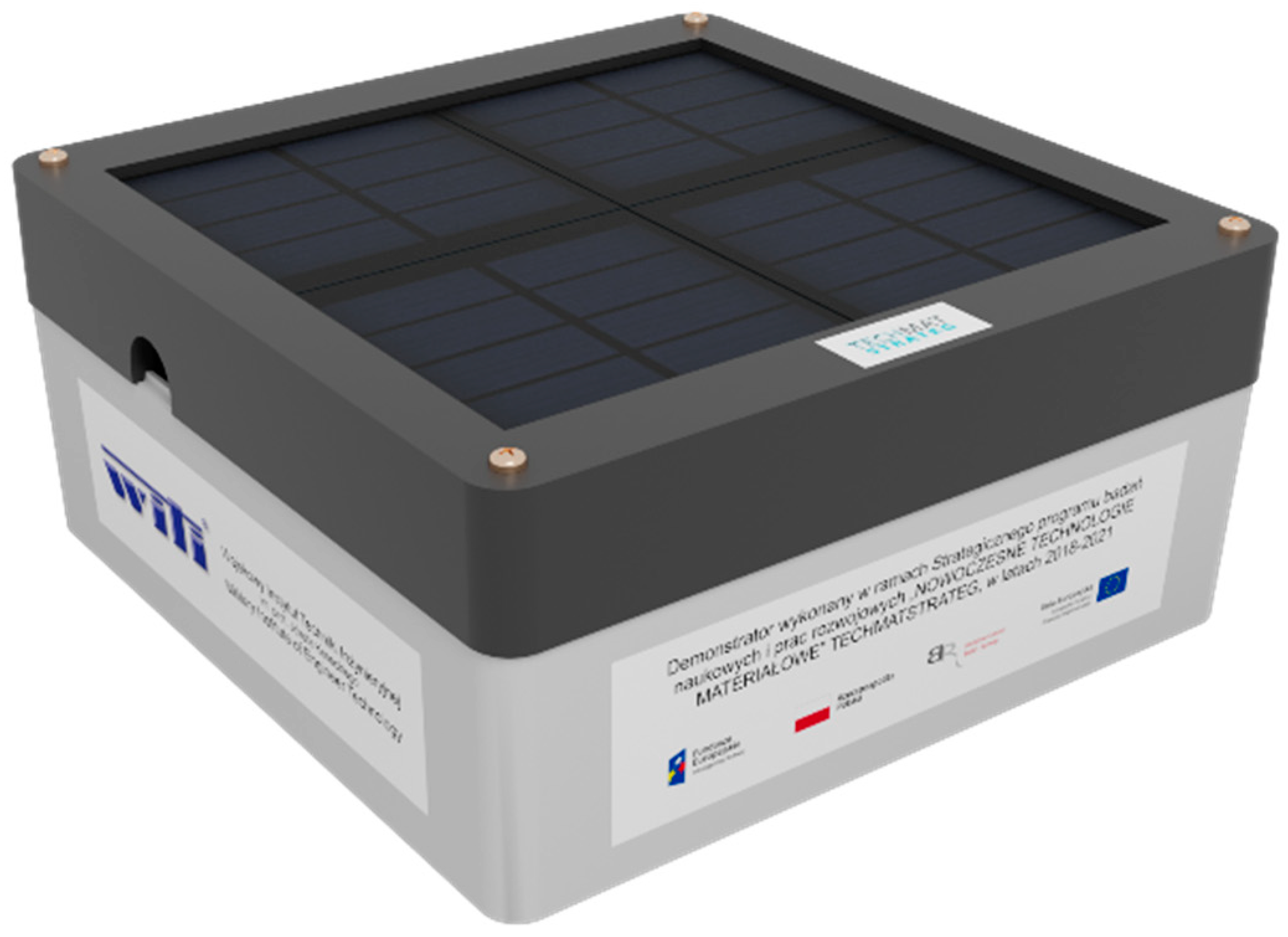
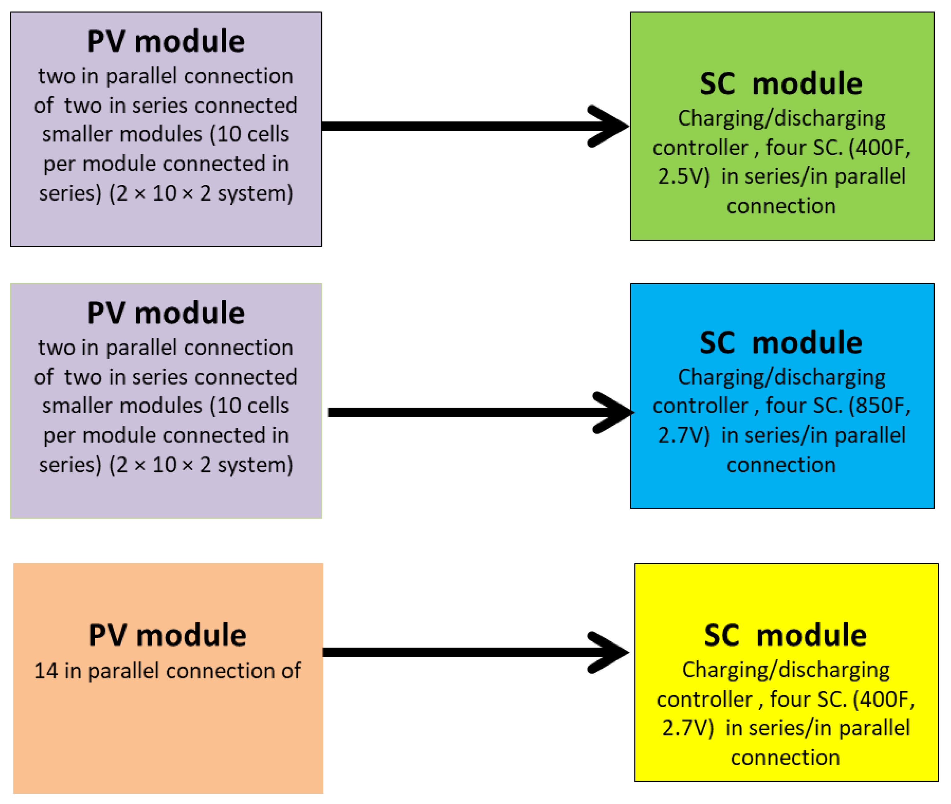
  • Construction of three fully functional demonstrators of energy storage system based on supercapacitors and silicon solar cells in various architectures (Scheme 1).
  • Experimental measurements of the properties of individual elements contained in three types of demonstrators, including current–voltage characteristics of photovoltaic systems and charging and discharging characteristics of supercapacitors.

2. Experimental

2.1. Materials

Silicon solar cells were received from the Soltec shop (Warszawa, Poland), while the supercapacitors were obtained from Eaton (Cleveland, OH, USA).
The crucial parameters of the investigated supercapacitors used in the energy storage system in this work are presented in Supporting Information in Table S1 together with equivalent circuits of supercapacitors presented in Figure 1.

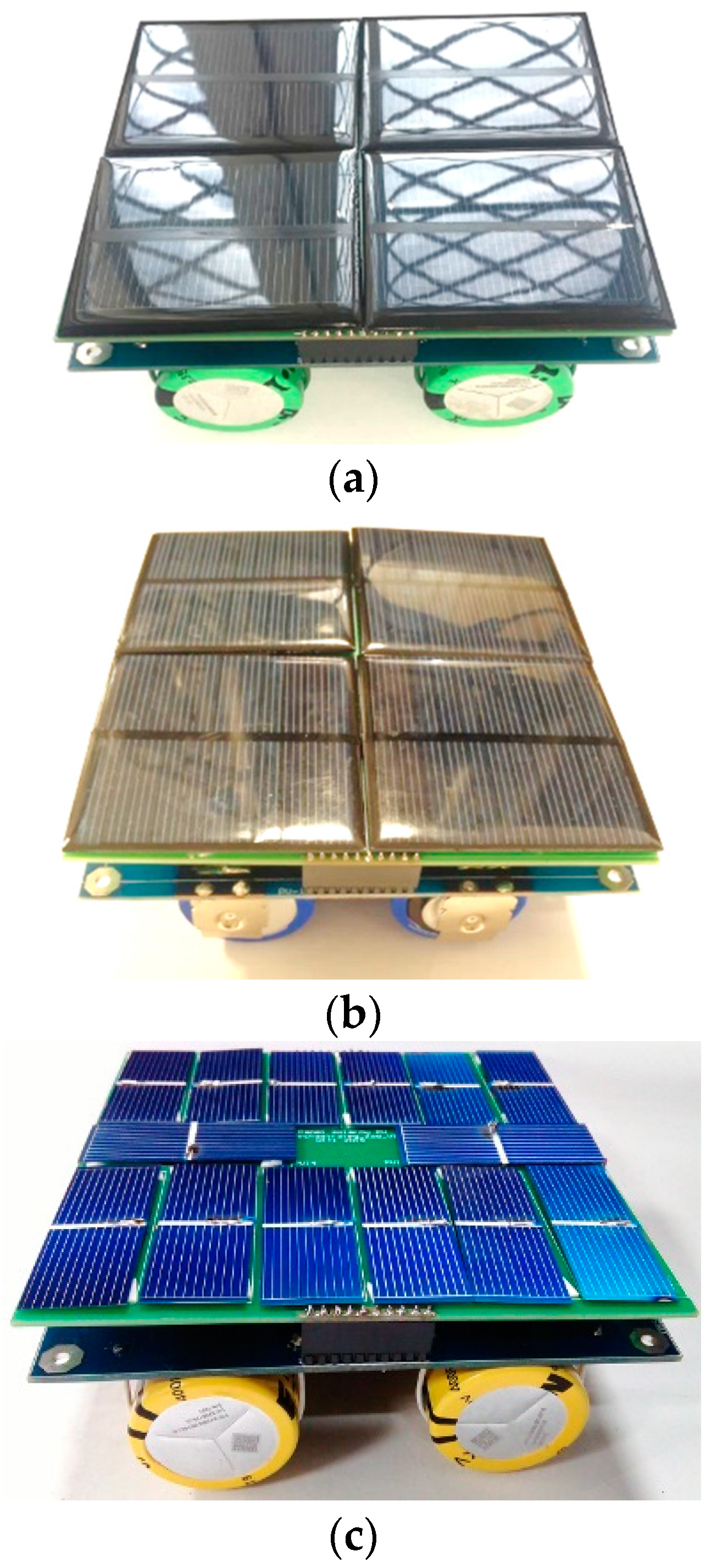
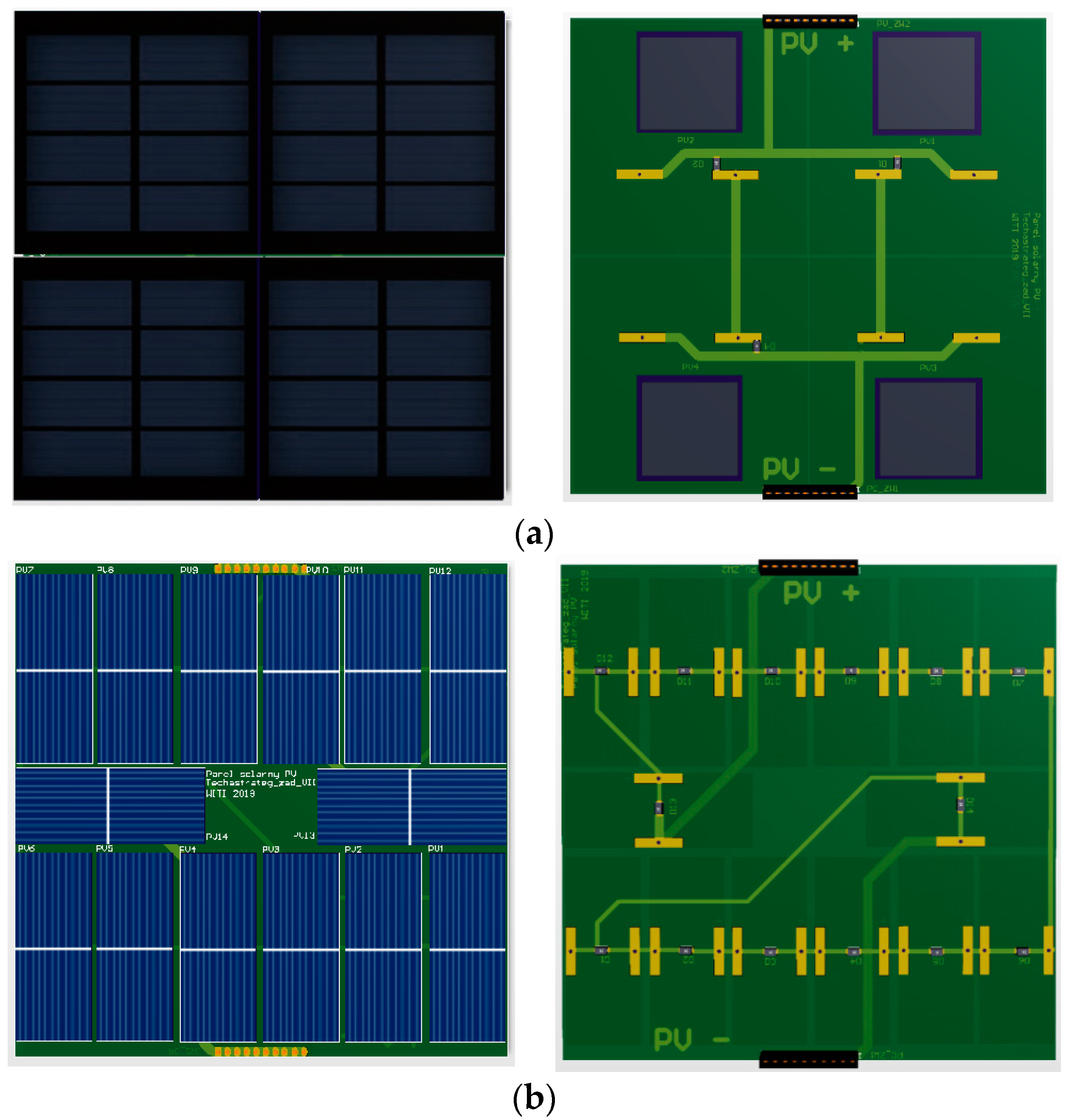
2.2. Energy Storage Systems Constructions

In our work, we constructed energy storage systems built on silicon-based solar cells with dimensions not exceeding 150 mm × 150 mm and power conversion efficiency PCE ≥ 14% and supercapacitors as is presented in Figure 2 [19].
In this work, we constructed three fully functional demonstrators of an energy storage system based on supercapacitors and silicon solar cells, presented in detail:
(a)
40 PV cells connected in series–in parallel in a 2 × 10 × 2 system with parameters of open circuit voltage Voc = 12.5 V and short-circuit current Isc = 155 mA in two pieces.
(b)
14 PV cells connected in series in a 14 × 1 system with parameters of open circuit voltage Voc = 7.95 V and short-circuit current Isc = 360 mA in two pieces.
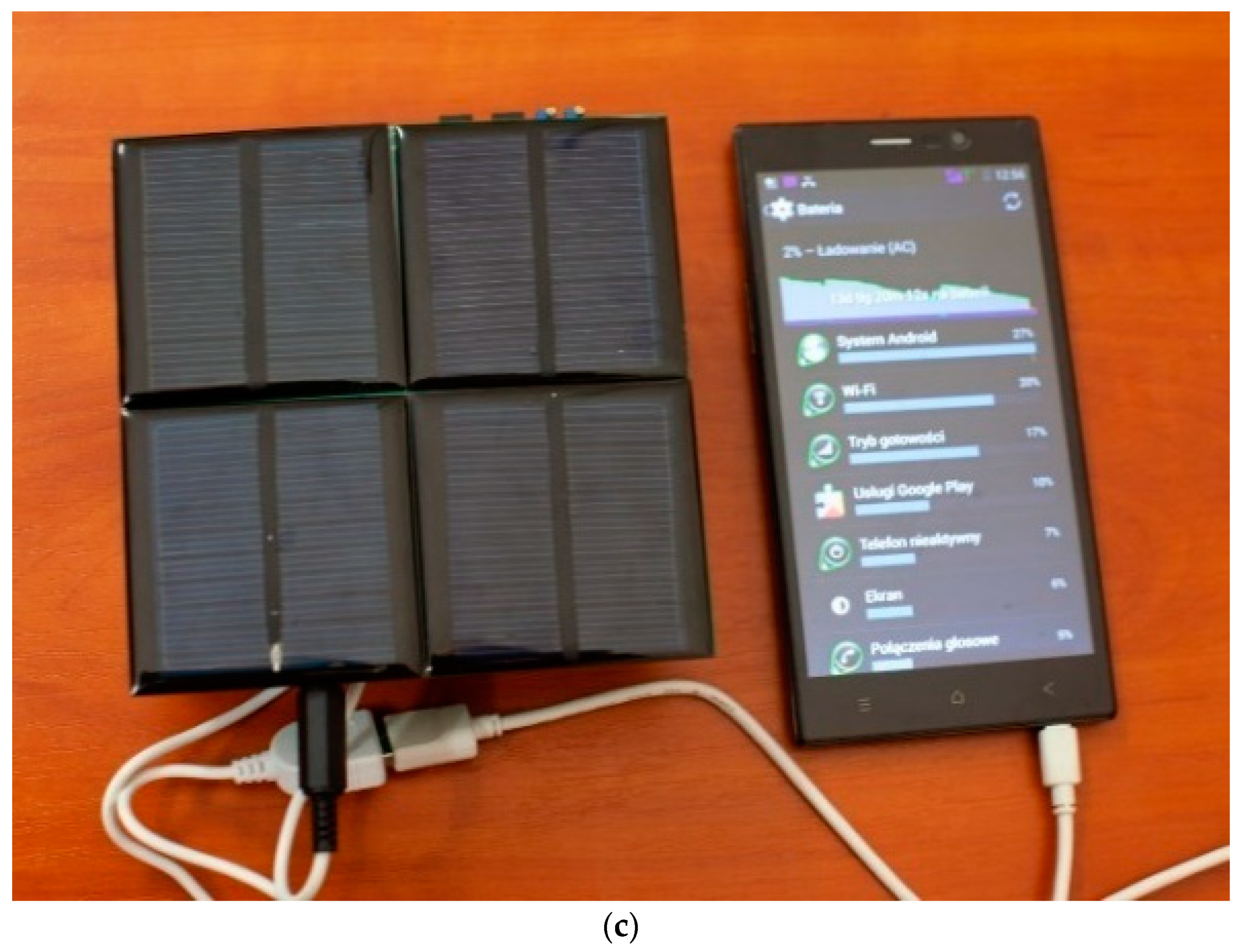
(c)
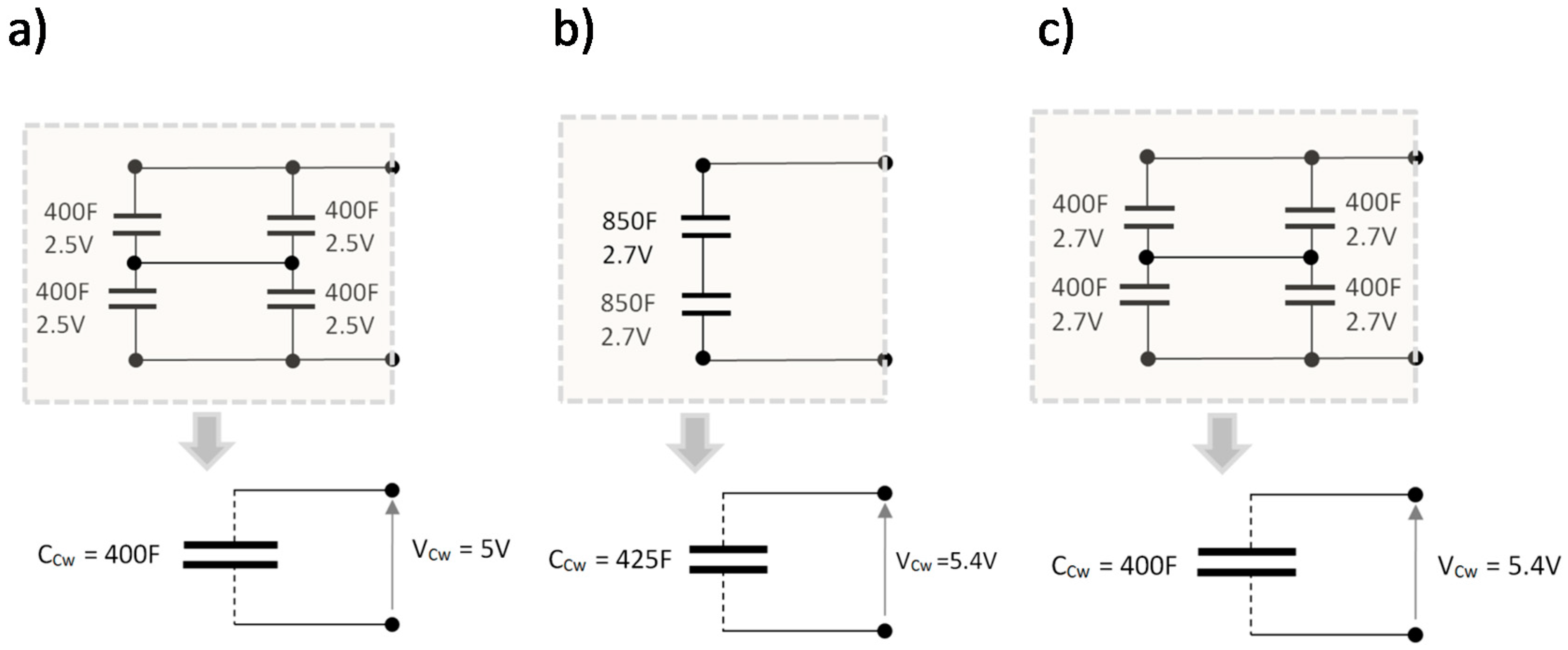
Circuit board of the power source block, charging voltage control system, and supercapacitors system with a total capacity of CSC = 400 F and operating voltage VCw = 5 V.
(d)
Power source block board, charging voltage control system, and supercapacitors system with a total capacity of CSC = 425 F and operating voltage VCw = 5.4 V.
(e)
Power source block board, charging voltage control system, and supercapacitors system with a total capacity of CSC = 400 F and operating voltage VCw = 5.4 V.

2.3. Characterization Methods

The measurement of the current–voltage (I–V) characteristics of the photovoltaic cells was made on the test bench shown in Supporting Information in Figure S1. It consists of the SS150AAA solar radiation simulator coupled with the I–V Tracer SS IV CT-02 system for measuring the I–V characteristic integrated with a Keithley Sourcemeter SM2401. Using the solar radiation simulator SS150AAA, the I–V characteristics of commercial solar elements were performed including:
(a)
A single cell with 50 mm × 20 mm photosensitive field dimensions, Figure S1a;
(b)
A set of 10 cells in series with a total dimension of the photosensitive field 65 mm × 65 mm, Figure S1b.
Three pieces of each of the tested cells (modules) were tested, and then the average values of parameters were determined and the average I–V characteristics were plotted. Table 1 presents a summary of average parameters from the silicon solar cells (modules) tested, and Figure S1 presents the I–V characteristics at the intensity of light radiation 974 W/m2 and ambient temperature during measurements T = 25.5 °C.

3. Results and Discussions

3.1. Theoretical Concepts

In the first phase of the conceptual work, the energy value of the energy storage in the form of a series or series/parallel connection of supercapacitors was calculated:
E = V C w 2 C w 2
where:
  • VCw—voltage to which the supercapacitor set is charged;
  • Cw—resultant capacity of the supercapacitors’ set;
for supercapacitors connected in series:
C w = C s c n
where:
  • CSC—capacity of a single supercapacitor;
  • n—amount of supercapacitors.
and for supercapacitors connected in parallel:
C w = C s c * n
Table 2 shows the results of calculations for various supercapacitor configurations in series and in parallel.
As it can be seen from Table 2, the amount of supercapacitors in the energy storage systems linearly affects the amount of energy stored in it. The only difference is that in the series connection, the operating voltage of the whole system increases, and in the parallel connection, the current does, as expected. This is important from the receiver point of view, which is characterized by a specific voltage (VCw) and operating current (ICw). Hence, the most suitable connection system to reach 5 V of working voltage for supercapacitors will be an energy storage composed of four supercapacitors (parallel connection of two in series supercapacitors) or two supercapacitors in series with twice the capacity.
It should be noted that in series parallel arrangement Figure 1b with the same values, the equivalent ESRCw (equivalent series resistance) value of the energy storage will have approximately the ESRsc of a single supercapacitor, whereas the equivalent resistance in series arrangement will be approximately two times the ESRsc value of a single supercapacitor. This is very important from the point of view of the current efficiency of the energy storage in the event of loading it with a high-current pulse receiver.

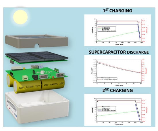
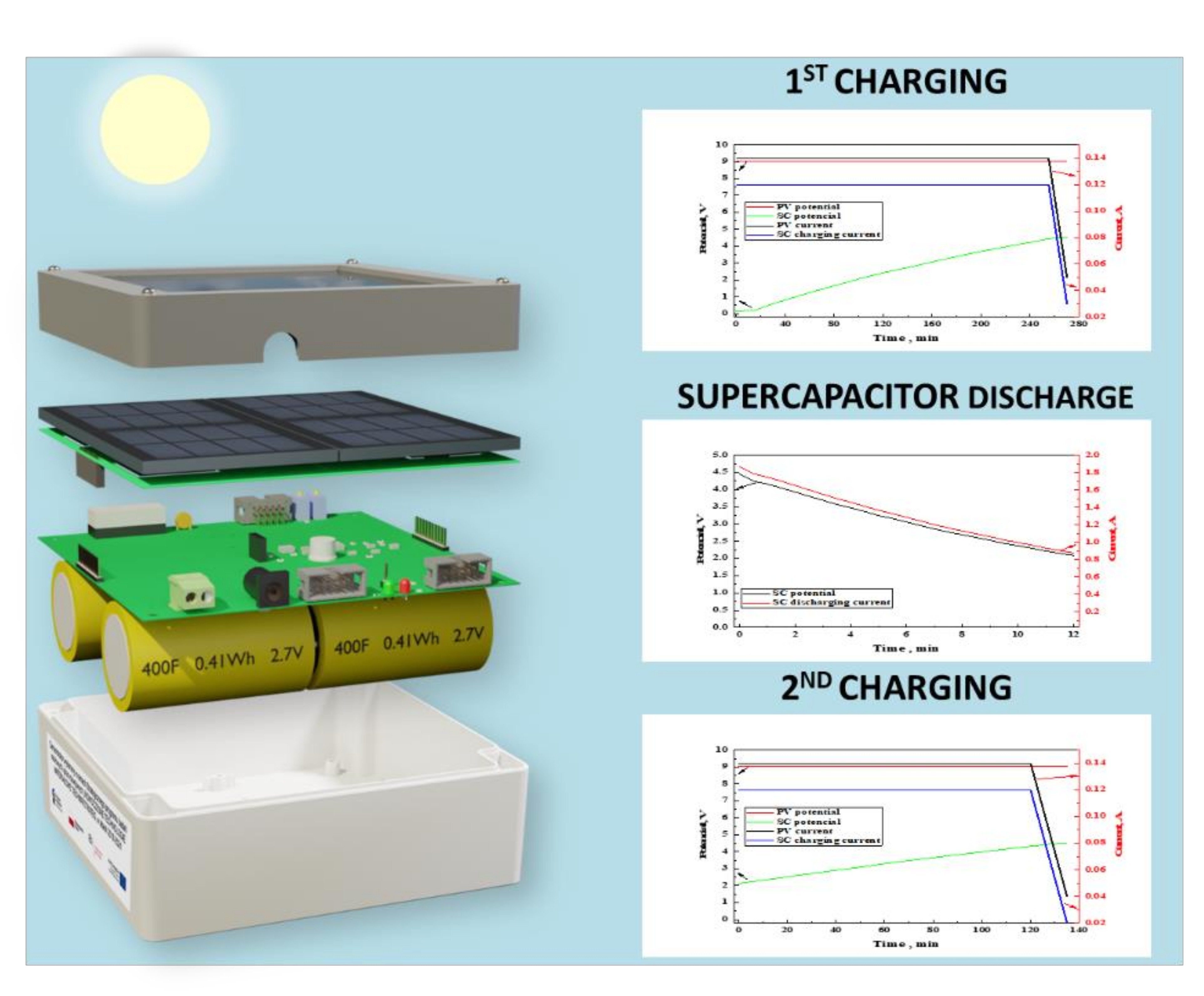
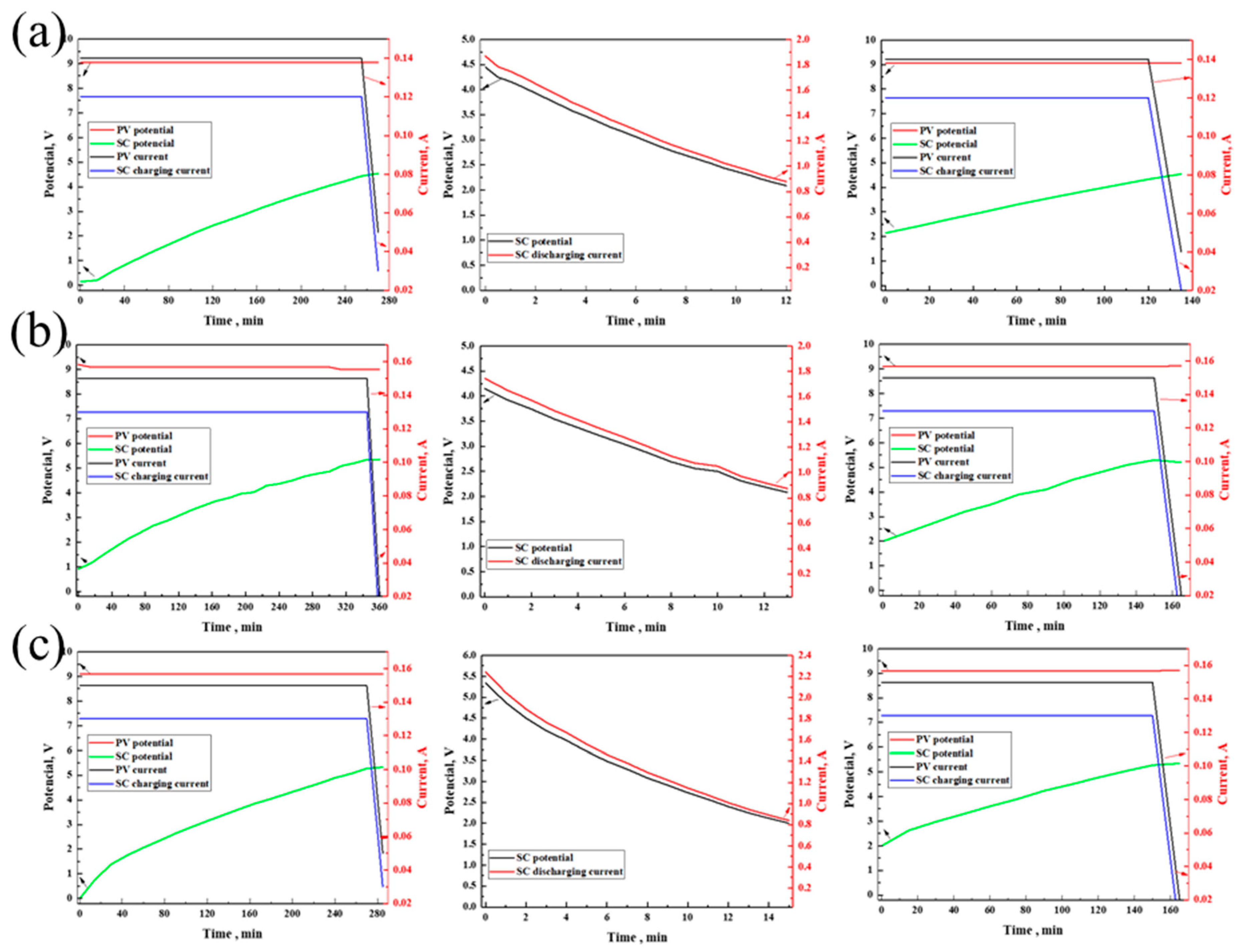
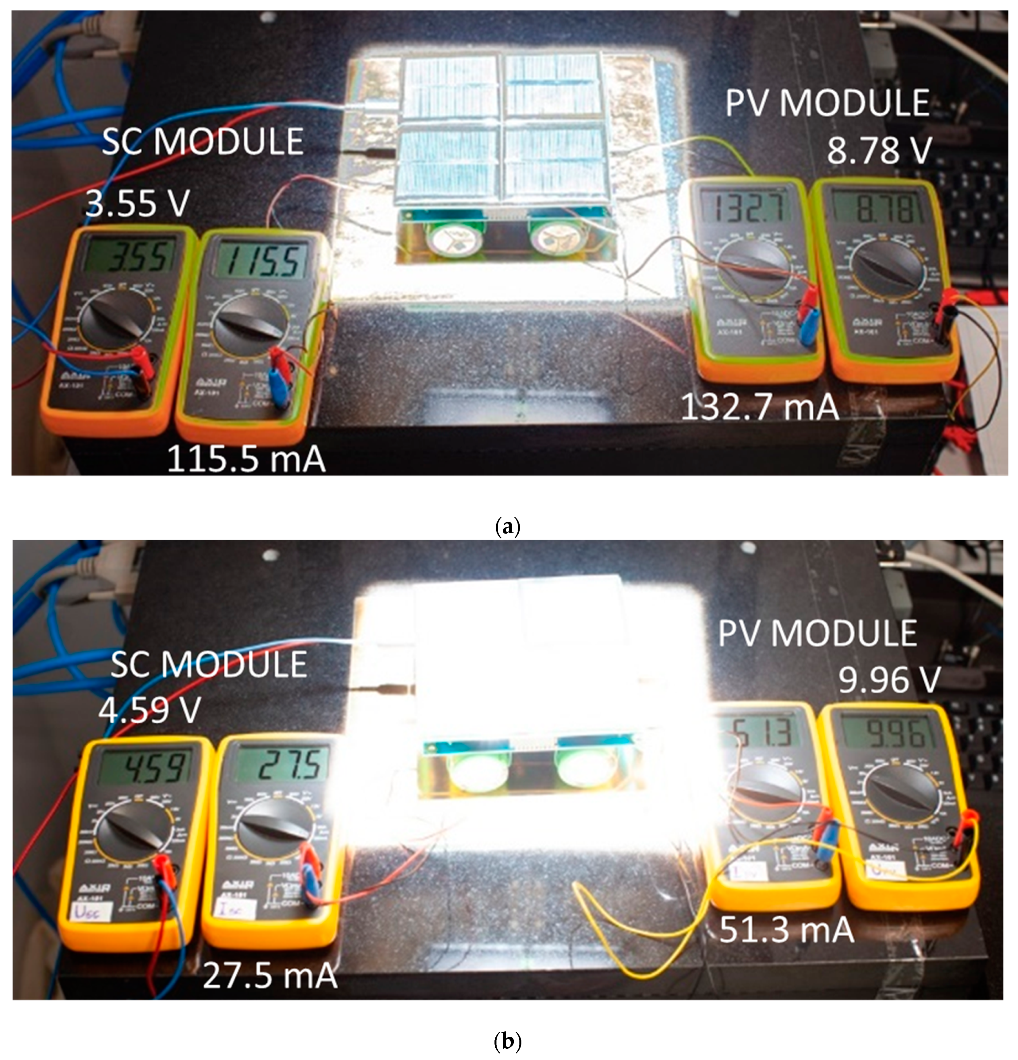
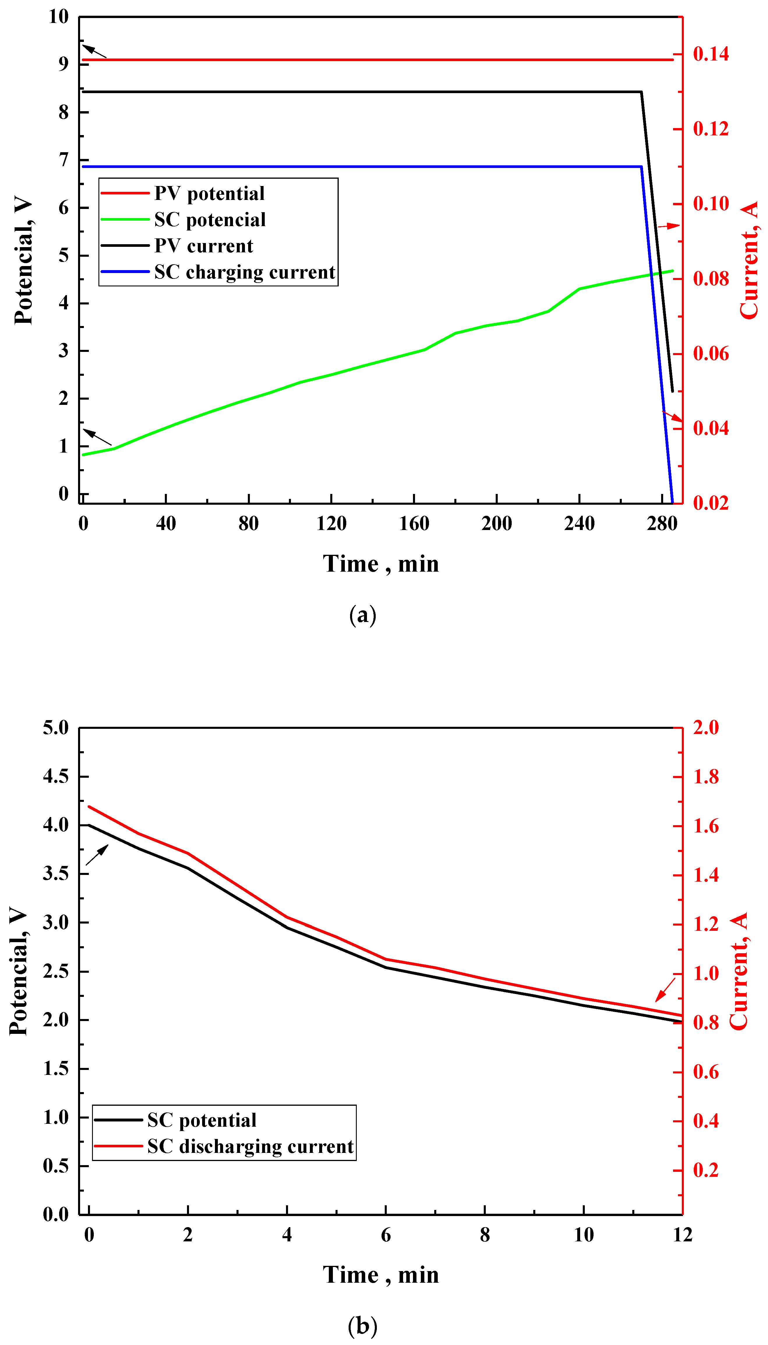
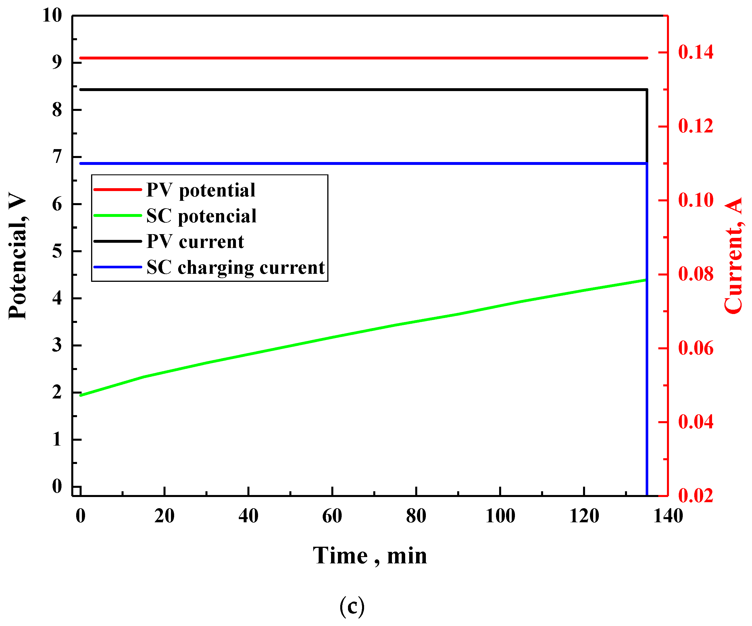
3.2. Silicon Solar Cells to Supercapacitors Charging Efficiency Optimization

In this work, as it was mentioned previously, three demonstrators based on silicon solar cells and supercapacitors were constructed and analyzed in detail. In the first demonstrator, the photovoltaic panel (PV) consists of 40 cells connected in series–in parallel in a two in parallel connection of two in series connected smaller modules (10 cells per module connected in series) (2 × 10 × 2 system) and a block of current source, voltage control system, and four supercapacitors in series/in parallel with a capacity of CSC = 400 F each and operating voltage VSC = 2.5 V each was constructed as presented in Figure 3a. In the first demonstrator, the supercapacitors with a capacity of CCw = 400 F and a working voltage of VCw = 5 V were used. In the second demonstrator, the PV panel in a system of 40 cells (connected in series–in parallel in a 2 × 10 × 2 system) and a block power source, voltage control system, and two supercapacitors in series with a capacity of CSC = 850 F and operating voltage VSC = 2.7 V each were created as is shown in Figure 3b. In the second demonstrator, the supercapacitor with a capacity of CCw = 425 F and a working voltage of VCw = 5.4 V was applied. In the third demonstrator, PV cells in a system of 14 cells connected in series in a system of 14 × 1 and four supercapacitors with a capacity of CSC = 400 F and operating voltage VSC = 2.7 V were created (see Figure 3c), giving CCw = 400 F and VCw = 5.4 V for supercapacitors’ connection.
Visualization of a printed electric board with photovoltaic elements in parallel–series connection, and series connection of 14 PV elements is presented in Figure 4.
It should be stressed that before the assembly of each element of the constructed energy storage systems, each element was tested in terms of compliance with the schematic diagrams presented in Supporting Information in Figures S2 and S3, and quality of workmanship was tested by checking the characteristic dimensions of the circuit, as well as the absence of impurities on the surface such as machining residues, dust, and laminate shreds. A visual inspection was also carried out on the contact pads in terms of the quality of the solder layer applied and the lack of fingerprints on them. The quality of the protective layer (solder mask) was also checked, whether it had a uniform appearance, was free from scratches, discoloration and lumens, and most importantly, whether it was not moved, i.e., it is not on the soldering pads. After confirming that the tiles were free from defects and their quality did not raise any objections, the elements were connected toward created energy storage systems. Engineering details of all created energy storage systems are presented in Supporting Information in Figures S4 and S5 (demonstrator no. 1), Figures S6 and S7 (demonstrator no. 2), and Figure S8 and Figure S9 (demonstrator no. 3).
For all constructed energy storage systems, the selected electrical experiments were made in two stages:
  • Measurements of current–voltage characteristics of the assembled PV panel,
  • Measurements of charging, discharging, and recharging characteristics of supercapacitors.
The obtained results are presented in Table 3.
The tested PV panels were measured three times; then, the average values of parameters were determined and the average current–voltage characteristics were plotted. The results of the average measurements are shown in Figure S10. All investigated PV solar cells exhibited good photovoltaic parameters suitable for construction of energy storage systems based on supercapacitors. In the next step of our work, we tested three demonstrators under charging supercapacitors to VCw, under discharge of supercapacitors to VCw = 2 V, and under second charging supercapacitors to VCw (see Figure 5).
Test results of supercapacitor charging time (background = 260 min) shown in Figure 5 (left side) indicate that the system has been designed correctly and the constructed demonstrator guarantees the correct conditions for integration with the PV panel part of the system, power source blocks, voltage control system, and supercapacitor charging system.
The discharge characteristics of supercapacitors determine how much energy we can recover from charged supercapacitors, assuming that the voltage drop on them will not be lower than 2 V (important when we want to use the voltage conversion system as a coupling between the supercapacitors and the load).
In cyclic operation, supercapacitors must be recharged from VCwmin = 2.2 V to VCwmax = 4.65 V (Figure 5). In other cases, the VCwmax value of Vload was used and the value of VCwmin was set as a fixed value for all cases (see Table 3). The recharging time is equal to 135 s and is 2.5 times shorter than the time of the first charge, and the energy supplied to the supercapacitors during charging is calculated according to the formula:
E r e = 1 2 ( V C w m a x     V C w m i n     ) 2 × C w
Hence, the efficiency of such a system when charging supercapacitors was found for demonstrator no. 1 at 0.76, according to the formula:
η d = E r e E r c     η d = 0.23   [ W h ] 0.3   [ W h ]     η d = 0.76
For demonstrators no. 2 and 3, the values of Ere ~0.21 Wh and 0.57 Wh, together with efficiency 0.93 and 0.92, respectively. The difference between the efficiency of demonstrator no. 1 to the other two can be explained by the type of used connections between the supercapacitor and the electronic module. In the case of the first demonstrator, supercapacitors were placed in a spring-type holder, whereas the second and third demonstrators were soldered to the electronic module. The spring-like connection is predetermined by the manufacturer features. Use of different connections in device no. 2 and 3 were also possible due to its specific construction. Spring connections did not allow it to maintain a good connection, resulting in the increase of internal resistance.
The voltage and current values during and after charging the supercapacitor module are presented in Figure 6 together with an example of charging a mobile phone using our energy storage system.
The performance of the energy storage unit was tested after three months from the initial experiment. No significant changes were observed (Figure 7). Only a small deviation from previous results was noticed, caused mainly by soldering additional wires used to register the level of the supercapacitor charge on the electric board.

4. Conclusions

In summary, three demonstrators of energy storage systems based on various architectures of silicon solar cells and supercapacitors were constructed and analyzed in detail, both theoretically and experimentally. In the first demonstrator, the system of 40 PV cells (connected in series–in parallel in a 2 × 10 × 2 system) and a block of current source, voltage control system, and four supercapacitors in series/in parallel with a capacity of CSC = 400 F was constructed. In the second demonstrator, the system of 40 PV cells connected in series–in parallel in a 2 × 10 × 2 system and a block of a power source, voltage control system, and two supercapacitors in series with a capacity of CSC = 850 F was created. In the third demonstrator, the system of 14 PV cells connected in series in a system of 14 × 1 and four supercapacitors with a capacity of CSC = 400 F was created.
Our results showed that among modification of amount and configurations of used PV cells and supercapacitors, it is possible to obtain a demonstrator with efficiency as high as 0.93 (demonstrator no. 2).

Supplementary Materials

The following are available online at https://www.mdpi.com/1996-1073/13/15/3867/s1, Figure S1: I-V characteristics of: (a) PV cell with size of 50 mm × 20 mm and (b) PV module with size of 65 mm × 65 mm; Figure S2: Schematic diagrams of PV panels: (a) photovoltaic cells in a 2 × 10 × 4 series-parallel arrangement; (b) 14 solar cells in series; Figure S3: Schematic diagram of the power source block, voltage control system and supercapacitors; Figure S4: View of assembled PCB of first demonstrator-photovoltaic cells in a system of 40 cells connected in series in parallel in a 2 × 10 × 2 system: (a) page of elements; (b) print page; Figure S5: View of assembled elements: (a) a block of a power source, a voltage control system and (b) four supercapacitors with a capacity of CSC = 400 F, operating voltage VSC = 2.5 V; Figure S6: View of assembled PCB of second demonstrator—photovoltaic cells in a system of 40 cells connected in series in parallel in a 2 × 10 × 2 system: (a) page of elements; (b) print page; Figure S7: View of assembled PCB of second demonstrator: power source block, voltage control system and two supercapacitors with capacity CSC = 850 F and operating voltage VSC = 2.7 V, (a) page of elements; (b) print page; Figure S8: View of assembled PCB of third demonstrator—photovoltaic cells in a system of 14 cells connected in series in a 14 × 1 system: (a) page of elements; (b) print page; Figure S9: View of assembled PCB of third demonstrator—current source block, voltage control system and four supercapacitors with CSC = 400 F capacity and VSC = 2.7 V operating voltage: (a) page of elements; (b) print page; Figure S10: Average voltage and current characteristics of a PV panel with the MPP optimal operating point marked at illumination ~990 W/m2 and ~21 °C for: (a) demonstrator no. 1 (Voc = 12.45 V, Isc = 155.76 mA, FF = 65%, PCE = 8.94%), (b) demonstrator no. 2 (Voc = 12.34 V, Isc = 212.67 mA, FF = 65%, PCE = 11.85%), (c) demonstrator no. 3 (Voc = 7.95 V, Isc = 359.33 mA, FF = 69%, PCE = 14.65 %), Table S1: A summary of crucial parameters of supercapacitors used in energy storage system.

Author Contributions

I.P., conceptualization, investigation, and methodology of energy storage systems based on PV module and supercapacitors; A.I. and K.A.B., analysis of results, writing—original draft preparation, and writing—review and editing. All authors have read and agreed to the published version of the manuscript.

Funding

This research was funded by the Polish National Centre of Research and Development grant number TECHMATSTRATEG1/347431/14/NCBR/2018.

Acknowledgments

The authors are grateful for financial support from the Polish National Centre of Research and Development (TECHMATSTRATEG1/347431/14/NCBR/2018). The authors thanks Piotr Otręba for print device housing using the 3D printer.

Conflicts of Interest

The authors declare no conflict of interest.

References

  1. Schmidt, D.; Hager, M.D.; Schubert, U.S. Photo-rechargeable electric energy storage systems. Adv. Energy Mater. 2016, 6, 1500369. [Google Scholar] [CrossRef]
  2. Chauhan, A.; Saini, R.P. A review on Integrated Renewable Energy System based power generation for stand-alone applications: Configurations, storage options, sizing methodologies and control. Renew. Sustain. Energy Rev. 2014, 38, 99–120. [Google Scholar] [CrossRef]
  3. Christen, T.; Ohler, C. Optimizing energy storage devices using Ragone plots. J. Power Sources 2002, 110, 107–116. [Google Scholar] [CrossRef]
  4. Roy, P.K.S.; Karayaka, H.B.; Yana, Y.; Alqudah, Y. Investigations into best cost battery-supercapacitor hybrid energy storage system for a utility scale PV array. J. Energy Storage 2019, 22, 50–59. [Google Scholar] [CrossRef]
  5. Thounthonga, P.; Chunkag, V.; Sethakul, P.; Sikkabut, S.; Pierfederici, S.; Davat, B. Energy management of fuel cell/solar cell/supercapacitor hybrid power source. J. Power Sources 2011, 196, 313–324. [Google Scholar] [CrossRef]
  6. Gunawardane, K. Capacitors as energy storage devices-simple basics to current commercial families. In Energy Storage Devices for Electronic Systems: Rechargeable Batteries and Supercapacitors; Academic Press: New York, NY, USA, 2015; pp. 137–148. ISBN 978-012408119-2. [Google Scholar]
  7. Beaudin, M.; Zareipour, H.; Schellenberg, A.; Rosehart, W. Energy Storage for mitigating the variability of renewable electricity sources, energy storage for smart grids. In Planning and Operation for Renewable and Variable Energy Resources (VERs); Academic Press: New York, NY, USA, 2015; pp. 1–33. ISBN 978-0-12-410491-4. [Google Scholar]
  8. Logerais, P.-O.; Riou, O.; Camara, M.A.; Durastanti, J.-F. Study of photovoltaic energy storage by supercapacitors through both experimental and modelling approaches. J. Sol. Energy 2013, 659014. [Google Scholar] [CrossRef] [Green Version]
  9. Kularatna, K.M.; Round, W.H. Supercapacitor energy storage in solar application: A design approach to minimize a fundamental loss issue by partitioning the load and the storage device. In Proceedings of the 2015 IEEE 24th International Symposium on Industrial Electronics (ISIE), Buzios, Brazil, 3–5 June 2015; pp. 1308–1312, ISBN 978-1-4673-7554-2. [Google Scholar]
  10. Li, L.; Huang, Z.; Li, H.; Lu, H. A high-efficiency voltage equalization scheme for supercapacitor energy storage system in renewable generation applications. Sustainability 2016, 8, 548. [Google Scholar] [CrossRef] [Green Version]
  11. Fahmi, M.I.; Rajkumar, R.K.; Arelhi, R.; Isa, D. Study on the effect of supercapacitors in solar PV system for rural application in Malaysia. In Proceedings of the 2015 50th International Universities Power Engineering Conference (UPEC), Stoke on Trent, UK, 1–4 September 2015; ISBN 978-1-4673-9682-0. [Google Scholar]
  12. Andreotti, A.; Mottola, F.; Pagano, M.; Velotto, G. Design of ultracapacitor based filter for isolated PV source feeding pulsing load. Electr. Power Syst. Res. 2008, 78, 1038–1046. [Google Scholar] [CrossRef] [Green Version]
  13. Bergonzini, C.; Brunelli, D.; Benini, L. Comparison of energy intake prediction algorithms for systems powered by photovoltaic harvesters. Microelectron. J. 2010, 41, 766–777. [Google Scholar] [CrossRef]
  14. Hande, A.; Polk, T.; Walker, W.; Bhatia, D. Indoor solar energy harvesting for sensor network router nodes. Microprocess. Microsyst. 2007, 31, 420–432. [Google Scholar] [CrossRef]
  15. Janek, A.; Trummer, C.; Steger, C.; Weiss, R.; PreishuberPfluegl, J.; Pistauer, M. Simulation based verification of energy storage architectures for higher class tags supported by energy harvesting devices. Microprocess. Microsyst. 2008, 32, 330–339. [Google Scholar] [CrossRef]
  16. Sahin, M.E.; Blaabjerg, F. A hybrid PV-battery/supercapacitor system and a basic active power control proposal in MATLAB/Simulink. Electronics 2020, 9, 129. [Google Scholar] [CrossRef] [Green Version]
  17. Westover, A.S.; Share, K.; Carter, R.; Cohn, A.P.; Oakes, L.; Pint, C.L. Direct integration of a supercapacitor into the backside of a silicon photovoltaic device. Appl. Phys. Lett. 2014, 104, 213905. [Google Scholar] [CrossRef]
  18. Vega-Garita, V.; Ramirez-Elizondo, L.; Narayan, N.; Bauer, P. Integrating a photovoltaic storage system in one device: A critical review. Prog Photovolt. Res. Appl. 2019, 27, 346–370. [Google Scholar] [CrossRef] [Green Version]
  19. Plebankiewicz, I.; Bogdanowicz, K.A.; Iwan, A. Electronic System for Charger of Supercapacitors from Solar Cells. Polish Patent Application P.32868, 10 February 2020. [Google Scholar]
Scheme 1. Graphical representation of different architecture studied in the current work.
Energies 13 03867 sch001
Figure 1. Equivalent circuits of supercapacitors presented in Table S1: XB3560-2R5407-R (a), SCCY1AB857SLBLE (b), and XV3560-2R7407-R (c).
Energies 13 03867 g001
Figure 2. Photograph of a constructed demonstrator of an energy storage system based on silicon solar cells and supercapacitors [19].
Energies 13 03867 g002
Figure 3. Images of three types of created demonstrators of energy storage systems based on: (a) demonstrator no. 1, (b) demonstrator no. 2, and (c) demonstrator no. 3.
Energies 13 03867 g003
Figure 4. Visualization of printed electric board with photovoltaic elements. (a) PV system in parallel–series connection, (b) series connection of 14 PV elements in top view (left side) and bottom view (right side).
Energies 13 03867 g004
Figure 5. Characteristics of three demonstrators under charging supercapacitors to VCw, under discharge of supercapacitors to V = 2 V, and under second charging supercapacitors to VCw from top to bottom for (a) demonstrator no. 1, (b) demonstrator no. 2, and (c) demonstrator no. 3.
Energies 13 03867 g005
Figure 6. Images of voltage and current values during charging (a) the supercapacitor module and after charging (b) the supercapacitor module together with an example of charging a mobile phone using our energy storage system (c).
Energies 13 03867 g006aEnergies 13 03867 g006b
Figure 7. Characteristics of demonstrator no. 1 under charging supercapacitors to VCw (a), under discharge of supercapacitors to V = 2 V (b), and under second charging supercapacitors to VCw after three months (c).
Energies 13 03867 g007aEnergies 13 03867 g007b
Table 1. Summary of average parameters from the silicon solar cells (modules) tested.
ParameterSymbolTotal Area
50 mm × 20 mm65 mm × 65 mm
Short circuit currentIsc355.3 (mA)56.7 (mA)
Open circuit currentVoc597.3 (mV)6.4 (V)
Maximum currentImax322.9 (mA)72.4 (mA)
Maximum voltageVmax465.4 (mV)4.8 (V)
Maximum powerPmax150.3 (mW)345.2 (mW)
Fill factorFF0.70.7
Photovoltaic conversion efficiencyPCE15.4%8.3%
Series resistanceRs205.6 (mΩ)268.6 (Ω)
Shunt resistanceRsh187.9 (Ω)18.0 (kΩ)
Table 2. Selected electrical parameters for various supercapacitor configurations in series and in parallel.
No. of Capacitors,
n
Series ConnectionParalel Connection
Working Voltage
VCw, (V)
Final Capacity
Cw = CSC/n, (C)
Energy
E, (Ws)
Working Voltage
VCw, (V)
Final Capacity
Cw = CSC × n, (C)
Energy
E, (Ws)
12.5400.0012502.54001250
25200.0025002.58002500
37.5133.3337502.512003750
410100.0050002.516005000
512.580.0062502.520006250
61566.6775002.524007500
Table 3. Selected electrical parameters of all investigated energy storage systems.
Selected ParametersSymbolDemonstrator no. 1Demonstrator no. 2Demonstrator no. 3
Rated voltage of supercapacitor set VCw5.0 V5.4 V5.4 V
Rated capacity of supercapacitor set CCw400 F425 F400 F
The theoretical amount of energy stored E 1.39 Wh1.72 Wh1.56 Wh
First charge timetn255 min345 min270 min
Efficiency of system during the first charging of supercapacitors η r 0.200.200.36
Possible energy to recoverEre0.23 Wh0.21 Wh0.57 Wh
Supercapacitor set voltage after connecting the load Rload = 2.4 Ω during tnVloadc4.65 V 4.15 V5.3 V
Discharge time to voltage Vload = 2 Vtr720 s780 s900 s
Energy supplied to supercapacitors during rechargingErc0.3 Wh0.22 Wh0.61 Wh
Top up timetn135 min165 min150 min
The efficiency of system when charging supercapacitors η d 0.760.930.92

