Review

Power System Stability with Power-Electronic Converter Interfaced Renewable Power Generation: Present Issues and Future Trends

by
Lasantha Meegahapola
1,*,
Alfeu Sguarezi
2,
Jack Stanley Bryant
1,
Mingchen Gu
1,
Eliomar R. Conde D.
2 and
Rafael B. A. Cunha
3
1
Electrical and Biomedical Engineering, School of Engineering, RMIT University, Melbourne 3001, Australia
2
Center for Engineering, Modeling and Applied Social Sciences, Federal University of ABC (UFABC), Santo André 09210-580, SP, Brazil
3
Polytechnic School, University of São Paulo (USP), São Paulo 05508-010, SP, Brazil
*
Author to whom correspondence should be addressed.
Energies 2020, 13(13), 3441; https://doi.org/10.3390/en13133441
Submission received: 1 June 2020 / Revised: 22 June 2020 / Accepted: 30 June 2020 / Published: 3 July 2020
(This article belongs to the Section F: Electrical Engineering)

Abstract

:
The energy sector is currently undergoing a rapid transformation with the integration of power electronic converter (PEC)-interfaced renewable energy sources (RES), such as wind and solar photovoltaic (PV) systems, at both the transmission and distribution networks. Power system stability has been significantly influenced by this power grid transformation. This paper comprehensively reviews major power system stability issues affected due to large-scale integration of PEC-interfaced RES in power grids, with some example case studies relevant for each stability category. According to the review, stability issues are mainly originating from reduction in synchronous inertia, reduction in reactive power reserve, low short-circuit strength of the power network, and fault ride-through (FRT) strategy/capability of the PEC-interfaced RES. Decrease in synchronous inertia could affect both the rotor angle stability and the frequency stability, while decrease in short-circuit strength and reactive power reserve could cause voltage stability and rotor angle stability issues in power networks. Sub-synchronous control interactions are also receiving a lot of attention by the power industry due to increasing oscillatory stability incidents reported in power networks with PEC-interfaced RES. FRT capabilities/strategies of PEC-interfaced RES are also playing a pivotal role in power grid stability due to its influence on active and reactive power, hence more emphasis should be placed on FRT schemes of PEC-interfaced RES, since future power grids are expected to operate with 100% PEC-interfaced generation sources. Stability improvement strategies could be implemented to address multiple stability issues in PEC-interfaced power networks; however, rigorous stability studies are required to identify the optimal conditions to implement these improvement strategies. Furthermore, ongoing structural changes in power grids to accommodate remotely sited PEC-interfaced RES are also influencing the stability of power grids. Therefore, all these factors must be carefully considered by system operators when planning and operating power grids in a secure and stable manner with high penetration levels of PEC-interfaced RES.

Graphical Abstract

1. Introduction

Over the past two decades (2000–2019), 1200 GW of power electronic converter (PEC) interfaced renewable energy sources (i.e., wind and solar-PV) [1,2] were integrated to power grids around the world, while making significant changes to power grid structure/architecture, operation and control procedures [3]. Increased pressure to reduce green-house gas emissions from power generation, advancement of power electronic technology, increase in the energy demand, and depletion of fossil-fuel energy resources are the major catalysts for the rapid increase of the PEC-interfaced renewable energy sources (RES) in power grids [4,5]. Currently, many countries (e.g., Denmark, Ireland) and regions (e.g., South Australia, Texas) are reporting very high instantaneous penetration levels of PEC-interfaced RES, and some cases penetration levels are even higher than 100% (penetration level is defined based on the load demand of the region/ country and excess power will be exported to neighboring regions and countries) during system operation [6]. However, some countries are adopting more conservative approaches to dispatching PEC-interfaced RES (non-synchronous generation) during system operation, by specifically considering stability boundaries in dispatch algorithms. For example, EirGrid (Republic of Ireland system operator) is systematically increasing their instantaneous PEC-interfaced RES power penetration by thoroughly evaluating stability boundaries in the Irish power grid.
Aforementioned, power system stability is one of the critical aspects in power system operation. System operators always keep a track on system stability via supervisory control and data acquisition (SCADA) systems or using various real-time monitoring tools based on synchrophasor technology [7]. These stability tools continually monitor system voltages, frequency, rotor-angles of synchronous machines, and power transfer capability between certain regions of the network [7]. In addition, with high penetration of PEC-interfaced renewable power generation, various advanced indices have been proposed and these indices are used by system operators to maintain power grid stability [8]. For example, in the Electric Reliability Council of Texas (ERCOT), the system operator is monitoring synchronous inertia in real-time and uses it as a critical indicator for frequency stability [9]. Moreover, additional operational constraints are applied by power grid operators to ensure stability during high renewable power penetration levels. For example, the Republic of Ireland grid operator, EirGrid, is using the non-synchronous generation, and operational limit for inertia as system operation constraints [8,10]. Similarly, in South Australia, synchronous inertia levels are strictly maintained via dispatch algorithms for secure and stable system operation [11]. These practical examples highlight the importance of power system stability for power grids operating with high penetration levels of PEC-interfaced RES.
Furthermore, with the large-scale integration of PEC-interfaced renewable power generating plants, power networks are undergoing significant structural changes. More specifically, high voltage direct current (HVDC) links are constructed to transmit power generated from remotely sited wind and solar-PV plants to the AC network [12,13]. These structural changes have evolved into hybrid AC/DC power grids, hence stability of the emerging hybrid AC/DC power grids is an important aspect in regards to future power grids [14]. In addition, the distribution grid is also increasingly adopting DC technology due to increased penetration of PEC-interfaced small-scale solar-PV systems and DC loads [15]. Therefore, these structural changes are also making significant changes in the power system stability paradigm.
The aim of this paper is to critically review the impact on various stability aspects due to PEC-interfaced renewable power integration into power systems and to shed-light on the future trends in power system stability. This paper is organized as follows: Section 2 briefly outlines the major stability issues affected by PEC-interfaced renewables and changes resulted in the power system dynamic timeframes due to PEC-interfaced renewables. Rotor angle and small-signal stability issues are reviewed in Section 3. Section 4 discusses the impact on frequency stability with PEC-interfaced RES and also reviews various methods reported in the literature on frequency stability improvement with PEC-interfaced generation sources. Voltage stability issues with PEC-interfaced generation are exemplified in Section 5. Sub-synchronous resonance and oscillatory stability issues are delineated in Section 6. The PEC-interfaced RES fault ride-through (FRT) strategies and their influence on stability are discussed in Section 7. In Section 8 the stability issues of the emerging hybrid AC/DC power grids are discussed with a classification on stability originating source. A discussion on future power grid stability with high penetration levels of PEC interfaced RES is presented in Section 9. Conclusions of the review are summarized in Section 10.

2. Stability Issues with PEC-Interfaced Renewable Power Generation

Renewable power generation was in existence for more than 100 years, more specifically synchronous generator-based hydropower generation was in existence for more than 100 years. In addition, induction generator-based grid-connected wind generation was in operation (i.e., fixed-speed wind farms) for more the 30 years, since the early stage of large-scale wind power integration [16]. However, with the advances in the PEC technology, PEC-interfaced wind generators started to emerge in power grids with solar-PV systems while changing the traditional power system landscape [3]. Since the PEC-based generation sources are fundamentally different from the conventional synchronous generator-based sources it has affected the power system stability in many different aspects. Figure 1 illustrates the different dynamic timescales associated with the PEC-interfaced generation (electro-magnetic) and conventional generation (electro-mechanical).
The conventional power system dynamics (i.e., based on synchronous generator) are analyzed in the time range of 10−2 to 103 s, while with the PEC-interfaced RES the timeframe of dynamics even have moved to the 10−6–10−4 s timescale due to the dynamics associated with the inverter switching. Therefore, stability analytics have also moved to the microsecond timescale due to the complex dynamics associated with the PEC-interfaced renewables. The following stability issues are affected with high penetration of PEC-interfaced renewables in power grids;
Rotor angle stability/small-signal stability
Voltage stability
Frequency stability
Sub-synchronous interactions and oscillatory stability
Stability studies conducted with PEC-interfaced RES can be broadly classified into three categories as shown in Figure 2.
Stability analysis and characterization studies are imperative for power system planning activities, while stability enhancement strategies also have a range of applications from power system planning to enhancing system operation regimes. In the past decade, phasor measurement unit (PMU)-based online stability analysis methods and tools have emerged in power networks across the world [12]. These online stability tools provide vital real-time stability information to the system operator to make prudent operation decisions to alleviate any potential stability threats in the power grid.
Furthermore, it has been a widely known fact that the FRT capability of PEC-interfaced renewables significantly influence the power system stability. The 2006 Union for the Co-ordination of Transmission of Electricity (UCTE) system blackout and 2016 South Australian blackout are two prominent incidents that occurred in the past due to FRT capability issues of PEC-interfaced wind generation [17]. Therefore, FRT capability of RES is also discussed in this paper due to its significance on power system stability. Moreover, stability issues are also originating from the architectural changes in the power grid, such as hybrid AC/DC power grids. Therefore, stability issues emanating from hybrid AC/DC power grids must be thoroughly studied and characterized to minimize the impact on future power grids [14].

3. Rotor Angle and Small-Signal Stability Issues

Rotor angle and small-signal stability are mainly associated with synchronous generators in the power grid. Prior to PEC-interfaced renewable power integration to power grids, rotor-angle stability was considered as one of the critical stability aspects in power grids [18]. The large disturbance rotor angle stability is commonly refers to as the “Transient Stability” and it is defined as the ability of the synchronous generators to maintain synchronism following a large disturbance in the power network [18]. Therefore, synchronous generator rotor angles are typically analyzed in transient stability studies and critical clearing time is used as the main stability indicator. Typically, time-domain simulations are carried out to assess the rotor angle stability. Lack of synchronization torque in the network would lead to non-oscillatory rotor angle stability, while lack of damping torque would lead to oscillatory rotor angle stability. The evolution of the synchronous generator rotor angle following a disturbance in the power network is assessed using the swing equation:
M d 2 δ ( t ) d t 2 = P m P e D d δ ( t ) d t
where M is the inertia coefficient in MVAs2/rad, δ(t) is the power angle in rad, Pm is the mechanical power input in MW, Pe is the electrical power output in MW, and D is the damping coefficient in Nms. The mechanical power input, Pm, is typically considered to be constant during the first few seconds of the disturbance, hence the main determining factor of the rotor angle stability is the electrical power output, Pe of the synchronous generator. The inertia coefficient (M) and the damping coefficient (D), are constants for a synchronous generator. Pe could be affected by the terminal voltage magnitude, hence when the PEC-interfaced RES is dominant, the trajectory of the terminal voltage is primarily driven by PEC-interfaced sources. In addition, since the rotor angle is measured relative to the terminal voltage angle, the terminal voltage angle too has an influence on the rotor angle stability [19]. More specifically, with the reduction in synchronous inertia in the power grid the terminal voltage angles drift significantly during disturbances, which could lead to rotor angle instability.
Small-signal stability refers to ability of the system to maintain synchronism during small and gradual changes in the power system [18]. Small-signal stability studies are mostly conducted using eigenvalue analysis after constructing the linearized state-space model of the entire power grid as represented in (2).
Δ x ˙ = A Δ x + B Δ u Δ y = C Δ x
where, x is the state vector, A is the state-matrix, B is the input matrix, Δu represents system inputs, Δy represents system outputs, and C is the output matrix. Eigenvalues are determined from the system state-matrix (A). If an eigenvalue is in the right-half plane (i.e., positive real value) of the complex plane, it is considered as an unstable mode. As the state-matrix A contains the states of the PEC-interfaced generators, they also influence the small-signal stability of the power grid. In addition, in some small-signal stability studies time-domain simulations are carried out after subjecting the system to small perturbations (perturbations are generally equal or less than 10%).
The following sub-sections review the literature reported on both the rotor angle/transient stability and small-signal stability with the PEC-interfaced renewables.

3.1. Impact on Rotor Angle/Transient Stability

In general, the PEC-interfaced generation is considered to improve the rotor angle stability of the power grids due to the improved voltage support capability of the PEC-interfaced generators. For example, in early transient stability studies conducted with the doubly-fed induction generator (DFIG)-based wind farms have highlighted the transient stability advantages of the DFIG wind farms over conventional fixed-speed wind generator technology when operated at voltage control mode [20]. Also, it highlighted the critical role played by the crowbar protection scheme of the DFIG during FRT process and its influence on the transient stability of the overall system. In [21], the authors advocated that transient stability has significantly improved with the DFIG wind generation due to improved reactive power support provided by the DFIG wind farms. Also, study has also shown the influence of the voltage level (i.e., LV or HV) at which the wind farm is integrated to the power grid. Therefore, high voltage connection of the wind farm is far better from the stability perspective since the HV connection could provide improved voltage support.
A transient stability study conducted with the DFIG wind generation analyzed the influence of inertia due to DFIG wind generation in the power system [22]. This study has systematically evaluated the influence of inertia on transient stability of the power grid and concluded that DFIG wind generation has both beneficial and detrimental impact on transient stability. In [23], the authors made a similar conclusion, such that replacement of synchronous generators with DFIG wind farms improved the transient stability in a number of analyzed scenarios, but in a one scenario it negatively impacted on transient stability. Another rotor angle stability study conducted with the solar-PV generation also confirmed the effect of reduced inertia on transient stability [24]. In addition, study has also made an observation on the effect of relative proximity of the solar-PV farm to the fault location.
Renewable power integration strategy (i.e., displacement of synchronous generators, operating synchronous generation at reduced output to accommodate the additional wind generation) also influences the transient stability. In [19], the authors analyzed how the renewable power integration strategy could affect the transient stability with DFIG-based wind generation. Study has further shown that DFIG crowbar activation could have a detrimental impact on transient stability and loading level, and also have some influence on transient stability. The rotor-angle stability study presented in [25], has concluded that terminal voltage control of wind generators assist the transient stability by reducing the reactive power demand placed on the synchronous generators, and thereby reduce the angular separation between synchronous machines and improves the transient stability of the network.
As the PEC-interfaced RES have more flexibility in controlling active and reactive power, this capability could be used to improve the transient stability [26,27]. By changing active power it could influence the voltage angle while changing the reactive power it could help improve the voltage magnitude and thereby improve the transient stability [27]. In [26], the authors augmented the torque reference of the DFIG considering the frequency variation and changed the active power output of the DFIG to improve the transient stability of nearby synchronous generators. In addition, non-linear control strategies, such as reinforcement learning, artificial neural networks, and predictive control have also proposed for PEC-interfaced generation to improve transient stability [28,29]. Some studies have proposed to reconfigure the DFIG grid-side converter (GSC) as a static-synchronous compensator (STATCOM) to improve the transient stability of the network [30,31].
During system operation, power system will be subjected to a range of renewable energy scenarios and it is not realistic to analyze all these scenarios in transient stability studies. Therefore, probabilistic studies are proposed for analyzing transient stability in renewable rich power networks [32]. In addition, phasor measurement unit (PMU)-based real-time transient stability monitoring and analysis schemes are also proposed [33,34] by researchers, and such methods are vital in mitigating potential instability scenarios in real-time due to uncertainties associated with renewable generation.

3.2. Impact on Small-Signal Stability

As mentioned previously, the eigenvalue analysis is the main technique used in small-signal stability analysis, and the PEC-interfaced renewables influence the state-matrix of the system. The work presented in [35] considered a system consisted of PEC-interfaced generation sources, and BESS, and concluded that the mix of technologies assist to maintain the small-signal stability. In [22], the authors analyzed the eigenvalue sensitivity to inertia with DFIG wind generation and have identified the modes that are beneficially and detrimentally affected by wind generation. The importance of considering various control loops of DFIG in small-signal stability studies was presented in [36]. The authors advocated that phase-locked loop (PLL) dynamics and the rotor current loop dynamics should be appropriately modelled in DFIG to perform a proper small-signal stability study [36].
Renewable power generation based on wind and solar sources are stochastic in nature, hence in small-signal stability studies it is imperative to consider the stochastic nature of the renewable power generation. Several small-signal stability studies have been done considering the stochastic nature of wind generation. In [37], the authors did an analytical stochastic small-signal stability study considering the stochastic nature of wind generation. That study has shown that stochastic variation of wind generation could lead to unstable conditions in the power network and the probability of system becoming unstable could increase with wind penetration level.

3.3. Case Study—Transient and Small-Signal Stability with DFIG Wind Generation

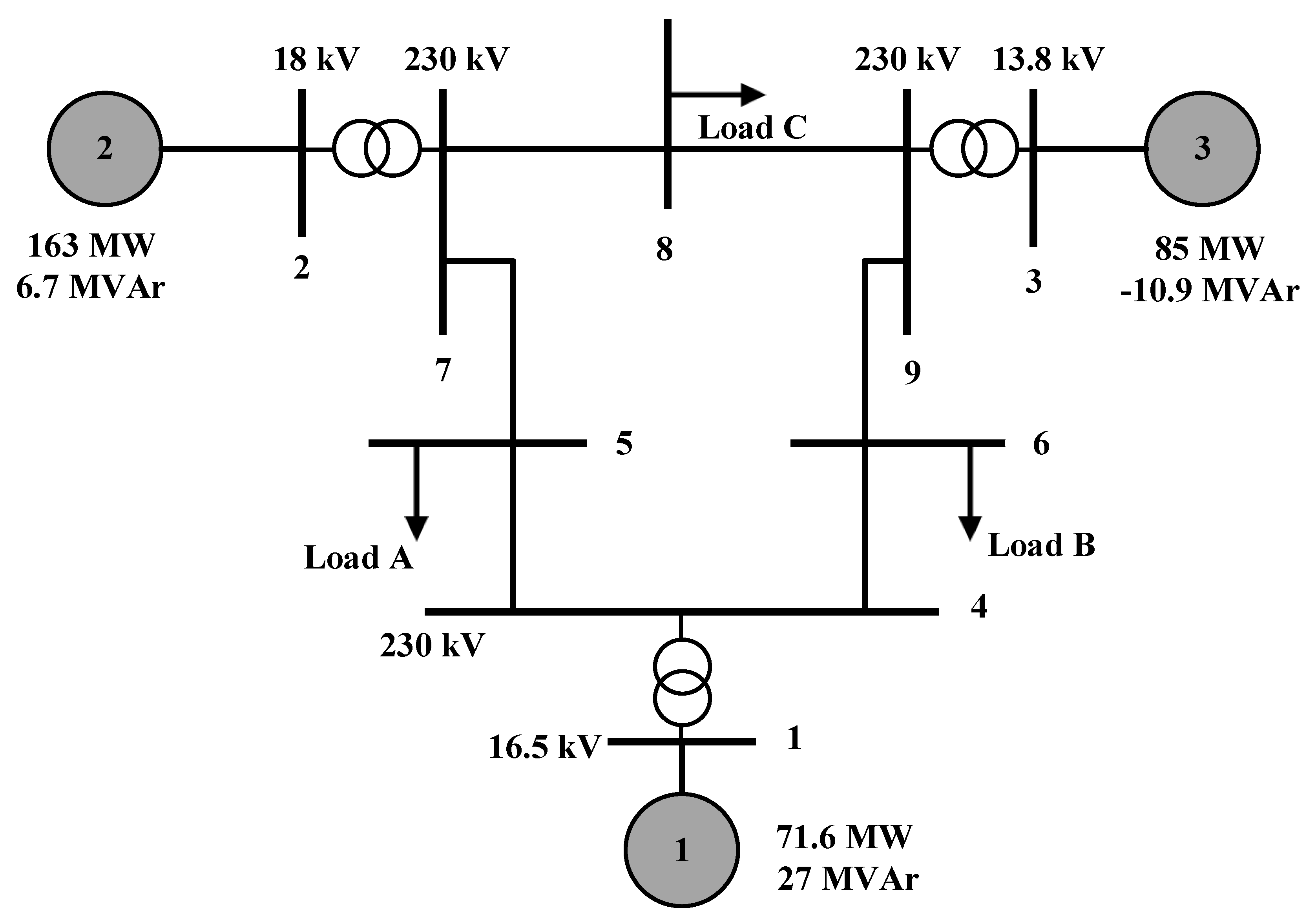
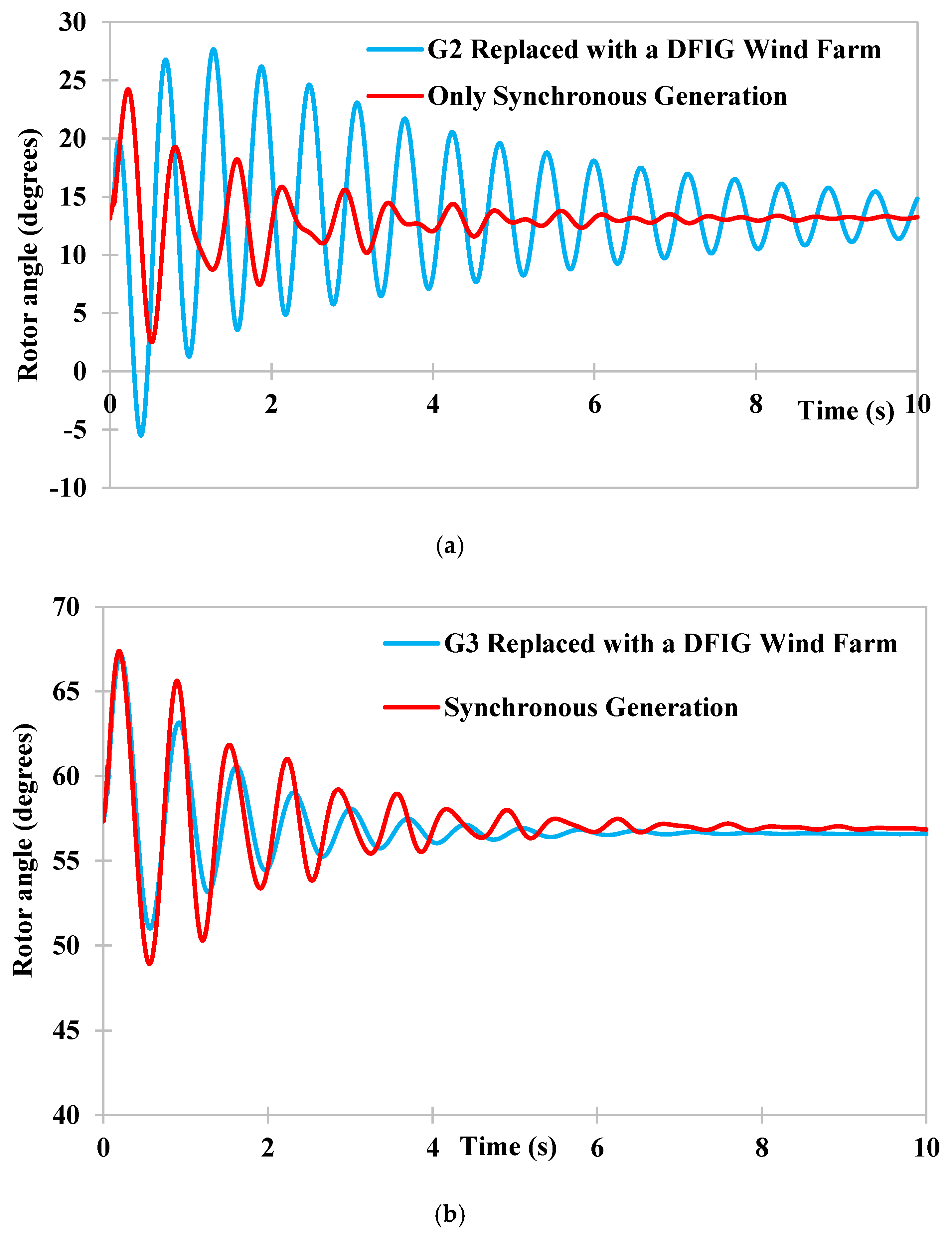
To illustrate the impact on transient and small-signal stability with wind generation the 9-bus system (see Appendix A for the 9-bus system model) was used in this case study [38]. In first scenario, the generator, G2, was replaced with a DFIG wind farm with the same MVA capacity and is generating the same active and reactive power. In the second scenario, G2 was replaced with a DFIG wind farm with same MVA capacity and is generating the same active and reactive power. The rotor angle variation following a 50-ms three-phase short-circuit fault in line 5–7 is shown in Figure 3.
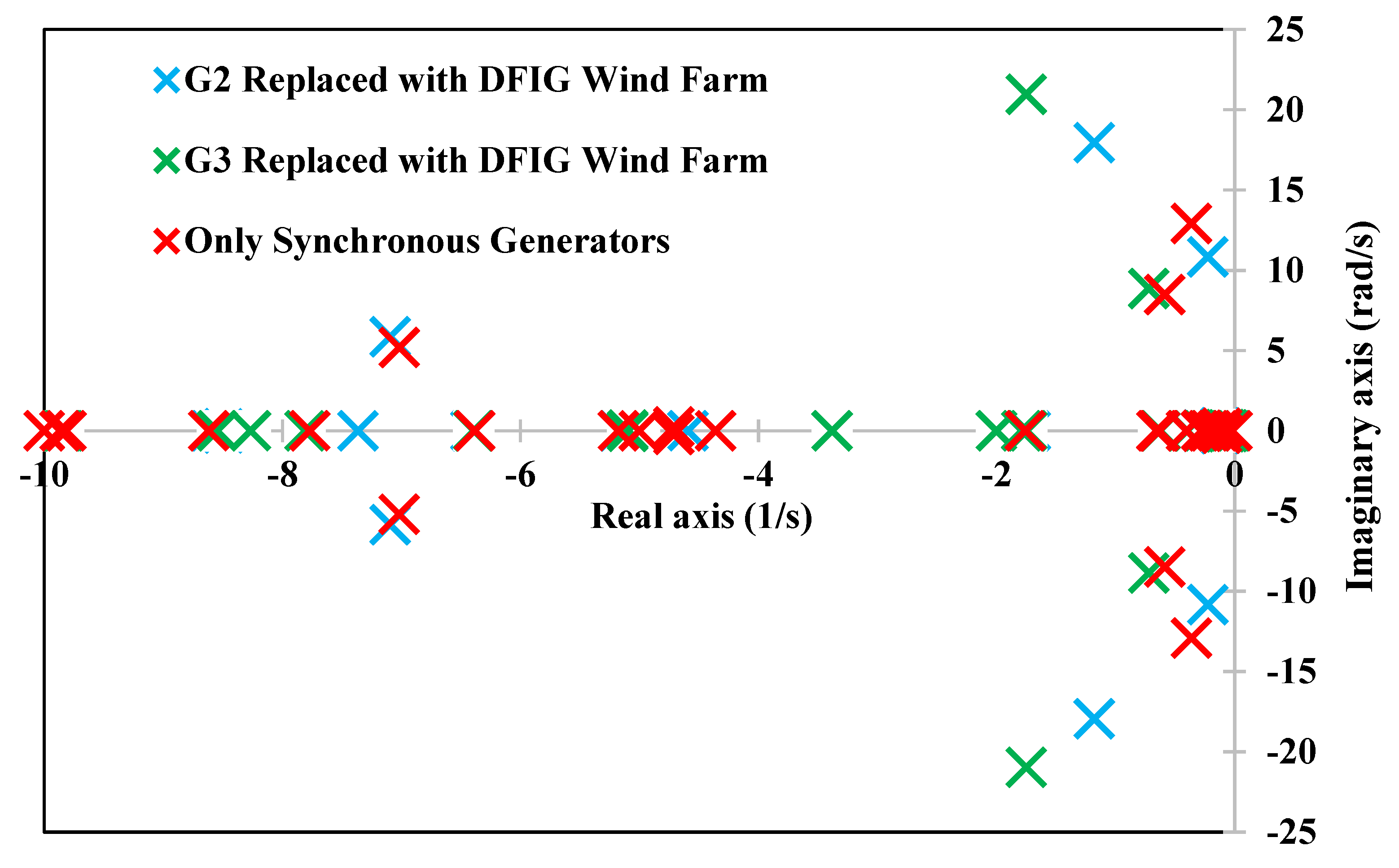
According to Figure 3, when the synchronous generator G2 is replaced by an equivalent capacity DFIG wind farm, the synchronous generator G3 indicates large rotor-angle oscillations (with an oscillation frequency of 1.85 Hz) compared with synchronous generator-only scenario. However, when the generator G3 is replaced with an equivalent DFIG wind farm, the G2 rotor angle oscillations dampened rapidly compared to the synchronous generator-only scenario. A similar observation can be seen from the Figure 4, which illustrates the system eigenvalues for the two wind integration scenarios and synchronous generator scenario. According to the eigenvalue plot in Figure 4, when the generator G2 is replaced by the DFIG wind generation, oscillatory modes move closer to the imaginary axis, and when the G3 is replaced by the DFIG wind generation, oscillatory modes move away from the imaginary axis indicating an improved oscillatory stability. Therefore, when the synchronous generators are replaced with PEC-interfaced DFIG wind farms, it had beneficial and adverse effects on rotor angle stability and this conclusion is consistent with the conclusions presented in [22].

4. Impact on Frequency Stability with PEC-Interfaced Renewables

Frequency stability is closely associated with the rotor angle stability, since synchronous generator rotor speed is synchronized with the system frequency. Therefore, any change in system frequency is reflected on synchronous generator rotor speed. Frequency stability is associated with the instantaneous balance of active power demand and generation in the power grid [39] and is maintained through primary, secondary, and tertiary control responses [40]. Figure 5 shows the different recovery stages of system frequency following generation-demand imbalance in the network.
The primary response is composed of an initial inherent inertial (natural) response [41,42], followed by a primary control action. As traditional synchronous generators are directly coupled (electromechanically) to the grid, upon a change in frequency, they are inherently able to deliver or absorb kinetic energy to help stabilize the system frequency (via inertial or natural response). The natural response/inertial response from a directly grid connected generator can be approximated as;
Δ P g e n = 2 E g e n f 0 · d f d t
where Egen is the stored energy capacity of the generator in MWs, f0 is the system nominal frequency in Hz, and df/dt represents the rate-of-change-of-frequency (RoCoF) in Hz/s during the disturbance. All the synchronous machines provide this response during a disturbance and will assist the frequency for a 0.5–1 s period. The primary control action, which follows the inertial response, involves the linear (proportional) adjustment of the synchronous machine’s active power delivery given a change in frequency, thereby helping to stabilize the system [43,44]. The primary response of a synchronous generator is given by;
Δ P m , i = 1 R i Δ f
where Δ P m , i is the change in turbine power output of the i th generating unit in MW, 1 R i is the droop regulation constant, and Δ f is the frequency deviation from nominal frequency in Hz. Given a set of generators G , then the total change in power generation within a system is the sum of the changes of each generator as given by (5).
Δ P t o t = i G Δ P m , i
However, the primary response does not return the frequency to its nominal value owing to the use of proportional control. Secondary frequency control, also known as the automatic generation control (AGC), follows the primary response to return the frequency to its nominal value via the proportional-integral (PI) control scheme. The time-error correction of frequency is achieved through alteration of the power reference settings of the synchronous generators to account for the change in total power demand. For a multi-area power system with a set of J areas, AGC is used to control the tie-line power flows and frequency, such that
P t o t ( P L P t i e ) = 0
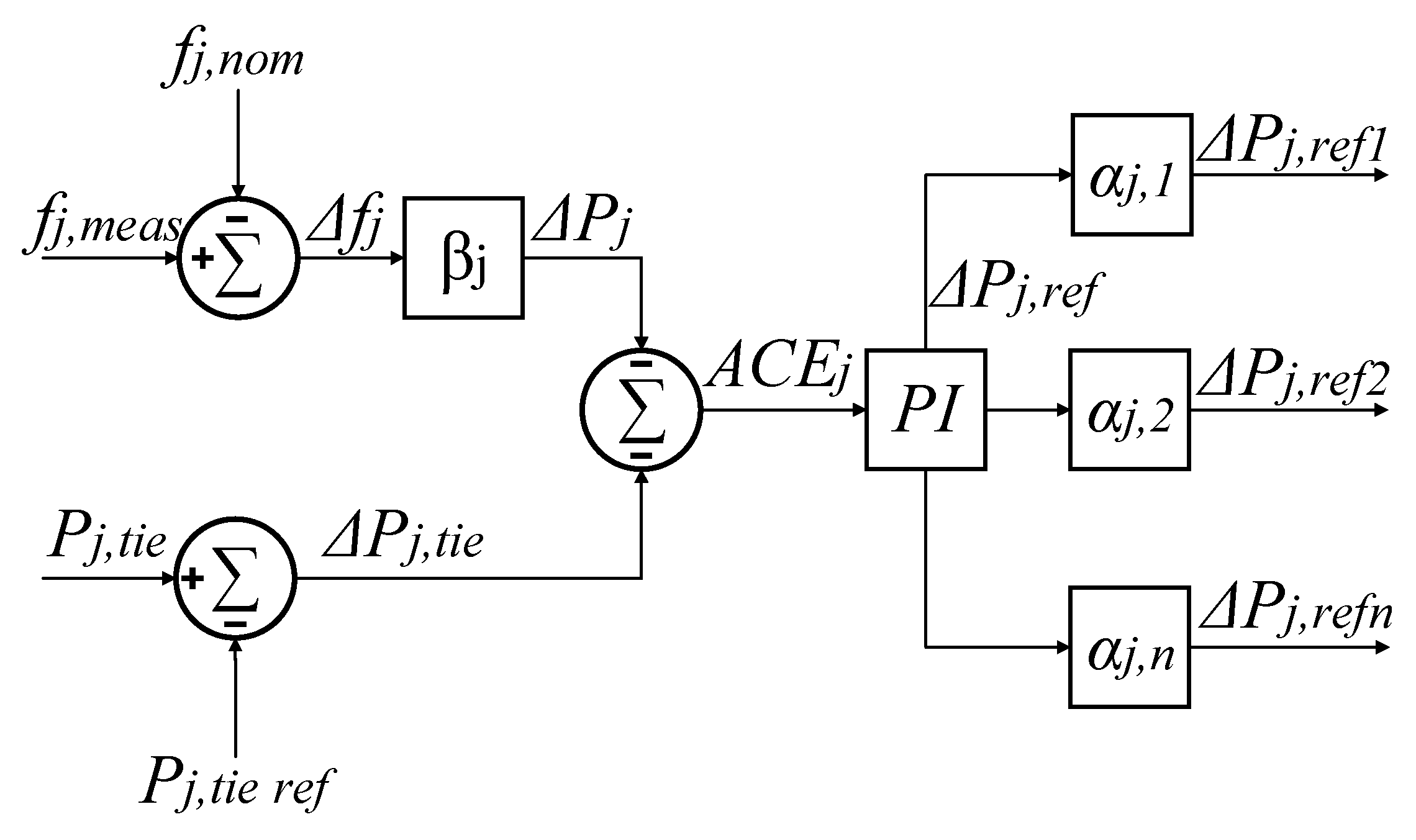
where P t o t is the total power generation in MW, P L is the total demand of the load in MW, and P t i e is the tie-line power flow(s) in MW. Figure 6 illustrates a traditional AGC scheme.
The tie-line power flow P j , t i e and local area frequency f j , m e a s is measured and compared with their respective setpoints or nominal values ( P j , t i e and f j , m e a s , respectively) for each area j J . The frequency error signal Δ f j is multiplied by the area frequency bias β j , which has units MW/Hz, to produce Δ P j , which represents the amount of active power generation (in MW) required to compensate for the frequency deviation resulting from the active power imbalance within the area. The area control error (ACE), A C E j is determined by adding the net tie-line power interchange, Δ P j . t i e , and the change in generation Δ P j namely;
A C E j = Δ P j , t i e β j Δ f j
The ACE is the amount of change required in total area power generation to maintain the tie-line power flows and frequency at their scheduled values. To provide time-error correction of frequency a PI controller is used. The control output signal, Δ P j . r e f is multiplied by the participation factor α k of each generating unit, where α k = { α k | k [ 1 , n ] } , which is typically based on the rating of each respective machine. On the other hand, tertiary control responses refer to manual variations in unit commitment [45].
Modern power systems contain increasing amounts of wind and solar-PV generation, which typically use PECs as an interface to the grid [46,47]. In contrast to traditional synchronous generators, the power electronic interface effectively decouples renewable energy generators from the power network dynamics and reduces the inertia of the system. Reduced system inertia leads to faster frequency dynamics [48], which challenges the control of system frequency. The displacement of conventional synchronous generation and introduction of the PEC-interfaced generation with different dynamics augments the power system’s modes of oscillation [49]. Additionally, renewable energy generation is also stochastic, which introduces uncertainty and further challenges the system’s frequency stability [50]. However, a large body of work is currently underway to provide solutions to such challenges, which are covered below in further detail for both wind and solar-PV systems.
The conventional fixed-speed wind generators typically employ squirrel-cage induction generators and have a strong coupling between the rotor speed and the system frequency, allowing them to provide the inertial response [42]. Modern wind generators are typically variable-speed, such as DFIGs and permanent magnet synchronous generators (PMSGs), which employ PEC-interface for grid integration. Such generators are connected to the grid via power electronic interfaces, which decouples them from the power system network dynamics [51]. For example, DFIGs operate to apply a restraining torque to the rotor according to a predetermined curve, resulting in a control scheme, which is not based on power system frequency, thus providing negligible amounts of inertia [52]. However, additional control loops can be implemented to allow the kinetic energy stored in the turbine blades to be released into the network [53,54], which has formed a large body of recent research. This synthetic response obtained from the PEC-interfaced sources is commonly known by several names, such as the synthetic inertia, the virtual inertia, the emulated inertia, and the fast frequency response (FFR). There are three main methods reported in the literature to emulate inertial response from the PEC-interfaced RES; (1) based on frequency error (Δf) and also known as the droop control, (2) based on the derivative of the frequency (df/dt) and also known as the inertia control, (3) based on a fixed trajectory when the frequency exceeds a pre-defined threshold [55].
Inertia control involves with imitating the behavior of the short-term rotational energy storage of wind generators by using the derivative of the system frequency (i.e., df/dt), hence the electro-magnetic torque reference given by [56];
T e , r e f = K O P T ω r 2 H v ( s ) ω m
where T e , r e f is the desired electromagnetic torque, K O P T is the optimal power coefficient related to the blade angle, ω r is the DFIG rotor angular speed in rad/s, H v ( s ) is the virtual inertia, and ω m is the angular frequency of the grid in rad/s. In this case, the additional power supplied by the wind generator is proportional to the derivative of the system frequency (i.e., df/dt). Such a control scheme is termed inertia control. Single-loop control schemes based on the RoCoF, and two-loop control schemes utilizing RoCoF and the frequency deviation, are used to provide inertia emulation [57].
Recent work has proposed an optimized power point tracking controller for variable-speed turbines, which shifts the operating point of the wind turbine from the maximum power point tracking to virtual inertia control, allowing for the release of kinetic energy and provision of dynamic frequency support to the grid [58]. Additionally, multi-objective virtual inertia control schemes have been shown to improve the transient stability of interconnected power systems [59], by allowing wind generators to share the accelerating energy with synchronous generators while providing decelerating energy to reduce the rotor’s angle variation during the first swing period.
In droop control the torque setpoint is altered based on the frequency deviation ((i.e., Δf) from the nominal value in a similar manner to synchronous generators [60,61]. When the droop control (i.e., Δf strategy) is employed the emulated frequency response (ΔPwind), is given by;
Δ P w i n d = lim [ Δ f · ( s K d ( 1 + s T c ) ( 1 + s T d ) ) , p i _ min , p i _ max ]
where, Kd is the controller gain, Tc and Td are lead and lag time constants in s, and Pi_min and Pi_max are the limits of the controller. Furthermore, wind turbines can also be deloaded to shift the operating point of the generator away from its maximum power point to provide active power reserve [54,62]. Upon a decline in frequency, the generator can provide active power to help stabilize the frequency.
The wind is inherently a stochastic resource, and consequently, this uncertainty can challenge power system stability owing to fluctuations in the active power output of wind farms. Energy storage has been proposed to support wind energy to reduce the effects associated with the wind speed [63]. The combined control of DFIG-based wind turbines and battery energy storage systems (BESSs) has been proposed for microgrids [64]. In order to improve the system frequency regulation, super-capacitors/ultra-capacitors are also proposed for PEC-interfaced wind generators [65,66]. Additionally, a control scheme comprising inertia emulation and primary frequency response capability has been shown to improve the grid’s frequency response by lowering the RoCoF and ameliorating the frequency nadir [67]. Multi-agent control has also been shown to be useful for optimal load frequency control consisting of both synchronous generators and wind turbines [68]. In the future, as more significant amounts of wind energy are connected to systems in a decentralized manner, such control schemes will become increasingly necessary.
As wind and solar stochastic resources introduce uncertainty and again challenges system frequency stability owing to fluctuations in active power output (and thus system frequency). Coordinated control has been shown to effectively smooth such fluctuations in hybrid isolated systems [69]. Energy storage systems (ESSs) can also be used to support solar PV systems [70]. A unified control and power management scheme for hybrid microgrids containing PV and energy storage has been utilized for grid-connected and islanded modes of operation to regulate frequency effectively [71]. Deloading of solar PV plants, in a similar way to wind turbines, allows for the provision of FFR owing to the active power reserve [72]. Figure 7 summarizes the main methods discussed for providing frequency response from wind and solar-PV systems.

A Case Study—Frequency Stability with DFIG Wind Generation

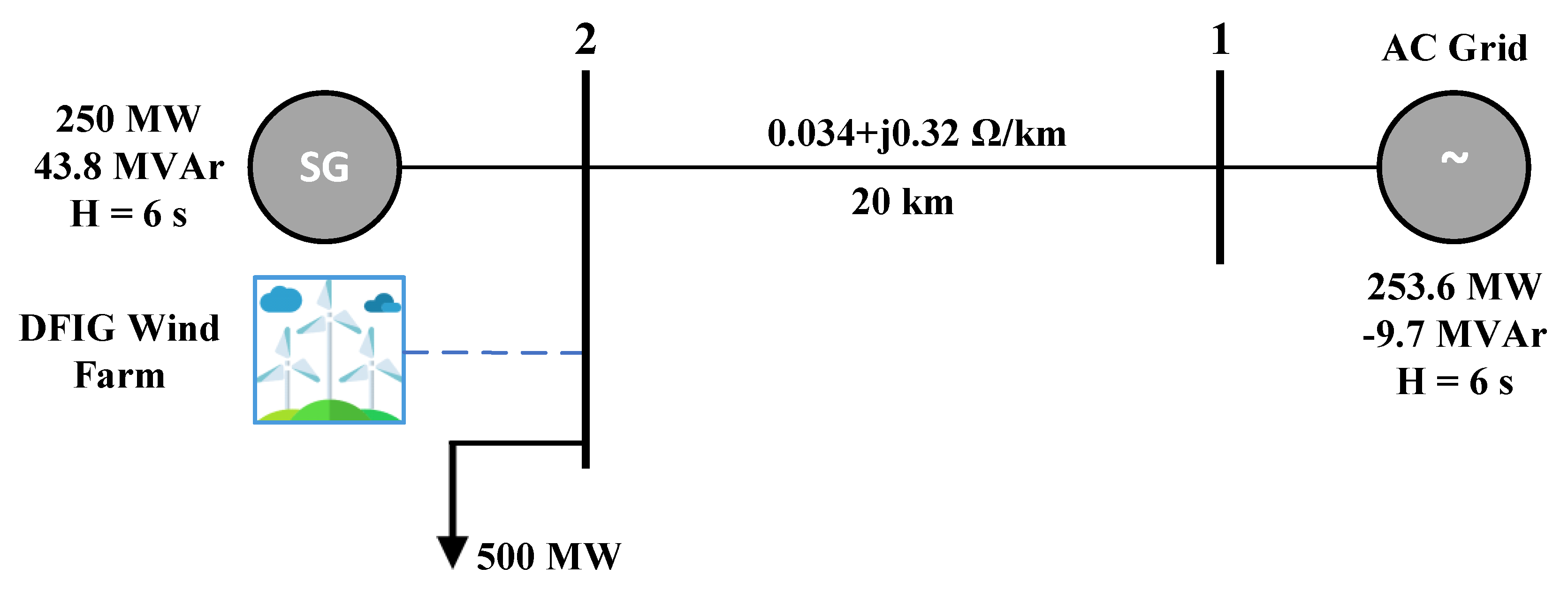
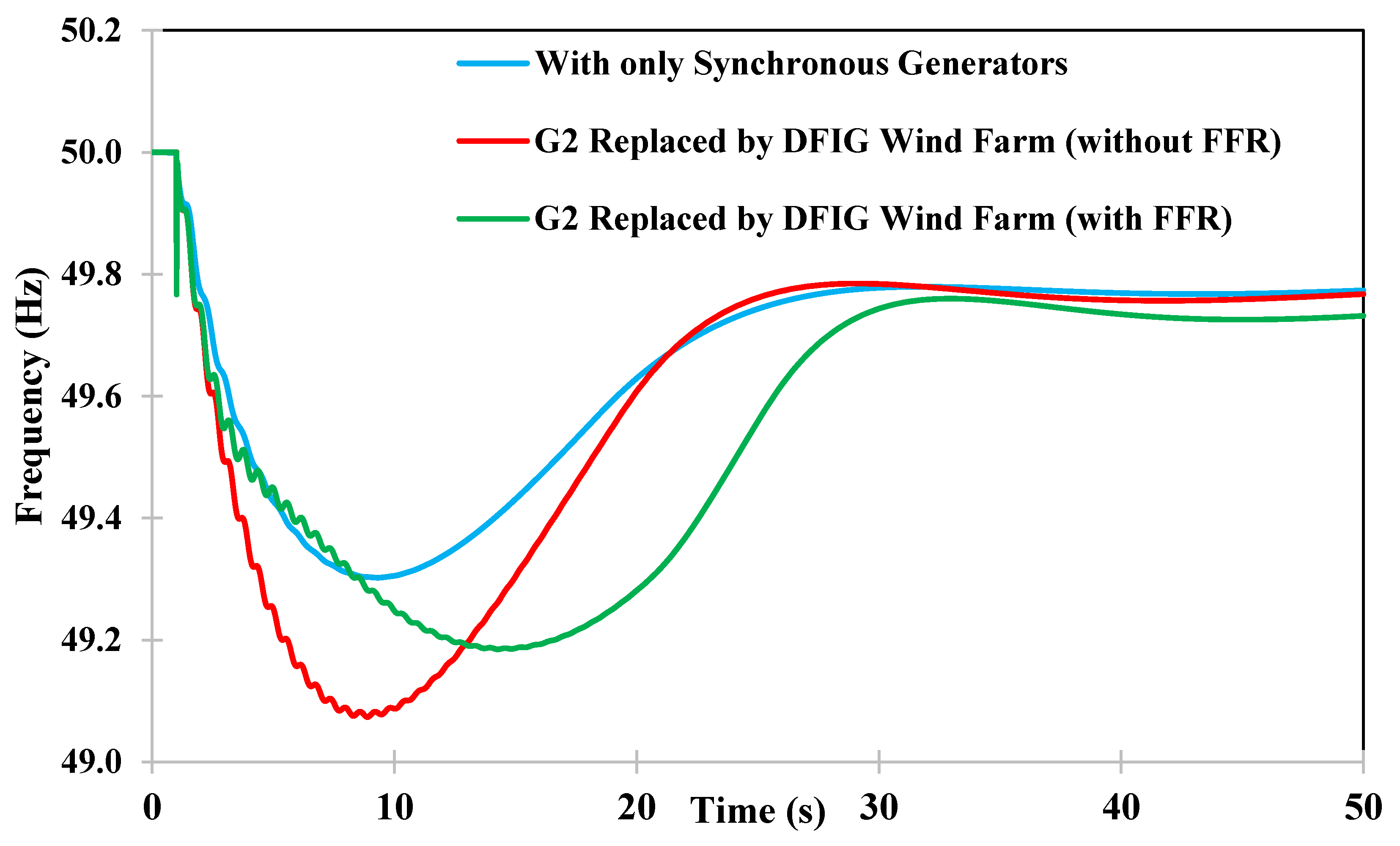
In order to illustrate the influence of the PEC-interfaced generation on the frequency stability, a 2-bus system (see Appendix B for network model) was used in this case study. Three scenarios are simulated in this study; (1) Synchronous generation, (2) G2 is replaced by a DFIG wind farm without inertial response, (3) G2 is replaced by a DFIG wind farm with inertial response. Inertial response is based on the frequency error method presented in [73]. Figure 8 illustrates the system frequency response following a 10% load addition (31.5 MW load at bus 8, t = 1 s) to the network.
According to Figure 8 when the synchronous generator, G2 is replaced by a similar capacity DFIG wind farm, the frequency nadir has reached 49.07 Hz, while it was 49.30 Hz when the 9-bus system has only synchronous generation. In addition, RoCoF has also increased when the DFIG wind farm (without FFR) is connected to the grid. When the DFIG wind farm is equipped with the FFR capability frequency nadir has improved to 49.18 Hz and RoCoF is also similar to the synchronous generator scenario. However, it takes much longer for frequency to recover to the quasi steady-state frequency due to the energy recovery from the DFIG wind farm. In some cases, energy recovery could result in a second frequency nadir, hence the energy recovery stage should be properly coordinated within the wind farm.

5. Impact on Voltage Stability with PEC-Interfaced Renewables

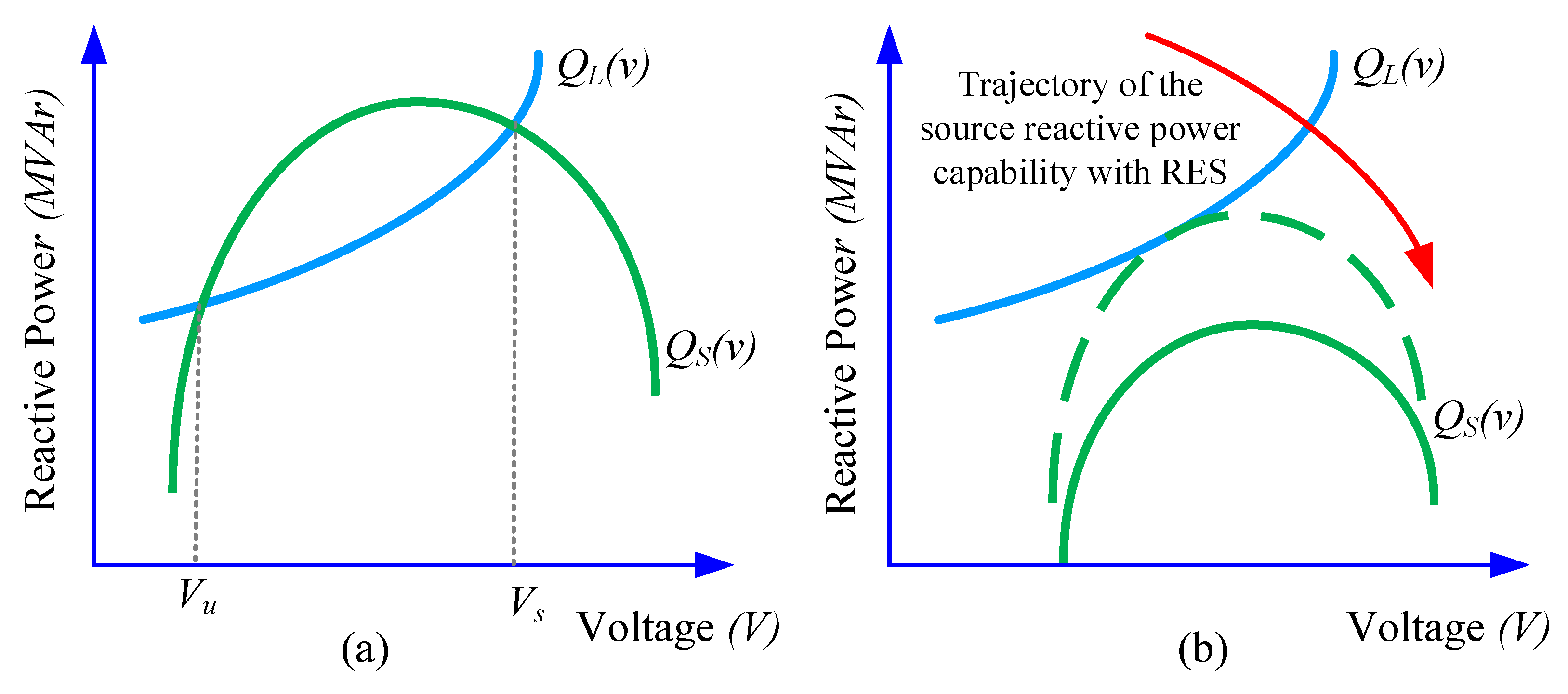
Voltage stability is defined as the ability of power network busbars to recover and maintain steady-state acceptable voltage levels after being subjected to a fault or multiple faults in the network [18]. A number of early voltage stability studies conducted on actual power networks highlighted the voltage stability benefits of PEC-interfaced wind generation technologies over conventional wind generation technologies (fixed-speed wind generators) [74]. The voltage stability issues originating from the PEC-interfaced RES could occur mainly due to the shortage in the reactive power reserve and low short-circuit capacity in the network due to replacement of conventional synchronous generators. The source reactive power, Qs(v) when it supplies a load connected via a transmission line having reactance, XL, can be determined as follows;
Q s ( v ) = [ E V X L ] 2 [ P L ( v ) ] 2 V 2 X L
where, E is the source voltage, V is the load voltage, and PL(v) is the load active power demand. According to the voltage stability theory, the source reactive power should be able to fulfill the system reactive power demand (i.e., load reactive power and system reactive power losses), hence if the system is stable then the source reactive power curve and the system reactive power curves must intersect with each other as shown in Figure 9a. However, only one solution is feasible under these circumstances, which corresponds to voltage, VS in Figure 9a. However, if the source reactive power, Qs(v), is not sufficient to meet the load reactive power demand, QL(v), then there will not be an intersecting point, hence voltage would collapse. This condition is illustrated in Figure 9b.
The voltage stability, can be broadly classified as steady-state and dynamic voltage stability. Over the past two decades many research studies have been conducted on the impact of PEC interfaced renewables on voltage stability, and they can be broadly classified into two types; (1) Steady-state voltage stability, (2) Dynamic voltage stability [18]. The dynamic voltage stability can be broadly divided into two types; (1) Short-term voltage stability (STVS) and (2) Long-term voltage stability (LTVS). In STVS studies, ability of busbars to recover back to steady acceptable voltage level within short durations are considered (within 5–10 s timeframe). The LTVS is typically evaluated between 200–300 s timeframe. Therefore, the impact on steady-state and dynamic voltage stability due to PEC interfaced renewable generation are discussed separately in the following sub-sections.

5.1. Steady-State Voltage Stability

The steady-state voltage stability is defined as the ability of the power network busbars to maintain steady-state voltage levels during small and gradual changes in the network. Usually, steady-state voltage stability is assessed via voltage sensitivity with active and reactive power. P-V curves, Q-V curves, and modal analysis are used to assess voltage stability. In [75], the authors analyzed the steady-state voltage stability with wind generation using P-V curves. The authors used a time-series load-flow analysis technique to analyze various wind penetration scenarios and analyzed the voltage stability margin (critical voltage point) obtained through the P-V curves and highlighted the importance of voltage control strategies implemented in wind farms [76]. The authors in [76] argued that reactive power capability of PEC-interfaced generation sources must be properly coordinated to ensure voltage stability of the network, otherwise the system could operate closer to the voltage stability margin if the PEC-interfaced wind generators operate at maximum reactive power. Another voltage stability study conducted using PV curves concluded that voltage stability and system loadability could be improved with the increasing DFIG penetration [77]. In particular, authors have highlighted the importance of utilizing the voltage control strategy in wind farms in contrast to power factor control strategy.
Reactive power reserve is rapidly depleting in power networks due to displacement of synchronous generators. In addition, as the PEC-interfaced generation sources are integrated to remote locations in the power network, system requires additional reactive power reserves to maintain voltage levels within stipulated standards. Therefore, the VQ stability margin is more imperative with PEC interfaced renewable power generation in power grids. In [78], the VQ stability margin was used to assess the steady-state voltage stability with wind (i.e., DFIG wind farms) and solar-PV generation. This study emphasized the importance of the reactive power control strategy and reactive power capability of the PEC-interfaced source for maintaining voltage stability of the network [78]. Due to the variability of renewable energy resources, power generation from wind and solar-PV generators likely to change, hence system stability could be viewed from a probabilistic perspective rather than a deterministic viewpoint. Therefore, the authors in [79] presented a two-stage stochastic voltage stability assessment process for renewable rich power grids, considering the uncertainties associated with wind power injections to the grid.
Steady-state voltage stability outcomes have been used in various planning studies. For example, in [80], the authors used steady-state voltage stability results obtained via QV modal analysis to integrate wind generation to a power network. Study concluded that if voltage-controlled PEC-interfaced wind generators (e.g., DFIG and PMSG) are integrated to weak nodes in the network, they could improve the VQ stability margin significantly compared to integrating them at strong nodes in the network. The work presented in [81] proved that optimization of voltage control resources at distribution network could achieve improved voltage stability in the transmission network. In addition, a number of studies have reported the use of various additional reactive power devices, such as STATCOMs and static VAr compensators (SVCs) to preserve voltage stability of the network [82].

5.2. Dynamic Voltage Stability

Dynamic voltage stability is analyzed under-large network disturbances, and it is also analyzed in two time-scales; (1) STVS time-scale, and LTVS time-scale. The STVS phenomenon is driven by dynamic loads such as induction motors while the LTVS phenomenon is driven by on-load tap-changing transformers and over-excitation limiters in synchronous machines. The research studies conducted on PEC-interfaced renewables have highlighted the impact on both phenomena [83].
The early studies conducted on PEC-interfaced variable-speed wind generators concluded that PEC-interfaced wind generators could avoid STVS issues and the possibility of voltage collapse in the network with the improved control functionalities offered by these generators [84]. Another study conducted with PEC-interfaced generation concluded that dynamic reactive power injection by PEC-interfaced wind turbines based on E.ON grid code provide better voltage support than power factor control mode [85]. A large disturbance voltage stability study presented in [86] concluded that when both the conventional synchronous and the PEC-interfaced generation resources are dominant in a region that could lead to adverse stability impact due to non-complementary characteristics of both technologies.
The LTVS study conducted with a DFIG-based wind power generation has concluded that reactive power capability of the GSC of the DFIG assist to improve LTVS of the power system [87]. Contrary to this, the STVS and LTVS study presented in [83] with DFIG-based wind generation concluded that DFIG wind generation could lead to reduced STVS and LTVS, since DFIGs do not have overloading capability similar to conventional synchronous generators.
The LTVS study presented in [88] analyzed a number of factors influencing the LTVS of the power system. These factors include, wind generator loading levels, proximity to load centers, and wind integration options. The study concluded that when the synchronous generators sited in close proximity to load centers are replaced by wind farms, they could give rise to a detrimental impact on LTVS. A comprehensive LTVS study presented in [89] analyzed the various factors influencing the LTVS in the context of large-scale solar-PV generation. These factors include inverter rating, current limiting strategies, reactive power gain, solar-irradiance, and temperature. The study showed that large-scale solar-PV generation has both beneficial and adverse impacts on stressed power networks. However, the enhanced reactive power controller proposed in the study could alleviate those adverse impacts. Therefore, additional dynamic reactive power compensation devices may be required to preserve the LTVS of the network.

5.3. Real-Time Voltage Stability Analysis

Various real-time voltage stability analysis methods have emerged in the past decade to monitor real-time voltage stability in wind-rich power grids [90]. Typically, PMU data channels are being used for real-time voltage stability monitoring and analysis [91,92]. Thevenin equivalent and Lyapunov exponent are the most commonly used methods in real-time voltage stability analysis [93]. In [90]. the authors used real-time PMU measurements to assess the voltage stability, and have concluded that wind farms located at remote locations could not provide the reactive power support due to the high line impedance between the wind farm and the substation.

5.4. Case Study—Voltage Stability with DFIG Wind Generation

This sub-section aims to demonstrate the impact of PEC-interfaced wind generation on voltage stability using the same 9-bus system used in previous case studies. The Q-V curve-based method is used in this case study to assess the voltage stability with three scenarios; (1) Synchronous generation only, (2) G2 is replaced by a DFIG wind farm (voltage control mode), G2 is replaced by a DFIG wind farm (power factor control mode). Figure 10 illustrates the Q-V curves for bus-8 under three scenarios for the network.
According to Figure 10, when the G2 is replaced with a similar capacity DFIG wind farm operating at power factor control mode, the voltage instability point (e.g., dq/dv = 0) reached 0.62 pu voltage with reactive power of −157 MVAr, indicating a deterioration in the static voltage stability margin. However, when the DFIG wind farm is operating at voltage control mode, the voltage instability point reached 0.54 pu with reactive power of −384 MVAr, indicating an improvement in static voltage stability margin. Therefore, it confirms the fact that the operating mode of the wind farm has some influence on the voltage stability of the power grid.

6. Sub-Synchronous Interactions and Oscillatory Stability

Sub-synchronous interactions (SSI) and oscillatory stability are another stability concern for renewable rich power grids and these oscillations are typically monitored as either power or voltage oscillations. In recent years such oscillatory stability issues were reported in Texas, USA and China, and such incidents are likely to occur in the future under high penetration levels of PEC-interfaced renewables. The comprehensive classification presented in [94] classified the power system oscillatory stability into two (2) main categories; (1) Low-frequency oscillations, (2) Sub/Super-synchronous interactions/Resonance.
Low frequency oscillations are occurring in the frequency range of 0.1 to 3 Hz, and these oscillations can be divided into three categories; (1) Local machine system oscillations, (2) Interplant oscillations, and (3) Inter-area oscillations [94]. Usually, these issues are investigated using small-signal stability domain using eigenvalue analysis. Although some studies argued that the PEC-interfaced RES lead to reduced damping due to the decoupled nature of the mechanical dynamics of the PEC-interfaced wind energy conversion systems (WECSs) with the electrical dynamics due to the PEC interface [49,95], majority of the studies have augmented the PEC controller to provide damping for oscillations [96]. For example, in [97,98], authors have proposed a control scheme for the DFIG rotor-side converter (RSC) to damp the inter-area oscillations.
Sub-synchronous interactions originating from the PEC-interfaced wind farms connected to series compensated transmission lines received an enormous attention during the past decade due to increased integration of PEC-interfaced wind farms using long-distance transmission corridors [99,100]. Sub-synchronous interactions/oscillations can be basically classified into three-types; (1) Sub-synchronous resonance (SSR), (2) Sub-synchronous torsional interaction, and (3) Sub-synchronous control interaction (SSCI). Typically, eigenvalue analysis and impedance-based frequency scan approaches are being used for SSCI studies. The SSI phenomena can be exemplified using Figure 11.
The resonance frequency (fr) associated with the wind farm connected to series compensated transmission line can be determined as;
f r = f 0 X c X W + X R + X T
where, f0, Xc, XW, XR, and XT denote nominal system frequency in Hz, reactance of the series compensated capacitor in Ω, reactance at the wind farm in Ω, transformer reactance in Ω, and transmission line reactance in Ω respectively. In conventional SSR phenomenon, this resonance frequency coincides with the natural frequency of the drive-train system of the generator, and that can create undamped oscillations between the network and the drive-train system. This conventional phenomenon does not apply exactly for PEC-interfaced RES due to the PEC interface between the mechanical system and the electrical network. However, this phenomenon could occur under multiple frequencies depending on the operating condition of the PEC-interfaced RES and could aggravate due to the PEC control scheme and this is typically classified as SSCI [101].
The SSCI is the phenomenon mostly relevant for PEC-interfaced RES. SSCI issue associated with the PEC-interfaced generation source was first discovered from a DFIG wind farm connected to the series compensated transmission line in Texas, USA [100]. In this event, the impedance between the DFIG and series compensated line became zero negative for the sub-synchronous oscillation, and subsequently led to the resonance phenomenon. Since then a number of studies have been done to characterize and mitigate the SSCI in PEC-interfaced generation systems [86,87].
In [102], it was argued that SSCI has occurred not due to negative resistance but due to the resonance between the generator and the network, and also revealed that low damped oscillatory mode has a possibility of creating a SSCI between the network and the DFIG. Authors have further mentioned that the controller gains could be tuned to damp this oscillatory mode [102]. A study conducted in [103] showed the influence of the wind speed, RSC current controller gains, and compensation level on SSR. SSR characterization study presented in [104] further confirmed the electrical resonance phenomenon between parasitic elements in the network and DFIG converter controller influence on SSR. Moreover, another study also showed the fact that low wind speed and the number of online DFIG wind generators adversely influence the SSR phenomenon. In [101], the authors have proposed supplementary damping control schemes for both the RSC and the GSC to damp the SSIs.

7. Influence of RES Fault Ride-Through on Power System Stability

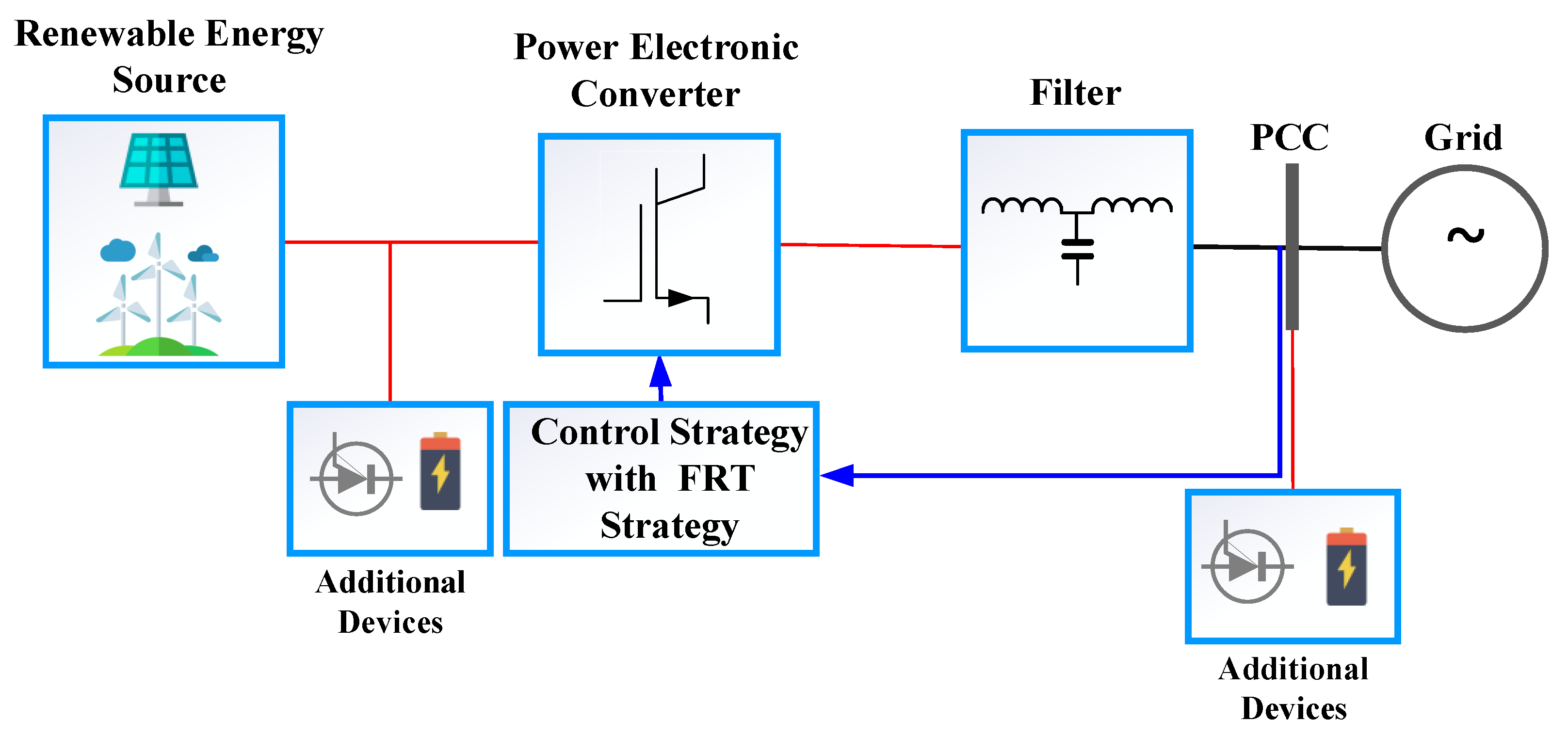
The stability of the power grid under high penetration levels of PEC-interfaced generation sources is also influenced by the FRT capability/strategy of the PEC-interfaced sources, which determines the RES’s ability to remain connected during network fault events and support the network to recover once the fault is cleared [105].
Presence of PEC-interfaced RES near to a load center allows the provision of ancillary services, such as the supply of reactive power to improve voltage support during voltage sags originated from faults in the network [106]. These services could be supplied by the FRT capability integrated with PEC-interfaced RES. Also, it would enable PEC-interfaced RES to withstand voltage dips due to grid faults. The FRT capability is mainly built into the PEC controller of the PEC-interfaced RES as shown in Figure 12. Moreover, additional devices are also proposed (e.g., braking chopper (BC) [107], fault-current limiter (FCL) [108]) for individual RES and RES clusters (e.g., wind and solar-PV farms) at their collector point to assist PEC-interfaced renewables to ride-through faults as shown in Figure 12.
The grid-connected RES may act as a STATCOM during the fault, providing reactive power to improve the voltage stability of the network [30,106]. Control system studies for STATCOM operation are widely carried out in the published literature, such as DC-link control in a WECS during a fault [109], grid connectivity studies for WECSs and solar-PV systems working as STATCOMs in day and night times [110], and a PV-STATCOM combination with power oscillation damping and partial PV-STATCOM mode during the recovery stage after a fault while increasing the power transfer capacity of the line and the stability of the network [111]. Presence of PEC-interfaced RES can improve the stability of the network, if the installed PEC-interfaced RES has enhanced FRT capabilities. The review of FRT capability of WECSs and solar-PV are presented in the next subsections.

7.1. FRT Strategies of PEC-Interfaced WECSs

The use of different types of PEC-interfaced WECS could affect the stability of the entire power grid. Therefore, it is imperative that these WECSs are fault tolerant, hence should employ different FRT strategies [105], which can assist with the recovery of the power system during a fault or at least to ride-through the fault while keeping the WECS connected. Many studies have been carried out to characterize the WECS behavior during power system faults, and it is determined that PEC-interfaced RES are vulnerable to disturbances, faults and low grid voltages [112].
Different FRT approaches proposed for PEC-interfaced WECS can be categorized as passive methods and active methods [105]. In passive methods, FRT schemes only ensure connectivity of the PEC-interfaced source during the disturbance, while in active methods, enhanced grid support services are provided by the PEC-interfaced source. One of the technological advances that is currently taking place is the use of superconducting fault current limiters (SFCLs). For example, SFCL was proposed for DFIG based WECSs in [113,114], cooperative strategies between a SFCL and superconducting magnetic energy storage (SMES) system were proposed in [115]. The bridge-type FCL was proposed in [116] for fixed-speed wind generator. Besides, FRT strategies are also proposed for PMSGs, either using resistive-type SFCL [108] or modified SFCL [117]. These hardware solutions provide improved response against voltage dips/sags during faults and also act as a protection mechanism for the DC-link when a voltage dip occurs in the network.
On the other hand, in addition to hardware solutions, there are also software solutions proposed in the literature depending on the type of machine used for the WECS, such as control strategies for both converters (RSC and GSC) in DFIG-based wind turbines [118], where the RSC can convert the power imbalance into kinetic energy of the wind turbine and the GSC introduces a compensation term in order to smooth the DC-link voltage fluctuations. Also, a hybrid controller that uses an ESS and BC for FRT of PMSG was also proposed in [109]. Control strategies that could influence the mechanical power of the machine are proposed for squirrel-cage induction generator-based fixed-speed wind generator [119]. Also, reference [120] presents a study of three types of controllers for FSIG, the first type proposes a SFCL, the second type modifies the conventional pitch angle controller, and the third type performs an adaptation of the wind turbine gearbox ratio.
As it can be seen, there are several solutions to tackle the FRT issue in WECSs, and they could impact the design and operation of wind turbines to provide this FRT capability. In [121], researchers investigated the impact of FRT on wind turbine design and operation with different generators, such as DFIG, PMSG, squirrel-cage induction generator, and wound field synchronous generator. As mentioned previously, wind generators should be capable to ride-through the fault without disconnecting from the grid while providing reactive power during the fault and also should assist to recover the power network [122]. The DC-link should be controlled by controlling the active power, while the GSC injects reactive current to the grid to assist the grid voltage recovery in order to accelerate the recovery process [109]. This could be achieved with the use of external devices and modified controller-based methods [123], therefore the cost has become the main factor in selecting the most suitable method.
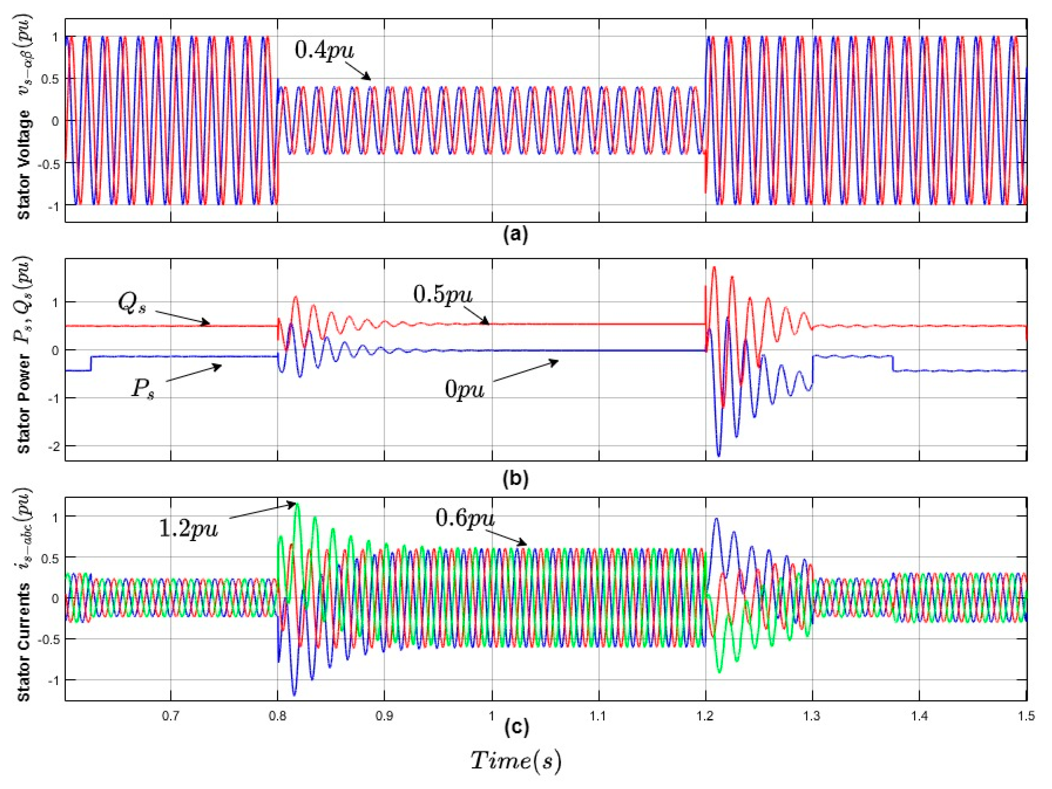
An example of the DFIG wind generator FRT capability is shown in Figure 13, where the DFIG wind generator experiences a voltage dip and its predictive control strategy [124] acts by reducing the active power generation and increasing the reactive power ( Q ) output during the voltage dip. Therefore, it assists to ride-through the fault and at the same time it assists the recovery of the network [125]. The voltage dip is experienced by the stator of the DFIG, hence it affects the stator flux and the electro-magnetic force induced at the rotor by the stator-flux linkage as given by (12).
e r ¯ = L m L s [ s V s ( 1 p ) e j ω s l V s ( 1 s ) e j P P ω m e c t e t / τ s ]
The technique used in Figure 13 is called the demagnetizing current control strategy [126], which establishes that in order to control DFIG rotor currents during a three-phase voltage dip, the new reference currents besides the normal positive references (subscript “1”) must include a component that cancels out the natural flux (subscript “n”) that is induced in the rotor due to the stator flux linkage. The equation can be presented as i r ¯ = i r 1 ¯ + i r e ¯ . The first term is the rotor current reference and the second term corresponds to the natural flux and it must be canceled by introducing a current opposite to this natural flux i r e * ¯ = K d Ψ s n ¯ .
Figure 13 shows a voltage dip of 40% of the nominal value (in Figure 13a), the active and reactive power values during the voltage dip ( P s , Q s ) in Figure 13b and the stator currents (in Figure 13c), which do not exceed their maximum values. It can be noticed that this strategy can inject reactive power during the event to reduce the voltage dip.

7.2. FRT Strategies of Solar-PV Systems

Various strategies have been proposed for FRT capability improvement in solar-PV systems. Solar-PV inverter can be controlled to inject reactive power when a voltage dip occurs in the network [105]. To achieve this, it is necessary to control the amount of active power generated by the solar-PV inverter, hence, it will not generate over-currents at the inverter or cause damage to the DC-link capacitor [127]. The proposed control systems must have fast dynamics and should be able to handle all sequence components, while allowing control of the solar-PV system under asymmetrical grid faults [128].
The FRT capability can be achieved from power system circuit topology-related strategies, which presents a great complexity, and requires advanced control strategies, which are more feasible, but have a limited effect. A classification of different FRT strategies and methods to improve FRT capability of solar-PV systems are presented in [105]. Strategies for FRT control includes the control methodology for active and reactive power injection. The solar-PV system presented in [127], uses an extended Kalman filter-based control strategy to perform the FRT operation while maintaining the power quality parameters. With regard to voltage dips, solar-PV systems must have low voltage ride-through (LVRT) capability in their control system. This functionality allows the solar-PV system to remain active during the fault. However, LVRT can be performed with blocking mode, in which the system remains activated, but it won’t generate any active or reactive power. LVRT can be performed with dynamic voltage support (DVS), which can improve the STVS by injecting reactive power during the fault [129,130].
The absence of DVS could result in transient and voltage instabilities after the fault. The study carried out in [129] showed the impact on solar-PV systems having LVRT and DVS, in which 50% of the solar-PV systems had LVRT and DVS capability. The results have shown that it could prevent voltage instability. In [130], several case studies were carried out to evaluate the need for LVRT and DVS, and also the impact of active current recovery rate and local/plant-level voltage control on voltage stability were investigated in the study. Results have shown that LVRT and DVS improve system stability and also support the fault-induced delayed voltage recovery (FIDVR).
During the normal operation, the PV system controls the active power based on the voltage at the DC-link (since the active power generation from the solar-PV system increases the DC-link voltage), and the reactive power reference is defined by the reactive power support criteria [82]. It is important to note that the nominal power of the inverter must be updated to avoid overcurrent, by obtaining the modified nominal power (MNP) as given in (13) [110]. During the fault, the solar-PV system starts to inject the reactive power from the converter, according to the specifications stipulated in the grid-code of each country [91].
M N P = ( 1 V n ) ( V + V ) S n
Figure 14 shows a simulation of a solar-PV system during a voltage sag. Figure 14a shows the behavior of the phase-a voltage at the PCC after an occurrence of the fault, showing a 0.5 pu-drop between 0.1 s and 0.2 s. In the Figure 14b, the phase-a current is shown, and it is possible to observe the performance of the reactive current injection of the solar-PV system, with the current obeying the limit of 1 pu, as the system starts to inject the maximum available reactive current. The behavior of the active and reactive power is shown in the Figure 14c; the yellow curve is the active power (P), operating at 0.4 pu before the fault and 0 pu during the fault; the red curve is the reactive power, with the injection of 0.5 pu during the fault, according to the limit established in (13).

8. Stability Issues of Emerging Hybrid AC/DC Power Grids

So far, this paper discussed the major stability issues affected by the PEC-interfaced renewables and one of the major factors that influences (i.e., FRT) the power system stability associated with the PEC-interfaced renewables. In addition to these stability issues there are ongoing structural changes occurring in power grids to integrate PEC-interfaced RES. For example, there is an increasing trend to transmit energy from the remotely sited PEC-interfaced RES (e.g., offshore wind farms), such as wind and solar-PV farms, to the AC power system via HVDC links. These HVDC links are connected to multi-terminal converter stations to form a HVDC network alongside the AC network and ultimately hybrid AC/DC power grids are formed as shown in Figure 15. These multi-terminal converters behave differently from the AC grid equipment, which result in power system stability issues. This section discusses the stability issues in emerging hybrid AC/DC power grids.

8.1. Stability Issues Caused by Power Electronic Converters

8.1.1. Harmonics and Resonance Issues

PECs typically contain filters and switching devices. The switching devices used in the switching circuit (such as thyristors and insulated-gate bipolar transistors (IGBT)) switch on and off at a high frequency (mostly higher than 1 kHz). Thus, harmonics appear in a wide frequency range in the network. Filters in converters can reduce harmonics at a particular frequency, but they cannot eliminate harmonics in all frequencies. Therefore, the active and reactive power injected by the voltage source converter (VSC) contains harmonics, which makes the injected currents non-sinusoidal [131]. Harmonics may affect other apparatus in the power system, increase power transmission loss, and even result in a risk of fire [132]. Moreover, the LCL filter of the VSC can cause harmonics at a resonance frequency [133,134], and the resonance may propagate to parallel connected LCL-filter based VSCs and ultimately lead to a risk of power system resonance [135].
In high voltage applications, such as the HVDC transmission network, modular multilevel converters (MMCs) serve as the AC/DC interface. In an MMC, there are multiple submodules connected in series in each phase. Each submodule contains a capacitor, and the capacitor voltage balancing problem is critical in MMC operation [136,137]. The capacitor voltage of each submodule should be equal; Otherwise, the power quality is reduced. Another potential issue with MMC is circulating current [138]. The circulating current between MMC arms will distort the sinusoidal arm current [139]. Thus, severe capacitor voltage unbalance and circulating current problems influence the converter stability and eventually the power system stability. In addition, the semi-conductor devices used in PECs have strict overload constraints compared with the AC grid equipment, such as synchronous generators and transformers. Thus, under severe faults, the PEC outages could occur due to damage of power electronic switches or protection activation.

8.1.2. Converter Controller Driven Stability Issues

Although PECs possess control flexibility they require complex control systems. These complex control systems also influence the power network stability. Reference [140] shown that the voltage controller has an impact on the electromechanical oscillations of the system. The conventional DC voltage droop control method is the commonly used DC voltage control method in multi-terminal HVDC systems. The active power is determined as;
P = P r e f 1 K d c ( V d c V d c r e f )
where P, Pref, Kdc, Vdc, and Vdcref denote active power in pu, active power reference in pu, droop gain, DC voltage in pu, and DC voltage reference in pu, respectively. Whereas, the droop control can lead to converter overloading and a large DC voltage deviation [141]. The study presented in [142] has shown that there are interactions between the AC voltage control and the DC voltage control, especially under weak AC system and may cause resonance. Different reactive power control methods are investigated in [143], and the results have shown that the reactive power variation with the AC voltage margin control can adversely influence the power system oscillation damping. A PLL is used in converters to realize the synchronization with the AC system. The PI regulator uses the basic PLL structure, as shown in (15).
ω = ω 0 + k p v q + k i v q d t
where ω and ω0 are angular speed and synchronous speed in rad/s, respectively. kp and ki are the proportional and integral parameters of the PI regulator. Vq is the q-axis voltage at the point of common coupling (PCC). The performance of the PLL is related to the grid impedance and may cause harmonic resonance or even instability [144,145]. Reference [146] analyzed the effect of automatic voltage regulators (AVRs) used in the offshore wind power plants on power oscillation damping.
The DC bus voltage performance of the four-terminal hybrid AC/DC grid shown in Figure 15 under two control schemes (i.e., master-slave control and distributed control) during a PEC-2 outage is illustrated in Figure 16a) demonstrates that under master-slave control scheme, the DC voltage becomes unstable after converter outage. Although the system can reach a new equilibrium after converter outage with the distributed control scheme (in Figure 16b), there is a large overshoot on each DC busbar and may lead to further stability issues.

8.1.3. Protection Driven Stability Issues

The protection of hybrid AC/DC power system is different from the AC power system, which introduces further stability issues. In AC power grid, the fault section can be disconnected at the zero-crossing point; while in DC network, there is no zero-crossing point. Therefore, a DC breaker is required with a DC reactor to reduce the rate of change of fault current. However, as pointed out in [147], a large DC reactor can affect the electrical distance between converters and affect the HVDC network stability. Moreover, in some fault cases, even the IGBT switches are blocked, their antiparallel diode can still influence the system power flow [148]. The research investigation presented in [149] has shown that with the increase of VSC-interfaced generation, the FRT of VSC-HVDC and post-FRT performance will be improved. Neglecting converter losses, the AC and DC side interactions can be represented as;
I d c = P C P F R T 2 V d c
where Idc and Vdc are current in A, and pole-to ground voltage on DC-side in kV, respectively. PC is the AC power in MW. PFRT is the power consumption of the dynamic breaking resistor during the fault in MW, which is related to regulators of VSC [149].

8.2. Stability Issues Caused with RES

Aforementioned, hybrid AC/DC power networks are usually designed to transmit renewable energy (e.g., solar energy and wind energy). However, the power generated by RES is dependent on weather conditions (i.e., the intensity of the solar-irradiance and wind speed). Thus, the power supply is fluctuating and difficult to predict. As a result, the power imbalance between generators and loads leads to frequency fluctuations in the AC network, which may threaten the power network stability [150,151].
Large frequency variations and high RoCoF could occur after disturbances in hybrid AC/DC power grids due to lack of natural response from PEC-interfaced renewables [152,153]. Moreover, the frequency deviation of different AC network regions can have different trends, which could result in more challenges to frequency regulation [153]. Similarly, in the DC sub-grid of the hybrid AC/DC power network, the power imbalance will result in fast and large DC voltage fluctuations [154]. Table 1 summarizes the stability issues and their causes in hybrid AC/DC power grids.

9. Discussion—Towards 100% PEC-Interfaced RES Future

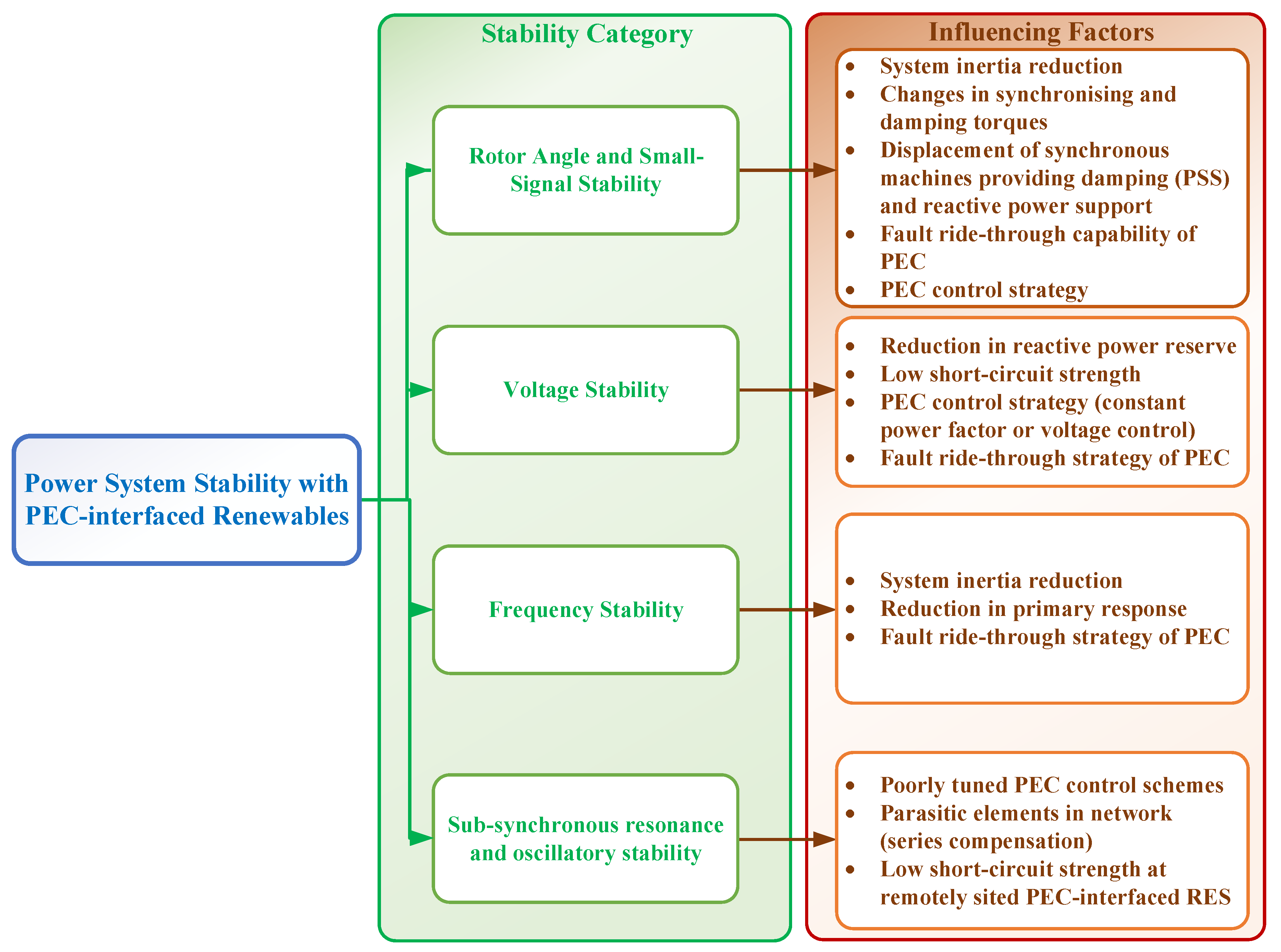
According to the review, power system stability has affected both positively and negatively by integration of PEC-interfaced renewable power generation. In summary, the key influencing factors for each stability category can be summarized as presented in Figure 17.
According to Figure 17, decrease in system inertia, reduction in reactive power reserve, PEC FRT capability/strategy, and system short-circuit strength [17] are playing key roles in affecting stability of the PEC-interfaced renewable rich power grids. Since power grids are gradually moving towards 100% renewable energy-based power grids, significantly high penetration levels of PEC-interfaced renewables are expected to be operating in power grids in future. In particular, existing fossil fuel-based power grids are likely to be operated with 100% PEC-interfaced RES in future, while the power grids having traditional hydropower plants will also have significant penetration levels of PEC-interfaced generation sources in the future. Therefore, considering these facts, it is essential to pay more attention on improving power grid stability with PEC-interfaced renewables.
In 100% PEC-interfaced power grids, the inverter capability is of paramount importance. Therefore, it is essential to conduct further studies on power system stability with various penetration levels of inverter-based technologies (i.e., grid-following and grid-forming inverters). For example, to operate a 100% PEC-interfaced power grid, the grid-forming type inverters are required, therefore future stability studies should explicitly consider both the grid-forming and grid following type inverters for power grids.
The FRT capability of PEC is also an important factor when operating power grids with 100% PEC-interfaced renewable power generation. The FRT capability ensures the PEC-interfaced generation are connected to the power grid during network faults. Sometimes, power networks could be subjected to multiple faults, hence it is important to ensure PEC-interfaced generator units remain connected during multiple faults. Also, it is important to ramp-up the generation following the clearance of the fault. These aspects must be thoroughly studied in order to ensure stability of 100% PEC-interfaced power grids. Also, other than connectivity of the PEC-interfaced source during the fault, more FRT requirements must be defined for active and reactive power response following fault clearance, etc. Enhanced FRT schemes could improve the power system stability as shown in Figure 18.
As shown in Figure 18, improved active power response following fault clearance could improve the frequency and rotor-angle stability as it could lower the power imbalance in the network during the post-fault period, while the improved reactive power response could improve the voltage and rotor-angle stability as it could improve the network voltage recovery during the post-fault period.
Power grid architecture is also undergoing a rapid transformation. As some power grids are rapidly evolving into a decentralized generation portfolio (e.g., small-scale rooftop solar-PV), hence it is essential to analyze power grid stability with high penetration of small-scale PEC-interfaced generation units in power grids. In addition, a large-scale multi-terminal direct current (MTDC) power grid is being built in parallel to the traditional AC power grid to transmit the renewable energy generated from the offshore and remote locations in the power grid. These emerging hybrid AC/DC power grids are posing new stability challenges, such as resonance and oscillatory stability issues. Therefore, since power grids are transforming to hybrid AC/DC power grids, advanced stability studies are required to characterize and understand the stability of these emerging power grid architectures.

10. Conclusions

During the past two decades, PEC-interfaced RES have significantly influenced the power system stability landscape, which is apparent from the various incidents happened in power networks across the world and stability studies conducted with the PEC-interfaced RES. This review has identified that several influencing factors (reduction in synchronous inertia, reduction in dynamic reactive power reserve, low short-circuit strength, and FRT capability) could affect multiple stability categories in power networks. Therefore, system operators should implement stability improvement strategies in a coordinated manner, such that the impact of key influencing factors could be mitigated, hence, overall system stability of the power network could be improved. FRT strategy/capability of PEC-interfaced RES is one of the major influencing factors for stability, by stipulating advanced capabilities for PEC-interfaced RES, such as active and reactive power recovery profiles following faults, multiple stability issues could be dramatically improved. This is particularly important, since many power networks are currently investigating the feasibility of operating power grids with 100% PEC-interfaced RES. Finally, power system operators must also consider the emerging structural changes in the power grid when investigating stability issues for future power grids by detailed modelling of PEC systems (e.g., multi-terminal converters) in stability simulations.

Author Contributions

Review of rotor angle stability, voltage stability, sub-synchronous resonance, and discussion by L.M.; review of fault ride-through by A.S.; review of frequency stability by J.S.B.; review of stability of hybrid AC/DC power grids by M.G., review of fault ride-through by E.R.C.D.; and review of fault ride-through strategies by R.B.A.C. All authors have read and agreed to the published version of the manuscript.

Funding

There is no funding to be reported for this publication.

Conflicts of Interest

The authors declare no conflicts of interest.

Abbreviations

List of Acronyms
ACEArea control error
AGCAutomatic generation control
AVRAutomatic voltage regulator
BCBraking chopper
BESSBattery energy storage system
DFIGDoubly-fed induction generator
DVSDynamic voltage support
ERCOTElectric Reliability Council of Texas
ESSEnergy storage system
FCLFault-current limiter
FFRFast frequency response
FRTFault ride-through
GSCGrid-side converter
HVDCHigh voltage direct current
IGBTInsulated gate bipolar transistor
LTVSLong-term voltage stability
LVRTLow voltage ride-through
MMCModular multilevel converter
MNCModified nominal power
MTDCMulti-terminal direct current
PCCPoint of common coupling
PECPower electronic converter
PLLPhase-locked loop
PMSGPermanent magnet synchronous generator
PMUPhasor measurement unit
PVPhotovoltaic
RESRenewable energy sources
RoCoFRate-of-change-of-frequency
RSCRotor-side converter
SCADASupervisory control and data acquisition
SFCLSuperconducting fault current limiter
SMESSuperconducting magnetic energy storage
SSCISub-synchronous control interaction
SSRSub-synchronous resonance
STATCOMStatic-synchronous compensator
STVSShort-term voltage stability
SVCStatic VAr Compensator
UCTEUnion for the Co-ordination of Transmission of Electricity
VSCVoltage source converter
WECSWind energy conversion system

Appendix A

Figure A1. Nine (9) bus system network model.
Energies 13 03441 g0a1

Appendix B

Figure A2. Two (2) bus system network model.
Energies 13 03441 g0a2

References

  1. Global Wind Report 2019; Global Wind Energy Council (GWEC): Brussels, Belgium, 2020.
  2. World Now has 583.5 GW of Operational PV. Available online: https://www.pv-magazine.com/2020/04/06/world-now-has-583-5-gw-of-operational-pv/ (accessed on 19 May 2020).
  3. Guerrero, J.M.; Blaabjerg, F.; Zhelev, T.; Hemmes, K.; Monmasson, E.; Jemei, S.; Comech, M.P.; Granadino, R.; Frau, J.I. Distributed Generation: Toward a New Energy Paradigm. IEEE Ind. Electron. Mag. 2010, 4, 52–64. [Google Scholar] [CrossRef]
  4. Baños, R.; Manzano-Agugliaro, F.; Montoya, F.G.; Gil, C.; Alcayde, A.; Gómez, J. Optimization methods applied to renewable and sustainable energy: A review. Renew. Sustain. Energy Rev. 2011, 15, 1753–1766. [Google Scholar] [CrossRef]
  5. Dincer, I. Renewable energy and sustainable development: A crucial review. Renew. Sustain. Energy Rev. 2000, 4, 157–175. [Google Scholar] [CrossRef]
  6. AEMO. Renewable Integration Study: Stage 1 Report; Australian Energy Market Operator: Melbourne, Australia, 2020; p. 75. [Google Scholar]
  7. Annakage, U.D.; Mehrizi-Sani, A.; Rajapakse, A.; Hauser, C.; Bhargava, B.; Wadduwage, D.P.; Chauduri, N.R.; Ribeiro Campos Andrade, S.; Perez Castro, J.; Chakrabortty, A.; et al. Application of Phasor Measurement Units for Monitoring Power System Dynamic Performance; CIGRÉ: Paris, France, 2017. [Google Scholar]
  8. O’Sullivan, J.; Rogers, A.; Flynn, D.; Smith, P.; Mullane, A.; O’Malley, M. Studying the Maximum Instantaneous Non-Synchronous Generation in an Island System—Frequency Stability Challenges in Ireland. IEEE Trans. Power Syst. 2014, 29, 2943–2951. [Google Scholar] [CrossRef] [Green Version]
  9. Matevosyan, J. Implementation of Inertia Monitoring in ERCOT—What’s It All About? 2018. Available online: https://www.esig.energy/implementation-of-inertia-monitoring-in-ercot-whats-it-all-about/ (accessed on 19 May 2020).
  10. EirGrid. Operational Constraints Update; EirGrid: Dublin, Ireland, 2019. [Google Scholar]
  11. Australian Energy Market Operator (AEMO). Inertia Requirements Methodology: Inertia Requirements & Shortfalls; Australian Energy Market Operator (AEMO): Melbourne, Australia, 2018; p. 46. [Google Scholar]
  12. Wen, Y.; Chung, C.Y.; Shuai, Z.; Che, L.; Xiao, Y.; Liu, X. Towards Flexible Risk-Limiting Operation of Multi-Terminal HVDC Grids with Vast Wind Generation. IEEE Trans. Sustain. Energy 2019, 1. [Google Scholar] [CrossRef]
  13. Chachar, F.A.; Bukhari, S.S.H.; Mangi, F.H.; Macpherson, D.E.; Harrison, G.P.; Bukhsh, W.; Ro, J.-S. Hierarchical Control Implementation for Meshed AC/Multi-Terminal DC Grids with Offshore Windfarms Integration. IEEE Access 2019, 7, 142233–142245. [Google Scholar] [CrossRef]
  14. Gu, M.; Meegahapola, L.; Wong, K.L. Damping Performance Analysis and Control of Hybrid AC/Multi-Terminal DC Power Grids. IEEE Access 2019, 7, 118712–118726. [Google Scholar] [CrossRef]
  15. Stieneker, M.; De Doncker, R.W. Medium-voltage DC distribution grids in urban areas. In Proceedings of the 2016 IEEE 7th International Symposium on Power Electronics for Distributed Generation Systems (PEDG), Vancouver, BC, Canada, 27–30 June 2016; pp. 1–7. [Google Scholar]
  16. Fox, B.; Bryans, L.; Flynn, D.; Jenkins, N.; Milborrow, D.; O’Malley, M.; Watson, R.; Anaya-Lara, O. Wind Power Integration: Connection and System Operational Aspects; The Institution of Engineering and Technology: London, UK, 2014; ISBN 978-1-84919-494-5. [Google Scholar]
  17. Meegahapola, L.; Datta, M.; Nutkani, I.; Conroy, J. Role of fault ride-through strategies for power grids with 100% power electronic-interfaced distributed renewable energy resources. WIREs Energy Environ. 2018, 7, e292. [Google Scholar] [CrossRef]
  18. Kundur, P.; Paserba, J.; Ajjarapu, V.; Andersson, G.; Bose, A.; Canizares, C.; Hatziargyriou, N.; Hill, D.; Stankovic, A.; Taylor, C.; et al. Definition and classification of power system stability IEEE/CIGRE joint task force on stability terms and definitions. IEEE Trans. Power Syst. 2004, 19, 1387–1401. [Google Scholar] [CrossRef]
  19. Meegahapola, L.; Flynn, D. Impact on transient and frequency stability for a power system at very high wind penetration. In Proceedings of the IEEE PES General Meeting, Providence, RI, USA, 25–29 July 2010; pp. 1–8. [Google Scholar]
  20. Nunes, M.V.A.; Lopes, J.A.P.; Zurn, H.H.; Bezerra, U.H.; Almeida, R.G. Influence of the variable-speed wind generators in transient stability margin of the conventional generators integrated in electrical grids. IEEE Trans. Energy Convers. 2004, 19, 692–701. [Google Scholar] [CrossRef] [Green Version]
  21. Meegahapola, L.; Flynn, D.; Littler, T. Transient stability analysis of a power system with high wind penetration. In Proceedings of the 2008 43rd International Universities Power Engineering Conference, Padova, Italy, 1–4 September 2008; pp. 1–5. [Google Scholar]
  22. Gautam, D.; Vittal, V.; Harbour, T. Impact of Increased Penetration of DFIG-Based Wind Turbine Generators on Transient and Small Signal Stability of Power Systems. IEEE Trans. Power Syst. 2009, 24, 1426–1434. [Google Scholar] [CrossRef]
  23. Shi, L.; Dai, S.; Ni, Y.; Yao, L.; Bazargan, M. Transient stability of power systems with high penetration of DFIG based wind farms. In Proceedings of the 2009 IEEE Power Energy Society General Meeting, Calgary, AB, Canada, 26–30 July 2009; pp. 1–6. [Google Scholar]
  24. Munkhchuluun, E.; Meegahapola, L.; Vahidnia, A. Impact on rotor angle stability with high solar-PV generation in power networks. In Proceedings of the 2017 IEEE PES Innovative Smart Grid Technologies Conference Europe (ISGT-Europe), Torino, Italy, 26–29 September 2017; pp. 1–6. [Google Scholar]
  25. Vittal, E.; O’Malley, M.; Keane, A. Rotor Angle Stability with High Penetrations of Wind Generation. IEEE Trans. Power Syst. 2012, 27, 353–362. [Google Scholar] [CrossRef]
  26. Mitra, A.; Chatterjee, D. Active Power Control of DFIG-Based Wind Farm for Improvement of Transient Stability of Power Systems. IEEE Trans. Power Syst. 2016, 31, 82–93. [Google Scholar] [CrossRef]
  27. Munkhchuluun, E.; Meegahapola, L.; Vahidnia, A. The Large Disturbance Rotor Angle Stability with DFIG Wind Farms. In Proceedings of the 2019 9th International Conference on Power and Energy Systems (ICPES), Perth, Australia, 10–12 December 2019; pp. 1–6. [Google Scholar]
  28. Yousefian, R.; Bhattarai, R.; Kamalasadan, S. Transient Stability Enhancement of Power Grid with Integrated Wide Area Control of Wind Farms and Synchronous Generators. IEEE Trans. Power Syst. 2017, 32, 4818–4831. [Google Scholar] [CrossRef]
  29. Darabian, M.; Jalilvand, A. Improving power system stability in the presence of wind farms using STATCOM and predictive control strategy. IET Renew. Power Gener. 2018, 12, 98–111. [Google Scholar] [CrossRef]
  30. Meegahapola, L.G.; Littler, T.; Flynn, D. Decoupled-DFIG Fault Ride-Through Strategy for Enhanced Stability Performance During Grid Faults. IEEE Trans. Sustain. Energy 2010, 1, 152–162. [Google Scholar] [CrossRef] [Green Version]
  31. Edrah, M.; Lo, K.L.; Anaya-Lara, O. Impacts of High Penetration of DFIG Wind Turbines on Rotor Angle Stability of Power Systems. IEEE Trans. Sustain. Energy 2015, 6, 759–766. [Google Scholar] [CrossRef] [Green Version]
  32. Papadopoulos, P.N.; Milanović, J.V. Probabilistic Framework for Transient Stability Assessment of Power Systems with High Penetration of Renewable Generation. IEEE Trans. Power Syst. 2017, 32, 3078–3088. [Google Scholar] [CrossRef] [Green Version]
  33. Diaz-Alzate, A.F.; Candelo-Becerra, J.E.; Villa Sierra, J.F. Transient Stability Prediction for Real-Time Operation by Monitoring the Relative Angle with Predefined Thresholds. Energies 2019, 12, 838. [Google Scholar] [CrossRef] [Green Version]
  34. Wu, Y.; Badesa, L.; Musavi, M.T.; Lerley, P. Monitoring power system transient stability using synchrophasor data. In Proceedings of the 2015 IEEE Power Energy Society General Meeting, Denver, CO, USA, 26–30 July 2015; pp. 1–5. [Google Scholar]
  35. Lee, D.-J.; Wang, L. Small-Signal Stability Analysis of an Autonomous Hybrid Renewable Energy Power Generation/Energy Storage System Part I: Time-Domain Simulations. IEEE Trans. Energy Convers. 2008, 23, 311–320. [Google Scholar] [CrossRef]
  36. Xi, X.; Geng, H.; Yang, G. Enhanced model of the doubly fed induction generator-based wind farm for small-signal stability studies of weak power system. IET Renew. Power Gener. 2014, 8, 765–774. [Google Scholar] [CrossRef]
  37. Bu, S.Q.; Du, W.; Wang, H.F.; Chen, Z.; Xiao, L.Y.; Li, H.F. Probabilistic Analysis of Small-Signal Stability of Large-Scale Power Systems as Affected by Penetration of Wind Generation. IEEE Trans. Power Syst. 2012, 27, 762–770. [Google Scholar] [CrossRef]
  38. Anderson, P.; Fouad, A.A. Power System Control and Stability, 1st ed.; Iowa State University Press: Ames, IA, USA, 1977. [Google Scholar]
  39. Oudalov, A.; Chartouni, D.; Ohler, C. Optimizing a Battery Energy Storage System for Primary Frequency Control. IEEE Trans. Power Syst. 2007, 22, 1259–1266. [Google Scholar] [CrossRef]
  40. Galus, M.D.; Koch, S.; Andersson, G. Provision of Load Frequency Control by PHEVs, Controllable Loads, and a Cogeneration Unit. IEEE Trans. Ind. Electron. 2011, 58, 4568–4582. [Google Scholar] [CrossRef]
  41. Wang, Y.; Delille, G.; Bayem, H.; Guillaud, X.; Francois, B. High Wind Power Penetration in Isolated Power Systems—Assessment of Wind Inertial and Primary Frequency Responses. IEEE Trans. Power Syst. 2013, 28, 2412–2420. [Google Scholar] [CrossRef]
  42. Lalor, G.; Mullane, A.; O’Malley, M. Frequency control and wind turbine technologies. IEEE Trans. Power Syst. 2005, 20, 1905–1913. [Google Scholar] [CrossRef]
  43. Molina-García, A.; Bouffard, F.; Kirschen, D.S. Decentralized Demand-Side Contribution to Primary Frequency Control. IEEE Trans. Power Syst. 2011, 26, 411–419. [Google Scholar] [CrossRef]
  44. Yingcheng, X.; Nengling, T. Review of contribution to frequency control through variable speed wind turbine. Renew. Energy 2011, 36, 1671–1677. [Google Scholar] [CrossRef]
  45. Rebours, Y.G.; Kirschen, D.S.; Trotignon, M.; Rossignol, S. A Survey of Frequency and Voltage Control Ancillary Services—Part I: Technical Features. IEEE Trans. Power Syst. 2007, 22, 350–357. [Google Scholar] [CrossRef]
  46. Blaabjerg, F.; Chen, Z.; Kjaer, S.B. Power electronics as efficient interface in dispersed power generation systems. IEEE Trans. Power Electron. 2004, 19, 1184–1194. [Google Scholar] [CrossRef]
  47. Carrasco, J.M.; Franquelo, L.G.; Bialasiewicz, J.T.; Galvan, E.; PortilloGuisado, R.C.; Prats, M.A.M.; Leon, J.I.; Moreno-Alfonso, N. Power-Electronic Systems for the Grid Integration of Renewable Energy Sources: A Survey. IEEE Trans. Ind. Electron. 2006, 53, 1002–1016. [Google Scholar] [CrossRef]
  48. Ulbig, A.; Borsche, T.S.; Andersson, G. Impact of Low Rotational Inertia on Power System Stability and Operation. IFAC Proc. Vol. 2014, 47, 7290–7297. [Google Scholar] [CrossRef] [Green Version]
  49. Quintero, J.; Vittal, V.; Heydt, G.T.; Zhang, H. The Impact of Increased Penetration of Converter Control-Based Generators on Power System Modes of Oscillation. IEEE Trans. Power Syst. 2014, 29, 2248–2256. [Google Scholar] [CrossRef]
  50. Li, W.; Joós, G.; Abbey, C. Wind Power Impact on System Frequency Deviation and an ESS based Power Filtering Algorithm Solution. In Proceedings of the 2006 IEEE PES Power Systems Conference and Exposition, Atlanta, GA, USA, 29 October–1 November 2006; pp. 2077–2084. [Google Scholar]
  51. Lei, Y.; Mullane, A.; Lightbody, G.; Yacamini, R. Modeling of the wind turbine with a doubly fed induction generator for grid integration studies. IEEE Trans. Energy Convers. 2006, 21, 257–264. [Google Scholar] [CrossRef]
  52. Ekanayake, J.; Jenkins, N. Comparison of the response of doubly fed and fixed-speed induction generator wind turbines to changes in network frequency. IEEE Trans. Energy Convers. 2004, 19, 800–802. [Google Scholar] [CrossRef]
  53. Morren, J.; de Haan, S.W.H.; Kling, W.L.; Ferreira, J.A. Wind turbines emulating inertia and supporting primary frequency control. IEEE Trans. Power Syst. 2006, 21, 433–434. [Google Scholar] [CrossRef]
  54. Tan, Y.; Meegahapola, L.; Muttaqi, K.M. A Suboptimal Power-Point-Tracking-Based Primary Frequency Response Strategy for DFIGs in Hybrid Remote Area Power Supply Systems. IEEE Trans. Energy Convers. 2016, 31, 93–105. [Google Scholar] [CrossRef]
  55. Ruttledge, L.; Flynn, D. Emulated Inertial Response from Wind Turbines: Gain Scheduling and Resource Coordination. IEEE Trans. Power Syst. 2016, 31, 3747–3755. [Google Scholar] [CrossRef]
  56. Arani, M.F.M.; El-Saadany, E.F. Implementing Virtual Inertia in DFIG-Based Wind Power Generation. IEEE Trans. Power Syst. 2013, 28, 1373–1384. [Google Scholar] [CrossRef]
  57. Dreidy, M.; Mokhlis, H.; Mekhilef, S. Inertia response and frequency control techniques for renewable energy sources: A review. Renew. Sustain. Energy Rev. 2017, 69, 144–155. [Google Scholar] [CrossRef]
  58. Wang, Y.; Meng, J.; Zhang, X.; Xu, L. Control of PMSG-Based Wind Turbines for System Inertial Response and Power Oscillation Damping. IEEE Trans. Sustain. Energy 2015, 6, 565–574. [Google Scholar] [CrossRef] [Green Version]
  59. Zhang, X.; Zhu, Z.; Fu, Y.; Shen, W. Multi-objective virtual inertia control of renewable power generator for transient stability improvement in interconnected power system. Int. J. Electr. Power Energy Syst. 2020, 117, 105641. [Google Scholar] [CrossRef]
  60. Morren, J.; Pierik, J.; de Haan, S.W.H. Inertial response of variable speed wind turbines. Electr. Power Syst. Res. 2006, 76, 980–987. [Google Scholar] [CrossRef]
  61. Van de Vyver, J.; De Kooning, J.D.M.; Meersman, B.; Vandevelde, L.; Vandoorn, T.L. Droop Control as an Alternative Inertial Response Strategy for the Synthetic Inertia on Wind Turbines. IEEE Trans. Power Syst. 2016, 31, 1129–1138. [Google Scholar] [CrossRef]
  62. Vidyanandan, K.V.; Senroy, N. Primary frequency regulation by deloaded wind turbines using variable droop. IEEE Trans. Power Syst. 2013, 28, 837–846. [Google Scholar] [CrossRef]
  63. Díaz-González, F.; Sumper, A.; Gomis-Bellmunt, O.; Villafáfila-Robles, R. A review of energy storage technologies for wind power applications. Renew. Sustain. Energy Rev. 2012, 16, 2154–2171. [Google Scholar] [CrossRef]
  64. Gomez, L.A.G.; Grilo, A.P.; Salles, M.B.C.; Sguarezi Filho, A.J. Combined Control of DFIG-Based Wind Turbine and Battery Energy Storage System for Frequency Response in Microgrids. Energies 2020, 13, 894. [Google Scholar] [CrossRef] [Green Version]
  65. Tan, Y.; Muttaqi, K.M.; Ciufo, P.; Meegahapola, L. Enhanced Frequency Response Strategy for a PMSG-Based Wind Energy Conversion System Using Ultracapacitor in Remote Area Power Supply Systems. IEEE Trans. Ind. Appl. 2017, 53, 549–558. [Google Scholar] [CrossRef] [Green Version]
  66. Tan, Y.; Muttaqi, K.M.; Ciufo, P.; Meegahapola, L.; Guo, X.; Chen, B.; Chen, H. Enhanced Frequency Regulation Using Multilevel Energy Storage in Remote Area Power Supply Systems. IEEE Trans. Power Syst. 2019, 34, 163–170. [Google Scholar] [CrossRef]
  67. Datta, U.; Kalam, A.; Shi, J. Battery Energy Storage System for Aggregated Inertia-Droop Control and a Novel Frequency Dependent State-of-Charge Recovery. Energies 2020, 13, 2003. [Google Scholar] [CrossRef] [Green Version]
  68. Akbarimajd, A.; Olyaee, M.; Sobhani, B.; Shayeghi, H. Nonlinear Multi-Agent Optimal Load Frequency Control Based on Feedback Linearization of Wind Turbines. IEEE Trans. Sustain. Energy 2019, 10, 66–74. [Google Scholar] [CrossRef]
  69. Datta, M.; Senjyu, T.; Yona, A.; Funabashi, T.; Kim, C.-H. A Coordinated Control Method for Leveling PV Output Power Fluctuations of PV–Diesel Hybrid Systems Connected to Isolated Power Utility. IEEE Trans. Energy Convers. 2009, 24, 153–162. [Google Scholar] [CrossRef]
  70. Poullikkas, A. A comparative overview of large-scale battery systems for electricity storage. Renew. Sustain. Energy Rev. 2013, 27, 778–788. [Google Scholar] [CrossRef]
  71. Yi, Z.; Dong, W.; Etemadi, A.H. A Unified Control and Power Management Scheme for PV-Battery-Based Hybrid Microgrids for Both Grid-Connected and Islanded Modes. IEEE Trans. Smart Grid 2018, 9, 5975–5985. [Google Scholar] [CrossRef]
  72. Rahmann, C.; Castillo, A. Fast Frequency Response Capability of Photovoltaic Power Plants: The Necessity of New Grid Requirements and Definitions. Energies 2014, 7, 6306–6322. [Google Scholar] [CrossRef]
  73. Miller, N.W.; Sanchez-Gasca, J.J. Modeling of GE Wind Turbine-Generators for Grid Studies; General Electric International, Inc. (GE): Cincinnati, OH, USA, 2008. [Google Scholar]
  74. Rodriguez, J.M.; Fernandez, J.L.; Beato, D.; Iturbe, R.; Usaola, J.; Ledesma, P.; Wilhelmi, J.R. Incidence on power system dynamics of high penetration of fixed speed and doubly fed wind energy systems: Study of the Spanish case. IEEE Trans. Power Syst. 2002, 17, 1089–1095. [Google Scholar] [CrossRef]
  75. Vittal, E.; O’Malley, M.; Keane, A. A Steady-State Voltage Stability Analysis of Power Systems with High Penetrations of Wind. IEEE Trans. Power Syst. 2010, 25, 433–442. [Google Scholar] [CrossRef]
  76. Sravan Kumar, V.S.; Krishna Reddy, K.; Thukaram, D. Coordination of Reactive Power in Grid-Connected Wind Farms for Voltage Stability Enhancement. IEEE Trans. Power Syst. 2014, 29, 2381–2390. [Google Scholar] [CrossRef]
  77. Adetokun, B.B.; Muriithi, C.M.; Ojo, J.O. Voltage stability assessment and enhancement of power grid with increasing wind energy penetration. Int. J. Electr. Power Energy Syst. 2020, 120, 105988. [Google Scholar] [CrossRef]
  78. Amarasekara, H.W.K.M.; Meegahapola, L.; Agalgaonkar, A.P.; Perera, S. Impact of renewable power integration on VQ stability margin. In Proceedings of the 2013 Australasian Universities Power Engineering Conference (AUPEC), Hobart, Australia, 29 September–3 October 2013; pp. 1–6. [Google Scholar]
  79. Wang, Y.; Chiang, H.-D.; Wang, T. A two-stage method for assessment of voltage stability in power system with renewable energy. In Proceedings of the 2013 IEEE Electrical Power Energy Conference, Halifax, NS, Canada, 21–23 August 2013; pp. 1–6. [Google Scholar]
  80. Amarasekara, H.W.K.M.; Agalgaonkar, A.P.; Perera, S.; Meegahapola, L. Placement of variable-speed wind power generators in power systems considering steady-state voltage stability. In Proceedings of the 2016 IEEE International Conference on Power System Technology (POWERCON), Wollongong, Australia, 28 September–1 October 2016; pp. 1–6. [Google Scholar]
  81. Keane, A.; Ochoa, L.F.; Vittal, E.; Dent, C.J.; Harrison, G.P. Enhanced Utilization of Voltage Control Resources with Distributed Generation. IEEE Trans. Power Syst. 2011, 26, 252–260. [Google Scholar] [CrossRef] [Green Version]
  82. Sarkar, M.N.I.; Meegahapola, L.G.; Datta, M. Reactive Power Management in Renewable Rich Power Grids: A Review of Grid-Codes, Renewable Generators, Support Devices, Control Strategies and Optimization Algorithms. IEEE Access 2018, 6, 41458–41489. [Google Scholar] [CrossRef]
  83. Amarasekara, K.; Meegahapola, L.G.; Agalgaonkar, A.; Perera, S. Impact of Variable Speed Wind Power Generators on Short-Term and Long-Term Voltage Stability. In Proceedings of the 14th International Workshop on Large-Scale Integration of Wind Power into Power Systems as well as on Transmission Networks for Offshore Wind Power Plants, Brussels, Belgium, 20–22 October 2015. [Google Scholar]
  84. Ullah, N.R.; Thiringer, T. Variable Speed Wind Turbines for Power System Stability Enhancement. IEEE Trans. Energy Convers. 2007, 22, 52–60. [Google Scholar] [CrossRef]
  85. Ullah, N.R.; Thiringer, T.; Karlsson, D. Voltage and Transient Stability Support by Wind Farms Complying with the E. ON Netz Grid Code. IEEE Trans. Power Syst. 2007, 22, 1647–1656. [Google Scholar] [CrossRef]
  86. Meegahapola, L.; Littler, T. Characterisation of large disturbance rotor angle and voltage stability in interconnected power networks with distributed wind generation. IET Renew. Power Gener. 2015, 9, 272–283. [Google Scholar] [CrossRef] [Green Version]
  87. Londero, R.R.; Affonso, C.D.M.; Vieira, J.P.A. Long-Term Voltage Stability Analysis of Variable Speed Wind Generators. IEEE Trans. Power Syst. 2015, 30, 439–447. [Google Scholar] [CrossRef]
  88. Amarasekara, K.; Meegahapola, L.G.; Agalgaonkar, A.P.; Perera, S. Characterisation of long-term voltage stability with variable-speed wind power generation. Transm. Distrib. IET Gener. 2017, 11, 1848–1855. [Google Scholar] [CrossRef]
  89. Munkhchuluun, E.; Meegahapola, L.; Vahidnia, A. Long-term voltage stability with large-scale solar-photovoltaic (PV) generation. Int. J. Electr. Power Energy Syst. 2020, 117, 105663. [Google Scholar] [CrossRef]
  90. Muljadi, E.; Zhang, Y.C. Wind Power Plant Voltage Stability Evaluation: Preprint. In Proceedings of the International Conference on Wind Energy Grid-Adaptive Technologies, Jeju, Korea, 20–22 October 2014. [Google Scholar]
  91. Perez, A.; Karatas, B.C.; Jóhannsson, H.; Østergaard, J. Considering wind speed variability in real-time voltage stability assessment using Thévenin equivalent methods. In Proceedings of the 2017 IEEE Manchester PowerTech, Manchester, UK, 18–22 June 2017; pp. 1–6. [Google Scholar]
  92. Perez, A.; Jóhannsson, H.; Østergaard, J. Wind farms generation limits and its impact in real-time voltage stability assessment. In Proceedings of the 2015 IEEE Eindhoven PowerTech, Eindhoven, The Netherlands, 29 June–2 July 2015; pp. 1–5. [Google Scholar]
  93. Thilakarathne, C.; Meegahapola, L.; Fernando, N. Real-time voltage stability assessment using phasor measurement units: Influence of synchrophasor estimation algorithms. Int. J. Electr. Power Energy Syst. 2020, 119, 105933. [Google Scholar] [CrossRef]
  94. Meegahapola, L.G.; Bu, S.; Wadduwage, D.P.; Chung, C.Y.; Yu, X. Review on Oscillatory Stability in Power Grids with Renewable Energy Sources: Monitoring, Analysis, and Control using Synchrophasor Technology. IEEE Trans. Ind. Electron. 2020, 1. [Google Scholar] [CrossRef]
  95. Meegahapola, L.G.; Flynn, D.; Kennedy, J.; Littler, T. Impact of wind generation mix on transient stability for an interconnected power system. In Proceedings of the Wind Energy Conference (EWEC) 2009, Marseille, France, 16–19 March 2009. [Google Scholar]
  96. Hughes, F.M.; Anaya-Lara, O.; Jenkins, N.; Strbac, G. A power system stabilizer for DFIG-based wind generation. IEEE Trans. Power Syst. 2006, 21, 763–772. [Google Scholar] [CrossRef]
  97. Miao, Z.; Fan, L.; Osborn, D.; Yuvarajan, S. Control of DFIG-Based Wind Generation to Improve Interarea Oscillation Damping. IEEE Trans. Energy Convers. 2009, 24, 415–422. [Google Scholar] [CrossRef]
  98. Fan, L.; Yin, H.; Miao, Z. On Active/Reactive Power Modulation of DFIG-Based Wind Generation for Interarea Oscillation Damping. IEEE Trans. Energy Convers. 2011, 26, 513–521. [Google Scholar] [CrossRef]
  99. Irwin, G.D.; Jindal, A.K.; Isaacs, A.L. Sub-synchronous control interactions between type 3 wind turbines and series compensated AC transmission systems. In Proceedings of the 2011 IEEE Power and Energy Society General Meeting, Detroit, MI, USA, 24–28 July 2011; pp. 1–6. [Google Scholar]
  100. Adams, J.; Carter, C.; Huang, S.-H. ERCOT experience with Sub-synchronous Control Interaction and proposed remediation. In Proceedings of the PES TD 2012, Orlando, FL, USA, 7–10 May 2012; pp. 1–5. [Google Scholar]
  101. Leon, A.E.; Solsona, J.A. Sub-Synchronous Interaction Damping Control for DFIG Wind Turbines. IEEE Trans. Power Syst. 2015, 30, 419–428. [Google Scholar] [CrossRef]
  102. Suriyaarachchi, D.H.R.; Annakkage, U.D.; Karawita, C.; Jacobson, D.A. A Procedure to Study Sub-Synchronous Interactions in Wind Integrated Power Systems. IEEE Trans. Power Syst. 2013, 28, 377–384. [Google Scholar] [CrossRef]
  103. Miao, Z. Impedance-Model-Based SSR Analysis for Type 3 Wind Generator and Series-Compensated Network. IEEE Trans. Energy Convers. 2012, 27, 984–991. [Google Scholar] [CrossRef]
  104. Xie, X.; Zhang, X.; Liu, H.; Liu, H.; Li, Y.; Zhang, C. Characteristic Analysis of Subsynchronous Resonance in Practical Wind Farms Connected to Series-Compensated Transmissions. IEEE Trans. Energy Convers. 2017, 32, 1117–1126. [Google Scholar] [CrossRef]
  105. Hagh, M.T.; Khalili, T. A review of fault ride through of PV and wind renewable energies in grid codes. Int. J. Energy Res. 2019, 43, 1342–1356. [Google Scholar] [CrossRef]
  106. Castilla, M.; Miret, J.; Camacho, A.; Matas, J.; García de Vicuña, L. Voltage Support Control Strategies for Static Synchronous Compensators Under Unbalanced Voltage Sags. IEEE Trans. Ind. Electron. 2014, 61, 808–820. [Google Scholar] [CrossRef]
  107. Conroy, J.F.; Watson, R. Low-voltage ride-through of a full converter wind turbine with permanent magnet generator. IET Renew. Power Gener. 2007, 1, 182–189. [Google Scholar] [CrossRef]
  108. Yehia, D.M.; Mansour, D.-E.A.; Yuan, W. Fault Ride-Through Enhancement of PMSG Wind Turbines with DC Microgrids Using Resistive-Type SFCL. IEEE Trans. Appl. Supercond. 2018, 28, 1–5. [Google Scholar] [CrossRef]
  109. Nguyen, T.H.; Lee, D.-C. Advanced Fault Ride-Through Technique for PMSG Wind Turbine Systems Using Line-Side Converter as STATCOM. IEEE Trans. Ind. Electron. 2013, 60, 2842–2850. [Google Scholar] [CrossRef]
  110. Varma, R.; Rahman, S.A.; Vanderheide, T. New control of PV solar farm as STATCOM (PV-STATCOM) for increasing grid power transmission limits during night and day. IEEE Trans. Power Deliv. 2014, 30, 755–763. [Google Scholar] [CrossRef]
  111. Varma, R.K.; Maleki, H. PV Solar System Control as STATCOM (PV-STATCOM) for Power Oscillation Damping. IEEE Trans. Sustain. Energy 2019, 10, 1793–1803. [Google Scholar] [CrossRef]
  112. Howlader, A.M.; Senjyu, T. A comprehensive review of low voltage ride through capability strategies for the wind energy conversion systems. Renew. Sustain. Energy Rev. 2016, 56, 643–658. [Google Scholar] [CrossRef]
  113. Sahoo, S.; Mishra, A.; Chatterjee, K.; Sharma, C.K. Enhanced fault ride—Through ability of DFIG-based wind energy system using superconducting fault current limiter. In Proceedings of the 2017 4th International Conference on Power, Control Embedded Systems (ICPCES), Allahabad, India, 9–11 March 2017; pp. 1–5. [Google Scholar]
  114. Elshiekh, M.E.; Mansour, D.-E.A.; Azmy, A.M. Improving Fault Ride-Through Capability of DFIG-Based Wind Turbine Using Superconducting Fault Current Limiter. IEEE Trans. Appl. Supercond. 2013, 23, 5601204. [Google Scholar] [CrossRef]
  115. Ngamroo, I.; Karaipoom, T. Cooperative Control of SFCL and SMES for Enhancing Fault Ride Through Capability and Smoothing Power Fluctuation of DFIG Wind Farm. IEEE Trans. Appl. Supercond. 2014, 24, 1–4. [Google Scholar] [CrossRef]
  116. Marei, M.I.; El-Goharey, H.S.K.; Toukhy, R.M. Fault ride-through enhancement of fixed speed wind turbine using bridge-type fault current limiter. J. Electr. Syst. Inf. Technol. 2016, 3, 119–126. [Google Scholar] [CrossRef] [Green Version]
  117. Chen, L.; He, H.; Chen, H.; Wang, L.; Zhu, L.; Shu, Z.; Tang, F.; Yang, J. Study of a Modified Flux-Coupling-Type SFCL for Efficient Fault Ride-Through in a PMSG Wind Turbine Under Different Types of Faults. Can. J. Electr. Comput. Eng. 2017, 40, 189–200. [Google Scholar] [CrossRef]
  118. Yang, L.; Xu, Z.; Ostergaard, J.; Dong, Z.Y.; Wong, K.P. Advanced Control Strategy of DFIG Wind Turbines for Power System Fault Ride Through. IEEE Trans. Power Syst. 2012, 27, 713–722. [Google Scholar] [CrossRef] [Green Version]
  119. Sahoo, S.S.; Roy, A.; Chatterjee, K. Fault ride-through enhancement of wind energy conversion system adopting a mechanical controller. In Proceedings of the 2016 National Power Systems Conference (NPSC), Bhubaneswar, India, 19–21 December 2016; pp. 1–5. [Google Scholar]
  120. Kamel, R.M. Three fault ride through controllers for wind systems running in isolated micro-grid and Effects of fault type on their performance: A review and comparative study. Renew. Sustain. Energy Rev. 2014, 37, 698–714. [Google Scholar] [CrossRef]
  121. Meri, A.A.; Amara, Y.; Nichita, C. Impact of Fault Ride-Through on Wind Turbines Systems Design. In Proceedings of the 2018 7th International Conference on Renewable Energy Research and Applications (ICRERA), Paris, France, 14–17 October 2018; pp. 567–575. [Google Scholar]
  122. Justo, J.J.; Mwasilu, F.; Jung, J.-W. Doubly-fed induction generator based wind turbines: A comprehensive review of fault ride-through strategies. Renew. Sustain. Energy Rev. 2015, 45, 447–467. [Google Scholar] [CrossRef]
  123. Nasiri, M.; Milimonfared, J.; Fathi, S.H. A review of low-voltage ride-through enhancement methods for permanent magnet synchronous generator based wind turbines. Renew. Sustain. Energy Rev. 2015, 47, 399–415. [Google Scholar] [CrossRef]
  124. Sguarezi Filho, A.J.; de Oliveira Filho, M.E.; Ruppert Filho, E. A Predictive Power Control for Wind Energy. IEEE Trans. Sustain. Energy 2011, 2, 97–105. [Google Scholar] [CrossRef]
  125. Rini Ann Jerin, A.; Kaliannan, P.; Subramaniam, U. Improved fault ride through capability of DFIG based wind turbines using synchronous reference frame control based dynamic voltage restorer. ISA Trans. 2017, 70, 465–474. [Google Scholar] [CrossRef]
  126. Abad, G.; Lopez, J.; Rodriguez, M.; Marroyo, L.; Iwanski, G. Doubly Fed Induction Machine: Modeling and Control for Wind Energy Generation, 1st ed.; John Wiley & Sons: Hoboken, NJ, USA, 2011; ISBN 978-0-470-76865-5. [Google Scholar]
  127. Srinivas, V.L.; Singh, B.; Mishra, S. Fault Ride-Through Strategy for Two-Stage Grid-Connected Photovoltaic System Enabling Load Compensation Capabilities. IEEE Trans. Ind. Electron. 2019, 66, 8913–8924. [Google Scholar] [CrossRef]
  128. Wang, F.; Duarte, J.L.; Hendrix, M.A.M. Pliant Active and Reactive Power Control for Grid-Interactive Converters Under Unbalanced Voltage Dips. IEEE Trans. Power Electron. 2011, 26, 1511–1521. [Google Scholar] [CrossRef]
  129. Kawabe, K.; Tanaka, K. Impact of Dynamic Behavior of Photovoltaic Power Generation Systems on Short-Term Voltage Stability. IEEE Trans. Power Syst. 2015, 30, 3416–3424. [Google Scholar] [CrossRef]
  130. Lammert, G.; Premm, D.; Ospina, L.D.P.; Boemer, J.C.; Braun, M.; Van Cutsem, T. Control of Photovoltaic Systems for Enhanced Short-Term Voltage Stability and Recovery. IEEE Trans. Energy Convers. 2019, 34, 243–254. [Google Scholar] [CrossRef] [Green Version]
  131. Afshari, E.; Moradi, G.R.; Rahimi, R.; Farhangi, B.; Yang, Y.; Blaabjerg, F.; Farhangi, S. Control Strategy for Three-Phase Grid-Connected PV Inverters Enabling Current Limitation Under Unbalanced Faults. IEEE Trans. Ind. Electron. 2017, 64, 8908–8918. [Google Scholar] [CrossRef] [Green Version]
  132. Zhu, M.; Hang, L.; Li, G.; Jiang, X. Protected control method for power conversion interface under unbalanced operating conditions in AC/DC hybrid distributed grid. IEEE Trans. Energy Convers. 2015, 31, 57–68. [Google Scholar] [CrossRef]
  133. Zou, C.; Rao, H.; Xu, S.; Li, Y.; Li, W.; Chen, J.; Zhao, X.; Yang, Y.; Lei, B. Analysis of Resonance Between a VSC-HVDC Converter and the AC Grid. IEEE Trans. Power Electron. 2018, 33, 10157–10168. [Google Scholar] [CrossRef]
  134. Parker, S.G.; McGrath, B.P.; Holmes, D.G. Regions of Active Damping Control for LCL Filters. IEEE Trans. Ind. Appl. 2014, 50, 424–432. [Google Scholar] [CrossRef]
  135. Wang, X.; Blaabjerg, F.; Loh, P.C. Passivity-Based Stability Analysis and Damping Injection for Multiparalleled VSCs with LCL Filters. IEEE Trans. Power Electron. 2017, 32, 8922–8935. [Google Scholar] [CrossRef] [Green Version]
  136. Saeedifard, M.; Iravani, R. Dynamic Performance of a Modular Multilevel Back-to-Back HVDC System. IEEE Trans. Power Deliv. 2010, 25, 2903–2912. [Google Scholar] [CrossRef]
  137. Saad, H.; Guillaud, X.; Mahseredjian, J.; Dennetière, S.; Nguefeu, S. MMC Capacitor Voltage Decoupling and Balancing Controls. IEEE Trans. Power Deliv. 2015, 30, 704–712. [Google Scholar] [CrossRef]
  138. Mahmoudi, H.; Aleenejad, M.; Ahmadi, R. Modulated Model Predictive Control of Modular Multilevel Converters in VSC-HVDC Systems. IEEE Trans. Power Deliv. 2018, 33, 2115–2124. [Google Scholar] [CrossRef]
  139. Tu, Q.; Xu, Z.; Xu, L. Reduced Switching-Frequency Modulation and Circulating Current Suppression for Modular Multilevel Converters. IEEE Trans. Power Deliv. 2011, 26, 2009–2017. [Google Scholar] [CrossRef]
  140. Shah, R.; Preece, R.; Barnes, M. The Impact of Voltage Regulation of Multiinfeed VSC-HVDC on Power System Stability. IEEE Trans. Energy Convers. 2018, 33, 1614–1627. [Google Scholar] [CrossRef]
  141. Chen, X.; Wang, L.; Sun, H.; Chen, Y. Fuzzy Logic Based Adaptive Droop Control in Multiterminal HVDC for Wind Power Integration. IEEE Trans. Energy Convers. 2017, 32, 1200–1208. [Google Scholar] [CrossRef]
  142. Huang, Y.; Yuan, X.; Hu, J.; Zhou, P.; Wang, D. DC-Bus Voltage Control Stability Affected by AC-Bus Voltage Control in VSCs Connected to Weak AC Grids. IEEE J. Emerg. Sel. Top. Power Electron. 2016, 4, 445–458. [Google Scholar] [CrossRef]
  143. Wang, Y.; Zhou, Y.; Li, D.; Shao, D.; Cao, K.; Zhou, K.; Cai, D. The Influence of VSC–HVDC Reactive Power Control Mode on AC Power System Stability. Energies 2020, 13, 1677. [Google Scholar] [CrossRef] [Green Version]
  144. Zhou, J.Z.; Ding, H.; Fan, S.; Zhang, Y.; Gole, A.M. Impact of Short-Circuit Ratio and Phase-Locked-Loop Parameters on the Small-Signal Behavior of a VSC-HVDC Converter. IEEE Trans. Power Deliv. 2014, 29, 2287–2296. [Google Scholar] [CrossRef]
  145. Zhang, X.; Xia, D.; Fu, Z.; Wang, G.; Xu, D. An Improved Feedforward Control Method Considering PLL Dynamics to Improve Weak Grid Stability of Grid-Connected Inverters. IEEE Trans. Ind. Appl. 2018, 54, 5143–5151. [Google Scholar] [CrossRef]
  146. Zeni, L.; Eriksson, R.; Goumalatsos, S.; Altin, M.; Sørensen, P.; Hansen, A.; Kjær, P.; Hesselbæk, B. Power Oscillation Damping From VSC–HVDC Connected Offshore Wind Power Plants. IEEE Trans. Power Deliv. 2016, 31, 829–838. [Google Scholar] [CrossRef]
  147. Wang, W.; Barnes, M.; Marjanovic, O.; Cwikowski, O. Impact of DC Breaker Systems on Multiterminal VSC-HVDC Stability. IEEE Trans. Power Deliv. 2016, 31, 769–779. [Google Scholar] [CrossRef]
  148. Kirakosyan, A.; Moursi, M.S.E.; Khadkikar, V. Fault Ride Through and Grid Support Topology for the VSC-HVDC Connected Offshore Wind Farms. IEEE Trans. Power Deliv. 2017, 32, 1592–1604. [Google Scholar] [CrossRef]
  149. van der Meer, A.A.; Ndreko, M.; Gibescu, M.; van der Meijden, M.A.M.M. The Effect of FRT Behavior of VSC-HVDC-Connected Offshore Wind Power Plants on AC/DC System Dynamics. IEEE Trans. Power Deliv. 2016, 31, 878–887. [Google Scholar] [CrossRef]
  150. Silva, B.; Moreira, C.L.; Seca, L.; Phulpin, Y.; Pecas Lopes, J.A. Provision of Inertial and Primary Frequency Control Services Using Offshore Multiterminal HVDC Networks. IEEE Trans. Sustain. Energy 2012, 3, 800–808. [Google Scholar] [CrossRef]
  151. Xue, A.; Zhang, J.; Zhang, L.; Sun, Y.; Cui, J.; Wang, J. Transient Frequency Stability Emergency Control for the Power System Interconnected with Offshore Wind Power Through VSC-HVDC. IEEE Access 2020, 8, 53133–53140. [Google Scholar] [CrossRef]
  152. Li, Y.; Xu, Z.; Østergaard, J.; Hill, D.J. Coordinated Control Strategies for Offshore Wind Farm Integration via VSC-HVDC for System Frequency Support. IEEE Trans. Energy Convers. 2017, 32, 843–856. [Google Scholar] [CrossRef] [Green Version]
  153. Martínez Sanz, I.; Chaudhuri, B.; Strbac, G. Inertial Response from Offshore Wind Farms Connected Through DC Grids. IEEE Trans. Power Syst. 2015, 30, 1518–1527. [Google Scholar] [CrossRef]
  154. Carmona Sanchez, J.; Marjanovic, O.; Barnes, M.; Green, P.R. Secondary Model Predictive Control Architecture for VSC-HVDC Networks Interfacing Wind Power. IEEE Trans. Power Deliv. 2020, 1. [Google Scholar] [CrossRef] [Green Version]
Figure 1. Differing power system dynamics in electromagnetic and electromechanical timescales.
Energies 13 03441 g001
Figure 2. Categorization of stability studies conducted with power electronic converter (PEC)-interfaced renewables.
Energies 13 03441 g002
Figure 3. Rotor angle stability with wind generation; (a) G3 rotor angle following the fault for scenario-1, (b) G2 rotor angle following the fault for scenario-2. DFID—doubly-fed induction generator.
Energies 13 03441 g003
Figure 4. Eigenvalues for two wind integration scenarios and synchronous generator scenario.
Energies 13 03441 g004
Figure 5. Primary, secondary, and tertiary frequency control responses.
Energies 13 03441 g005
Figure 6. Secondary frequency control (AGC) scheme.
Energies 13 03441 g006
Figure 7. Predominant frequency control methods for wind and solar photovoltaic (PV) systems.
Energies 13 03441 g007
Figure 8. Frequency response with DFIG wind generation.
Energies 13 03441 g008
Figure 9. Representation of voltage stability as an equilibrium between source and load reactive power; (a) Stable case, (b) System moving towards voltage instability.
Energies 13 03441 g009
Figure 10. Q-V curves of bus-8 under three scenarios.
Energies 13 03441 g010
Figure 11. Wind farm connected to a series compensated line.
Energies 13 03441 g011
Figure 12. Illustration of a PEC-interfaced renewable energy sources (RES) with different fault ride-through (FRT) options.
Energies 13 03441 g012
Figure 13. DFIG FRT performance during a voltage dip using the demagnetizing current and predictive control method; (a) stator voltage, (b) active and reactive power, (c) stator currents.
Energies 13 03441 g013
Figure 14. Solar-PV system injecting reactive power during a voltage sag; (a) voltage, (b) current, (c) power.
Energies 13 03441 g014
Figure 15. A four-terminal hybrid AC/DC power network.
Energies 13 03441 g015
Figure 16. DC bus voltage performances under converter outage with different control schemes.
Energies 13 03441 g016
Figure 17. The key influencing factors of main stability categories with PEC-interfaced renewable generation.
Energies 13 03441 g017
Figure 18. Influence of the fault ride-through strategy on stability.
Energies 13 03441 g018
Table 1. Summary of stability issues and causes in hybrid AC/DC power grids.
OriginIssues and CausesReferences
Power electronic converterConverter hardwareHigh-frequency harmonics are caused by switching[131,132]
Resonance is caused by filter[107,108,109]
Capacitor voltage balancing and circulating current of MMC[110,111,112,113]
Converter softwareOverloading and disturbance are caused by converter voltage controller[140,143]
Resonance is caused by PLL[118,119]
Oscillations are caused by AVR[146]
Network protectionOscillations are caused by the DC breaker[147]
Undesired power flow in antiparallel diode[148]
Effects of FRT action[149]
Renewable energy sourceFrequency fluctuations are caused by randomness of RES[150,151]
Frequency and DC voltage variations are caused by low inertia of RES[126,127,128]