1. Introduction
In the 21st century, Renewable Energy Sources (RES) have acquired an unprecedented role [
1]. Governments are increasingly betting on clean energy to comply with international agreements. For example, India seeks the installation of 40,000 MW electricity generation capacity from renewable energy sources by 2022. In Argentina, one of the largest solar plants in Latin America is being built, the project will provide the grid 300 MW of power [
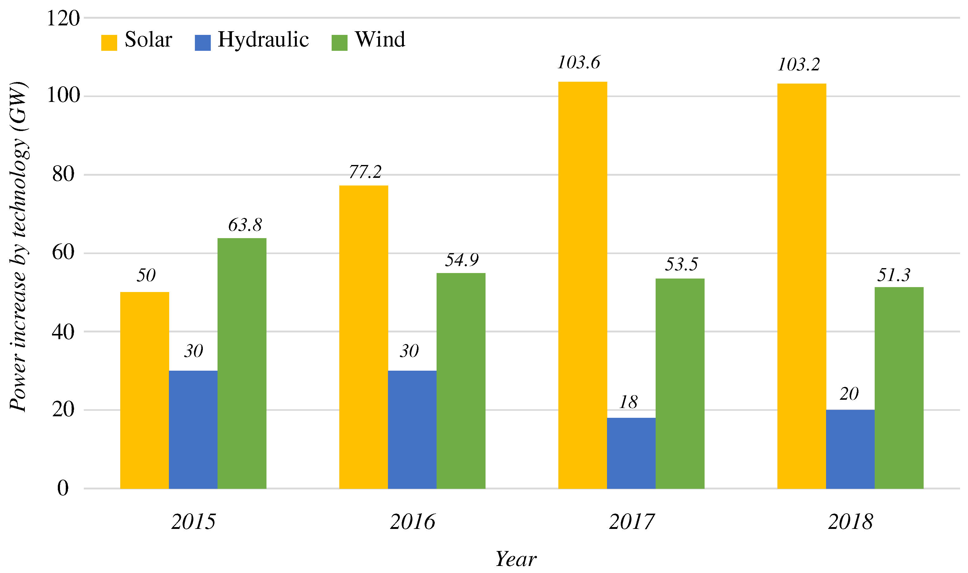
2]. The main RES are: hydraulic, wind and solar. In 2018, solar energy experienced an increase of 103.2 GW in global electricity production capacity over the previous year, for a total of 505 GW. However, electrical capacity from hydraulic and wind power only increased by 20 GW and 51.3 GW, respectively. A detailed description of the current status of RES is presented in [
3]. The greater use of Photovoltaic (PV) systems is, essentially, due to the decrease in cell production costs, which means that the return on investment occurs in less time. At present, solar energy is consolidated as a competitive option for both the industrial and residential sectors [
4].
Figure 1 shows the increase in electrical production per year of the main clean sources.
The advance in PV systems worldwide has caused a reduction in the cost of investments to generate electricity by this means. Gatta et al. in [
5] analyze the replacement of diesel generators by hybrid RES plants in Italy, where 500 kWp (Peak Power) PV power plant and a 1000 kW/500 kWh lithium-ion Battery Energy Storage System (BESS) were installed. However, to achieve widespread use of PV systems worldwide, this technology must be competitive in terms of cost compared to conventional methods. Certain estimates assure that the price of PV systems will decrease from USD 0.18/kWh in 2016 to USD 0.05/kWh in 2030 [
6]. This price actually contrasts with an average of USD 0.12/kWh for conventional energy sources.
Currently, the integration of BESS and PV systems has been efficiently achieved in certain applications. The authors in [
7] present a traction system based on obtaining solar energy stored in a BESS. The research proposes a solution based on PV for one of the most polluting sectors in the world. However, it is important to mention that the energy obtained from other RES is currently expanding. Wind farms are an alternative to the absence of sunlight at night. In this regard, the research [
8] offers a broad panorama of this technology use.
The efficiency and lifetime of the system are two aspects that directly affect the reduction of costs. Currently, there is a trend to oversize the PV array; thus, the nominal power of the array is greater than the nominal inverter power [
9,
10] and the converter gets more energy in the same period. The system as a whole will capture more energy during production periods. It is possible to oversize the panels considering that the price decreases approximately 13% [
11] each year; therefore, the cost of a greater PV string will be compensated with the energy captured.
The inverters are: Current-Source Inverter (CSI), Voltage-Source Inverter (VSI), or Impedance-Source Inverter (ZSI) [
12]. The VSI and CSI differ in the type of input element (capacitor or inductor) [
13]. The use of the inverters cover a wide range of applications, from power supplies to high-power industrial applications, certain examples are found in the literature [
14,
15,
16,
17,
18]. The DC/AC converters are also employed as intermediate stage between RES and the grid since they transform the Direct Current (DC) into Alternating Current (AC).
Sahan et al. in [
19] present a comparative study between VSI and CSI. Other classifications are line-switched or auto-switched; inverters for autonomous systems or inverters for grid-connected systems and single-phase (<5 kW) or three-phase (>5 kW). Traditional DC/AC converters, also called conventional inverters, are limited to only two output levels and require specific characteristics to achieve an adequate signal. For example, the two-level H-bridge topology uses a high-switching frequency to obtain low harmonic distortion at the output [
20]. The main disadvantages of traditional topologies are shown in
Table 1.
Multilevel topology has emerged to remove the limitations of traditional DC/AC converters. The main multilevel voltage-source schemes are: Neutral Point Clamped (NPC) [
21], Flying Capacitor (FC) [
22] and Cascaded (CMLI) [
23], although other topologies are also used to a lesser extent, such as Hexagram [
24] and Hybrid [
25]. The main difference between conventional topologies and multilevel inverters is the number of output levels, while traditional converters have only two levels of power at their output, multilevel inverters deliver more than two levels.
The development of multilevel inverters evolves together with the different control strategies. Nowadays, Model Predictive Control (MPC) is commonly used in the control area of these converters [
26]. Its effectiveness has been proved in various power converter topologies [
27]. Conventional control techniques such as Proportional-Integral (PI) [
28] or Proportional-Resonant (PR) controller [
29,
30] are also used. However, the control strategy depends on the topology and the application.
Although inverters have been previously studied in industrial applications [
31], the use of these converters in RES is a subject that presents its own challenges, trends and problems. Precisely, due to the current need for a greater use of RES and inverters as an interface for the injection of energy into the grid, the current state-of-the-art research on multilevel inverters in these applications is presented. The paper addresses NPC, FC, and CMLI topologies and focuses on establishing benchmarks, including the latest research on the topologies mentioned.
Figure 2 shows an inverter classification scheme and highlights the topologies that are addressed in the work. The comparative analysis is performed taking into account several aspects of importance in PV inverters such as: number of elements and power supplies, leakage current, fault tolerance capacity, compliance with international standards and the complexity of the control and modulation strategy developed. Therefore, the work presents the following contributions:
Presents an overview of the current integration of RES with energy injection systems to the grid.
Provides an evaluation and comparison between three voltage-source multilevel inverter topologies.
Discusses about the modulation strategy in NPC inverters.
Presents future trends and research opportunities to contribute to the field.
Presents the challenges and issues concerning the interconnection between the inverters and the grid.
Summarizes more than 20 inverter application works in PV systems.
The work is structured as follows: In
Section 2, the basic concepts of multilevel inverters, the advantages of their use, as well as main standards of grid-connected systems are presented.
Section 3 shows the NPC topology, highlighting the different modulation strategies used for the correct balance of the input capacitors. Similarly, FC-based topology is addressed in
Section 4.
Section 5 present the scheme based on cascade inverters, addressing the issues of fault tolerance. Finally,
Section 6 presents a summary table of the most recent works reported in the literature, allowing comparison points based on the type of converter, input voltage, switching frequency, control strategy, efficiency and leakage current. A list of the acronyms used in this paper is presented at the end of the document.
2. Multilevel Voltage-Source Inverters
The multilevel inverter generate various levels of voltage or current at the output and obtain their energy from different DC sources, to deliver it with the use of lower-rated switches. In general, the power is obtained from capacitors, batteries, or other conventional storage, including RE sources [
18]. Different MLI topologies have been studied [
33,
34,
35].
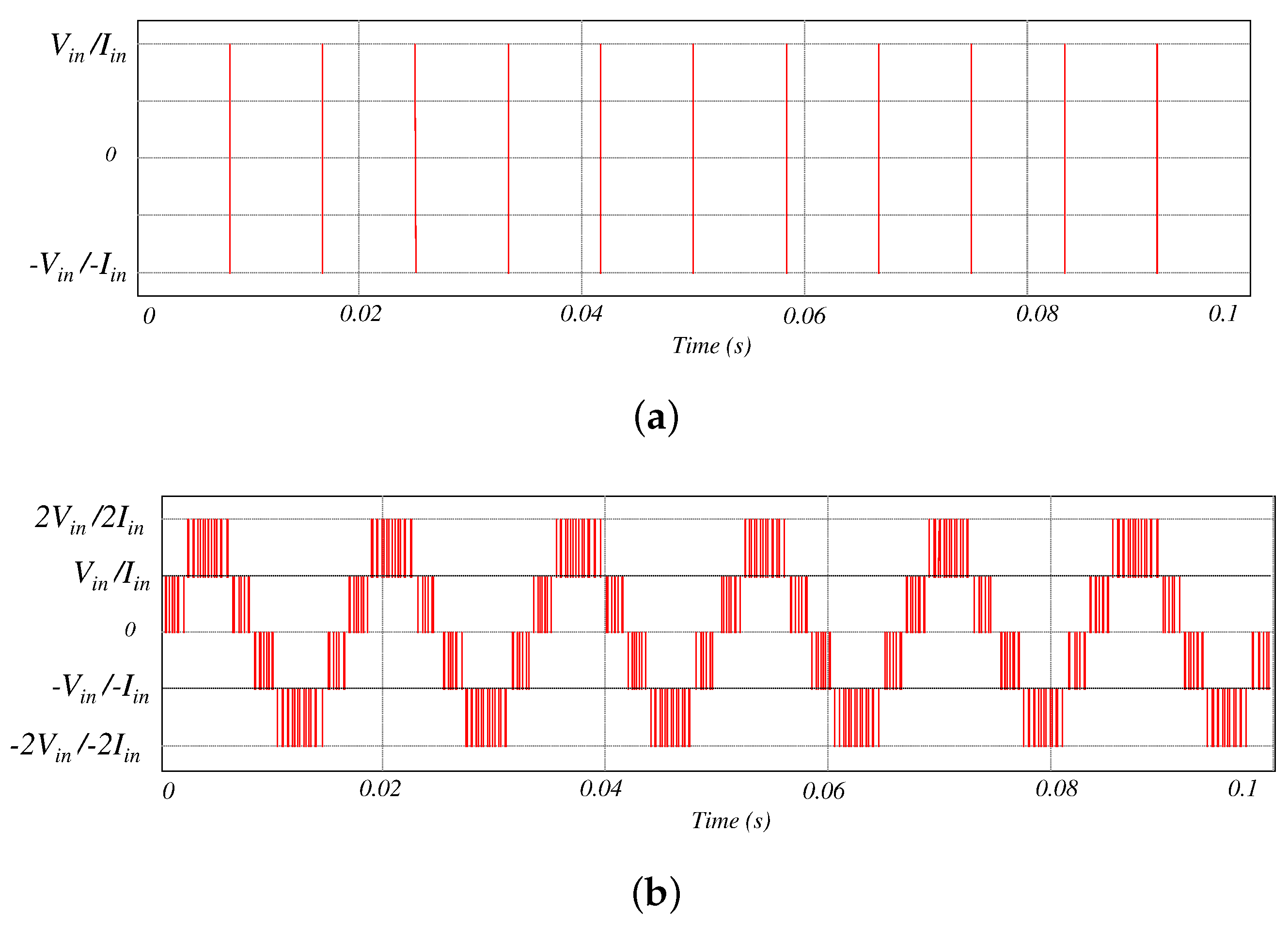
Figure 3 present a comparison between the output signal of traditional inverters and MLI. It is observed that the MLI shows a more sinusoidal waveform that traditional two level inverters, which allows obtaining the characteristics presented in
Table 2.
The development of MLI has been marked by the progress of semiconductor materials technology (IGBT, MOSFET, etc.) and the evident evolution of digital processors (microprocessors, DSP and FPGA). In this sense, in [
36], an interesting investigation is presented, and the most important conclusion could be that the use of 4H-SiC constitutes one of the most important aspects that enabled the current development of power converters. Hence, the multilevel inverters are rapidly emerging as a promising alternative in photovoltaic systems for high-power/medium-voltage DC/AC conversion. Within multilevel inverters, the Multilevel Voltage-Source Inverter (MVSI) inverter has got attention for a better quality power supply. In MVSI, the amplitude of the output voltage generally is less than the input, in these cases, the inverter behaves as a buck converter. Therefore, an intermediate boost stage is generally required since, in RES applications, the panel voltage is low. Nevertheless, by including this stage, the complexity of the system control increases, and the efficiency decreases.
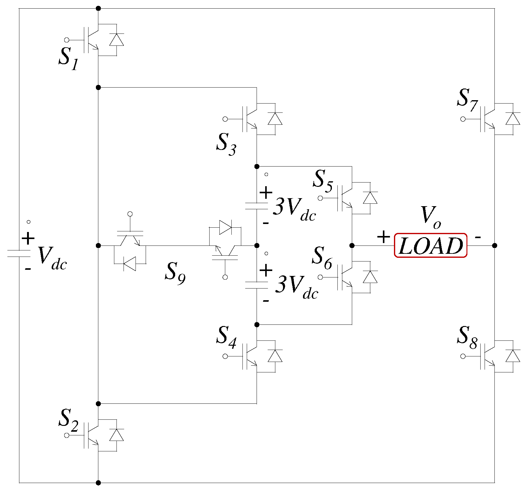
There is a close compromise between THD, inverter output levels and filter size. When the levels increases, THD and filter size decrease, but a higher number of components is required. Nowadays, an important challenge is to design schemes with a reduced number of components. Authors in [
37] introduce a novel topology, which seeks to reduce the number of switches as shown in
Figure 4. This scheme has three power supplies and ten semiconductors to deliver fifteen output levels.
The authors propose that the maximum output voltage by using this configuration is:
where:
is the input power supply and
is the output voltage in the load.
The document presented in [
38] summarizes the main schemes that make it possible to reduce the number of elements. The work concludes that the reduction of components causes the use of more expensive devices, by raising the voltage rating of semiconductor circuit breakers. Other aspects, such as the increase in the number of energy sources and more complex control schemes are also pointed out. The above approach shows the compromise that exists between the number of energy levels that the converter delivers and the complexity of its control, presenting a proportional relationship between both variables [
39].
The grid-connected PV systems must comply with certain standards such as VDE 0126-1-1, which regulates the maximum allowed of leakage current in the system. Leakage current flows when the terminals have high-frequency voltage transitions.This systems generally use transformers to ensure the isolation of the PV system. Hence, it is avoided the appearance of leakage current between the stray capacitances of the panel and the grid [
40], causing EMI problems, increased harmonic distortion and possible damage to health. The use of an isolation stage transformer increases as the weight, cost and volume of the system. In addition, this element causes losses in efficiency of around 3%. The newer topologies seek to eliminate this element. The main advantages are higher efficiency, adequate power density, and lower cost [
41]. Also, the performance of the control would be affected according to the winding settings [
42]. For this reason, transformerless PV inverters capture the interest of the scientific community [
43].
The European Network Code “Requirements for Generators” or VDE-AR-N 4105 is aimed at low voltage systems. The code establishes the grid connection standards for generation systems in Germany. The main parameters to monitor are the capabilities for frequency stabilization and the provision of reactive power. A comparative summary of the aforementioned standards is presented in
Table 3. In [
44], the principal regulations that the grid-connected systems must comply with are summarized.
3. Neutral Point Clamped Based Topologies
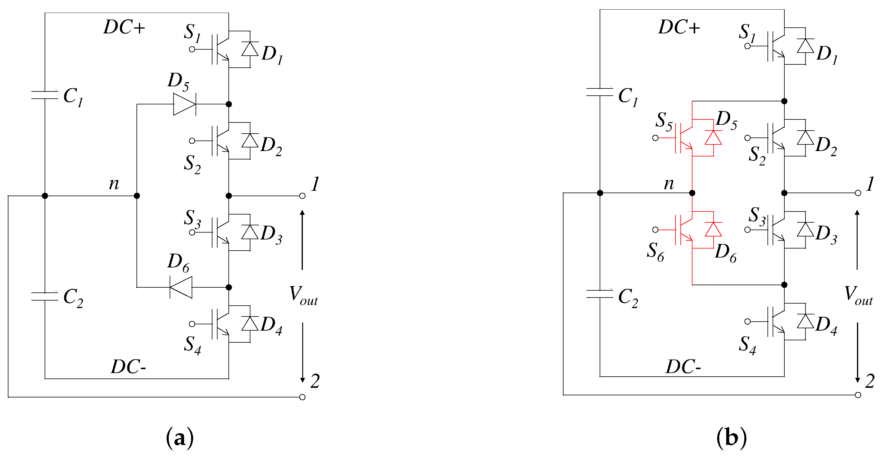
In NPC inverters, multiple DC sources are generated by dividing the input bus voltage using a capacitors bank as shown in
Figure 5a. The topology is recognized as one of the most popular schemes among MLI [
46].
Table 4 shows the allowed, potentially destructive, and destructive switching patterns that could be implemented in the basic structure of the Three-Level NPC (3L-NPC) inverters. The NPC converters are mainly employed in high and medium-power range [
47,
48]. This DC/AC converter have low dv/dt, low THD [
49] and can remove common-mode current making it attractive for PV applications [
50]. There are certain high-power applications in which NPC inverters allow a higher DC-link voltage and also avoid the series connection of semiconductors in the same branch [
51]. This devices have a large number of clamping diodes, unbalance problems in the DC-bus capacitors and a non-uniform distribution of losses in the switches. In standard operating conditions the values of the capacitors must have a value similar voltage. In [
52], a new PWM modulation strategy is proposed to control the output voltage and balance the DC bus capacitors for converters.
An alternative to the traditional NPC topology is the Active-NPC (ANPC) scheme. This variant arises to eliminate the previously mentioned disadvantages. In ANPC design, instead of using clamping diodes, bidirectional semiconductors are used, as shown in
Figure 5b. In both schemes (NPC and ANPC), it is possible to reduce the leakage current by connecting the middle point of the DC-bus to the grid ground. In this way, the value of
or
will depend on the sign of the output current. Therefore, the stray capacitance voltage remains constant and no leakage current arises. The conduction losses can be reduced by using different paths in the zero state. Currently, certain modifications of the traditional PWM have been implemented in ANPC topologies to achieve correct operation of the inverter, reducing conduction losses and achieving a correct balance of the capacitors.
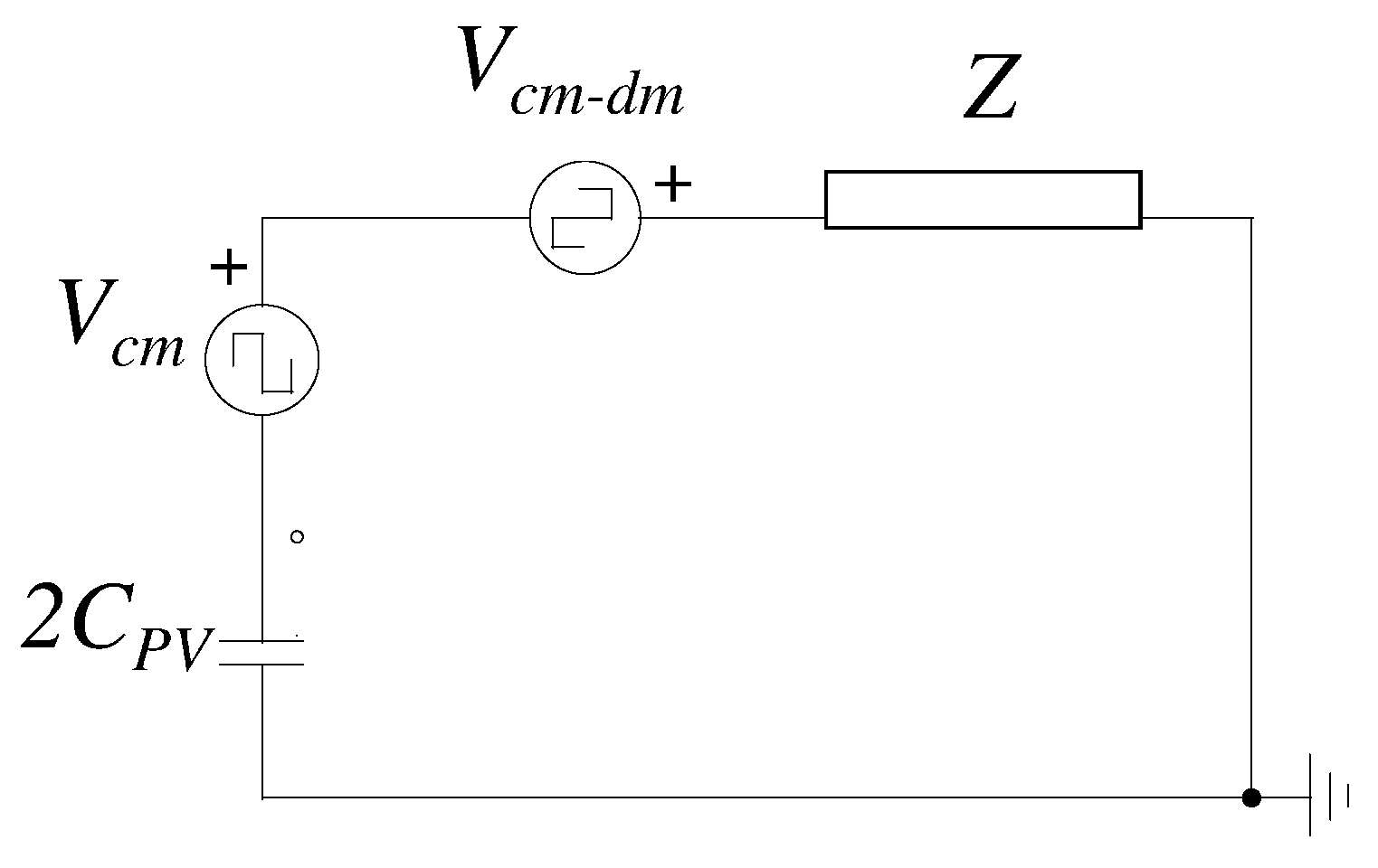
The techniques for eliminating the leakage current in PV inverters are grouped into two categories. The first introduces one switch to isolate the grid from the panels in freewheeling times. The second category maintains a neutral connection from the grid to the midpoint of the input capacitors and ensures low-voltage variations. Considering an NPC inverter, the common-mode voltage is defined from Equation (
2). From the mathematical point of view the reduction of the leakage current is achieved when there is no variation in the terms
and
.
Figure 6 shows a simplified electrical diagram, where the influence of the above terms in the emergence of leakage current is observed.
where: the common voltage and the differential voltage are defined as
and
, the voltage at the inverter output at (1) and (2) with respect to the neutral point (n) is defined as
and
respectively.
By considering Equations (
2) and (
3),
and
can be presented as:
where: the relationship between the common mode and the differential mode is determined by
.
The control strategy in this type of converter is divided into current loop based controllers and Direct Power Control (DPC). A good dynamic inverter response as well as a simple control scheme are two characteristics present in the DPC technique. The main disadvantage of this control strategy is the presence of a variable-switching frequency. Today this technique is combined with others such as Space Vector Modulation (SVM) [
53,
54] and MPC to achieve a fixed-switching frequency [
55,
56,
57,
58]. Control schemes should also include an appropriate modulation strategy, with particular emphasis on capacitor balancing. In this way, safe operation of the switches is achieved, avoiding over-voltage conditions.
Table 5 summarizes the works on the modulation techniques for NPC inverters. There are three factors that must be considered for the selection of the modulation strategy [
59]:
The redundant switching states.
The direction of the output current.
The influence on the instantaneous value of the capacitors.
Most of the methods [
68] that reduce the common-mode base their principle on selecting the vectors corresponding to Common-Mode Voltage (CMV) lower or zero without considering the oscillation of the neutral point voltage. In [
69], a novel virtual SVM where a zero NP current average and a low CMV in one control cycle is achieved. Martinez et al. in [
70], present a comparative analysis on different modulation techniques used in PV inverters. The results of the work throw certain conclusions that are interesting:
Phase Shifted-Pulse Width Modulation (PS-PWM) is a suitable solution for power filters, controlled rectifiers, etc., but this technique is not recommended for transformerless inverter applications.
Two-Sectors Hybrid-PWM (2SH-PWM) is easy to implement, reduces leakage ground current and is more efficient than 3L-PWM.
Six-Sectors Hybrid PWM (6SH-PWM) is capable of halving leakage ground current spikes compared to 2SH-PWM.
Three-Level PWM (3L-PWM), the 2SH-PWM, and the 6SH-PWM are three modulation strategies that achieve the correct operation of the transformerless grid-connected systems.
An analysis of the lifetime of inverters for photovoltaic applications is carried out in [
71], where an NPC based topology and a T-type inverter are compared. The authors conclude that inverters based on the NPC topology have a longer lifetime than T-type inverters. This conclusion exposes the durability and the use of this type of inverter in RES applications [
72,
73]. In this sense, authors in [
74] summarize a group of inverter topologies used in RE applications, highlighting the presence of a low leakage current in each of them. Ma et al. in [
72] propose a new PWM strategy for ANPC topologies, the scheme is illustrated in
Figure 7. The cited work present a modulation strategy based on an adjustable losses distribution that offers excellent performance and an increase the efficiency of the topology of the 97%. The switching pattern is presented in
Table 6.
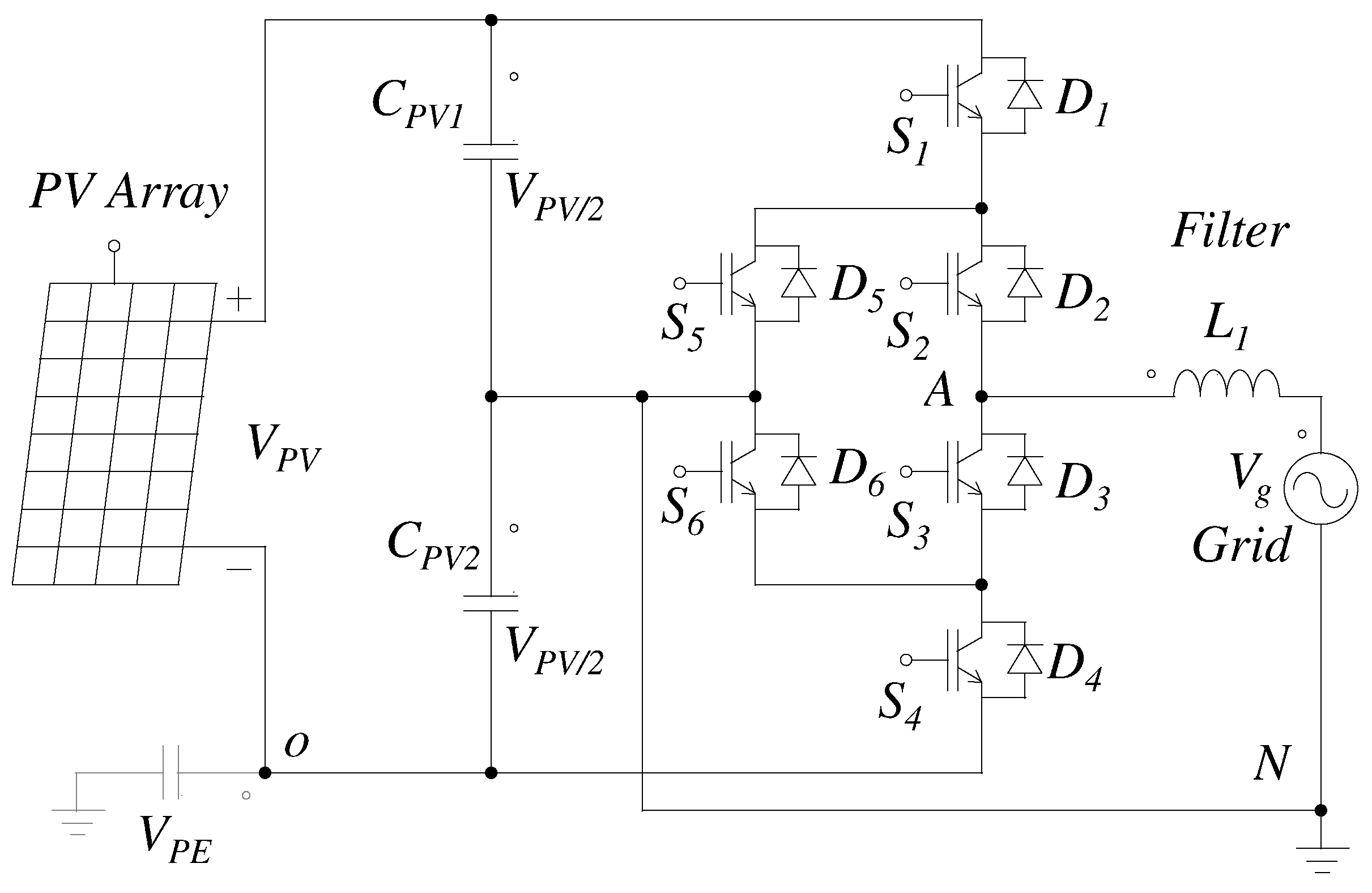
Wang et al. in [
75] propose a grid-connected 6S-5L-ANPC inverter. The topology reduces the number of switches since eight switches are generally used. This advantage reduces conduction and switching losses. An important comparison with traditional ANPC topologies considering the stress of semiconductor devices, the switching frequency, the switching losses, the conduction losses and the system volume is presented. In PV applications, special attention should be paid to THD. Therefore, the authors select the phase disposition PWM scheme as modulation strategy. This method directly affects the balance of flying capacitors. The proposal achieves a correct balance of the capacitors, also using a selection method to limit its voltage ripple.
Figure 8 present the aforementioned topology and
Table 7 shows the switching states of the inverter. In total, there are eight possible states. One of the most important results is a THD of 1.6%. The authors also present the equations for sizing capacitors in active and reactive power conditions. Equation (
7) establishes the capacitor value under the condition of unit power factor and Equation (
8) under reactive power condition.
where:
represents the line,
is the switching frequency frequency,
is the peak value of the output,
is the voltage drop,
is the electric charge, the modulation index is defined as
M and
N is the number of switching cycles.
4. Flying Capacitor Based Topologies
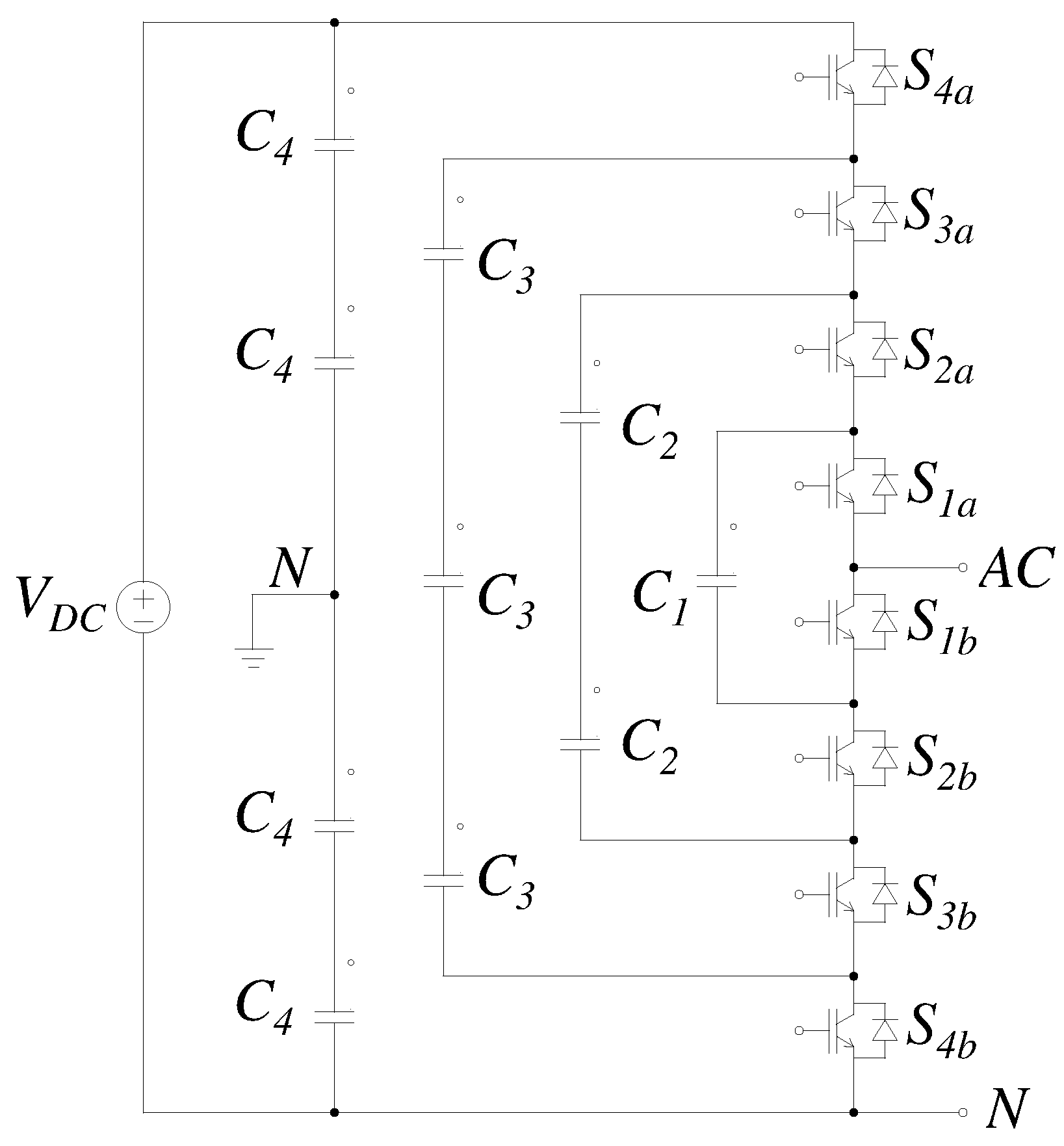
The FC concept was first introduced in 1992; this type of inverter uses different capacitors to deliver various levels of power at the converter output [
76]. The topology benefits include attractive properties in different power ranges, however they are more suitable for medium-voltage applications. Another advantage of topology is the possibility of using natural self-balancing. Furthermore, it has an equitable distribution of voltage stress between switches [
77]. Also, as in the case of NPC, a single source can be used to generate multiple voltage levels.In commercial applications, the use of FC with more than three output levels are more common than the NPC alternative [
78]. The presented topology is generally not used in PV applications. The scheme is more suitable for use in electric vehicles. However, it was decided to include it in work, since it is part of the most widely used voltage-source topologies.
Figure 9 illustrates a Five-Level FC (5L-FC) inverter and
Table 8 the operation modes are shown.
Despite the advantages mentioned, FC inverters have certain limitations that are addressed in current works. For example, capacitor banks reduce the life of the system, and sometimes the balance of floating capacitors can be complex [
79]. The problem of capacitor voltage balance is the main limitation of the use of the FC topology. Consequently, the scheme has not been generally used in PV applications. In the last decade, investigations related have been reported, for example, in [
80], using a
-
duty cycle mismatch measurement between two groups of Three-Level Flying Capacitor (3L-FC) topology switches to control the system without any additional detection.
Table 9 summarizes several works between the years 2015–2019.
In [
86] a novel converter is proposed, which has certain advantages, for example, reduced voltage stress on semiconductors, a wide voltage gain and a common grounded scheme. These characteristics can be commonly found in this type of inverter, however, FC-based converters are not generally used in RES, since they require a large number of input capacitors that increase the complexity of the techniques for balancing them [
87].
THD is reduced with more energy levels at the inverter output. In the case of FC, requires a large number of capacitors. A derivation of this configuration has been presented in [
88], where cross-connecting capacitors have achieved a higher voltage level at the output through additional switches.Another of the biggest challenges in this topology is to provide the necessary energy to activate the large number of switches that the scheme has. Ye et al. in [
89] present the comparison of five methods that reduce space and increase the efficiency of gate drive power supply circuits. Also, the operation of a multilevel FC inverter where an additional circuit is provided to avoid the defective cell, if it exists, is presented in [
90]. However, in this topology, the elements have to be oversized to operate at full-power level when the failure of one of the cells is detected.
The FC design must have several considerations. Various design methodologies are found in the bibliography. For example, authors in [
91] propose a methodology based on harmonic representation of the switching functions. The advantage of the proposed methodology lies in the possibility of being extrapolated to any FC-based scheme. Currently the uses of the treated scheme are very varied. There are certain applications in which a DC-bus is used due to voltage variations. Large capacitors are connected in parallel to the bus to avoid such voltage variations. Some of this applications are back-to-back converters, Power Factor Compensators (PFC), and uninterruptible power supply. The FC topology is chosen as the infinite virtual capacitor converter, which is a nonlinear capacitor where the voltage dependence of the load has a flat region and the voltage remains constant [
92].
5. Cascaded Based Topologies
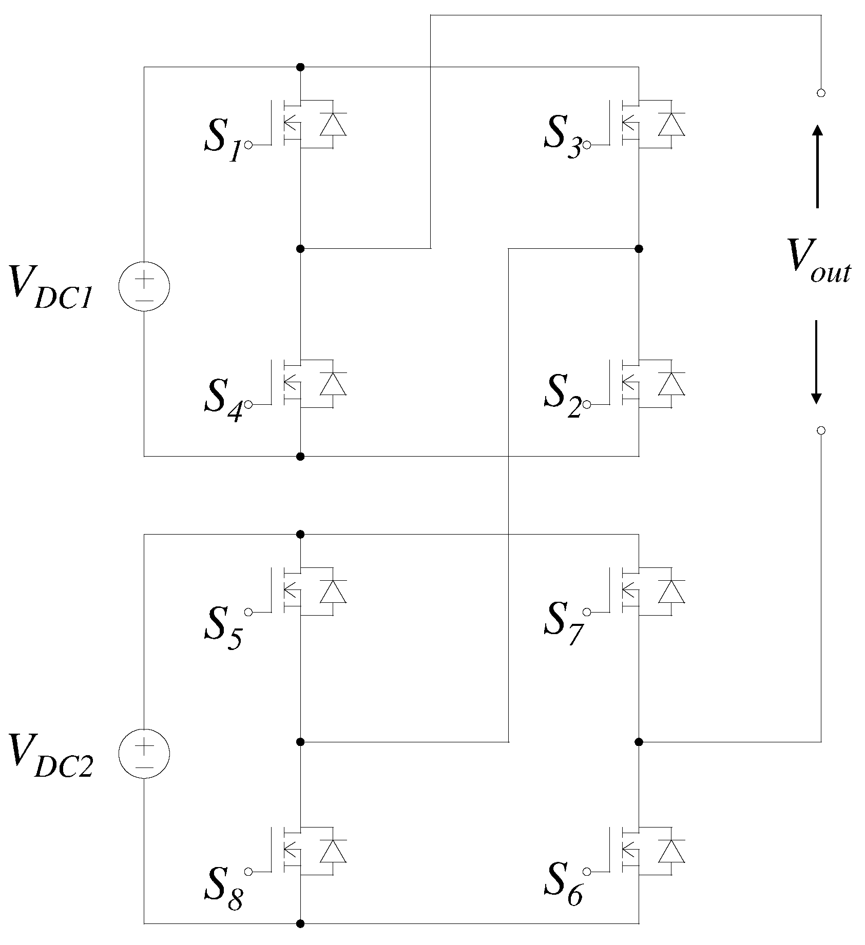
The CMLI integrates multiple H-bridge schemes to generate a multilevel voltage [
93]. The scheme has certain advantages compared to NPC and FC topologies, for example, they do not employ clamping diodes, in addition, a greater number of energy sources making it more suitable for specific applications such as electric vehicle [
94] and PV applications [
95]. Another advantage of the CMLI scheme is that, if any device fails in the bridge, the converter will continue to operate although it will deliver less energy. Therefore, this configuration is, to some extent, fault-tolerant. Also, its modularity and smaller filter size make it more attractive for high and medium-power PV applications.
Figure 10 present a basic configuration of the CMLI topology, and
Table 10 shows the switching pattern for the five output levels.
Despite the aforementioned advantages, the topology has certain limitations. The main disadvantage is the use of isolated DC sources for each H-bridge. This problem was solved in the FC and NPC topology, but the voltage adjustment of the capacitors is complex [
96]. Also, during partial shading the energy captured by the system is reduced. In certain investigations have presented various studies about the partial shading of PV modules, but most of the schemes are complex designs that generally cause a decrease in the efficiency of the system and an increase in the cost of the inverter [
97,
98].
The selection of the controller in CMLI depends on the topology and the application. Each controller has favorable characteristics in certain systems, ranging from less complexity to a desired dynamic response. Various types of controllers are used with the scheme discussed. The most widely used are PR controller and PI. When used LC or LCL filters using traditional controllers such as PI is not appropriate because it does not completely eliminate the steady state error [
99]. Control systems that employ proportional-resonant controllers eliminate steady-state error. These controllers provide infinite gain in resonance frequency. Equation (
9) defines the ideal PR control. In [
100] a new technique to synchronize MLI with the grid using PR controller is shown. In the presented design, the control scheme has a lower error between the real power and the reference compared to the PI controller.
where:
is the fundamental frequency (grid frequency),
and
represent proportional and resonant gains respectively.
Grid-connected systems can be classified according to the Maximum Power Point Tracking (MPPT) method used. The two classifications are centralized or distributed. The distributed technique reports better efficiency in the literature, but is more complex and has a larger volume than the centralized MPPT methods [
101]. In the case of cascade inverters, the implementation of a distributed method requires a large number of sensors and considerably increases the cost of the system.
Figure 11 illustrates the most common architectures in the distributed MPPT method. In micro-inverters of the
Figure 11a, the energy generated by the different modules is injected directly into the grid. In front-end DC optimizers presented in
Figure 11b, the converters perform the MPPT separately. Its output is connected in series; thus, the power that is injected into the grid is the sum of each module. If a module has low efficiency, it does not affect the rest of the converters, since each module provides its power separately.
Authors in [
102] present a low cost and straightforward distributed MPPT method for energy optimizers in CMLI-based photovoltaic systems using front-end DC optimizers. In [
103] a simplified feedforward distributed MPPT method for grid-connected CMLI is presented. The authors use the method as a
“… superior solution for PV system grid integration due to its simple implementation, signal stage power conversion, no added complexity with increasing the number of connected modules, and it eliminates the need for individual control loop for each module…” It is important to mention that most conventional techniques do not achieve a distributed MPPT, which decreases the efficiency of the system. Goetz et al. in [
104] propose a modular Double Cascading H-bridge
topology. The scheme reduces the output of the inverter filter and achieves a fast dynamic response. The MPPT is carried out in each module, which incorporates a battery for energy storage. The use of batteries in PV applications is avoided since these elements are highly polluting, then they break with the concept of clean energy. One of the essential advantages of the topology is the possibility of being extended to
circuits in general.
A brief bibliographic review shows the use of topology as a fault-tolerance scheme. In photovoltaic applications, faults distort the output voltage, degrading the power supplied. A fault diagnosis scheme must detect the problem in the shortest possible time to avoid serious failures in the system, and each design requires its strategy. A common problem is considering that the system is in open circuit to monitor its status [
105]. Shao et al. in [
106], present a technique for detecting faults using Sliding Mode Observer (SMO) able to locate the fault element in the system. The authors in [
107] present a detailed review of various faults in photovoltaic systems. The work identifies the main faults as line-line, earth, arc, shadow and others, and proposes its protection strategy. Various strategies are employed for fault detection in PV systems, using standard protection devices or offline/real-time testing of PV systems.
Table 11 shows a summary of typical failure cases and respective protection/detection devices.
Currently, there is a trend towards the combined use of PV energy and batteries as a storage medium and certain studies analyze its feasibility. For example, authors in [
108] conducts extensive research concluded in 2019, in Finland. The work considers the profitability of BESS investments between the years 2018 and 2035. The authors conclude that, these systems would not be profitable for RES applications at present, although a decrease in costs is estimated from 1270 to 1370 euros/kWh in 2018 to 830–930 euros/kWh in 2035. However, sometimes an uninterrupted flow of energy is required and the use of batteries is essential due to PV power intermittent nature. The BESS output is controllable and the system can be treated as a controllable load [
109].
The grid-connected schemes in this typology, as in the previous ones, still have certain challenges. Decreasing the leakage current in transformerless systems is one of the main aspects to consider. In this regard, some research has been carried out, such as [
110]. In this work an analysis of the behavior of the leakage current of the different modes of operation of the basic structure CMLI is presented. The analysis considers the common-mode inductor in each switching state and can be simpler if pole voltages are used. Also, the authors propose two schemes of suppression of the leakage current. The first solution uses low-capacitance common-mode capacitors and stray capacitors as part of the output filter. It is included that this solution is suitable for inverters operated at high-frequencies. Solution two is appropriate when the converter uses a switching frequency of less than 1.5 kHz.
Sonti et al. in [
111] present a PWM technique to eliminate or reduce leakage current in CMLI-based schemes. The work integrates the applied MPPT and PWM algorithm. In this way, it is possible to reduce the high-frequency transitions of voltage and the CMV.
Figure 12 shows the proposed architecture and
Table 12 present the switching states. The switches
,
and
,
operate in a complementary way. Hence, there are three pairs of switches [
,
,
], [
,
] and [
,
]. Modulation proposal isolates PV array and grid during freewheeling states, operating similarly to an H5 topology. The authors achieve leakage current reduction with the presence of low-frequency transitions in the PV terminal voltage.
6. Comparative Study
The section present a comparative table between NPC and CMLI schemes. As mentioned above, at present, FC-based topology is not generally used in PV applications. The comparison takes into account different aspects such as input voltage value, switching frequency, control strategy, efficiency and leakage current and only includes recent works. Other recent works establish different comparisons according to the topic they address. The authors in [
112] show five control methods based on SMC, the comparison is made considering the topology, the modes of operation and the number of sensors required. Lee in [
113], establishes a comparative analysis of recent topologies based on cascade inverters, which reveals that the
proposed in the document achieves the reduction of the switch count.
It can be appreciated that the switching frequencies rarely exceed 15 kHz. Increasing the switching speed causes an increase in the system losses and the THD. There is a compromise between the number of output levels and the speed of the switches. Increasing the number of power levels imply slower switching frequency.
All the works presented comply with the two most important grid connection standards. These standards establish a maximum leakage current and THD of 300 mA and 5%, respectively. Compliance with standards largely depends on the strategy of modulation employed. From the data presented, it is observed that the SVPWM technique and its variants are the most recurrent when it is required to decrease the voltage in common-mode topologies.
Another element that is noted is the use of inverters with 3 output levels. The authors note a compromise between the number of levels and the number of elements in their topology. Generally, with 3 levels, satisfactory results are obtained, as showed in
Table 13.


