A Comprehensive Survey on Phasor Measurement Unit Applications in Distribution Systems


Abstract
1. Introduction
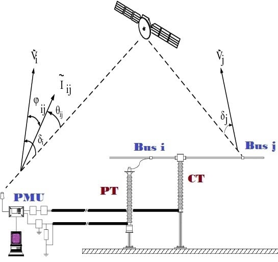
2. PMU
2.1. PMU Performance Evaluation
- Availability means that data measured by the PMU can be sent to the PDC in a timely manner.
- Reliability is the strength and sufficient connectivity of the network for a prescribed performance level. A reliable and universal communication infrastructure is a crucial challenge in both the structure and the operation of WAMS communication systems.
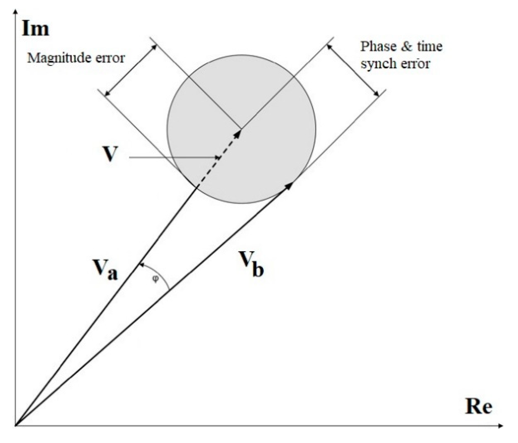
- Accuracy is the difference between the measured value and the actual value. An accuracy index is using for the magnitude and angle, which is called the total vector error (TVE). The PMU performance standards refer to a 1% TVE [22]. However, this is changing based on PMU applications. TVE can be calculated bywhere is the true synchrophasor and is the synchrophasor estimated by the PMU. The subscripts and indicate the real and imaginary parts of the synchrophasor, respectively. In Figure 3, which represents a TVE, is the true phasor that should be measured, is the measured phasor with the magnitude error, and is the measured phasor with the phase and time synch error. Amplitude errors, phase errors, and synchronization accuracy are important factors influencing the TVE value.
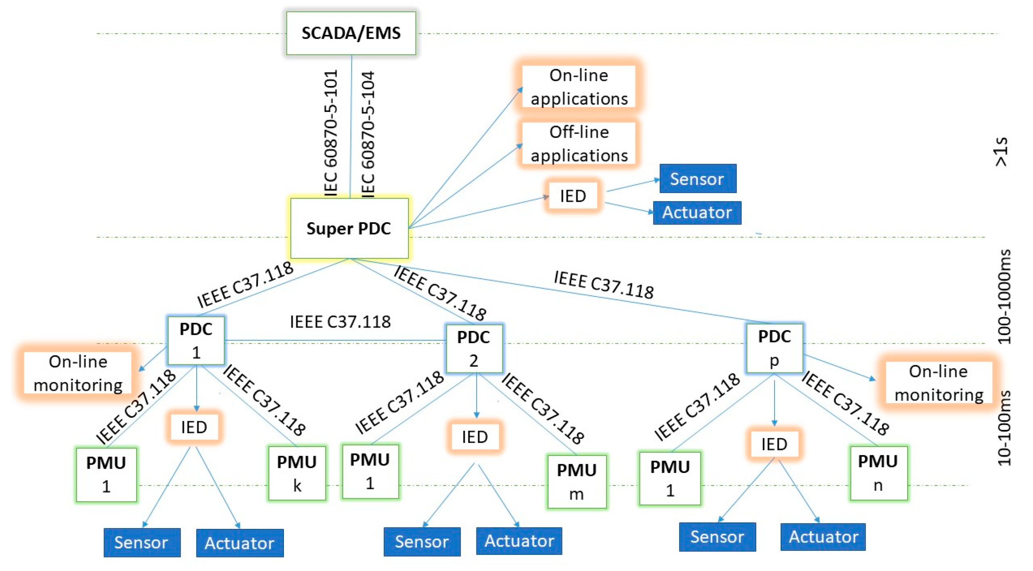
- The latency or the time delay in a network is the time taken to transfer data from one point to another point. The WAMS latency stages are shown in Figure 5.
- Message rate/resolution: A PMU takes many rapid physical measurements (samples) of voltage and/or current, computes phasor quantities from these samples, and then time-stamps and reports the phasor for each cycle or two cycles. Measured synchrophasors should be reported by a reporting rate, , frequently [31]. The reporting rate is expressed in frames per second.
- Data loss: A PMU’s data loss may occur due to GPS signal loss or communication network congestion. Generally, PDCs collect PMUs data based on the time stamp of the data stream. They also have a time-out function. Therefore, PMU data that does not arrive within a specified time will be dropped [32]. Based on the results of [33], most of the GPS loss events recover within a short period.
2.2. Communication
3. PMU Applications in Distribution Systems
3.1. Power System Automation (Class A)
3.1.1. Microgrid Operation
3.1.2. Fault Detection and Location
3.1.3. FACTS Devices
3.2. Power System Reliability/Coordination (Class B)
Situational Awareness
3.3. Power System Planning (Class C)
3.3.1. State Estimation (SE)
3.3.2. Voltage Stability
3.3.3. Power Quality Analysis
- voltage interruption;
- voltage disturbances, such as voltage sag/swell, transient, impulse, etc;
- waveform quality problems, such as magnitude, imbalance, harmonics, flicker, etc.
3.3.4. DG Characterization
- Increases in short circuit levels;
- Changes to voltage profiles;
- Congestions in system branches;
- Power quality and reliability issues; and
- Malfunctioning power grid protections.
- Reversed power flow detection;
- Feeder voltage coordination based on DG behavior; and
- Disaggregate net metered DG from load.
3.3.5. Model Validation
3.4. Power System Operation (Class D)
3.4.1. Topology and Disturbance Detection
3.4.2. Phase Identification
4. PMU Deployment
5. Conclusions
Author Contributions
Funding
Conflicts of Interest
Abbreviations
| AMI | Automated Metering Infrastructure |
| BB | Broadband |
| CAPEX | Capital Expenses |
| UTC | Coordinated Universal Time |
| CT | Current Transformer |
| DER | Distributed Energy Resources |
| DFR | Data Fault Recorder |
| DG | Distributed Generator |
| D-FACTS | Distributed FACTS |
| DME | Disturbance Monitoring Equipment |
| DSE | Dynamic SE |
| EMS | Energy Management System |
| eMBB | Enhanced Mobile Broadband |
| EVs | Electric Vehicles |
| FACTS | Flexible AC Transmission System |
| FL | Fault Location |
| GPS | Global Positioning System |
| GMA | Grid Monitoring and Automation |
| HVDC | High-voltage Direct Current |
| IoT | Internet of Things |
| LCOE | Levelized Cost of Electricity |
| IED | Intelligent Electronic Device |
| LFC | Load Frequency Control |
| LTE | Long-Term Evolution |
| LV | Low Voltage |
| MMG | Maritime Microgrid |
| mMTC | Machine-Type Communications |
| MTC | Mission- and Time-Critical |
| MV | Medium Voltage |
| NB | Narrowband |
| NAPSI | North American Synchrophasor Initiative |
| OPEX | Operational Expenses |
| PDC | Phasor Data Concentrator |
| PMU | Phasor Measurement Unit |
| PT | Potential Transformer |
| PLC | Power Line Communication |
| PLUS | Power Line data bUS |
| PSL | Power Standards Lab |
| PS | Primary Substation |
| QoS | Quality of Service |
| OPP | Optimal PMU Placement |
| ROCOF | Rate of Change of Frequency |
| RTU | Remote Terminal Unit |
| RER | Renewable Energy Resources |
| SEL | Schweitzer Engineering Laboratories |
| SE | State Estimation |
| SSE | Static SE |
| SCADA | Supervisory Control and Data Acquisition |
| TVE | Total Vector Error |
| URLLC | Ultra-Reliability Low-Latency Communications |
| WAMS | Wide-Area Monitoring System |
References
- Oettinger, G.H. Energy Roadmap 2050; Publications Office of the European Union: Brussels, Belgium, 2011. [Google Scholar] [CrossRef]
- Jordehi, A.R. How to Deal with Uncertainties in Electric Power Systems? A Review. Renew. Sustain. Energy Rev. 2018, 96, 145–155. [Google Scholar] [CrossRef]
- Hirth, L. The Market Value of Variable Renewables. The Effect of Solar Wind Power Variability on Their Relative Price. Energy Econ. 2013, 38, 218–236. [Google Scholar] [CrossRef]
- Edenhofer, O.; Hirth, L.; Knopf, B.; Pahle, M.; Schlömer, S.; Schmid, E.; Ueckerdt, F. On the Economics of Renewable Energy Sources. Energy Econ. 2013, 40, 12–23. [Google Scholar] [CrossRef]
- Ueckerdt, F.; Hirth, L.; Luderer, G.; Edenhofer, O. System LCOE: What Are the Costs of Variable Renewables? Energy 2013, 63, 61–75. [Google Scholar] [CrossRef]
- Akrami, A.; Doostizadeh, M.; Aminifar, F. Power System Flexibility: An Overview of Emergence to Evolution. J. Mod. Power Syst. Clean Energy 2019, 7, 987–1007. [Google Scholar] [CrossRef]
- Negnevitsky, M. High Renewable Energy Penetration and Power System Security: New Challenges and Opportunities. In Proceedings of the 10th International Scientific Symposium on Electrical Power Engineering ELEKTROENERGETIKA, Stará Lesná, Slovakia, 16–18 September 2019; pp. 16–25. [Google Scholar]
- Colmenar-Santos, A.; Campíñez-Romero, S.; Pérez-Molina, C.; Castro-Gil, M. Profitability Analysis of Grid-Connected Photovoltaic Facilities for Household Electricity Self-Sufficiency. Energy Policy 2012, 51, 749–764. [Google Scholar] [CrossRef]
- Lai, C.S.; McCulloch, M.D. Levelized Cost of Electricity for Solar Photovoltaic and Electrical Energy Storage. Appl. Energy 2017, 190, 191–203. [Google Scholar] [CrossRef]
- Gómez, A.; Dopazo, C.; Fueyo, N. The “Cost of Not Doing” Energy Planning: The Spanish Energy Bubble. Energy 2016, 101, 434–446. [Google Scholar] [CrossRef]
- Byrne, R.H.; Trudnowski, D.J.; Neely, J.C.; Elliott, R.T.; Schoenwald, D.A.; Donnelly, M.K. Optimal Locations for Energy Storage Damping Systems in the Western North American Interconnect. In Proceedings of the IEEE PES General Meeting Conference & Exposition, National Harbor, MD, USA, 27–31 July 2014; pp. 1–5. [Google Scholar] [CrossRef]
- Power System Engineering, Inc. Available online: https://www.powersystem.org/scada (accessed on 28 November 2019).
- Liu, Y.; You, S.; Yao, W.; Cui, Y.; Wu, L.; Zhou, D.; Zhao, J.; Liu, H.; Liu, Y. A Distribution Level Wide Area Monitoring System for the Electric Power Grid-FNET/GridEye. IEEE Access 2017, 5, 2329–2338. [Google Scholar] [CrossRef]
- Aminifar, F.; Khodaei, A.; Fotuhi-Firuzabad, M.; Shahidehpour, M. Contingency-Constrained PMU Placement in Power Networks. IEEE Trans. Power Syst. 2010, 25, 516–523. [Google Scholar] [CrossRef]
- Akhlaghi, S. Optimal PMU Placement Considering Contingency-Constraints for Power System Observability and Measurement Redundancy. In Proceedings of the 2016 IEEE Power and Energy Conference at Illinois (PECI), Urbana, IL, USA, 19–20 February 2016; pp. 1–7. [Google Scholar] [CrossRef]
- Akhlaghi, S.; Zhou, N.; Wu, N.E. PMU Placement for State Estimation Considering Measurement Redundancy and Controlled Islanding. In Proceedings of the 2016 IEEE Power and Energy Society General Meeting (PESGM), Boston, MA, USA, 17–21 July 2016; pp. 1–5. [Google Scholar] [CrossRef]
- Xie, N.; Torelli, F.; Bompard, E.; Vaccaro, A. A Graph Theory Based Methodology for Optimal PMUs Placement and Multiarea Power System State Estimation. Electr. Power Syst. Res. 2015, 119, 25–33. [Google Scholar] [CrossRef]
- Sarailoo, M.; Wu, N.E. A New PMU Placement Algorithm to Meet a Specified Synchrophasor Availability. In Proceedings of the 2016 IEEE Power & Energy Society Innovative Smart Grid Technologies Conference (ISGT), Minneapolis, MN, USA, 6–9 September 2016; pp. 1–5. [Google Scholar] [CrossRef]
- Li, Q.; Cui, T.; Weng, Y.; Negi, R.; Franchetti, F.; Ilic, M.D. An Information-Theoretic Approach to PMU Placement in Electric Power Systems. IEEE Trans. Smart Grid 2013, 4, 446–456. [Google Scholar] [CrossRef]
- Zhang, C.; Jia, Y.; Xu, Z.; Lai, L.L.; Wong, K.P. Optimal PMU Placement Considering State Estimation Uncertainty and Voltage Controllability. IET Gener. Transm. Distrib. 2017, 11, 4465–4475. [Google Scholar] [CrossRef]
- Miron, S. From SCADA to smart grid in power transmission and distribution systems. Bul. AGIR 2011, 4, 191–198. [Google Scholar]
- IEEE Standard for Synchrophasor Measurements for Power Systems; IEEE: Piscataway, NJ, USA, 2011.
- IEEE Standard for Synchrophasor Measurements for Power Systems—Amendment 1: Modification of Selected Performance Requirements; IEEE Std. C37.118.1a-2014 (Amendment to IEEE Std C37.118.1-2011); IEEE: Piscataway, NJ, USA, 2014; pp. 1–25. [CrossRef]
- Simens. Phasor Measurement Unit (PMU) and Grid Monitoring. Available online: https://w3.siemens.com/smartgrid/global/en/products-systems-solutions/protection/pmu-phasor-measurment-unit/pages/pmu-phasor-measurement-unit.aspx (accessed on 28 November 2019).
- Singh, B.; Sharma, N.; Tiwari, A.; Verma, K.; Singh, S. Applications of phasor measurement units (PMUs) in electric power system networks incorporated with FACTS controllers. Int. J. Eng. Sci. Technol. 2011, 3, 64–82. [Google Scholar] [CrossRef]
- Galleon Sysmtems. Available online: https://www.atomic-clock.galleon.eu.com/support/gps-time-accuracy.html (accessed on 28 November 2019).
- Mina, T.Y.; Bhamidipati, S.; Gao, G.X. Detecting GPS spoofing via a multi-receiver hybrid communication network for power grid timing verification. In Proceedings of the 31st International Technical Meeting of the Satellite Division of The Institute of Navigation (ION GNSS+ 2018), Hyatt Regency Miami, FL, USA, 24–28 September 2018; pp. 2963–2977. [Google Scholar] [CrossRef]
- Mini, S.T.; McDonald, J.D. Power System SCADA and Smart Grids, 1st ed.; CRC Press: Boca Raton, FL, USA, 2015. [Google Scholar]
- Sundararajan, A.; Khan, T.; Moghadasi, A.; Sarwat, A.I. A survey on synchrophasor data quality and cybersecurity challenges, and evaluation of their interdependencies. J. Mod. Power Syst. Clean Energy 2018, 7, 1–18. [Google Scholar] [CrossRef]
- Lira, R.; Mycock, C.; Wilson, D.; Kang, H. PMU Performance Requirements and Validation for Closed Loop Applications. In Proceedings of the 2011 2nd IEEE PES International Conference and Exhibition on Innovative Smart Grid Technologies, Manchester, UK, 5–7 December 2011; pp. 1–7. [Google Scholar] [CrossRef]
- Miller, L.E.; Silverstein, A.; Anand, D.; Goldstein, A.; Makarov, Y.; Tuffner, F.; Jones, K. PMU Data Quality: A Framework for the Attributes of PMU Data Quality and a Methodology for Examining Data Quality Impacts to Synchrophasor Applications; NASPI: Washington, DC, USA, 2017; pp. 1–77. [Google Scholar]
- Chakrabortty, A.; Ilić, M.D. Control and Optimization Methods for Electric Smart Grids, 1st ed.; Ilic, M.D., Ed.; Springer: Berlin, Germany, 2012. [Google Scholar] [CrossRef]
- Huang, C.; Li, F.; Zhou, D.; Guo, J.; Pan, Z.; Liu, Y.; Liu, Y. Data quality issues for Synchrophasor applications Part I: A review. J. Mod. Power Syst. Clean Energy 2016, 4, 342–352. [Google Scholar] [CrossRef]
- Arghira, N.; Hossu, D.; Făgărăşan, I.; Iliescu, S.S.; Costianu, D.R. Modern scada philosophy in power system operation—A survey. UPB Sci. Bull. Ser. C Electr. Eng. 2011, 73, 153–166. [Google Scholar]
- Siow, L.K.; So, P.L.; Gooi, H.B.; Luo, F.L.; Gajanayake, C.J.; Vo, Q.N. Wi-Fi Based Server in Microgrid Energy Management System. In Proceedings of the TENCON 2009–2009 IEEE Region 10 Conference, Singapore, 23–26 January 2009; pp. 1–5. [Google Scholar] [CrossRef]
- Eissa, M.M. New Protection Principle for Smart Grid with Renewable Energy Sources Integration Using WiMAX Centralized Scheduling Technology. Int. J. Electr. Power Energy Syst 2018, 97, 372–384. [Google Scholar] [CrossRef]
- Batista, N.C.; Melício, R.; Matias, J.C.O.; Catalão, J.P.S. Photovoltaic and Wind Energy Systems Monitoring and Building/Home Energy Management Using ZigBee Devices within a Smart Grid. Energy 2013, 49, 306–315. [Google Scholar] [CrossRef]
- Castello, P.; Ferrari, P.; Flammini, A.; Muscas, C.; Pegoraro, P.A.; Rinaldi, S. A distributed PMU for electrical substations with wireless redundant process bus. IEEE Trans. Instrum. Meas. 2015, 64, 1149–1157. [Google Scholar] [CrossRef]
- Ali, J.; Ahmed, U.; Farhan, M. Framework for Implementation of AGA 12 for Secured SCADA Operation in Oil and Gas Industry. In Proceedings of the 2015 2nd International Conference on Computing for Sustainable Global Development (INDIACom), New Delhi, India, 11–13 March 2015. [Google Scholar] [CrossRef]
- Chenine, M.; Nordstrom, L. Modeling and simulation of wide-area communication for centralized PMU-based applications. IEEE Trans. Power Deliv. 2011, 26, 1372–1380. [Google Scholar] [CrossRef]
- Chin, W.L.; Li, W.; Chen, H.H. Energy big data security threats in IoT-based smart grid communications. IEEE Commun. Mag. 2017, 55, 70–75. [Google Scholar] [CrossRef]
- Katsaros, K.V.; Yang, B.; Chai, W.K.; Pavlou, G. Low Latency Communication Infrastructure for Synchrophasor Applications in Distribution Networks. In Proceedings of the IEEE International Conference on Smart Grid Communication, Venice, Italy, 3–6 November 2014. [Google Scholar] [CrossRef]
- Kumar, S.; Soni, S.K.; Jain, D.K. Requirements and challenges of PMUs communication in WAMS environment requirements and challenges of PMUS communication in WAMS enviroment. Far East J. Electron. Commun. 2014, 13, 121–135. [Google Scholar]
- Unsal, D.B.; Yalcinoz, T. Applications of new power line communication model for smart grids. Int. J. Comput. Electr. Eng. 2015, 7, 168–178. [Google Scholar] [CrossRef]
- Dostert, K. Powerline Communications; Prentice Hall: Upper Saddle River, NJ, USA, 2001. [Google Scholar]
- Lampe, L.; Andrea, T.T.; Swart, G. (Eds.) Power Line Communications: Principles, Standards and Applications from Multimedia to Smart Grid, 2nd ed.; John Wiley & Sons: Hoboken, NJ, USA, 2016. [Google Scholar] [CrossRef]
- Dominiak, S.; Dersch, U. Precise Time Synchronization of Phasor Measurement Units with Broadband Power Line Communications; Swiss Federal Office of Energy SFOE: Bern, Switaerland, 2017. [Google Scholar]
- Benato, R.; Caldon, R. Application of PLC for the control and the protection of future distribution networks. In Proceedings of the IEEE International Symposium on Power Line Communications and Its Applications, Pisa, Italy, 26–28 March 2007; pp. 499–504. [Google Scholar] [CrossRef]
- Dersch, U. PLUS (Power Line Data BUS ) Based Avionics Data Bus Power PLUS Data over the Same Aircraft Wiring-Reducing Its Weight, Volume and Complexity P Ower L Ine Data B US PLUS Protocol & Technology Platform; PLUS: Amstelveen, The Netherlands, 2016. [Google Scholar]
- Thomas Heuzeroth. Die Ganze Wahrheit Über die Nächste Mobilfunk-Generation. Available online: https://www.welt.de/wirtschaft/webwelt/article189459047/5G-Die-ganze-Wahrheit-ueber-die-naechste-Mobilfunk-Generation.html (accessed on 28 November 2019).
- Popovski, P.; Trillingsgaard, K.; Osvaldo, S.; Durisi, G. 5G Wireless Network Slicing for EMBB, URLLC, and MMTC: A Communication-Theoretic View. IEEE Access 2018, 6, 55765–55779. [Google Scholar] [CrossRef]
- Cosovic, M.; Tsitsimelis, A.; Vukobratovic, D.; Matamoros, J.; Anton-Haro, C. 5G Mobile Cellular Networks: Enabling Distributed State Estimation for Smart Grids. IEEE Commun. Mag. 2017, 55, 62–69. [Google Scholar] [CrossRef]
- Rana, M.; Li, L.; Su, S. Kalman Filter Based Microgrid State Estimation and Control Using the IoT with 5G Networks. In Proceedings of the IEEE PES Asia-Pacific Power and Energy Engineering Conference (APPEEC), Brisbane, QLD, Australia, 15–18 November 2015. [Google Scholar] [CrossRef]
- Gheisarnejad, M.; Khooban, M.-H.; Dragicevic, T. The Future 5G Network Based Secondary Load Frequency Control in Maritime Microgrids. IEEE J. Emerg. Sel. Top. Power Electron. 2019, 1–8. [Google Scholar] [CrossRef]
- DotEcon Ltd. Axon Partners. In Study on Implications of 5G Deployment on Future Business Models Axon Partners Group; DotEcon Ltd.: Lundon, UK, 2018. [Google Scholar]
- 5G Americas White Paper. 5G The Future of IoT. Available online: https://www.5gamericas:5g-the-future-of-iot/ (accessed on 28 November 2019).
- Smart Grids Infrastructure, Technology, and Solutions, 1st ed.; Stuart, B., Ed.; Taylor & Francis: Lundon, UK, 2013. [Google Scholar] [CrossRef]
- Martínez, C.; Parashar, M.; Dyer, J.; y Coroas, J. Real time monitoring, control and protection. Phasor data requirements for real time wide-area monitoring, control and protection applications. Consort. Electr. Reliab. Technol. Solut. 2005, 26, 8. [Google Scholar]
- KTH(SE). Distribution Network Dynamics Monitoring, Control, and Protection Solutions Including Their Interface to TSOs; KTH Royal Institute of Technology: Stockholm, Sweden, 2015. [Google Scholar]
- Kong, X.; Chen, Y.; Xu, T.; Wang, C.; Yong, C.; Li, P.; Yu, L. A hybrid state estimator based on SCADA and PMU measurements for medium voltage distribution system. Appl. Sci. 2018, 8, 1527. [Google Scholar] [CrossRef]
- Kansal, P.; Bose, A. Bandwidth and latency requirements for smart transmission grid applications. IEEE Trans. Smart Grid 2012, 3, 1344–1352. [Google Scholar] [CrossRef]
- Von Meier, A.; Culler, D.; McEachern, A.; Arghandeh, R. Micro-Synchrophasors for distribution systems. In Proceedings of the IEEE PES Innovative Smart Grid Technologies Conference (ISGT), Washington, DC, USA, 19–22 February 2014; pp. 1–5. [Google Scholar] [CrossRef]
- Bag, G.; Thrybom, L.; Hovila, P. Challenges and Opportunities of 5G in Power Grids. CIRED Open Access Proc. J. 2017, 2017, 2145–2148. [Google Scholar] [CrossRef]
- Almas, M.S.; Vanfretti, L. RT-HIL Implementation of the hybrid Synchrophasor and GOOSE-based passive islanding schemes. IEEE Trans. Power Deliv. 2016, 31, 1299–1309. [Google Scholar] [CrossRef]
- Usman, M.U.; Faruque, M.O. Applications of synchrophasor technologies in power systems. J. Mod. Power Syst. Clean Energy 2019, 7, 211–226. [Google Scholar] [CrossRef]
- IEEE Std 1547-2018 Bulk System Opportunities from New Distributed Energy Resource Interconnection and Standards Disclaimer and Acknowledgment; IEEE: Piscataway, NJ, USA, 2019.
- Appasani, B.; Mohanta, D.K. A review on Synchrophasor communication system: Communication technologies, standards and applications. Prot. Control Mod. Power Syst. 2018, 3, 37. [Google Scholar] [CrossRef]
- Borghetti, A.; Nucci, C.A.; Paolone, M.; Ciappi, G.; Solari, A. Synchronized phasors monitoring during the islanding maneuver of an active distribution network. IEEE Trans. Smart Grid 2011, 2, 70–79. [Google Scholar] [CrossRef]
- Sun, R.; Centeno, V.A. Wide area system islanding contingency detecting and warning scheme. IEEE Trans. Power Syst. 2014, 29, 2581–2589. [Google Scholar] [CrossRef]
- Franco, R.; Sena, C.; Taranto, G.N.; Giusto, A. Using Synchrophasors for controlled islanding—A prospective application for the uruguayan power system. IEEE Trans. Power Syst. 2013, 28, 2016–2024. [Google Scholar] [CrossRef]
- Von Meier, A.; Berkeley, U.C.; Brady, K.; Berkeley, U.C.; Brown, M.; Berkeley, U.C.; Cotter, G.R.; Llc, I. Synchrophasor Monitoring for Distribution Systems: Technical Foundations and Applications A White Paper by the NASPI Distribution Task Team; NASPI: Berkeley, CA, USA, 2018. [Google Scholar]
- Zhou, Y.; Arghandeh, R.; Konstantakopoulos, I.; Abdullah, S.; Von Meier, A.; Spanos, C.J. Abnormal event detection with high resolution micro-PMU data. In Proceedings of the 19th Power Systems Computation Conference (PSCC), Genoa, Italy, 20–24 June 2016; pp. 1–7. [Google Scholar] [CrossRef]
- Kumar, S.; Soni, M.K.; Jain, D.K. Monitoring of wide area power system network with phasor data concentrator (PDC). Int. J. Inf. Eng. Electron. Bus. 2015, 7, 20–26. [Google Scholar] [CrossRef]
- Dahal, O.P.; Cao, H.; Brahma, S.; Kavasseri, R. Evaluating performance of classifiers for supervisory protection using disturbance data from phasor measurement units. In Proceedings of the IEEE PES Innovative Smart Grid Technologies, Istanbul, Turkey, 12–15 October 2015; pp. 1–6. [Google Scholar] [CrossRef]
- Biswal, M.; Brahma, S.M.; Cao, H. Supervisory protection and automated event diagnosis using PMU data. IEEE Trans. Power Deliv. 2016, 31, 1855–1863. [Google Scholar] [CrossRef]
- Ree, J.D.L.; Centeno, V.; Thorp, J.S.; Phadke, A.G. Synchronized phasor measurement applications in power systems. IEEE Trans. Smart Grid 2010, 1, 20–27. [Google Scholar]
- Dobakhshari, A.S.; Ranjbar, A.M. A novel method for fault location of transmission lines by wide-area voltage measurements considering measurement errors. IEEE Trans. Smart Grid 2015, 6, 874–884. [Google Scholar] [CrossRef]
- Wu, T.; Li, J.; Kamwa, I.; Chung, C.-Y.; Qin, M. Synchrophasor measurement-based fault location technique for multi-terminal multi-section non-homogeneous transmission lines. IET Gener. Transm. Distrib. 2016, 10, 1815–1824. [Google Scholar] [CrossRef]
- Jamali, S.; Bahmanyar, A. A new fault location method for distribution networks using sparse measurements. Int. J. Electr. Power Energy Syst. 2016, 81, 459–468. [Google Scholar] [CrossRef]
- Orozco-Henao, C.; Bretas, A.S.; Chouhy-Leborgne, R.; Herrera-Orozco, A.R.; Marín-Quintero, J. Active distribution network fault location methodology: A minimum fault reactance and fibonacci search approach. Int. J. Electr. Power Energy Syst. 2017, 84, 232–241. [Google Scholar] [CrossRef]
- Madhusudan, R.; Ramamohan Rao, G. Modeling and Simulation of a Distribution STATCOM (D-STATCOM) for Power Quality Problems-Voltage Sag and Swell Based on Sinusoidal Pulse Width Modulation (SPWM). In Proceedings of the IEEE International Conference on Advances in Engineering, Science and Management, Nagapattinam, Tamil Nadu, India, 30–31 March 2012; pp. 436–441. [Google Scholar]
- Radhakrishna, K.R.; Ananthapadmanabha, D.T.; Kumar, M.V.L.; Chidanandappa, R. Minimization of losses in distribution system with D-Facts devices. Int. J. Electr. Eng. Technol. 2016, 7, 1–15. [Google Scholar]
- Zafari, A.; Jazaeri, M. STATCOM Systems in Distribution and Transmission System Applications: A Review of Power-Stage Topologies and Control Methods. Int. Trans. Electr. Energy Syst 2016, 26, 323–346. [Google Scholar] [CrossRef]
- Shahsavari, A.; Farajollahi, M.; Stewart, E.; Cortez, E.; Mohsenian-Rad, H. Situational awareness in distribution grid using micro-PMU data: A machine learning approach. IEEE Trans. Smart Grid 2019, 10, 6167–6177. [Google Scholar] [CrossRef]
- Wischkaemper, J.A.; Benner, C.L.; Russell, B.D.; Manivannan, K. Application of waveform analytics for improved situational awareness of electric distribution feeders. IEEE Trans. Smart Grid 2015, 6, 2041–2049. [Google Scholar] [CrossRef]
- Wu, J.; Ota, K.; Dong, M.; Li, J.; Wang, H. Big data analysis-based security situational awareness for smart grid. IEEE Trans. Big Data 2016, 4, 408–417. [Google Scholar] [CrossRef]
- Chen Sun, C.S.; Dong Liu, D.L.; Yun Wang, Y.W. Operation Situational Awareness Based on Dynamic Power Flow for a Profound Analysis of Active Distribution Network. In Proceedings of the CIRED Workshop, Helsinki, Finland, 14–15 June 2016. [Google Scholar] [CrossRef]
- Vanfretti, L.; Chow, J.H.; Sarawgi, S.; Fardanesh, B. A phasor-data-based state estimator incorporating phase bias correction. IEEE Trans. Power Syst. 2011, 26, 111–119. [Google Scholar] [CrossRef]
- Jovicic, A.; Jereminov, M.; Pileggi, L.; Hug, G. A Linear Formulation for Power System State Estimation Including RTU and PMU Measurements. arXiv 2018, arXiv:1812.00070. [Google Scholar]
- Abur, A. Phasor-Only State Estimation Ali. PSERC Webinar. Boston October 2014.
- Aminifar, F.; Shahidehpour, M.; Fotuhi-Firuzabad, M.; Kamalinia, S. Power system dynamic state estimation with synchronized phasor measurements. IEEE Trans. Instrum. Meas. 2014, 63, 352–363. [Google Scholar] [CrossRef]
- Do Coutto Filho, M.B.; Stacchini de Souza, J.C. Forecasting-aided state estimation—Part I: Panorama. IEEE Trans. Power Syst. 2009, 24, 1667–1677. [Google Scholar] [CrossRef]
- Do Coutto Filho, M.B.; Stacchini de Souza, J.C.; Freund, R.S. Forecasting-aided state estimation-part II: Implementation. IEEE Trans. Power Syst. 2009, 24, 1678–1685. [Google Scholar] [CrossRef]
- Gol, M.; Abur, A. A Robust PMU based three-phase state estimator using modal decoupling. IEEE Trans. Power Syst. 2014, 29, 2292–2299. [Google Scholar] [CrossRef]
- Alok, J.; Suman, B. Micro-Phasor Measurement Units (ΜPMUs) and Its Applications in Smart Distribution Systems; Springer: Singapore, 2017. [Google Scholar] [CrossRef]
- Pulok, M.K.H.; Faruque, M.O. Utilization of PMU data to evaluate the effectiveness of voltage stability boundary and indices. In Proceedings of the North American Power Symposium (NAPS), Charlotte, NC, USA, 4–6 October 2015; pp. 1–6. [Google Scholar] [CrossRef]
- Rodrigues, A.B.; Prada, R.B.; Da Silva, M.D.G. Voltage stability probabilistic assessment in composite systems: Modeling unsolvability and controllability loss. IEEE Trans. Power Syst. 2010, 25, 1575–1588. [Google Scholar] [CrossRef]
- Liu, J.H.; Chu, C.C. Wide-area measurement-based voltage stability indicators by modified coupled single-port models. IEEE Trans. Power Syst. 2014, 29, 756–764. [Google Scholar] [CrossRef]
- Gao, Q.; Rovnyak, S.M. Decision trees using synchronized phasor measurements for wide-area response-based control. IEEE Trans. Power Syst. 2011, 26, 855–861. [Google Scholar] [CrossRef]
- Teeuwsen, S.P.; Erlich, I.; El-Sharkawi, M.A.; Bachmann, U. Genetic algorithm and decision tree-based oscillatory stability assessment. IEEE Trans. Power Syst. 2006, 21, 746–753. [Google Scholar] [CrossRef]
- Dulău, L.I.; Abrudean, M.; Bică, D. Effects of distributed generation on electric power systems. Procedia Technol. 2014, 12, 681–686. [Google Scholar] [CrossRef]
- Stewart, E.; McEachern, A.; Mehrmanesh, L.; von Meier, A.; Andersen, M. Precision micro-synchrophasors for distribution systems: A summary of applications. IEEE Trans. Smart Grid 2017, 8, 2926–2936. [Google Scholar] [CrossRef]
- Allen, E.; Kosterev, D.; Pourbeik, P. Validation of power system models. In Proceedings of the IEEE PES General Meeting, Providence, RI, USA, 25–29 July 2010; pp. 1–7. [Google Scholar] [CrossRef]
- Cavraro, G.; Arghandeh, R.; Barchi, G.; Von Meier, A. Distribution Network Topology Detection with Time-Series Measurements. In Proceedings of the IEEE Power & Energy Society Innovative Smart Grid Technologies Conference (ISGT), Washington, DC, USA, 18–20 February 2015; pp. 1–5. [Google Scholar] [CrossRef]
- Cavraro, G.; Arghandeh, R.; Poolla, K.; Von Meier, A. Data-Driven Approach for Distribution Network Topology Detection. In Proceedings of the IEEE Power & Energy Society General Meeting, Denver, CO, USA, 26–30 July 2015; pp. 1–5. [Google Scholar] [CrossRef]
- Talukdar, S.; Deka, D.; Materassi, D.; Salapaka, M. Exact Topology Reconstruction of Radial Dynamical Systems with Applications to Distribution System of the Power Grid. In Proceedings of the American Control Conference, Seattle, DC, USA, 24–26 May 2017. [Google Scholar]
- Arghandeh, R.; Cavraro, G.; Renewable, N. Topology Detection in Microgrids With Micro-Synchrophasors. In Proceedings of the IEEE Power & Energy Society General Meeting, Denver, CO, USA, 26–30 July 2015. [Google Scholar]
- Wen, M.H.F.; Arghandeh, R.; Von Meier, A.; Poolla, K.; Li, V.O.K. Phase identification in distribution networks with micro-Synchrophasors. In Proceedings of the IEEE Power & Energy Society General Meeting, Denver, CO, USA, 26–30 July 2015; pp. 1–5. [Google Scholar]
- Schenato, L.; Barchi, G.; Macii, D.; Arghandeh, R.; Poolla, K.; Von Meier, A. Bayesian Linear State Estimation Using Smart Meters and PMUs Measurements in Distribution Grids. In Proceedings of the IEEE International Conference on Smart Grid Communications (SmartGridComm), Venice, Italy, 3–6 November 2014; pp. 572–577. [Google Scholar] [CrossRef]
- Von Meier, A.; Arghandeh, R. Every Moment Counts: Synchrophasors for Distribution Networks with Variable Resources. In Renewable Energy Integration; Academic Press: Cambridge, MA, USA, 2017; pp. 435–444. [Google Scholar] [CrossRef]
- ABB. Available online: https://new.abb.com/products/6AGC002439?printPreview (accessed on 28 November 2019).
- ABB North America. Relion Protection and Control. Available online: https://library.e.abb.com/public/67fe820fa3324e31c1257c0600350af7/9AKK105713A8738_LoRes_A_en_Relion_protection_and_control_for_generation__transmission_and_sub-transmission_-_ABB_North.pdf (accessed on 28 November 2019).
- ABB. Available online: https://new.abb.com/substation-automation/systems/wide-area-monitoring-system (accessed on 28 November 2019).
- ManualsLib. Available online: https://www.manualslib.com/manual/1316991/Ge-Micom-P40-Agile-P14d.html (accessed on 28 November 2019).
- EATON. Available online: https://www.eaton.com/content/dam/eaton/services/eess/eess-documents/geargard-sa02204002e.pdf (accessed on 28 November 2019).
- Mehta Tech, Inc. Available online: http://www.mehtatech.com/pdfs/dfr-pmu-poster.pdf (accessed on 28 November 2019).
- Macrodyne. Available online: Available online: https://www.macrodyneusa.com/model_1690.htm (accessed on 28 November 2019).
- Macrodyne. Available online: https://www.macrodyneusa.com/model_1692.htm (accessed on 28 November 2019).
- Macrodyne. Available online: https://www.macrodyneusa.com/model_1698.htm (accessed on 28 November 2019).
- Schweitzer Engineering Labratories. Available online: https://selinc.com/products/2411/ (accessed on 28 November 2019).
- Schweitzer Engineering Labratories. Available online: https://selinc.com/products/T400L/ (accessed on 28 November 2019).
- Schweitzer Engineering Labratories. Available online: https://selinc.com/products/411L/ (accessed on 28 November 2019).
- S&C Electric Company. Available online: https://www.sandc.com/en/products--services/products/6800-series-automatic-switch-control/ (accessed on 28 November 2019).
- Power Standards Lab. Available online: https://www.powerstandards.com/news_events/pqube-3-power-analyzers-unique-design-and-benefits-wins-power-standards-lab-an-ecm-2018-award/ (accessed on 28 November 2019).


| Communication Method | Advantages | Disadvantages |
|---|---|---|
| PLC | Available infrastructure, extensive coverage, high capacity, low cost and latency (150–350 ) | High noise sources over power lines due to the noise generated by discharge across insulator, corona and switching processes, signal attenuation and distortion |
| Fiber Optic | High capacity, less repeaters, high security, low latency (100–150 ) and low bit error less than | High initial cost and high service cost prohibitive for a broad deployment in the MV or LV grid |
| Microwave | No cable required, medium cost | Requires a license and line of sight for operations, weather-dependent technology, signal fading and multipath propagation |
| Wireless (Wi-Fi, WiMAX, LTE) | Flexibility and low latency | Capacity, serious security challenges, and lower Quality of Service (QoS) |
| Satellite | Supports a wide geographical coverage and high accuracy | Weather conditions dependency, high initial and operational cost, high round-trip delay (250 ), and high latency 1000–1400 |
| Radio | Working based either on licensed channels or over non-licensed frequencies | Reliability for industrial use is questionable |
| 5G | Lowest latency less than 1 [52], highest data rate (up to 20 ), high spectrum, network efficiency, ultra-reliability | The technology is new and it is under process; high security assurance required [55,56] |
| Class | Application | Accuracy | Availability/Reliability | Low Latency | Message Rate |
|---|---|---|---|---|---|
| A | Automation | 4 | 4 | 4 | 4 |
| B | Reliability | 2 | 2 | 3 | 2 |
| C | Planning | 4 | 3 | 1 | 4 |
| D | Operation | 1 | 1 | 2 | 2 |
| Application | Continuity | ||||
|---|---|---|---|---|---|
| Microgrid Operation | Islanding | <0.0174 | Continuous monitoring | Sub-second latency critical if informing protection (50) | 50 |
| Load and generation balance/frequency stability | |||||
| Resynchronization | |||||
| Fault Detection and Location | Out of step protection | 31.81 | Continuous monitoring | 10 | 50 |
| Low- and high-impedance faults | 15.915 | Continuous monitoring | 20 | 50–100 | |
| Equipment health diagnostics | |||||
| Fault detection | |||||
| Fault location | 100 | Continuous monitoring | 1000 | 50 | |
| Control | Short-term stability control | 31.81 | - | 16 | 50 |
| Phasor-based control | Accuracy is critical | Continuous monitoring | Latency is critical | 50 | |
| power system controlling with FACTS devices/smart switchable networks | 31.81 | - | 16 | 50 | |
| Application | ||||
|---|---|---|---|---|
| Situational Awareness | Awareness of real-time load | 15.915 | 1000 | 50 |
| Situational awareness dashboard | 31.81 | 100 | 25 | |
| Anomaly characterization and alarming | 31.81 | 100 | 50 | |
| Application | ||||
|---|---|---|---|---|
| Model validation | Line segment impedances | 0.3181 | No particular need for latency | 50/60 |
| Transformer and other device models | 15.915 | |||
| Load models | ||||
| Generator models | ||||
| Power quality analysis | System oscillation detection | 15.915 | Sub-second latency is critical in some cases | 50/60 |
| Transient detection and analysis | 500 | 25/30 | ||
| Voltage stability analysis | ||||
| Disturbance analysis/postmortem analysis | 31.81 | 1000 | 50/60 | |
| Frequency response analysis | 5 | |||
| DG characterization | Feeder voltage coordination based on DG behavior | 15.915 | No particular need for latency | 50/60 |
| Reverse power flow detection | ||||
| Disaggregate net metered DG from load | ||||
| State estimation (SE) | 0.3181 | 100 | 5 | |
| Application | ||||
|---|---|---|---|---|
| Topology and disturbance detection | Using time-series signatures | 15.915 | 1000 | 50 |
| Using source impedance | ||||
| Monitoring | Real-time monitoring with reliability standards | 15.915 | 1000 | 5 |
| Real-time monitoring | 1 | |||
| Thermal monitoring (overload) | 1 | |||
| Outage management | 31.81 | 1000 | 1 sec adequate | |
| Phase (ABC) identification | 55.56 | no particular need for latency | - | |
| Company | IED | Application |
|---|---|---|
| ABB | PVI-PMU (power management unit) | Photovoltaic system monitoring, active and reactive power control [111] |
| RES670 2.0 (relion 670 & 650 series) | Power system protection and control [112] | |
| PSGuard | SCADA/EMS integration and communication, power system monitoring including power oscillation, voltage stability, and line thermal monitoring and data archiving [113] | |
| General Electric, grid solutions | MiCOM P40 Agile | Feeder management [114] |
| EATON | GearGard (condition remote monitoring and early failure warning solutions) | Real-time monitoring, statistical analysis, and condition-based maintenance decisions are becoming the basis for the remote supervision of electrical equipment and systems [115] |
| Mehta Tec | Data fault recorder (DFR)/disturbance monitoring equipment (DME)/PMU | Online disturbance monitoring and data archiving [116] |
| Macrodyne | 1690 | Phasor measurement systems for real-time data acquisition and control [117] |
| 1692 | Integrated recording units for transient fault and long-term disturbance events [118] | |
| 1698, 1698E | Satellite timing units for absolute time tagging and synchronous data sampling [119,120] | |
| Schweitzer Engineering Laboratories (SEL) | SEL-2411 | Programmable automation controller [120] |
| SEL-T400L | Line protection with simple configuration, accurate fault locating, and high-resolution oscillography [121] | |
| SEL-411L | Line current differential, distance, and directional overcurrent protection, comprehensive monitoring, advanced automation and communication, high-accuracy fault locating [122] | |
| S&C electric company | 6800 series | Control and manage distribution switches automatically [123] |
| Power Standards Lab (PSL) | PQube (µPMU) | Cyber-attacks detection, power consumption analysis, remotely understand commercial AC power grids, provide input for solar PV and storage control system development, simulation and data integration for solar planning tools, short-term planning and operations, to understand geomagnetic disturbance effects on distribution grids and industrial equipment [124] |
| Siemens | SIGUARD PDP (phasor data processor) | Complete portfolio for network monitoring, power quality recording, fault recording, phasor measurement, and system software applications [28] |
© 2019 by the authors. Licensee MDPI, Basel, Switzerland. This article is an open access article distributed under the terms and conditions of the Creative Commons Attribution (CC BY) license (http://creativecommons.org/licenses/by/4.0/).
Share and Cite
Hojabri, M.; Dersch, U.; Papaemmanouil, A.; Bosshart, P. A Comprehensive Survey on Phasor Measurement Unit Applications in Distribution Systems. Energies 2019, 12, 4552. https://doi.org/10.3390/en12234552
Hojabri M, Dersch U, Papaemmanouil A, Bosshart P. A Comprehensive Survey on Phasor Measurement Unit Applications in Distribution Systems. Energies. 2019; 12(23):4552. https://doi.org/10.3390/en12234552
Chicago/Turabian StyleHojabri, Mojgan, Ulrich Dersch, Antonios Papaemmanouil, and Peter Bosshart. 2019. "A Comprehensive Survey on Phasor Measurement Unit Applications in Distribution Systems" Energies 12, no. 23: 4552. https://doi.org/10.3390/en12234552
APA StyleHojabri, M., Dersch, U., Papaemmanouil, A., & Bosshart, P. (2019). A Comprehensive Survey on Phasor Measurement Unit Applications in Distribution Systems. Energies, 12(23), 4552. https://doi.org/10.3390/en12234552