Abstract
Towards the commercialisation of microbial fuel cell (MFC) technology, well-performing, cost-effective, and sustainable separators are being developed. Ceramic is one of the promising materials for this purpose. In this study, ceramic separators made of three different clay types were tested to investigate the effect of ceramic material properties on their performance. The best-performing ceramic separators were white ceramic-based spotty membranes, which produced maximum power outputs of 717.7 ± 29.9 µW (white ceramic-based with brown spots, 71.8 W·m−3) and 715.3 ± 73.0 µW (white ceramic-based with red spots, 71.5 W·m−3). For single material ceramic types, red ceramic separator generated the highest power output of 670.5 ± 64. 8 µW (67.1 W·m−3). Porosity investigation revealed that white and red ceramics are more porous and have smaller pores compared to brown ceramic. Brown ceramic separators underperformed initially but seem more favourable for long-term operation due to bigger pores and thus less tendency of membrane fouling. This study presents ways to enhance the function of ceramic separators in MFCs such as the novel spotty design as well as fine-tuning of porosity and pore size.
1. Introduction
Although a large body of work regarding microbial fuel cell (MFC) technology is still at the laboratory stage, in the recent years, various attempts to evolve the technology towards commercialization have been made. Successful case studies of large-scale systems have been reported [1,2,3,4] (total reactor volume of over 90 L) and an online biosensor based on MFC technology has been released to the market [5]. Recently Trapero et al. claimed that MFC technology is economically feasible and sufficiently competitive when compared to conventional wastewater treatment processes such as activated sludge [6]. As with every other technology, more effort needs to be made to improve the technology to be more cost-effective, reliable, and efficient. One of the major challenges for MFC commercialization is the cost of materials, especially separators [6,7,8]. In MFCs, separators mediate ion transport and physically separate the anodes and cathodes. Separator-less systems have shown higher power outputs in some cases due to lower internal resistance [9], thus being an attractive option to lower system costs. However, they have limitations in terms of low coulombic efficiency due to the occurrence of ionic species crossover and undesirable side reactions [10]. Moreover, for the systems requiring anolyte/catholyte separation, separators are essential.
For efficient MFC operation, separators should have high proton transfer rate and low internal resistance. Chemical and mechanical strength is also an important requirement for long-term operation. One of the common issues related to MFC separators is membrane fouling, especially biofouling, which increases internal resistance of the system and leads to system failure. Koók et al. elucidated membrane biofouling mechanism and related membrane properties in their recent review paper [11]. Separators used in MFCs can be classified in two groups, namely porous and non-porous separators. In-depth reviews on separators tested in MFCs can be found in [12,13,14]. As an effort into seeking well-performing, cost-effective, and sustainable materials for the MFC separator, ceramics have drawn attention. The use of ceramic separators in MFCs has proven its comparable performance to that of selective ion exchange membranes with much less cost. Jana et al. built MFCs with cylindrical earthen ceramic separators which generated a maximum power output (PMAX) of 14.6 W·m−3 [15]. Another study using much smaller cylindrical terracotta separators (internal volume of 10 mL) reported a PMAX of 44.8 W·m−3 [16]. Besides the aforementioned advantages, ceramics are also thought to be suitable materials for MFC scaling up because of its structural durability and plasticity [17,18]. Moreover, ceramic making capabilities exist around the world including ODA countries. Combining this with a ubiquitous fuel such as urine, could increase accessibility of MFC technology.
Ceramic separators are considered to be porous separators whose pores facilitate ion transport while separating anolyte and catholyte. Considering the pore size of common ceramic materials, they can be classified as ultra-filtration (UF, pore diameter of 10–100 nm) or micro-filtration (MF, pore diameter of 100–104 nm) [13,19]. Not only the porosity affects MFC performance, but also clay composition, wall thickness, pore size distribution, and density may well play important roles in MFC performance, which in turn these parameters can be optimized for a specific target application [17].
Winfield et al. compared earthenware and terracotta in cylindrical MFCs and reported that earthenware generated a 75% higher power than terracotta, which was a similar level of power produced from a cation exchange membrane (CEM) [20]. Another study by Pasternak et al. also suggested earthenware is compatible to conventional ion exchange membranes for MFCs in terms of performance and cost after comparing four different types of ceramic: mullite, earthenware, pyrophyllite and alumina in cylindrical single-chamber MFCs [21]. In that study, the highest performance was observed in ceramics with porosities ranging between 2 and 14%. Jimenez et al. investigated the effect of ceramic separator thickness on MFC performance [22]. They tested cylindrical fine fire clay ceramic separators with different thicknesses (2.5, 5 and 10 mm) and reported the higher power and catholyte production was obtained from the thinnest separator of 2.5 mm. In a different study looking into the effect of thickness and porosity of ceramic separators, optimum ceramic separator thickness for MFC power generation depends on the porosity [23]. For highly porous ceramics (porosity of 30.5%), power output was proportional to the thickness (highest power output of 321 mW·m2 obtained from 9 mm thick senators), whereas a thinner separator (thickness of 3 mm) was more favourable for less porous ceramics (porosity of 11.0%). If a separator is extremely porous such as tissue paper, then there is insufficient separation between the electrodes and a short circuit can occur [24]. In less extreme cases, high porosity can result in anolyte crossover to the cathode chamber, both reducing the amount of available substrate for electrochemically active biofilms and promoting heterotrophic bacterial growth on the cathode. Oxygen transfer from the cathode to the anode can also be an issue in this case.
For successful implementation of ceramic separators in MFCs, understanding the relations between their properties and performance as MFC separators is crucial. Also testing long-term operation is required for practical applications. Nevertheless, there is still much need for comprehensive studies looking into these aspects in the field. The main objective of the present study was to investigate the effect of ceramic material properties on their performance as MFC separators. Three different clay-based ceramics with the same thickness of 3 mm were compared in terms of power output both in short-term and long-term operations. Not only porosity but also pore size of each test ceramic material was measured and its influence on the performance was analysed.
This piece of work is part of a bigger study into “Living Architecture” [25], which is a field of work that investigates how smart homes and smart cities of the future could be developed. In particular, living technology such as the MFC can be integrated into bricks for households or other structures, thereby allowing on-site treatment and electricity generation in real time. This is the “living brick” context under which the ceramic samples were developed and tested.
2. Materials and Methods
2.1. Custom-Made Ceramics
The ceramic clays used in this study are a mixture of a plastic clay and 25% chamotte, which has a diameter ranging from 0 to 0.5 mm (Georg & Schneider, Siershahn, Germany). Three types of clay were used and named “brown” (product no.: 366), “red” (product no.: 364) and “white” (product no.: 264); the names were based on the resultant colour after kilning. Technical data of all three clay types are available from the manufacturer and are presented in Table S1. All ceramics were fired at 960 °C for 20 min, at a rate of 150 °C·h−1. This temperature is lower than the firing temperature recommended by the manufacturer, and was chosen to achieve a higher porosity by preventing the matrix from vitrifying and thus closing the majority of the interstices [26]. The recommended firing temperatures are 1070–1120 °C for the brown, 1070–1240 °C for the red and white clay.
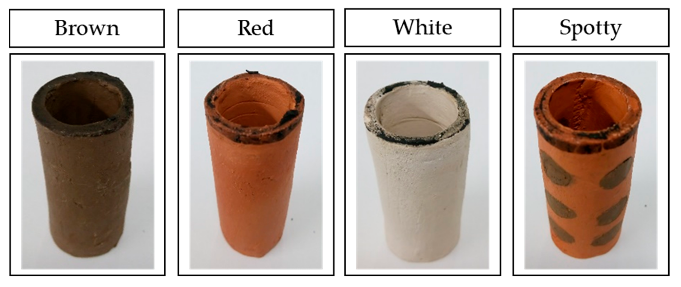
Ceramic separators were made in a cylindrical shape with one end sealed. Bottom sealed cylinders were 55 mm long, with inner diameter of 18 mm and thickens of 3 mm. The ceramic separators used for the study are shown in Figure 1. As these were all hand made, and then fired, the dimensions vary by a few millimetres between samples.
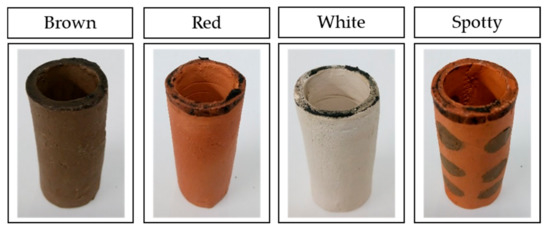
Figure 1.
Images of ceramic cylinders used in the study. Spotty ceramics are exemplars of red ceramic-based with brown spots, named RB.
As well as making separators from a single clay type (brown, red or white ceramic), combinations of the three raw materials were used to produce novel “spotty” separators. This type of ceramic separators was expected to offer additional benefits to the MFCs, resulting from the combination of the two clay types.
2.2. Microbial Fuel Cell Designs, Inoculation and Operation
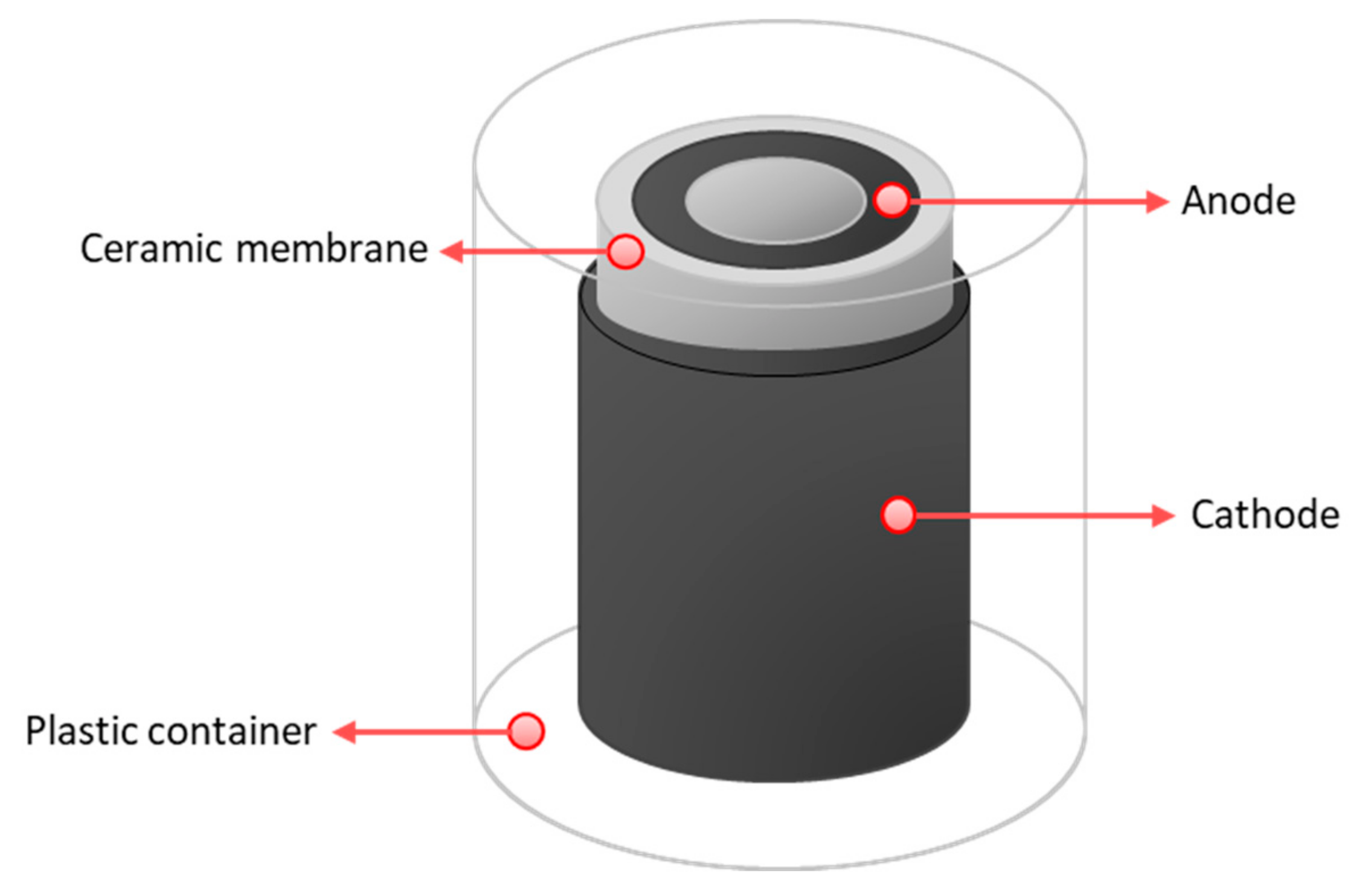
Cylindrical MFCs were built to be tested as ceramic separators. For the anode, plain carbon fibre veil (20 g·m−2 carbon loading; PRF Composite Materials Poole, Dorset, UK) was cut into 270 cm2 (30 × 9 cm) and then folded to fit into the anode chambers. A hot-pressed activated carbon cathode, prepared as previously described [27] with a total surface area of 35 cm2, was placed onto the separator; this cathode was open to air. MFCs were inserted in 50 mL plastic containers, which was partially filled with water to keep the moisture of the cathodes. This allowed wetting of the air-cathodes, and improved the cathode performance. The schematic diagram of MFC design used in this study is shown in Figure 2 and the actual tested design is shown in Figure S2.
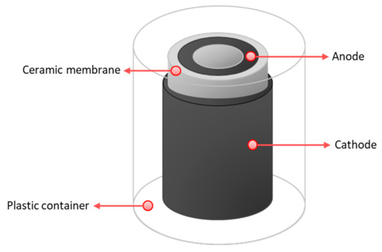
Figure 2.
Schematic diagram of an MFC reactor used in the study.
Anaerobic sewage sludge from a local wastewater treatment plant (Wessex Water, Saltford, UK) was used to inoculate the MFCs, after being enriched with 1% tryptone and 0.5% yeast extract. MFCs were fed in batch (once every 1–3 days) with neat human urine, donated from consenting adults. Typically, the urine had a pH of 9.2–9.3, and conductivity of 28–30 mS·cm−1. In each feed, 5 mL of anolyte was replaced with fresh feedstock. The total volume of anolyte was 10 mL.
Throughout the work, variable external loads were connected to each MFC, which were determined based on polarisation runs that were carried out periodically. All tests were carried out in triplicates.
2.3. Polarisation Test and Data Logging
For polarisation experiments, various external resistances ranged from 4.8 kΩ to 4 Ω were loaded every 5 min and the potential between the anode and cathode was recorded every 30 s. Power output of the MFCs was monitored in real time in volts (V) against time using a multi-channel Agilent 34972A DAQ unit (Agilent Technologies, California, USA) every 5 min. All experiments were carried out in a temperature-controlled environment, at 22 ± 2 °C.
2.4. Physiochemical Property Analysis of Ceramic Separators
2.4.1. Porosity Investigation
Porosity investigation was carried out using both the ASTM (American Society for Testing and Materials) C373 procedure [28] and mercury intrusion porosimetry (PASCAL 140, CE Instruments, Wigan, UK and CARLO ERBA Poro 2000, Science Exchange, Cobham, UK) methods. Prior to the analysis, single compound separator samples were thermally treated at 500 °C to remove even the very limited presence of organics and then subjected to thermal gravimetric analysis (TGA) to detect the presence of residues. The TGA results showed no evident weight loss, except for a very low amount at low temperature, probably corresponding to the evolution of humidity. The overall residue was below the sensitivity of the instrument (0.1%) and no thermal effects were noticed. Mercury intrusion tests were performed once for each sample to find surface area, porosity, pore size, and pore distribution data. ASTM tests were repeated on five different specimens for each sample, and the structural properties of a material such as bulk density, apparent porosity, and specific gravity to the precision of approx. ±0.1% were determined.
Scanning electron microscopy (SEM) analysis of the ceramic surface and cross-section was performed using Quanta FEG 650 (Thermo Fisher Scientific, Massachusetts, USA) and JSM-5500 (JEOL, Tokyo, Japan). The cross-section images were processed to find percentage porosity using MATLAB (MathWorks, Massachusetts, USA).
2.4.2. Composition Analysis
Energy dispersive X-ray Spectroscopy (EDXS) analysis was carried out to determine chemical compositions of the ceramics (Quanta FEG 650, Thermo Fisher Scientific, Massachusetts, USA).
2.5. Statistical Analysis
To evaluate if the differences between test ceramics in terms of power generation performance are statistically meaningful, analysis of variance (ANOVA: ordinary one-way) was performed using GraphPad Prism 8 (GraphPad Software, California, USA). Power produced in joules from 4 feeding cycles in days between 44 and 52 were calculated. This resulted in 108 data points for all 9 types of ceramic separator.
3. Results and Discussion
3.1. Effect of Ceramic Type on MFC Performance
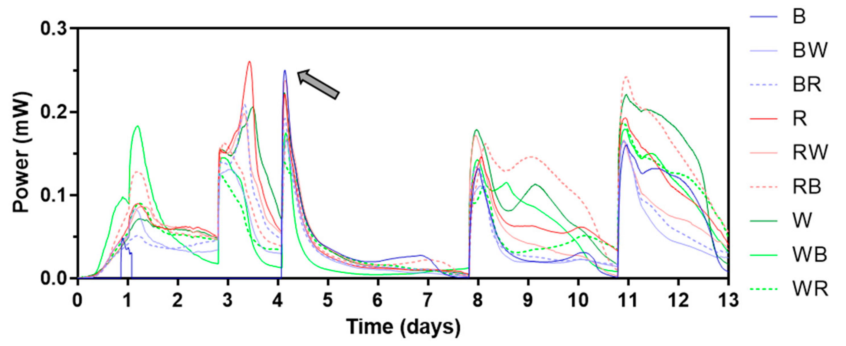
During the electroactive biofilm maturing period, beginning with inoculation, initially a 1 kΩ external resistor was connected. Then, it was replaced by a heavier load (lower resistance value) as the cell voltage levels reached 300 mV, which took between 2 and 10 days, each cell differed. Figure 3 shows power outputs of the first 13 days of MFC operation. The different types of ceramic separators tested are illustrated in Figure S1. While most of the MFCs showed similar power generating patterns, which are typical for batch-fed MFCs in initial stage, no voltage could be measured from MFCs with brown ceramic separators for the first 3 batch feedings (until day 4). This was thought to be due to its relatively low permeability. All MFCs had air breathing cathodes which use atmospheric oxygen as a terminal electron acceptor thus open to air. This type of cathode can be run in dry condition where external addition of catholyte is not required. In fact, for this type of cathode, flooding should be prevented for efficient MFC operation. However, keeping the cathode in wet conditions (but not flooded) can improve its performance by facilitating the continuous flow of cations from the anode, especially for cathodes with no electrochemically efficient catalysts such as Pt or Pt alloys. Water formation as a “circuit-closing” reaction of MFC electricity generation is well studied [29]. Also, catholyte production mainly by electro-osmotic drag is common for MFCs with ceramic separators that are non-ion-selective and relatively highly porous [22,30]. In this study, therefore MFC operation started without any initial catholyte present. However, after this finding, it was decided to add water to the cathode chambers to maintain the wet condition of both cathode and separator.
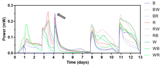
Figure 3.
Power output profile of the first 13 days. The grey arrow indicates when continuous reading of power from brown ceramic separators began. Letters “B”, “R”, and “W” stand for “brown”, “red”, and “white” respectively. Data represent average values from triplicates of each ceramic type. See Figure S1 for the different types of ceramic separators.
Once catholyte was present, peak values of power output for all MFCs increased in each batch feeding cycle then stabilised, implying the anodic biofilms matured. Figure 4 presents power output profiles of all test ceramics between day 43 and day 48, when MFCs were fully matured. Single composition ceramic types (brown, red, and white) produced similar levels of peak power in each feed, whereas difference in peak power was more distinct in spotty ceramics. The best-performing ceramic was RB (red ceramic-based with brown spots) producing 491.1 ± 1.7 µW of peak power. Although all single composition ceramic types showed similar peak power, power output of brown ceramic decreased more rapidly than the other two ceramics, red and white. This was the case for brown ceramic-based spotty types of BW (brown ceramic-based with white spots) and BR (brown ceramic-based with red spots). This could be related to the low permeability of brown ceramic, resulting in poor ion transfer through the ceramic matrix, which was also the reason both the separator and cathode electrode required hydration. When comparing the area under curve (AUC) of each ceramic tested, red and WB (white ceramic-based with brown spots) generated the highest output in two groups of single composition and spotty ceramic type. Overall, spotty types outperformed single composition separators both in terms of peak power and AUC, suggesting a great potential of this ceramic design type as an MFC separator.

Figure 4.
Power outputs of MFCs with test ceramics between day 43 and day 48; single composition ceramics (a), spotty ceramics (b), and area under curve of each batch feed (c). Data represent average values from triplicates of each ceramic type.
The difference in performance of test ceramics was also observed from the power curves. Figure 5 shows power curves of all ceramics from polarisation tests that were carried out in week 9. For single material ceramic types, the best-performing ceramic was red with a PMAX of 670.5 ± 64.8 µW. This was 14.9% and 22.5% higher than white (570.5 ± 48.0 µW) and brown (519.9 ± 53.6 µW) respectively. On the other hand, all spotty ceramics showed similar levels of PMAX, although white-based ceramics produced the highest power outputs (717.7 ± 29.9 µW for WB and 715.3 ± 73.0 µW for WR) and currents. Again, better performance of spotty ceramics in comparison to single composition ceramics (except red and red-based ceramics) was confirmed (Figure 5c). The statistical results support the findings. The ordinary one-way ANOVA test results indicate that there were significant differences (p-value less than 0.05) between nine test ceramics for power production of each feeding cycle (p-value: < 0.001).

Figure 5.
Power curves and PMAX of MFCs with test ceramics; single composition ceramics (a), spotty ceramics (b), and PMAX from each power curve (c). Data represent average values from triplicates of each ceramic type, and error bars of power curves are not shown for clarity.
3.2. Long-Term Operation
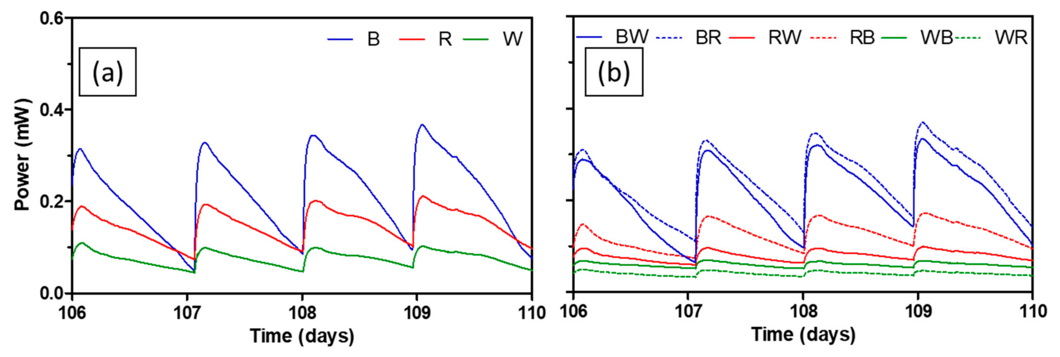
For the practical implementation of MFC technology, long-term performance should be verified. Figure 6 depicts power generating performance of all test ceramics between day 106 and day 110. Average peak power of brown ceramic during this period was 338.1 ± 22.8 µW, which was 26.4% lower compared to the peak power of the same ceramic during the mid-term. Brown-based spotty ceramics (BW and BR) showed similar extent of performance decrease of 30.7% and 28.1% respectively. This is interesting since the brown ceramic was the least performing separator during the mid-term, in terms of both peak power and AUC. On the other hand, peak power of red and white that performed better in the mid-term decreased by 55.4% and 76.9% respectively. Peak power of spotty ceramics based on both red and white also reduced by around 66.8–88.2%. The trend of change in peak power of each ceramic over the whole experimental period can be seen in Figure S3.
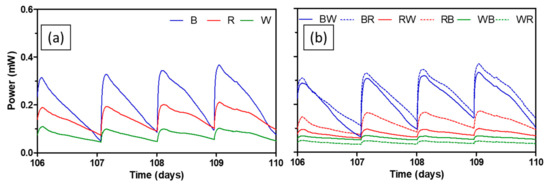
Figure 6.
Power output levels of MFCs with test ceramics between day 106 and day 110; single composition ceramics (a), spotty ceramics (b). Data represent average values from triplicates of each ceramic type.
Performance decrease in MFC power generation is common due to an increase of internal resistance as a result of increasing thickness of the anodic biofilm, bio- and abiotic fouling of porous materials including electrodes and separators, or microbially influenced corrosion [31,32,33]. Although fully hydrolysed urine was used in this study as a feedstock, a small degree of precipitation of uric salts was expected since neat urine was used without pre-treatment such as filtration. This could aggravate the performance of ceramic separators by blocking pores (abiotic fouling). Interestingly, during MFC operation, a significant amount of precipitation on the cathode was observed in the most of MFCs, which could hinder the proton transfer and subsequently slow down the oxygen reduction reaction. This is mainly driven by electro-osmotic drag and the number of ions diffused is strongly related to MFC performance [22,34]. Therefore, it is thought that the initially better performing ceramics such as red and white which also had smaller pore sizes (Table 1 and Figure 7) had more propensity towards membrane fouling in the long run. To tackle this type of membrane fouling, using alkaline catholyte, or periodic washing of both the cathode and separator can be implemented.

Table 1.
Results of porosity and pore size measurements.

Figure 7.
Pore size distribution for brown (a), red (b) and white (c) ceramic samples.
3.3. Physiochemical Properties of Test Ceramics
Mercury intrusion porosimetry and water absorption (ASTM C373) methods were applied since they are appropriate for a mesoporous (pore diameters between 2 nm and 50 nm) and macroporous (pore diameters of greater than 50 nm) materials such as this. The porosity and pore size distribution of single composition ceramics are shown in Table 1 and Figure 7. Although there are some differences between the two measurement methods, the porosity in all materials ranges between 22% and 27%, which is relatively high in comparison to other MFC ceramic separators previously tested [20,21,23]. Increased porosity by lowering firing temperature was confirmed by water absorption measurements (data not shown). Overall, brown ceramic is the least porous as speculated and this explains why addition of catholyte for brown ceramic was needed initially (Figure 3). Porosities of the other two ceramics are similar although porosity of white ceramic is slightly higher. As shown in Figure 7, the distribution of pore radii for all ceramics follows a log-Weibull distribution, peaking at less than 100 nm. The average pore size (diameter) is highest for the brown at 188 nm which is almost twice the size of the other two, making them all macroporous. This is of interest as pores over 1 µm may allow the passage of bacteria across the chambers. However, not all the pores will be open-ended and the likelihood of a bacterium finding an open-ended pore in the entire 3 mm thickness is low. The percentage of pores which are larger than 1 µm in radius is 1.92%, 1.32% and 0.56% for brown, red, and white ceramic respectively (Table S2), which is sufficiently low to assume that bacterial cross-contamination between MFC compartments is unlikely.
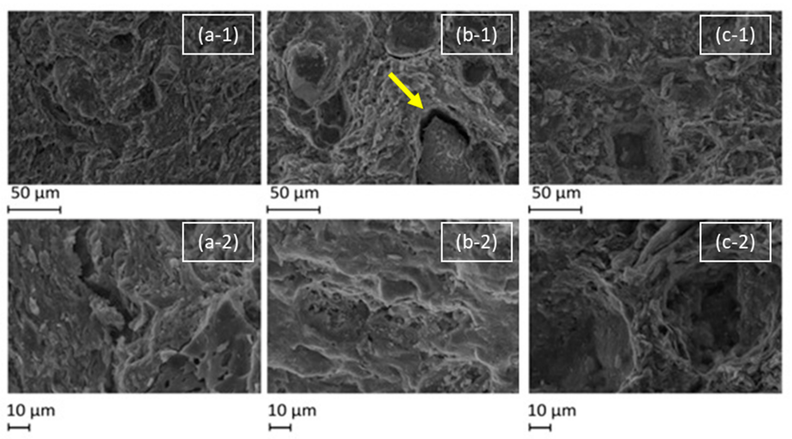
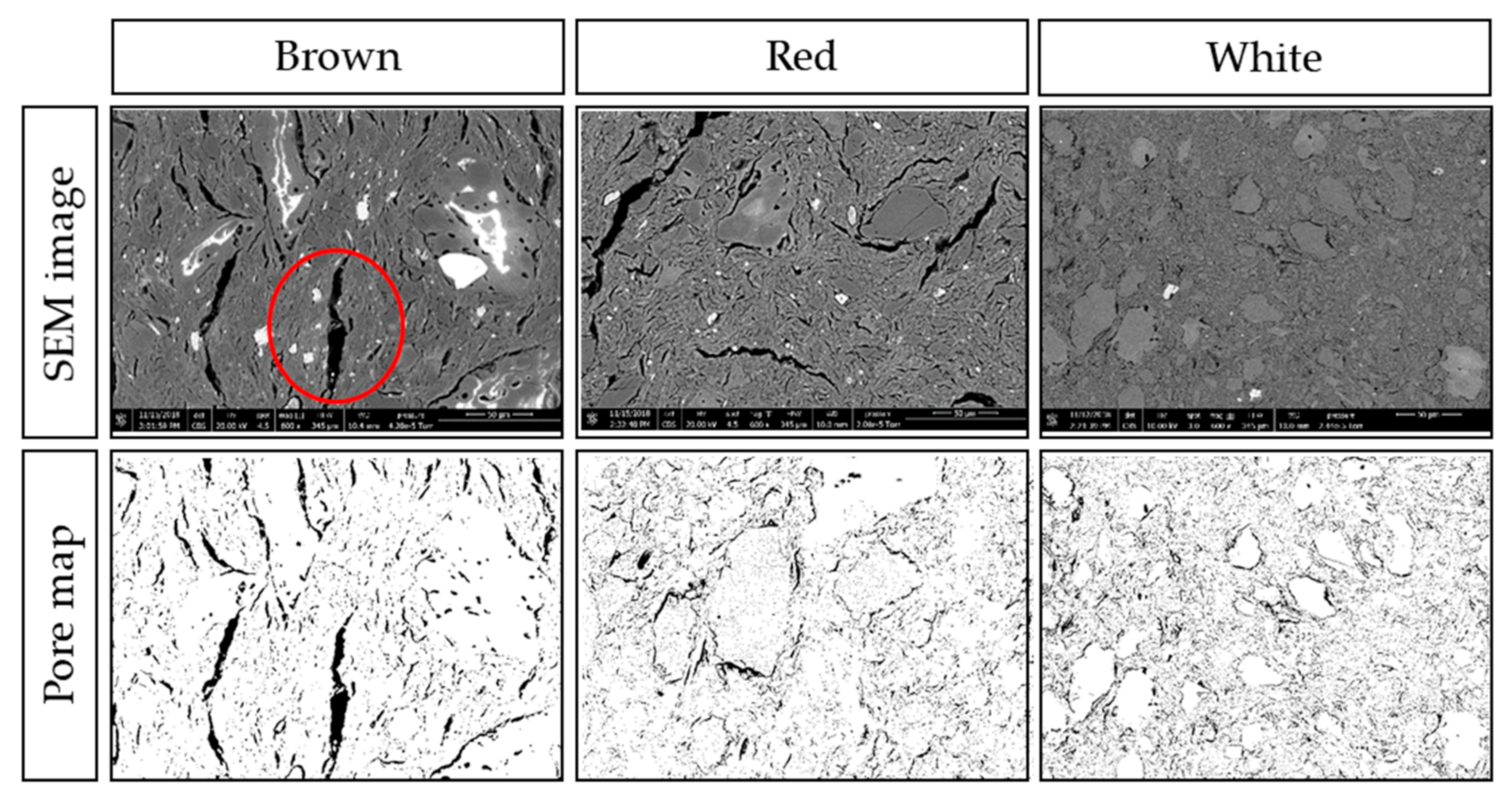
The SEM images (Figure 8 and Figure 9) show that the surfaces of all ceramics are heterogeneous, with a range of features including smooth regions, cracks, vacancies, pores, and flakes. It is possible to see the inclusions of chamotte and other materials within the ceramic matrix, particularly in the cross-section images (Figure 9). From the surface images at lower magnification, in Figure 8, it is possible to see some inclusions on the surface, and in the case of the red ceramic, a micro-size crack is visible around one of these inclusions. At the higher magnification, some pores of roughly 1 µm are visible.
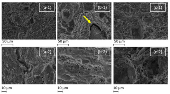
Figure 8.
SEM micrographs of the surface of test ceramics: brown (a), red (b) and white (c) under magnifications of 500 (-1) and 1000 (-2) times. The yellow arrow points to a visible crack.
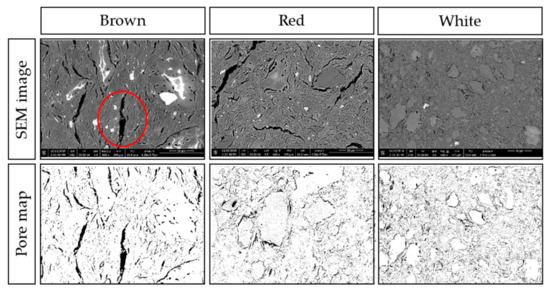
Figure 9.
Cross-section SEM micrographs at 600x magnification of brown, white, and red ceramics with the associated pore maps.
Figure 9 shows the micro-scale cracks within the matrix, and the inclusions of different compositions and dimensions. Both brown and red ceramics have cracks of more than 10 µm in width and 100 µm in length. The largest crack in brown ceramic, circled in the bottom central part of the image, is 15 µm wide and 125 µm long. Some inclusions show as white in the SEM, and others have white regions, which is an artefact of the surface of the specimen. White ceramic, while also exhibiting cracks around inclusions, has instead much smaller pores. As the micro-scale cracks are a result of the matrix differential shrinkage during cooling, and the white ceramic has much smaller cracks, this suggests that the white ceramic suffered less differential shrinkage and thus less thermal stress during firing. The calculated percentage porosity from these images are 8.5%, 12.2% and 10.7% for brown, red, and white, respectively.
In summary, the brown ceramic has denser matrix with bigger pores in comparison to the red and white ceramics. This could be its intrinsic nature due to its composition or the adjusted firing temperature, perhaps both. Again, this can explain its initial underperformance but less propensity towards membrane fouling.
3.4. Composition and Structure of Ceramic Separators
The chemical composition of ceramics is shown in Table 2, with values from both the manufacturer data sheet and from EDXS analysis. The primary elements of all the ceramics were silicon and aluminium. The brown ceramic interestingly contains 4.8% MnO, which may be acting as a catalyst for the oxygen reduction reaction (ORR). Manganese oxides have attracted attention as a cost-effective alternative to platinum catalysts at the cathode in electrochemical energy conversion systems. While many stoichiometries have been investigated and each has different effects, in general manganese has been demonstrated to improve ORR kinetics by promoting the more efficient four-electron ORR pathway over the two-electron pathway [35]. Several papers use MnOx with carbon nanotubes as a catalyst in MFCs and find that in comparison to Pt/C catalyst it performs better [36], or similar [37,38,39]. However, in all of these papers, the manganese oxides were always MnO2 or MnO3, and were applied at the cathode surface, so without further investigation of our system, it is not clear whether the manganese is indeed acting as a catalyst or if other properties of the brown ceramic are dominant.

Table 2.
Chemical composition of ceramics used.
4. Conclusions
Commercially available ceramic materials with different compositions have been tested as MFC separators and as a (potential) chassis or vessel. Intensive physiochemical property analysis revealed that brown ceramic has lower porosity and larger pores in comparison to red and white ceramics. Single composition brown ceramic required cathode hydration due to its low porosity, which resulted in relatively poor performance initially. However, the brown ceramic separator is a more suitable choice for long-term operation, by outperforming other single composition ceramic types. This study confirms that pore size as well as porosity plays an important role in ceramic performance in MFCs.
Another important finding is the potential of spotty type ceramics. Although some of the spotty type ceramics had a leakage issue due to the nature of handmade ceramics and difference in extent of shrinkage of two materials during firing, in most cases spotty ceramics outperformed single composition types. Therefore, composite design could also be a way of enhancing the function of ceramic separators, as well as fine-tuning porosity and pore size. This may be particularly important in cases where the cathode is inside the cylinder (and the anode outside), which is an MFC topology that allows for catholyte synthesis [22]; in this way, it is possible to combine high power performance and high catholyte quality.
Ceramic separators for MFCs are still very much a lab making and not subject to rigorous manufacturing and quality control procedures; this is by far the main consideration that anyone working in this field should take seriously into account. Fab labs or facilities, whose core competency is the fabrication of new structures from new materials, could be the first option for scientists, since ceramics manufacturers, whose (successful) business model is distant from research, will be unable to engage, unless such proposition made sense. In the case when scientific labs can employ a rigorous fabrication process, then physical parameters (thickness, density/porosity and pore size) should take priority before physicochemical parameters can become the focus.
Lastly, the use of low-cost, locally sourced ceramic separators of customisable shape for high performance MFCs would allow for the design and implementation of this technology into the built environment, integrated into a living architecture [25].
Supplementary Materials
The following are available online at https://www.mdpi.com/1996-1073/12/21/4071/s1, Figure S1: All ceramic cylinder membranes tested in the study, Figure S2: Photos of experimental set-up (left) and individual MFCs (right), Figure S3: Temporal change of peak power of test ceramics, Table S1: Chemical compositions and physical properties of tested ceramic materials, Table S2: Percentage relative volume of pores for test ceramics.
Author Contributions
J.Y. and L.W. performed the MFC experiments. J.Y., L.W., N.R. and G.P. analysed materials and data. J.Y., L.W. and N.R. wrote the draft manuscript. V.M.S. supervised the EDXS and porosity measurements. I.I., J.G., M.M.H. and V.M.S reviewed and edited the manuscript. I.I. and J.G. also acquired the funding and provided an idea of the “spotty ceramic membranes”. All authors have approved the submitted manuscript.
Funding
This research was funded by the European Commission Horizon 2020 FET-OPEN Living Architecture Project (grant no. 686585).
Acknowledgments
The authors would like to thank Barbara Imhof and Waltraut Hoheneder (LIQUIFER Systems Group GmbH) for providing ceramic materials used for experiments.
Conflicts of Interest
The authors declare no conflict of interest.
References
- Dong, Y.; Qu, Y.; He, W.; Du, Y.; Liu, J.; Han, X.; Feng, Y. A 90-liter stackable baffled microbial fuel cell for brewery wastewater treatment based on energy self-sufficient mode. Bioresour. Technol. 2015, 195, 66–72. [Google Scholar] [CrossRef] [PubMed]
- Goto, Y.; Yoshida, N. Scaling up Microbial Fuel Cells for Treating Swine Wastewater. Water 2019, 11, 1803. [Google Scholar] [CrossRef]
- Ge, Z.; He, Z. Long-term performance of a 200 liter modularized microbial fuel cell system treating municipal wastewater: Treatment, energy, and cost. Environ. Sci. Water Res. Technol. 2016, 2, 274–281. [Google Scholar] [CrossRef]
- Liang, P.; Duan, R.; Jiang, Y.; Zhang, X.; Qiu, Y.; Huang, X. One-year operation of 1000-L modularized microbial fuel cell for municipal wastewater treatment. Water Res. 2018, 141, 1–8. [Google Scholar] [CrossRef] [PubMed]
- Online TOX/BOD System—KORBI. Available online: http://www.korbi.com/eng/products_type/habt-3000/?pageds=1&k=BOD (accessed on 6 September 2019).
- Trapero, J.R.; Horcajada, L.; Linares, J.J.; Lobato, J. Is microbial fuel cell technology ready? An economic answer towards industrial commercialization. Appl. Energy 2017, 185, 698–707. [Google Scholar] [CrossRef]
- Santoro, C.; Arbizzani, C.; Erable, B.; Ieropoulos, I. Microbial fuel cells: From fundamentals to applications. A review. J. Power Sources 2017, 356, 225–244. [Google Scholar] [CrossRef]
- Kondaveeti, S.; Kakarla, R.; Kim, H.S.; Kim, B.G.; Min, B. The performance and long-term stability of low-cost separators in single-chamber bottle-type microbial fuel cells. Environ. Technol. 2018, 39, 288–297. [Google Scholar] [CrossRef]
- Liu, H.; Logan, B.E. Electricity generation using an air-cathode single chamber microbial fuel cell in the presence and absence of a proton exchange membrane. Environ. Sci. Technol. 2004, 38, 4040–4046. [Google Scholar] [CrossRef]
- Palanisamy, G.; Jung, H.Y.; Sadhasivam, T.; Kurkuri, M.D.; Kim, S.C.; Roh, S.H. A comprehensive review on microbial fuel cell technologies: Processes, utilization, and advanced developments in electrodes and membranes. J. Clean. Prod. 2019, 221, 598–621. [Google Scholar] [CrossRef]
- Koók, L.; Bakonyi, P.; Harnisch, F.; Kretzschmar, J.; Chae, K.J.; Zhen, G.; Kumar, G.; Rózsenberszki, T.; Tóth, G.; Nemestóthy, N.; et al. Biofouling of membranes in microbial electrochemical technologies: Causes, characterization methods and mitigation strategies. Bioresour. Technol. 2019, 279, 327–338. [Google Scholar] [CrossRef]
- Bajracharya, S.; Sharma, M.; Mohanakrishna, G.; Dominguez Benneton, X.; Strik, D.P.; Sarma, P.M.; Pant, D. An overview on emerging bioelectrochemical systems (BESs): Technology for sustainable electricity, waste remediation, resource recovery, chemical production and beyond. Renew. Energy 2016, 98, 153–170. [Google Scholar] [CrossRef]
- Oliot, M.; Galier, S.; Roux de Balmann, H.; Bergel, A. Ion transport in microbial fuel cells: Key roles, theory and critical review. Appl. Energy 2016, 183, 1682–1704. [Google Scholar] [CrossRef]
- Dhar, B.R.; Lee, H.S. Membranes for bioelectrochemical systems: Challenges and research advances. Environ. Technol. 2013, 34, 1751–1764. [Google Scholar] [CrossRef] [PubMed]
- Jana, P.S.; Behera, M.; Ghangrekar, M.M. Performance comparison of up-flow microbial fuel cells fabricated using proton exchange membrane and earthen cylinder. Int. J. Hydrog. Energy 2010, 35, 5681–5686. [Google Scholar] [CrossRef]
- Gajda, I.; Greenman, J.; Santoro, C.; Serov, A.; Atanassov, P.; Melhuish, C.; Ieropoulos, I.A. Multi-functional microbial fuel cells for power, treatment and electro-osmotic purification of urine. J. Chem. Technol. Biotechnol. 2019, 94, 2098–2106. [Google Scholar] [CrossRef]
- Winfield, J.; Gajda, I.; Greenman, J.; Ieropoulos, I. A review into the use of ceramics in microbial fuel cells. Bioresour. Technol. 2016, 215, 296–303. [Google Scholar] [CrossRef]
- Santoro, C.; Flores-Cadengo, C.; Soavi, F.; Kodali, M.; Merino-Jimenez, I.; Gajda, I.; Greenman, J.; Ieropoulos, I.; Atanassov, P. Ceramic microbial fuel cells stack: Power generation in standard and supercapacitive mode. Sci. Rep. 2018, 8, 3281. [Google Scholar] [CrossRef]
- Baker, R.W. Membrane Separation. In Encyclopedia of Separation Science; Elsevier: Cambridge, MA, USA, 2000; pp. 189–210. [Google Scholar]
- Winfield, J.; Greenman, J.; Huson, D.; Ieropoulos, I. Comparing terracotta and earthenware for multiple functionalities in microbial fuel cells. Bioprocess Biosyst. Eng. 2013, 36, 1913–1921. [Google Scholar] [CrossRef]
- Pasternak, G.; Greenman, J.; Ieropoulos, I. Comprehensive study on ceramic membranes for low-cost microbial fuel cells. ChemSusChem 2016, 9, 88–96. [Google Scholar] [CrossRef]
- Merino Jimenez, I.; Greenman, J.; Ieropoulos, I. Electricity and catholyte production from ceramic MFCs treating urine. Int. J. Hydrog. Energy 2017, 42, 1791–1799. [Google Scholar] [CrossRef]
- Khalili, H.B.; Mohebbi-Kalhori, D.; Afarani, M.S. Microbial fuel cell (MFC) using commercially available unglazed ceramic wares: Low-cost ceramic separators suitable for scale-up. Int. J. Hydrog. Energy 2017, 42, 8233–8241. [Google Scholar] [CrossRef]
- Winfield, J.; Chambers, L.D.; Rossiter, J.; Greenman, J.; Ieropoulos, I. Urine-activated origami microbial fuel cells to signal proof of life. J. Mater. Chem. A 2015, 3, 7058–7065. [Google Scholar] [CrossRef]
- Living Architecture—Transform Our Habitats from Inert Spaces into Programmable Sites. Available online: https://livingarchitecture-h2020.eu/ (accessed on 10 September 2019).
- Djangang, C.N.; Elimbi, A.; Melo, U.C.; Lecomte, G.L.; Nkoumbou, C.; Soro, J.; Bonnet, J.P.; Blanchart, P.; Njopwouo, D. Sintering of clay-chamotte ceramic composites for refractory bricks. Ceram. Int. 2008, 34, 1207–1213. [Google Scholar] [CrossRef]
- You, J.; Walter, X.A.; Greenman, J.; Melhuish, C.; Ieropoulos, I. Stability and reliability of anodic biofilms under different feedstock conditions: Towards microbial fuel cell sensors. Sens. Bio-Sens. Res. 2015, 6, 43–50. [Google Scholar] [CrossRef]
- ASTM C373-18, Standard Test Methods for Determination of Water Absorption and Associated Properties by Vacuum Method for Pressed Ceramic Tiles and Glass Tiles and Boil Method for Extruded Ceramic Tiles and Non-Tile Fired Ceramic Whiteware Products; ASTM International: West Conshohocken, PA, USA, 2018.
- Logan, B.E.; Hamelers, B.; Rozendal, R.; Schröder, U.; Keller, J.; Freguia, S.; Aelterman, P.; Verstraete, W.; Rabaey, K. Microbial fuel cells: Methodology and technology. Environ. Sci. Technol. 2006, 40, 5181–5192. [Google Scholar] [CrossRef] [PubMed]
- Gajda, I.; Greenman, J.; Melhuish, C.; Ieropoulos, I. Simultaneous electricity generation and microbially-assisted electrosynthesis in ceramic MFCs. Bioelectrochemistry 2015, 104, 58–64. [Google Scholar] [CrossRef] [PubMed]
- Malvankar, N.S.; Tuominen, M.T.; Lovley, D.R. Biofilm conductivity is a decisive variable for high-current-density Geobacter sulfurreducens microbial fuel cells. Energy Environ. Sci. 2012, 5, 5790. [Google Scholar] [CrossRef]
- Kundu, P.P.; Dutta, K.; Kumar, P.; Bharti, R.P.; Kumar, V.; Kundu, P.P. Polymer Electrolyte Membranes for Microbial Fuel Cells: Part A. Nafion-Based Membranes. In Progress and Recent Trends in Microbial Fuel Cells; Elsevier: Amsterdam, The Netherlands, 2018; pp. 47–72. ISBN 978-0-444-64017-8. [Google Scholar]
- Natarajan, K.A. Biofouling and microbially influenced corrosion. In Biotechnology of Metals, 1st ed.; Elsevier: Amsterdam, The Netherlands, 2018; pp. 355–393. ISBN 978-0-12-804022-5. [Google Scholar]
- Gajda, I.; Greenman, J.; Melhuish, C.; Santoro, C.; Li, B.; Cristiani, P.; Ieropoulos, I. Electro-osmotic-based catholyte production by Microbial Fuel Cells for carbon capture. Water Res. 2015, 86, 108–115. [Google Scholar] [CrossRef]
- Stoerzinger, K.A.; Risch, M.; Han, B.; Shao-Horn, Y. Recent Insights into Manganese Oxides in Catalyzing Oxygen Reduction Kinetics. ACS Catal. 2015, 5, 6021–6031. [Google Scholar] [CrossRef]
- Zhang, Y.; Hu, Y.; Li, S.; Sun, J.; Hou, B. Manganese dioxide-coated carbon nanotubes as an improved cathodic catalyst for oxygen reduction in a microbial fuel cell. J. Power Sources 2011, 196, 9284–9289. [Google Scholar] [CrossRef]
- Rout, S.; Nayak, A.K.; Varanasi, J.L.; Pradhan, D.; Das, D. Enhanced energy recovery by manganese oxide/reduced graphene oxide nanocomposite as an air-cathode electrode in the single-chambered microbial fuel cell. J. Electroanal. Chem. 2018, 815, 1–7. [Google Scholar] [CrossRef]
- Shahbazi Farahani, F.; Mecheri, B.; Reza Majidi, M.; Costa de Oliveira, M.A.; D’Epifanio, A.; Zurlo, F.; Placidi, E.; Arciprete, F.; Licoccia, S. MnOx-based electrocatalysts for enhanced oxygen reduction in microbial fuel cell air cathodes. J. Power Sources 2018, 390, 45–53. [Google Scholar] [CrossRef]
- Zhang, L.; Liu, C.; Zhuang, L.; Li, W.; Zhou, S.; Zhang, J. Manganese dioxide as an alternative cathodic catalyst to platinum in microbial fuel cells. Biosens. Bioelectron. 2009, 24, 2825–2829. [Google Scholar] [CrossRef] [PubMed]
© 2019 by the authors. Licensee MDPI, Basel, Switzerland. This article is an open access article distributed under the terms and conditions of the Creative Commons Attribution (CC BY) license (http://creativecommons.org/licenses/by/4.0/).

