Article

Analysis and Comparison of Some Low-Temperature Heat Sources for Heat Pumps

by
Pavel Neuberger
* and
Radomír Adamovský
Department of Mechanical Engineering, Faculty of Engineering, Czech University of Life Sciences Prague, Kamýcká 129, 165 21 Prague-Suchdol, Czech Republic
*
Author to whom correspondence should be addressed.
Energies 2019, 12(10), 1853; https://doi.org/10.3390/en12101853
Submission received: 12 April 2019 / Revised: 9 May 2019 / Accepted: 13 May 2019 / Published: 15 May 2019
(This article belongs to the Special Issue Sustainable Energy Reviews)

Abstract

:
The efficiency of a heat pump energy system is significantly influenced by its low-temperature heat source. This paper presents the results of operational monitoring, analysis and comparison of heat transfer fluid temperatures, outputs and extracted energies at the most widely used low temperature heat sources within 218 days of a heating period. The monitoring involved horizontal ground heat exchangers (HGHEs) of linear and Slinky type, vertical ground heat exchangers (VGHEs) with single and double U-tube exchanger as well as the ambient air. The results of the verification indicated that it was not possible to specify clearly the most advantageous low-temperature heat source that meets the requirements of the efficiency of the heat pump operation. The highest average heat transfer fluid temperatures were achieved at linear HGHE (8.13 ± 4.50 °C) and double U-tube VGHE (8.13 ± 3.12 °C). The highest average specific heat output 59.97 ± 41.80 W/m2 and specific energy extracted from the ground mass 2723.40 ± 1785.58 kJ/m2·day were recorded at single U-tube VGHE. The lowest thermal resistance value of 0.07 K·m2/W, specifying the efficiency of the heat transfer process between the ground mass and the heat transfer fluid, was monitored at linear HGHE. The use of ambient air as a low-temperature heat pump source was considered to be the least advantageous in terms of its temperature parameters.

1. Introduction

Conventional heating, ventilation and air conditioning (HVAC) systems use fossil fuels and thus contribute significantly to deterioration of environmental quality [1]. According to Peréze et al. [1], HVAC systems account for almost 50% of the total energy consumption in modern buildings. These facts evoke an urgent need for research in energy-efficient systems using renewable energy sources. Energy systems using renewable and sustainable sources of energy, and also allowing the use of the part of energy called anergy (unusable in the sense of the 2nd Law of Thermodynamics), can be considered in the above sense as efficient systems with a high potential to meet the requirements of reducing fossil fuel consumption and environmental protection. These requirements are very well fulfilled by energy systems with heat pumps.
Ambient air, water, rock and ground masses are the most widely used low-temperature energy sources for heat pumps.
These low-temperature energy sources are considered to be more or less renewable and sustainable in the sense of their specification according to Stefánsson [2,3], who explained the term "renewable" as a property of an energy source and "sustainable" as a way of using the source. Ambient air can be considered a renewable and sustainable energy source within the meaning of this definition. Ground and rock masses are generally considered to be renewable sources of energy [4,5]; however, they are quite different from solar or wind energy, due to the longer periods of energy extraction and transfer [6,7]. Rybach defined a sustainable system as a system that is able to maintain heat extraction options for a long time [8]. In this context, both ground and rock masses can lose their sustainability due to long-term and unbalanced heat loads [9,10].
Heat pumps using air as a low-temperature source are frequently installed, given the lower investment costs and easier installation. Systems using groundwater or surface water are beneficial in terms of realization and energy efficiency. However, the use of these systems is rightfully restricted by the requirements of natural water resources protection. The rock mass seems to be advantageous as a low-temperature source of energy in buildings with insufficient surrounding area and with requirements for heating the building in winter period and its cooling in summer period. The installation of these low-temperature energy sources is the most demanding in terms of investment. The ground mass stands for a compromise among the low-temperature heat sources. This low-temperature source is not completely dependent on ambient air temperature and its implementation is less demanding than in the case of a rock mass. There is also no direct negative impact on natural water resources. Nevertheless, these systems require a sufficient surface area for the installation of a heat exchanger.
The temperatures of the heat transfer fluids, the heat outputs of the low-temperature sources and the energy extracted from the low-temperature sources are important parameters influencing the efficiency and performance of the heat pumps [11].
The importance of temperature of the heat transfer fluid supplied to the heat pump evaporator results from the reversed Carnot cycle. Considering the constant temperature of condensation of the working substance in the heat pump condenser, a higher temperature of the evaporation in the heat pump evaporator has a positive influence on the effect (heating factor) of the whole circulation [12]. The temperature of evaporation of the working substance is closely related to the temperature of the heat transfer fluid supplied to the evaporator of the heat pump. The heat output of the low-temperature source can influence the extracted heat output and power input of the heat pump drive. The energy extracted from the low-temperature source affects its energy potential and, as a result, the efficiency and lifetime of the entire system [7,13].
Michopoulos and Kiriakis [14] addressed modelling of the heat transfer fluid temperatures at vertical ground heat exchangers (VGHEs). They created a model that proved good accuracy throughout the whole verification process when confirming it by experimentally observed data. Gyu et al. [15] monitored the influence of rainfall infiltration on the thermal characteristics of the ground mass and the temperature of the heat transfer fluids at horizontal ground heat exchangers (HGHEs) in the heating and cooling mode. Mesaha et al. [5] studied the changes of heat transfer fluid temperatures in VGHEs and pipe lengths during extraction and accumulation of heat in rock mass. Kayaci and Demir [16] developed a numerical model of prediction of input and output heat transfer fluid temperatures in HGHEs. The maximum deviations between the numerical and experimentally observed temperatures of the heat transfer fluids were 0.86 and 1.09 K. Ren et al. [17] monitored output, extracted heat and heat transfer fluid temperatures in VGHEs with polyethylene and steel pipes. Both the inlet and outlet temperatures of the heat transfer fluids flowing through the steel exchanger pipes during heating in winter and cooling in summer period were higher by 4.01–7.01 K than in the polyethylene exchanger pipes. Also, the specific output and the extracted energy were higher for the steel pipe exchanger. Based on the results of experiments, Remiorz et al. [18] observed that the thermal mass regeneration associated with geothermal heat flow and groundwater infiltration occurred when the heat extraction from the rock mass with VGHEs was stopped. Due to the thermal regeneration of the mass, the temperature of the heat transfer fluid increased. After a long-term heat extraction from the mass, the temperatures of the heat transfer fluids were significantly lower at the beginning of the next cycle than after a short-term extraction.
Fujii et al. [19] paid attention to the heat outputs of Slinky HGHE. Their simulation exchanger model was confirmed by the results of long-term experiments. They presented specific exchanger output of 25 W per 1 m of pipe length at a flow rate of 14 l/min. Verda et al. [6] dealt with the degradation of HGHEs heat output and output changes with respect to the depth of HGHE’s deposition in the ground mass. He indicated that the HGHE’s output is 60% higher when installing it at a depth of 2 m compared to a depth of 1 m. Dehghan et al. [20] addressed the performance of spiral VGHEs in dependence to the spacing of the coils, diameters and length of the spiral. They proved that a hundred per cent change in pipe length or spiral diameter affects the exchanger’s performance by about 10%. Lee at al. [21] were verifying the influence of specific cooling outputs of 250 W/m, 300 W/m, 350 W/m on the outlet temperature of the heat transfer fluid and effective thermal conductivity at a constant heat transfer fluid temperature at VGHEs inlet and constant overall cooling output. Zeng et al. [22] and Bae et al. [23] created a quasi-dimensional model and numerical analysis of single and double U-tube VGHEs with the aim to compare heat transfer fluid temperatures and outputs. The results of the verification showed that single U-tube exchangers had significantly higher thermal resistance than double U-tube exchangers. Double U-tube exchangers provided a better thermal performance in parallel arrangement than in serial configuration. Choi et al. [7] simulated the long-term operation of VGHE in heating and cooling mode. They monitored the thermal equilibrium of the rock mass during heat exchange, its accumulation and extraction. The average annual heat transfer fluid temperature was increasing when the output of the heat exchanger doubled during summer period compared to the output during heating period. Rise in the heat transfer fluid temperature increased the heat output but reduced the cooling output.
Larwa [9] indicated that the heat absorbed by the surface of a ground mass without HGHEs in the warm period of the year is equal to the heat transferred from the mass during the colder period. As a result of this, the average temperature of the ground mass does not change much during the given period. However, if HGHE is installed, the average temperature of the subsurface layer of the ground mass may change because the extracted heat is not generally compensated for by the amount of heat delivered during the summer. Nevertheless, the results of our HGHE verifications [24,25] proved that regeneration of the energy potential of the ground mass occurred during the stagnation of the HGHE’s operation if the heat exchanger configurations were well designed, taking into account the thermal characteristics of the ground mass. Bottareli et al. [26] analyzed the heat output and temperature of HGHE heat transfer fluids in connection with the underground heat energy storage. Two types of phase changing materials (PCM) materials using phase changes, latent heat between solid and liquid phases, were applied for accumulation. They indicated that the use of PCM was effective, as compared to gravel backfill; higher temperatures of the heat transfer fluid and higher outputs of HGHE were achieved. In the event of a thermal equilibrium of the rock mass with VGHE due to higher extraction, Dai et al. [27] recommended adding solar system to this low-temperature source. He indicated that the solar system can be efficiently used for the accelerated thermal regeneration of the rock mass. Li et al. [28] created an integrated predictive model for long-term evaluation of dynamic performance characteristics, VGHEs output and extracted heat from the rock mass. The causes of VGHE output degradation as indicated by the thermal imbalance of the mass were also analyzed. You et al. [29] elaborated very detailed overview of the main problems caused by the thermal imbalance of the mass with VGHE. They saw major problems in the fall of the mass temperature, degradation of the heat exchanger output, decrease in reliability and a possible failure. Guo and Hendel [30] paid attention to the very interesting low-temperature heat sources. In their study, they carried out detailed analysis and evaluation of the applications of heat pumps and cooling units using the energy contained in wastewater in sewerage systems, water mains, and road irrigation water.
A survey of scientific publications revealed the relevance of solving the issue of low-temperature heat sources for heat pumps. The publications dealt mainly with prediction and temperature verification of heat transfer fluids at various configurations of HGHEs and VGHEs, their specific outputs and energies extracted from the sources. Attention was also paid to the regeneration of energy extracted from the sources. The survey of scientific publications helped us to clarify the objectives of the issue and to focus the research on verifying existing knowledge and obtaining new information on the real operation of HGHEs and VGHEs.
With respect to the aforementioned, the aim of our work was to monitor, analyze and compare temperatures of heat transfer fluids, heat exchanger outputs and extracted energies at the most widely used HGHEs of linear and Slinky type, as well as at VGHEs with single and double U-tube exchangers. Also the ambient air was included in the function of low-temperature heat source for heat pumps. Acquired knowledge was analyzed in terms of its actual application.

2. Materials and Methods

The HGHEs and VGHEs were analyzed as the most frequently used types in the climatic conditions of Europe as well as in the Czech Republic.
The linear HGHE consisted of polyethylene piping PE 100RC 40 × 3.7 mm (LUNA PLAST a. s., Hořín, Czech Republic) with a length of 330 m installed in 3 loops at a span of 1 m at a depth of 1.8 m. The length of the individual loop was 54.6 m. The Slinky HGHE was made of polyethylene piping PE 100RC 32 × 2.9 mm, 200 m long, installed in 53 loops coiled into a circle 1.2 m in diameter with a loop span of 0.38 m at a depth of 1.5 m. The thermal characteristics of the soil—the coefficient of thermal conductivity λ (W/m·K), the volumetric specific heat capacity C (J/m3·K) and the coefficient of thermal conductivity a (m2/s) were determined using Isomet 2104 (manufactured by Applied Precision, Bratislava, Slovakia) at temperature t (°C) and volumetric humidity v (%). They were measured at a depth of 1.2–1.6 m, at temperature t = 12.65–13.83 °C and volumetric humidity v = 31.60–39.00 % and their values were λ = 1.39–1.57 W/m·K, C = 2.08–2.16 J/m3·K and a = 0.672–0.727 m2/s. The thermal characteristics were within a range corresponding to the most widespread type of soil in the Czech Republic. Detailed diagrams of both HGHEs were presented in publications [24] a [25].
The VGHE marked as type A was made of polyethylene piping PE 100RC 40 × 3.7 mm with the total length of 226 m installed in a borehole 113 m deep as single U-tube. VGHE marked as type B was made of polyethylene piping PE 100RC 32 × 2.9 mm with the total length of 452 m installed in a borehole 113 m deep as double U-tube.
The topmost part of the geological profile of the rock mass consisted of landfill, the thickness of which ranged from 4.0 to 9.5 m. Grey/black clay slate of Letná Formation could be found beneath the landfill. Deeper layers were solid rock, heavily cracked in some places; this was evident from strong groundwater inflows into the boreholes. The cracked profiles were at depths of 30 to 80 m below the surface. The groundwater level was observed at depth of 10–12 m below the surface in all boreholes. The results of the temperature response tests demonstrated an average value of the coefficient of thermal conductivity of the rock mass λ = 2.9 W/m·K and the total thermal resistance of the boreholes R = 0.137 K·m/W.
The HGHEs and VGHEs piping were resistant to point loads and occurrence of cracks. HGHEs were not embedded in a sand bed. The heat transfer fluid in HGHEs and VGHEs is a mixture of 33% ethyl alcohol and 67% water.
The verified HGHEs and VGHEs served as power sources for following three heat pumps: one IVT PremiumLine EQ E13 (heat output 13.3 kW at 0/35 °C) and two GreenLine HT Plus E 17 (heat output 2 ✕ 16.2 kW at 0/35 °C), (Industriell Värme Teknik, Tnanas, Sweden). They were used for heating the administrative building and the operating halls of VESKOM s.r.o located in Prague, Dolní Měcholupy.
Temperature sensors (Pt100) measuring the temperatures of the heat transfer fluids (tL, tS, tA, tB) at quarter-hour intervals were installed at the outlet and inlet pipes of HGHEs and VGHEs and they were recorded by measuring data logger ALMEMO 5990 (Ahlborn Mess-und Regulungstechnik GmbH, Holzkirchen, Germany). The MTW 3 electronic meters (Itron Inc., Liberty Lake, USA) were used to measure the flows of the heat transfer fluids (Vτ,a, Vτ,max). The specific heat outputs (qτ,a, qτ,max) and energy extractions (qa, qmax) were determined on the basis of the difference in temperatures of the heat transfer fluid, the heat transfer fluid flow rate (Vτ), the specific heat capacity and the density corresponding to the mean temperature of the heat transfer fluid.
The ground mass reference temperatures were measured by GKF 125 and GKF 200 sensors (GREISINGER electronic GmbH, Regenstauf, Germany) and recorded at half-hour intervals by the ALMEMO 5990 logger. The reference mass temperature for the linear HGHE was measured at a distance of 10 m from the edge of the exchanger at a depth of 1.5 m. For the Slinky HGHE, it was measured at a distance of 15 m from the edge of the exchanger at a depth of 1.8 m. The reference temperature of the rock mass was measured at a depth of 50 m in empty non-functional borehole.
Ambient temperatures were recorded at a height of 2.5 m above the surface with ATF 2 KTY 81.210 sensor (S + S Regeltechnik, Nürnberg, Germany). The average daily temperature was calculated according to the so-called "Mannheim clock". The temperatures at 7:00 and 14:00 were added up; than the temperature at 21:00 was doubled and added, and the total was divided by 4.
For this article, data recorded in the heating period of 2012/2013 from 17 September 2012 to 22 April 2013 (218 days) were used.
The program STATISTICA (StatSoft, Inc. 2013) and MS Excel 2016 were used to evaluate the measured variables.

3. Results and Discussion

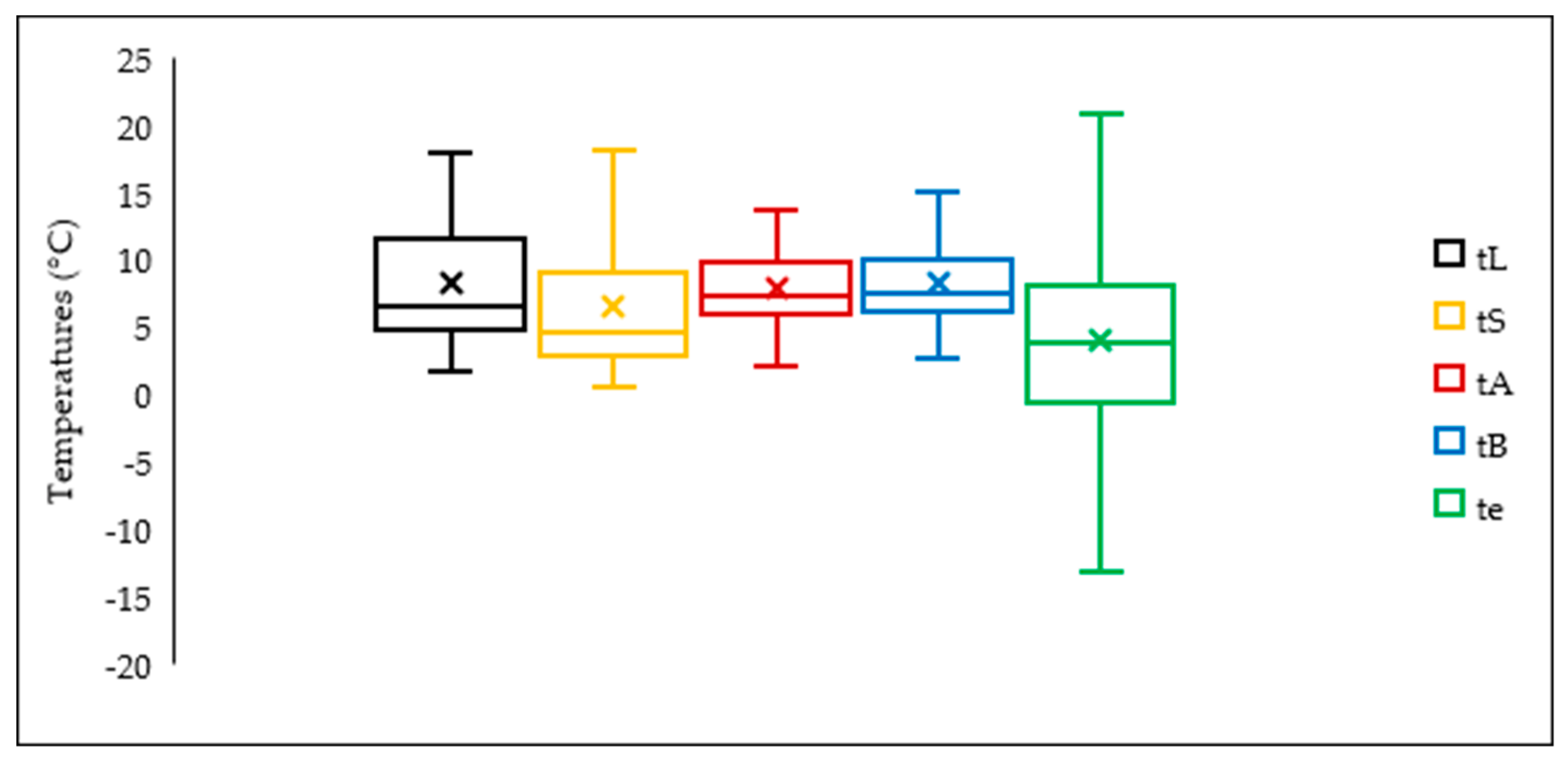
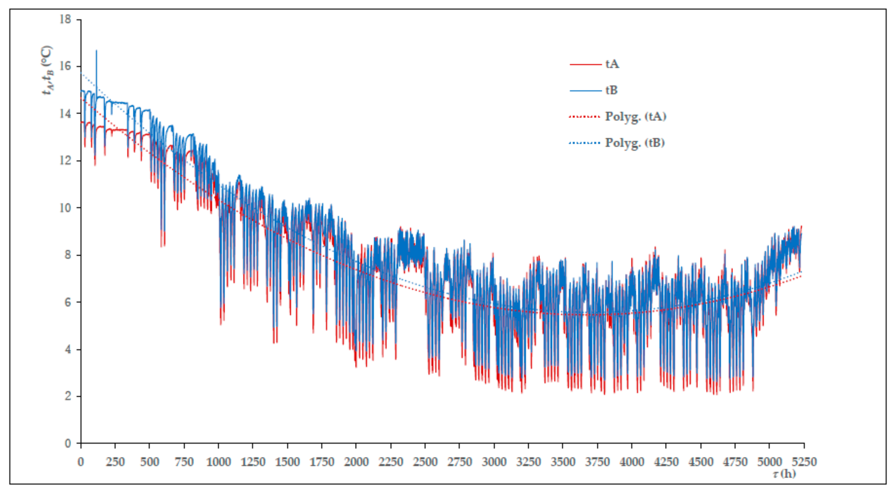
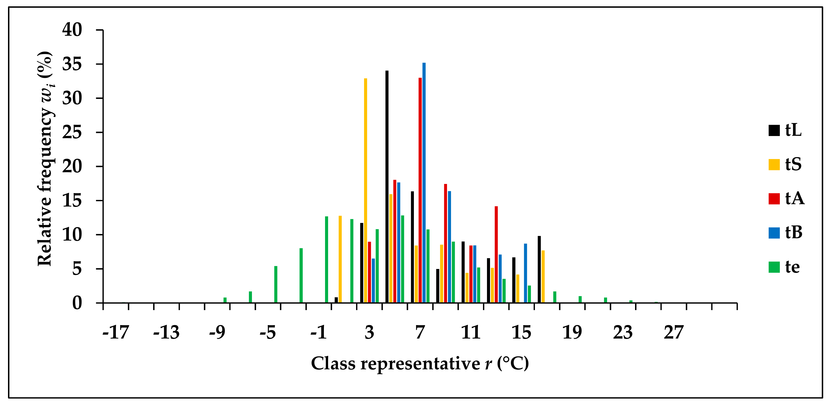
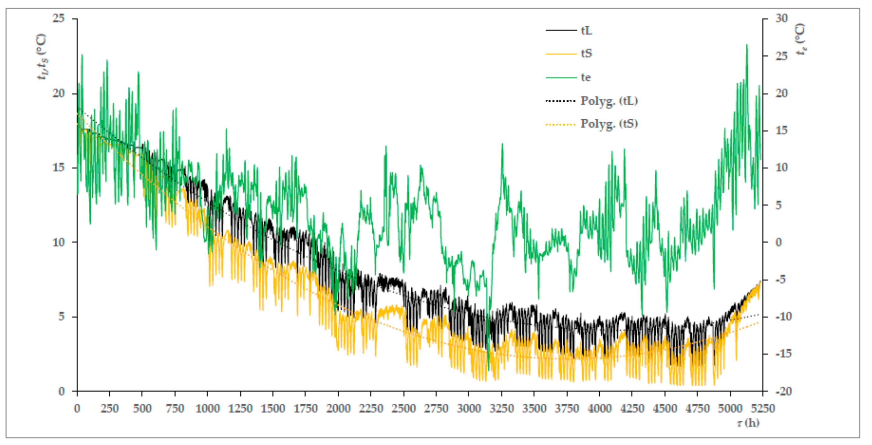
3.1. Temperatures of the Heat Transfer Fluids Supplied to the Heat Pump Evaporators

The histogram in Figure 1 displayed the distribution of the temperatures of the monitored low-temperature heat sources during the heating period (218 days, 5 232 monitored temperature values). The histogram allowed estimation of the highest temperature frequencies and temperature modes t ^ at intervals of 2 K.
The mode t ^ , the characteristic of distribution of the set of heat transfer fluid temperatures, expressed by the highest relative temperature frequency value, presented the most frequent occurrence of temperatures at a certain interval. The observed low-temperature heat sources were in the range of positive temperatures between 2.10–4.00 °C (class representative r = 3 °C) and 6.10–8.00 °C (r = 7 °C).
The VGHEs modes fell within the interval of 6.10–8.00 °C. The relative class frequencies of temperatures in this interval reached values wi = 35.19% and wi = 32.99% for type B and A, respectively. The interval of 2.10–4.00 °C was the lowest interval of the heat transfer fluid temperatures in VGHE. The relative class frequency of temperatures in this interval reached values wi = 6.50% (type B) and wi = 8.96% (type A).
The linear HGHE mode occurred in the range of 4.10–6.00 °C (r = 5 °C) with relative class frequency wi = 34.04% and the Slinky HGHE mode was in a lower temperature range of 2.10–4.00 °C with wi = 32.91%. The range of 0.10–2.00 °C (r = 1 °C) was the lowest range of temperatures in HGHEs in which there was wi = 0.84% (linear HGHE) and wi = 12.77% (Slinky HGHE).
The ambient air temperature mode was significantly affected by the higher air temperatures at the beginning and end of the heating season. It reached relative class frequency wi = 12.82% in the range of 4.10–6.00 °C. Ambient air temperatures occurred in a wide range between −17.90–(−16.00) °C (r = −17 °C) with wi = 0.11% and 26.10–28.00 °C (r = 27 °C), wi = 0.06%.
The higher frequency of the heat transfer fluid temperatures in the higher temperature ranges indicated the convenience of the low-temperature heat source.
The air temperature distribution at individual ranges can be considered as almost symmetrical, as again indicated by the temperature histogram in Figure 1, the coefficient of asymmetry being Ne = 0.77. The heat transfer fluid temperature distribution was left-skewed for both HGHEs and VGHEs, NL = 2.53, NS = 2.48, NA = 2.10, NB = 2.44.
The results of the statistical analysis of the heat transfer fluid temperature sets at the exchangers’ outlets and the ambient air temperatures were elaborated in Table 1 and the graph in Figure 2.
It follows from the above summary that the temperatures of the heat transfer fluid at VGHEs (tA, tB) reached the highest values for the averages t ¯ , minimum values tmin, medians t ˜ and lower quartiles Q1. The ranges Rv and variation coefficients S% reached also favourable low values. The double U-tube VGHE (B) proved to be slightly more favourable than a single U-tube VGHE (A) in terms of statistical analysis of the fluid temperatures. These results were confirmed by Zeng et al. [22].
The average temperature of the heat transfer fluid t ¯ from the linear HGHE was higher than that of Slinky HGHE and was almost identical to the average fluid temperature of the VGHE. The heat transfer fluid temperatures from the linear HGHE corresponded to the values presented by Kayaci and Demir [16]. The minimum tmin, median t ˜ , and lower quartile Q1 values were lower than for VGHE but higher than for Slinky HGHE. The interquartile range Q2–Q1 was the biggest of the monitored heat transfer fluids. The evaluation showed that the basic characteristics of the heat transfer fluid temperature sets with HGHE were less favourable than those with VGHE. This applied in particular to Slinky HGHE, where the minimum temperature tmin was close to 0 °C and the variation coefficient S% was higher. The distribution of temperatures of heat transfer fluids in HGHEs was closely related to the distribution of the ground mass temperatures presented in publication [31]. It follows from the above analysis and summary that the temperatures of the heat transfer fluids from VGHEs and HGHEs did not reached negative values in our validations.
The ambient temperature set was characterized by the lowest values of the average t ¯ , minimum tmin, median t ˜ , lower and upper quartile Q1 and Q2. It also proved the highest variation coefficient S%, the range Rv and the interquartile range Q2–Q1.
The graphs in Figure 3 and Figure 4 showed the temperatures of the heat transfer fluid flowing from the heat exchangers and the ambient air temperatures throughout the whole heating period. The reaction to the ambient air temperatures te was apparent from the course of the fluid temperatures. The temperatures of the heat transfer fluid in linear HGHE tL in Figure 3 were clearly higher than the temperatures of the heat transfer fluid of Slinky HGHE with the exception of the beginning and the end of the heating period. The quadratic equations of the trend line of the course of HGHEs fluid temperatures have the form of Equations (1) and (2). The curves matched well with the data as indicated by the determination coefficients R2.
t L = 8.80.10 7 τ 2 7.26.10 3 τ + 19.10   ( R 2   =   0.957 )
t S = 1.16.10 6 τ 2 8.74.10 3 τ + 18.60   ( R 2   =   0.952 )
Temperature differences of the heat transfer fluids tA and tB from VGHEs (Figure 4) were miner than from HGHEs. The quadratic equations of the trend lines of fluid temperature courses have the form of Equations (3) and (4). Determination coefficients R2 were lower. It follows from the temperature courses and Equations (3) and (4) that the heat transfer fluid temperatures from VGHE type B were slightly higher than from type A.
t A = 6.81.10 7 τ 2 5.01.10 3 τ + 14.70   ( R 2   =   0.774 )
t B = 7.41.10 7 τ 2 5.49.10 3 τ + 15.70   ( R 2   =   0.846 )
In Equations (1) to (4), τ (h) expresses the length of the heating period from its beginning, measured in hours. The output temperatures tA from VGHE type A were the same as those observed by Remiorz et al. [18] when verifying a similar type of VGHE.

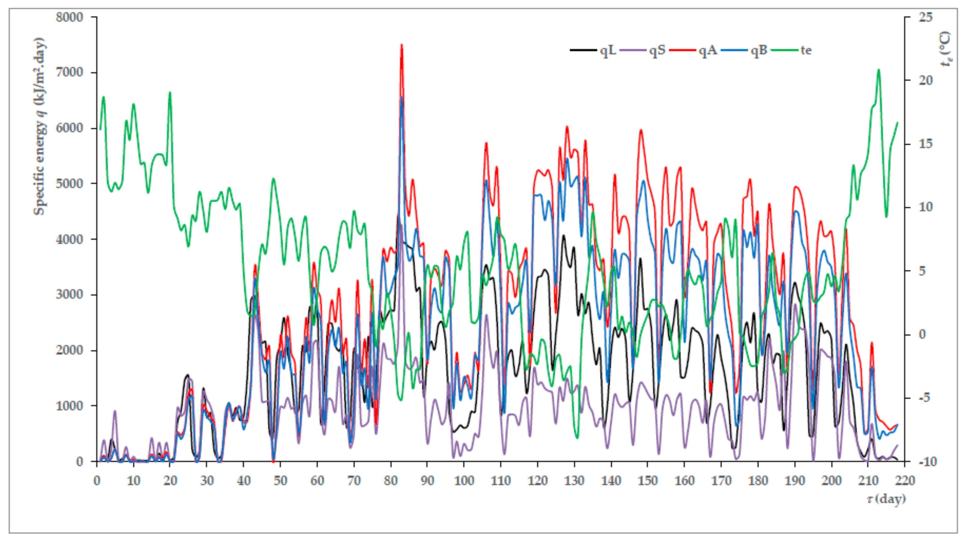
3.2. Specific Heat Outputs of Heat Exchangers and Specific Extracted Energies

The average and the maximum specific outputs in the heating period, qτ,a and qτ,max (W/m; W/m2), were presented in Table 2, converted to 1 m of pipe length and 1 m2 of heat exchanger’s surface. Furthermore, there is the average specific energy qa extracted by 1 m2 of the heat exchanger from the mass in 1 day of the heating period, the maximum daily and total amount of energy, qmax and qΣ, extracted by the heat exchanger from the mass in the heating period, as well as the total duration of the energy extraction by the heat exchanger τΣ during the heating period.
It followed from the above summary in Table 2 that the average and maximum specific output of VGHE type A was the highest of all the monitored low temperature sources. Banks [32] specified specific heat pump outputs for VGHE related to 1m length of the borehole in the range of 37 to 104 W, with an average of 67 W/m, the heat pump heating factor being 3.4. Hepbasli [33] specified the specific heat pump output of 61.4 W/m, the heating factor being 2.85. The measured average specific outputs of VGHEs extracted from the rock mass in the monitored heating period related to 1m length of the borehole, corresponded to the stated values. They were 15.07 ± 10.50 W/m (maximum 57.58 W/m) for type A and 19.63 ± 13.70 W/m (maximum 56.72 W/m) for type B. The average heat outputs of linear HGHE were higher than the Slinky HGHE outputs. Similar values of specific heat outputs were observed by Rosen et al. [34]. They presented the specific heat pump output of 13 W per 1m length of the exchanger tube (40 mm) with linear HGHE, heating factor being 3.5, and 7 W/m with Slinky HGHE. The specific heat outputs of HGHEs qτ,a (W/m) presented in Table 2 were near those values. Verda et al. [6] presented the value of 38W as the maximum of the extracted specific output of linear HGHE converted to 1 m2 of heat exchanger surface. In our verifications, the maximum specific output converted to heat exchanger surface area was only 18.43 W/m2 for linear HGHE and 100.08 W/m2 for Slinky HGHE. Lower specific outputs for VGHEs and HGHEs were caused by the way of operation of the production halls and the administrative building with interrupted operation and low demanded outputs for the heating system at the beginning and end of the heating period.
The specific power trend corresponded to the average specific energy extracted from the mass during the day. The total amount of energy transferred from the mass during the heating period was affected by the initial mass temperature and the duration of energy extraction. This was significantly shorter for Slinky HGHE. The recorded extraction energy values did not exceed the values recommended by Kyriakis and Michopoulus [35]. The course of the specific energies transferred from the mass with HGHE (qL, qS) and VGHE (qA, qB) during the heating period presented in Figure 5 confirmed the above results. As in the case of the temperatures of the heat transfer fluids, the graph in Figure 5 showed the relation of the extracted specific energy value qa and the ambient temperature te. This relation was also confirmed by the results of Todoran and Balan’s verifications [36].

3.3. Heat Resistances of the Heat Exchangers

The specific heat outputs and energies extracted from the mass were of relatively high explanatory power. The values of these parameters were influenced by the flow rate, the specific heat capacity, the density and the heating up of the heat transfer fluid in the exchanger. The specific heat capacity and the density were affected by the temperature of the heat transfer fluid. The verification results showed that the heat transfer fluid was heated the most in linear HGHE by a maximum of 5.86 K. When heating the heat transfer fluid from 0 to 6 °C, its density decreased by less than 1%, and the specific heat capacity of the fluid increased also by less than 1% [37]. Therefore, changes in thermal characteristics of the heat transfer fluid had only a marginal effect in this case. The increase in the heat transfer fluid temperature was influenced by the heat exchange surface of the exchanger, the flow of the heat transfer fluid and the temperature of the mass surrounding the heat exchanger. In terms of the possibility of evaluating the process of heat exchange between the mass and the heat transfer fluid of the monitored types of HGHEs and VGHEs, it is useful to express the specific heat resistance of the heat exchanger R (m2⋅K/W) by Equation (5), respecting the flow of the heat transfer fluid through the heat exchanger pipeline:
R = t r . m t a , h . t . f . q τ   ( m 2 · K / W )
In the Equation (5):
  • tr.m—temperature of the reference ground or rock mass (°C);
  • ta,h.t.f—average temperature of the heat transfer fluid (°C);
  • qτ—specific heat output converted to 1 m2 of heat exchanger surface (W/m2).
Higher R value indicated faster change in temperature of the heat transfer fluid, lower value reflected intensive process of heat transfer between the mass and the heat transfer fluid. Similar relation for the evaluation of the heat transfer process between the ground mass and the heat transfer fluid of Slinky HGHE exchangers was used by Zeng et al. [22] and by Bae et al. [23]. However, they related the specific resistance to 1 m length of the borehole with an exchanger. The calculated values of VGHEs specific resistances corresponded to the values presented in publications [22,23].
The following variables were listed in Table 3: heat exchanger surfaces of the exchanger pipelines S, average and maximum hourly heat transfer fluid flowrates, Vτ,a and Vτ,max, total volume of heat transfer fluid flowing through the heat exchangers during the heating period VΣ, and average and maximum specific heat exchanger resistances, Ra and Rmax.
Significantly lower thermal resistances at linear HGHE compared to Slinky HGHE are apparent from the above evaluation. The specific resistances differed not only due to the different configurations of the HGHEs pipeline, but also due to the different volume flows of the heat transfer fluids. The thermal resistances of linear HGHE were also lower than those of both types of VGHEs even though the volume flow in linear HGHE was smaller. Differences in thermal resistance between VGHEs were not significant.

4. Conclusions

The verification results showed that it was very difficult to specify the most advantageous low-temperature heat source fulfilling the requirements of the efficiency of heat pump operation. The results of measuring the temperatures of the heat transfer fluids and the thermal resistances of the heat exchangers were considered dominant in the assessment of these energy sources.
The average temperature of the heat transfer fluid t ¯ in VGHE type B, the minimum temperature tmin, median t ˜ and temperature quartiles Q1, Q2 were higher than in VGHE type A. Also, the relative frequency of the temperature occurrence in the mode of fluid temperature set distribution of 6.10–8.00 °C was higher by 2.20% than in the temperature set of VGHE type A. However, the temperature differences of the fluids were not significant as followed from the course of the average hourly temperature of the heat transfer fluid in Figure 4 and from Equations (3) and (4). The average thermal resistances of both VGHEs were comparable; the maximum resistances differed in accordance with the results reported by Zeng et al. [22]. VGHE type A had higher average specific output qτ,a by 22.89% (10.17 W/ m2) at a lower average volume flow of the heat transfer fluid. This analysis indicated that VGHE type A can be considered more advantageous than VGHE type B.
The modus for linear HGHE 4.10–6.00 °C was higher than for Slinky HGHE 2.10–4.00 °C. The fluid temperature differences were significantly greater between the HGHEs (in favour of the linear HGHE) than between the two types of VGHEs as is apparent from Equations (1) and (2) as well as from the average hourly temperatures of the heat transfer fluid shown in Figure 3. The thermal resistance of linear HGHE amounted to 50% of Slinky HGHE thermal resistance value. Linear HGHE had higher average specific output qτ,a than Slinky HGHE by 17.26% (5.76 W/ m2) at higher average volume flow rate of the heat transfer fluid. Due to the temperatures of the heat transfer fluids, the specific outputs and the specific thermal resistances of linear HGHE reached more favourable values, this seemed to be the more advantageous exchanger.
Comparison of linear HGHE and VGHE type A indicated that the average temperature of the heat transfer fluid t ¯ was higher by 4.50% (0.35 K) at linear HGHE, but the mode of VGHE type A occurred in higher temperature interval than the mode of linear HGHE. The thermal resistance of linear HGHE was lower than that of VGHE type A by 22.22% (0.02 m2⋅K/W). At the heat exchange surface S lower by 31.52% (13.07 m2) and the average volume flow of the heat transfer fluid Vτ,a higher by 10.64% (0.05 m3/h), the average specific output of VGHE type A was higher by 53.22% (20.83 W/m2) than that of linear HGHE. The results of the analysis indicated that VGHE type A appears to be more advantageous low-temperature source in this comparison. In this case, an important role in choosing a low temperature source is the area of land on which the installation of the source can be realized. The installation of linear HGHEs is certainly less demanding for investment cost.
The use of ambient air as a low-temperature heat pump source was considered to be the least advantageous in terms of its temperature parameters.
The mentioned analyses were based only on the results of monitoring the low-temperature heat pump sources during the heating period 2012/2013. The aim of our further work will be to verify the validity of the results in other climatic conditions, especially at lower ambient air temperatures and for longer heating periods.

Author Contributions

All authors contribute equally to this paper.

Funding

This research received no external funding.

Acknowledgments

Acknowledgement belongs to the management of the company Veskom, s.r.o. (Prague, Czech Republic) which implemented the experimental facility within its own-account and was very receptive in preparing conditions for the verification of these energetic systems.

Conflicts of Interest

The authors declare no conflict of interest.

Nomenclature

ASingle U-tube VGHE
BDouble U-tube VGHE
LLinear HGHE
HGHEHorizontal Ground Heat Exchanger
HVACHeating, Ventilation and Air Conditioning
NCoefficient of asymmetry of temperature distribution (-)
Q1Lower quartile of temperature distribution (°C)
Q2Upper quartile of temperature distribution (°C)
PCMPhase changing materials
RThermal resistance of heat exchanger (K.m2/W)
R2Determination coefficient (-)
RvTemperature range (K)
SSlinky HGHE
S2Temperature variance (K2)
S%Variation coefficient of temperature distribution (%)
VτVolume flow of heat transfer fluid (m3/h)
VGHEVertical Ground Heat Exchanger
qτSpecific heat output of heat exchanger W/m,W/m2
rCategory representative of temperature interval (°C)
tTemperature (°C)
t ˜ Median of temperatures (°C)
t ¯ Mode of temperatures (°C)
t ^ Reference temperature of the ground or rock mass (°C)
tr.mAverage temperature of heat transfer fluid (°C)
ta,h.t.f.Volumetric moisture (%)
vRelative frequency of temperatures (%)
wiLength of heating period (h)
τSingle U-tube VGHE
Indexes
ALinear HGHE
BSlinky HGHE
LAverage value
SAmbient air temperature
aMaximum value
eMinimal value
maxSummative value
minSingle U-tube VGHE
Double U-tube VGHE

References

  1. Peréz-Lombard, L.; Ortiz, J.; Pout, C. A review on buildings energy consumption information. Energy Build. 2008, 40, 394–398. [Google Scholar] [CrossRef]
  2. Stefansson, V. The renewability of geothermal energy. In Proceedings of the World Geothermal Congress 2000, Tohoku, Japan, 28 May–10 June 2000; pp. 883–888. [Google Scholar]
  3. Stefansson, V.; Axelsson, G. Sustainable utilization of geothermal resources through stepwise development. In Proceedings of the World Geothermal Congress 2005, Antalya, Turkey, 24–29 April 2005; pp. 1–8. [Google Scholar]
  4. Wei, W.; Baolong, W.; Tian, Y.; Wenxing, S.; Yiating, L. A potential solution for thermal imbalance of ground source heat pump systems in cold regions: Ground source absorption heat pump. Renew. Energy 2013, 59, 39–48. [Google Scholar] [CrossRef]
  5. Mensah, K.; Jang, Y.-S.; Choi, J.M. Assessment of design strategies in a ground source heat pump system. Energy Build. 2017, 138, 301–308. [Google Scholar] [CrossRef]
  6. Verda, V.; Cosentino, S.; Russo, S.L.; Sciacovelli, A. Second law analysis of horizontal geothermal heat pump systems. Energy Build. 2016, 124, 236–240. [Google Scholar] [CrossRef]
  7. Choi, W.; Ooka, R.; Nam, Y. Impact of long-term operation of ground-source heat pump on subsurface thermal state in urban areas. Sustain. Cities Soc. 2018, 38, 429–439. [Google Scholar] [CrossRef]
  8. Rybach, L. Geothermal energy: sustanability and the environment. Geothermics 2003, 32, 463–470. [Google Scholar] [CrossRef]
  9. Larwa, B. Heat transfer model to predict temperature distribution in tha ground. Energies 2019, 12, 25. [Google Scholar] [CrossRef]
  10. Gultekin, A.; Aydin, M.; Sisman, A. Thermal performance analysis of multiple borehole heat exchangers. Energy Convers. Manag. 2016, 122, 544–551. [Google Scholar] [CrossRef]
  11. Sivasakthivel, T.; Murugesan, K.; Thomas, H.R. Optimization of operating parameters of ground source heat pump system for space heating and cooling by Taguchi method and utility concept. Appl. Energy 2014, 116, 76–85. [Google Scholar] [CrossRef]
  12. Zarrella, A.; De Carli, M. Heat transfer of short helical borehole heat exchnagers. Appl. Energy 2013, 102, 1477–1491. [Google Scholar] [CrossRef]
  13. Hepburn, B.D.P.; Sedighi, M.; Thomas, H.R. Field-scale monitoring of a horizontal ground source heat system. Geothermics 2016, 61, 86–103. [Google Scholar] [CrossRef]
  14. Michopoulos, A.; Kyriakis, N. Predicting the fluid temperature at the exit of the vertical ground heat exchangers. Appl. Energy 2009, 86, 2065–2070. [Google Scholar] [CrossRef]
  15. Go, G.-H.; Lee, S.-R.; Nikhil, N.V.; Yoon, S. A new performance evaluation algorithm for horizontal GCHPs (ground coupled heat pump systems) that considers rainfall infiltration. Energy 2015, 83, 766–777. [Google Scholar] [CrossRef]
  16. Kayaci, N.; Demir, H. Long time performance analysis of ground source heat pump for space heating and cooling applications based on thermo-economic optimization criteria. Energy Build. 2018, 163, 121–139. [Google Scholar] [CrossRef]
  17. Ren, C.H.; Deng, Y.; Cao, S.-J. Evaluation of polyethylene and steel heat exchangers of ground source heat pump systems based on seasonal performance comparison and life cycle assessment. Energy 2018, 162, 54–64. [Google Scholar] [CrossRef]
  18. Remiorz, L.; Hanuszkiewicz-Drapala, M. Cumulated energy consumption in a heat pump system using a U-tube ground heat exchanger in a moderate climate. Energy Build. 2015, 96, 118–127. [Google Scholar] [CrossRef]
  19. Fujii, H.; Nishi, K.; Komaniwa, Y.; Chou, N. Numerical modeling of slinky-coil horizontal ground heat exchangers. Geothermics 2012, 41, 55–62. [Google Scholar] [CrossRef]
  20. Dehghan, B.; Sisman, A.; Aydin, M. Parametric investigation of helical ground heat exchangers for heat pump applications. Energy Build. 2016, 127, 999–1007. [Google Scholar] [CrossRef]
  21. Lee, C.H.; You, J.; Park, H. In-situ response test of various borehole depths and heat injection rates at standing column well geothermal heat exchanger systems. Energy Build. 2018, 172, 201–208. [Google Scholar] [CrossRef]
  22. Zeng, H.; Diao, N.; Fang, Z. Heat transfer analysis of boreholes in vertical ground heat exchangers. Int. J. Heat Mass Transf. 2003, 46, 4467–4481. [Google Scholar] [CrossRef]
  23. Bae, S.M.; Nam, Y.; Choi, J.M.; Lee, K.H.; Choi, J.S. Analysis on Thermal Performance of Ground Heat Exchanger According to Design Type Based on Thermal Response Test. Energies 2019, 12, 651. [Google Scholar] [CrossRef]
  24. Neuberger, P.; Adamovský, R.; Šeďová, M. Temperatures and Heat Flows in a Soil Enclosing a Slinky Horizontal Heat Exchanger. Energies 2014, 7, 972–987. [Google Scholar] [CrossRef]
  25. Pauli, P.; Neuberger, P.; Adamovský, R. Monitoring and Analysing Changes in Temperature and Energy in the Ground with Installed Horizontal Ground Heat Exchangers. Energies 2016, 9, 555. [Google Scholar] [CrossRef]
  26. Bottarelli, M.; Bortoloni, M.; Su, Y. Heat transfer analysis of underground thermal energy storage in shallow trenches filled with encapsulated phase change materials. Appl. Therm. Eng. 2015, 90, 1044–1051. [Google Scholar] [CrossRef]
  27. Dai, L.; Li, S.; DuanMu, L.; Li, X.; Shang, Y.; Dong, M. Experimental performance analysis of solar assited ground source heat pump system under diferent heating operation modes. Appl. Therm. Eng. 2015, 75, 325–333. [Google Scholar] [CrossRef]
  28. Li, W.; Li, X.; Wang, Y.; Tu, J. An integrated predictive model of the long-term performance of ground source heat pump (GSHP) systems. Energy Build. 2018, 159, 309–318. [Google Scholar] [CrossRef]
  29. You, T.; Wu, W.; Shi, W.; Wang, B.; Li, X. An overview of the problems and solution of soil thermal imbalance of ground-coupled heat pumps in cold regions. Appl. Energy 2016, 177, 515–536. [Google Scholar] [CrossRef]
  30. Guo, X.; Hendel, M. Urban water networks as a an alternative source for district heating and emergency heat-wave cooling. Energy 2018, 145, 79–87. [Google Scholar] [CrossRef]
  31. Neuberger, P.; Adamovský, R. Analysis of the Potential of Low-Temperature Heat Pump Energy Sources. Energies 2017, 10, 1922. [Google Scholar] [CrossRef]
  32. Banks, D. An Introduction to Thermogeology: Ground Source Heating and Cooling, 2nd ed.; JohnWiley & Sons: Chichester, UK, 2012; p. 546. ISBN 978-0-470-67034-7. [Google Scholar]
  33. Hepbasli, A. Thermodynamic analysis of a ground-source heat pump systém for district heating. Int. J. Energy Res. 2005, 29, 671–687. [Google Scholar] [CrossRef]
  34. Rosén, B.; Gabrielsson, A.; Hellström, G.; Nilsson, G. System för Värme och kyla ur Mark—Demonstrationsobjekt över Jordvärmeanläggningar; Statens Geotekniska Institut: Linköping, Sweden, 2006; (In Swedish). Available online: http://swedgeo.diva-portal.org/smash/get/diva2:1300458/FULLTEXT01.pdf (accessed on 11 April 2019).
  35. Kyriakis, N.; Michopoulos, F. On the maximum thermal load of ground heat exchangers. Energy Build. 2006, 38, 25–29. [Google Scholar] [CrossRef]
  36. Todoran, T.P.; Balan, M.C. Long term behavior of a geothermal heat pump with oversized horizontal collector. Energy Build. 2016, 133, 799–809. [Google Scholar] [CrossRef]
  37. The Engineering ToolBox: Ethanol Freeze Protected Water Solutions. Available online: https://www.engineeringtoolbox.com/ethanol-water-d_989.html (accessed on 7 February 2015).
Figure 1. Frequencies of heat transfer fluid temperatures (tL, tS, tA, tB) and ambient air temperatures (te) during heating period.
Energies 12 01853 g001
Figure 2. Box plot of heat transfer fluid temperatures (tL, tS, tA, tB) and ambient air temperatures (te) during the heating period.
Energies 12 01853 g002
Figure 3. Course of average hourly temperatures of heat transfer fluids from linear (tL) and Slinky HGHEs (tS) and of ambient air (te).
Energies 12 01853 g003
Figure 4. Course of average hourly temperatures of heat transfer fluids from single U-tube (tA) and double U-tube VGHEs (tB ).
Energies 12 01853 g004
Figure 5. Specific energy extracted by HGHEs (qL qS ), VGHEs (qA qB ) and ambient air temperature (te) during heating period.
Energies 12 01853 g005
Table 1. Quantile characteristics of the heat transfer fluid temperature sets at the exchanger’s outlets and the ambient air temperatures.
HeaderHGHEVGHEAmbient Air
LSABe
Average t ¯ (°C)8.13 ± 4.506.36 ± 4.797.78 ± 2.948.13 ± 3.123.98 ± 6.21
Minimum tmin (°C)1.670.392.082.64−17.23
Maximum tmax (°C)17.8217.9713.6616.6926.57
Median t ˜ (°C)6.394.597.287.353.69
Lower quartile Q14.632.785.876.04−0.65
Upper quartile Q211.408.929.679.097.92
Variance S2 (K2)20.2322.958.659.7138.59
Variation coefficient S% (%)55.3475.3537.7938.30155.94
Range Rv (K)16.1517.5911.5814.0543.79
Interquartile range Q1Q2 (K)6.776.153.803.868.56
Table 2. Specific heat outputs of heat exchangers and specific energies extracted from the ground and rock mass.
ParameterHGHEVGHE
LSAB
qτ,a
(W/m)
4.92 ± 3.603.35 ± 2.427.53 ± 5.254.90 ± 3.42
qτ,max
(W/m)
15.2512.4829.2814.18
qτ,a
(W/m2)
39.14 ± 28.6733.38 ± 24.1159.97 ± 41.8048.80 ± 34.08
qτ,max
(W/m2)
121.42124.20233.08141.05
qa
(kJ/m2·day)
1614.15 ± 1076.40938.31 ± 677.702723.40 ± 1785.582353.59 ± 1540.89
qmax
(kJ/m2·day)
4407.734258.867495.076564.86
qΣ
(MJ/m2)
351.88204.55593.70513.08
τΣ
(h)
2497170327502920
Table 3. Flow rates of heat transfer fluid and specific thermal resistances of heat exchangers.
ParameterHGHEVGHE
LSAB
S
(m2)
41.4720.1128.4045.44
Vτ,a
(m3/h)
0.47 ± 0.220.35 ± 0.120.52 ± 0.260.61 ± 0.31
Vτ,max
(m3/h)
0.890.721.031.27
VΣ
(m3)
1 183.70592.821 435.961 787.94
Ra
(m2⋅K/W)
0.07 ± 0.020.14 ± 0.060.09 ± 0.030.11 ± 0.04
Rmax
(m2·K/W)
0.130.380.160.23

