An Energy-Saving Optimization Method of Dynamic Scheduling for Disassembly Line


Abstract
:1. Introduction
2. Literature Review
2.1. Disassembly Line Evaluation and Optimization
2.2. Energy Consumption Modeling and Evaluation
3. Description of the Problem
4. Modeling of Energy Consumption in Disassembly Line
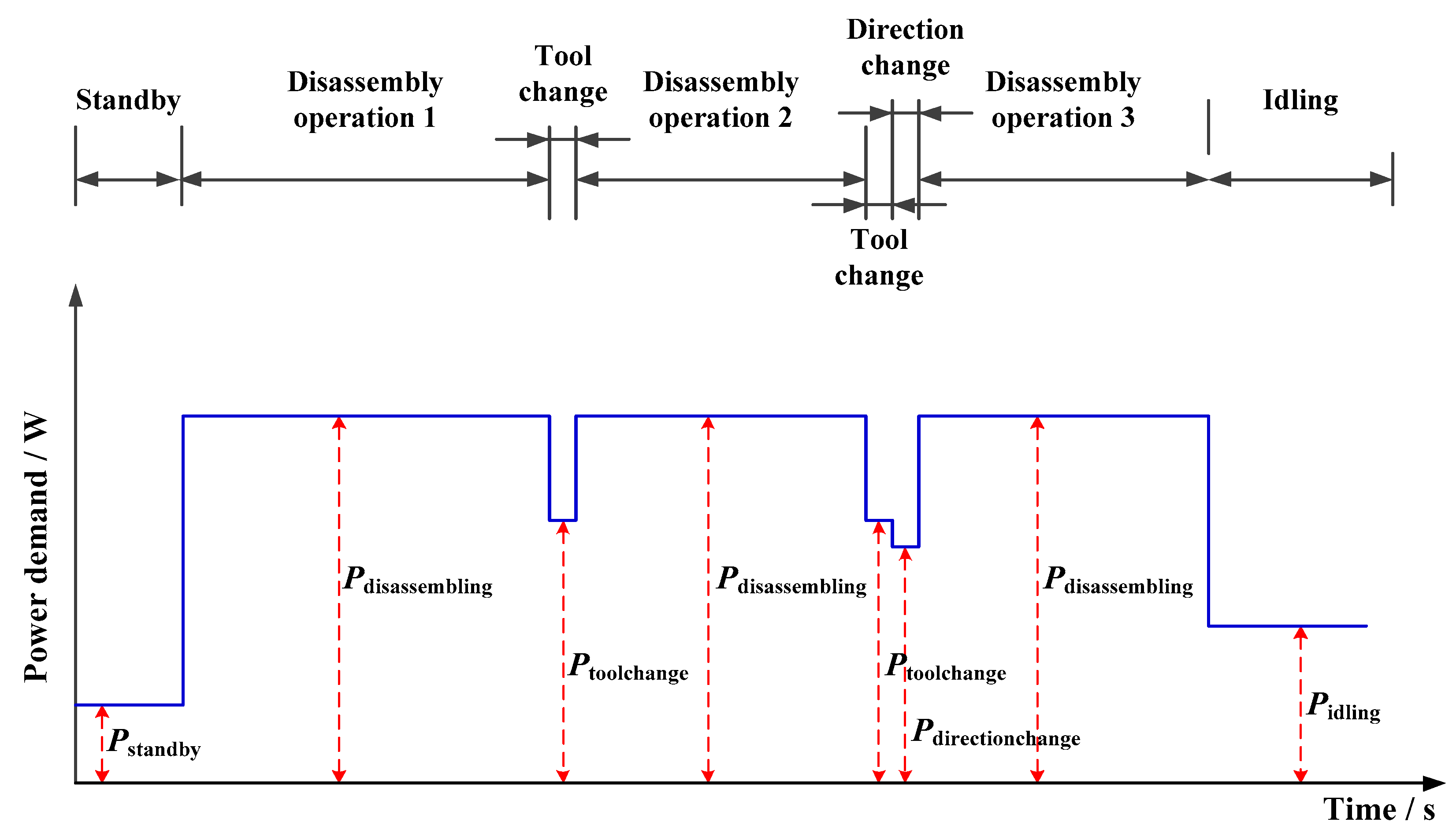
4.1. Analysis of Energy Consumption in Disassembling Process
4.2. Model of Standby Energy Consumption
4.3. Model of Idling Energy Consumption
4.4. Model of Disassembling Energy Consumption
4.5. Model of Direction Changing Energy Consumption
4.6. Model of Tool Changing Energy Consumption
5. Modeling of the DLBP with Energy Saving Consideration
- A disassembly line is used to disassemble a single product type.
- The supply of the EOL product is infinite.
- The workstations are capable to process only one disassembly operation at a time.
- Each component should be assigned to one workstation.
- The time of all the components assigned to a workstation must not exceed the cycle time CT.
- The precedence relationships among the components must be satisfied.
- Determining the number of workstations in order to minimize the total cost.
- Determining the assignment of each disassembly operation and ensuring that the working load of each workstation is similar.
- Finding the sequence of disassembly operations assigned to each workstation with the minimal total energy consumption.
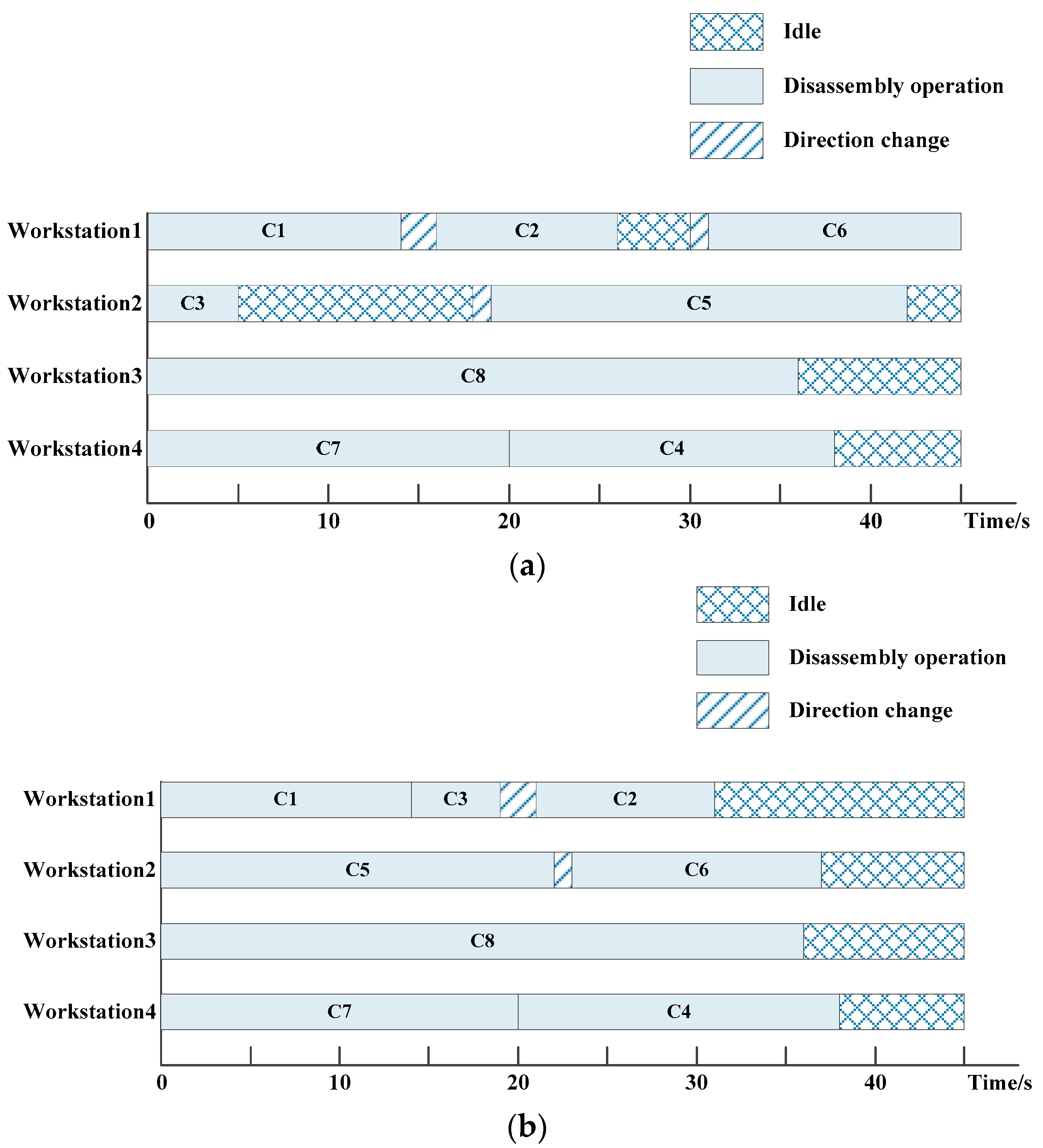
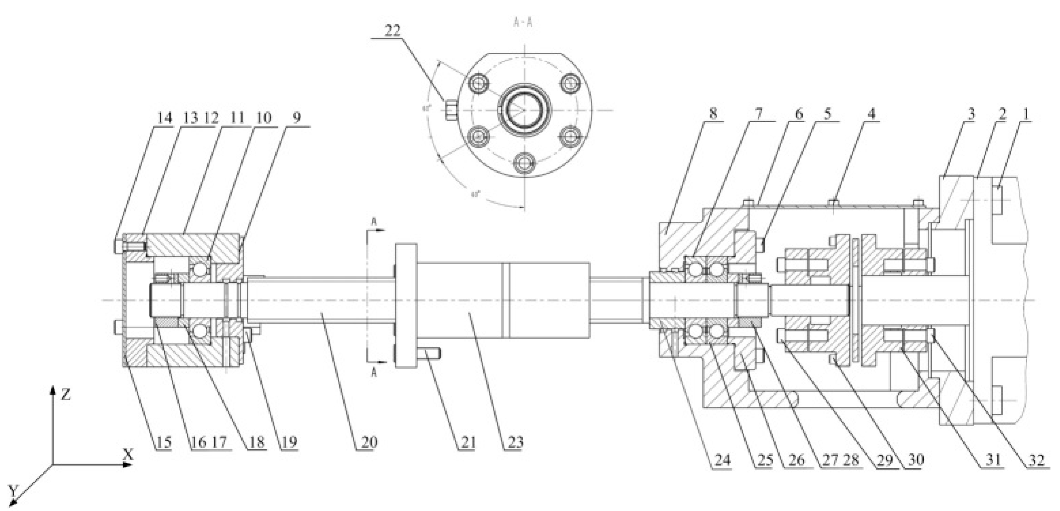
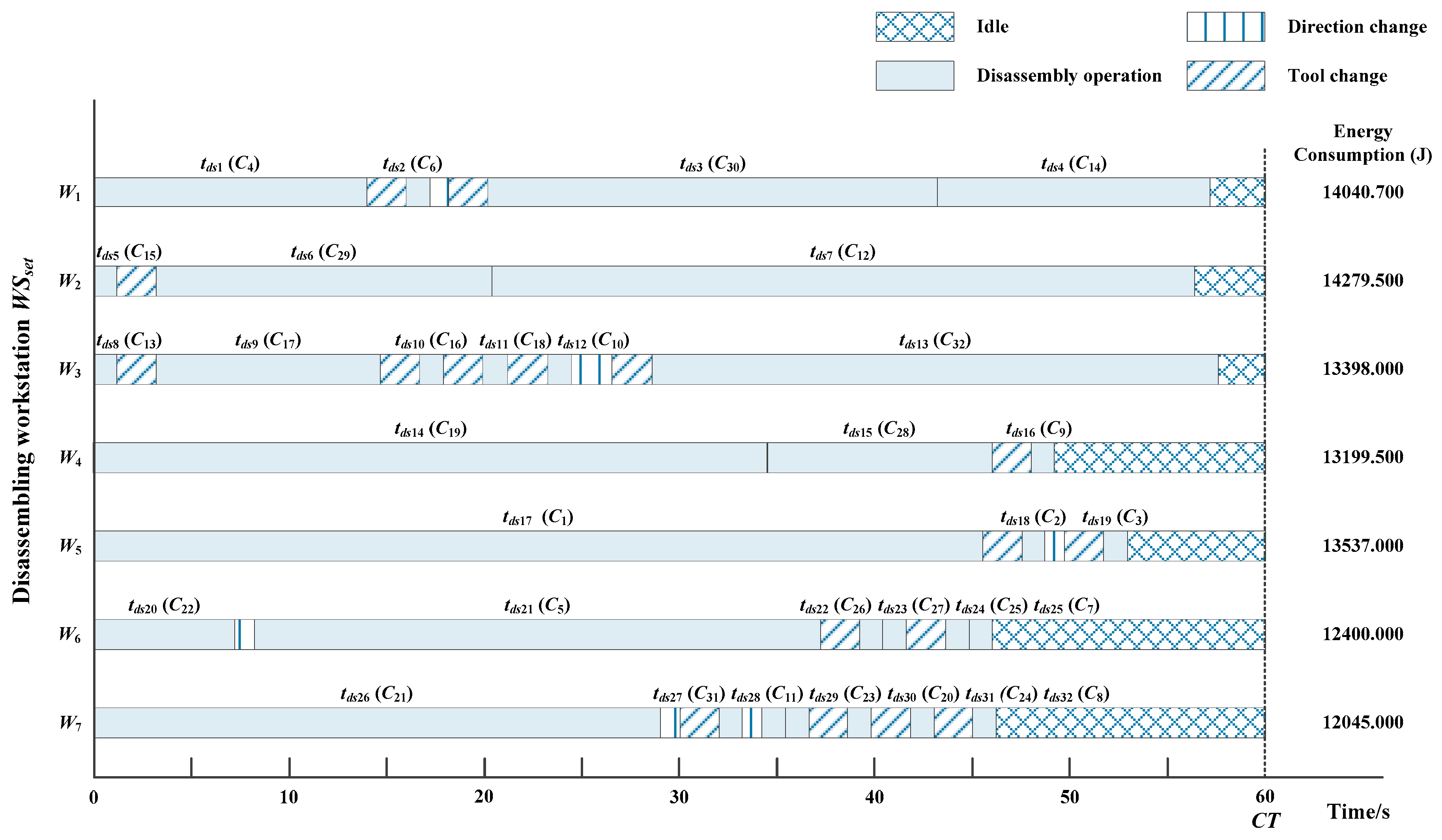
6. Case Study
6.1. Results
6.2. Discussion
7. Conclusions
Author Contributions
Funding
Conflicts of Interest
Nomenclature
| CT | The cycle time. |
| Ei | Energy consumption of Wi. |
| Esbi | Energy consumption of the standby of Wi. |
| Eidlei | Energy consumption of the idling of the Wi. |
| Edsij | Energy consumption of the disassembling of Cj in Wi. |
| Edcij | Energy consumption of the direction changing of Cj in Wi. |
| Etcij | Energy consumption of the tool changing of Cj in Wi. |
| EMTCi | Energy consumption of the manual tool change of Wi. |
| EATCij | Energy consumption of the automatic tool change of Cj in Wi. |
| nnej | The normalized execution time of Cj. |
| ndcj | The times of direction changing (1 if the included angle of Cj and Ck is ±90°; 2 if the included angle is ±180°; 0 otherwise). |
| P0i | The idle power of Wi. |
| Pdci | The direction changing power of Wi. |
| Pdsi | The disassembling power of Wi. |
| Psbij | The standby power of Wi. |
| Ptci | The tool changing power of Wi. |
| tloading | The average automatic loading time. |
| tunloading | The average automatic unloading time. |
| tclamingi | The average clamping time of one EOL product of Wi. |
| tidlei | The idle time for the next operation of Wi. |
| tndj | The normalized disassembly time of Cj. |
| tdc0 | The average direction changing time. |
| tMTC | The average manual tool changing time. |
| tfix | The fixed time during one tool change cycle. |
| ttc0 | The time required for the magazine to rotate through one station. |
| tdai | The additional time of Wi corresponding to precedence constraints. |
| tdci | The direction changing time of Wi. |
| ttci | The tool changing time of Wi. |
| ∆posj | The number of stations rotated from the tool of Cj to that of the next. |
| M | The number of components. |
| N | The number of workstations. |
| i | Workstation index, i = 1, 2, …, N. |
| j,l | Component index, j, l = 1, 2, …, M. |
| k | Disassembly operation index, k = 1, 2, …, M. |
| xjk | Binary variable (1 if Cj is removed as the k-th disassembly operation in the disassembly sequence; 0 otherwise). |
| yik | Binary variable (1 if the k-th disassembly operation is assigned to Wi; 0 otherwise). |
| pljl | Binary variable (1 if disassembly of Cj can precede disassembly of Cl). |
| dcjl | Binary variable (1, if the direction of disassembly operations of Cj and Cl are different; 0 otherwise). |
| tcjl | Binary variable (1, if the disassembly operations of Cj and Cl use different tools; 0 otherwise). |
References
- Salama, W. Design of concrete buildings for disassembly: An explorative review. Int. J. Sustain. Built Environ. 2017. [Google Scholar] [CrossRef]
- Wang, Q.; Liu, F.; Li, C. An integrated method for assessing the energy efficiency of machining workshop. J. Clean. Prod. 2013, 52, 122–133. [Google Scholar] [CrossRef]
- Shrouf, F.; Ordieres-Meré, J.; García-Sánchez, A.; Ortega-Mier, M. Optimizing the production scheduling of a single machine to minimize total energy consumption costs. J. Clean. Prod. 2014, 67, 197–207. [Google Scholar] [CrossRef]
- Cai, W.; Liu, F.; Zhou, X.; Xie, J. Fine energy consumption allowance of workpieces in the mechanical manufacturing industry. Energy 2016, 114, 623–633. [Google Scholar] [CrossRef]
- May, G.; Stahl, B.; Taisch, M.; Prabhu, V. Multi-objective genetic algorithm for energy-efficient job shop scheduling. Int. J. Prod. Res. 2015, 53, 7071–7089. [Google Scholar] [CrossRef]
- He, Y.; Li, Y.; Wu, T.; Sutherland, J.W. An energy-responsive optimization method for machine tool selection and operation sequence in flexible machining job shops. J. Clean. Prod. 2015, 87, 245–254. [Google Scholar] [CrossRef]
- Salido, M.A.; Escamilla, J.; Giret, A.; Barber, F. A genetic algorithm for energy-efficiency in job-shop scheduling. Int. J. Adv. Manuf. Technol. 2016, 85, 1303–1314. [Google Scholar] [CrossRef]
- ElMaraghy, H.A.; Youssef, A.M.; Marzouk, A.M.; ElMaraghy, W.H. Energy use analysis and local benchmarking of manufacturing lines. J. Clean. Prod. 2016, 163, 36–48. [Google Scholar] [CrossRef]
- Paksoy, T.; Güngör, A.; Özceylan, E.; Hancilar, A. Mixed model disassembly line balancing problem with fuzzy goals. Int. J. Prod. Res. 2013, 51, 6082–6096. [Google Scholar] [CrossRef]
- Liu, F.; Xie, J.; Liu, S. A method for predicting the energy consumption of the main driving system of a machine tool in a machining process. J. Clean. Prod. 2015, 105, 171–177. [Google Scholar] [CrossRef]
- Gungor, A.; Gupta, S.M. Disassembly line in product recovery. Int. J. Prod. Res. 2002, 40, 2569–2589. [Google Scholar] [CrossRef]
- Bentaha, M.L.; Battaïa, O.; Dolgui, A. Disassembly line balancing problem with fixed number of workstations under uncertainty. IFAC Proc. Vol. 2014, 47, 3522–3526. [Google Scholar] [CrossRef]
- Tang, Y.; Zhou, M.C. A systematic approach to design and operation of disassembly lines. IEEE Tran. Autom. Sci. Eng. 2006, 3, 324–329. [Google Scholar] [CrossRef]
- Altekin, F.T.; Akkan, C. Task-failure-driven rebalancing of disassembly lines. Int. J. Prod. Res. 2012, 50, 4955–4976. [Google Scholar] [CrossRef]
- Aydemir-Karadag, A.; Turkbey, O. Multi-objective optimization of stochastic disassembly line balancing with station paralleling. Comput. Ind. Eng. 2013, 65, 413–425. [Google Scholar] [CrossRef]
- Kalayci, C.B.; Polat, O.; Gupta, S.M. A variable neighborhood search algorithm for disassembly lines. Int. J. Adv. Manuf. Technol. 2015, 26, 182–194. [Google Scholar]
- Kalaycilar, E.G.; Azizoglu, M.; Yeralan, S. A disassembly line balancing problem with fixed number of workstations. Eur. J. Oper. Res. 2016, 249, 592–602. [Google Scholar] [CrossRef]
- Kalayci, C.B.; Gupta, S.M. Artificial bee colony algorithm for solving sequence-dependent disassembly line balancing problem. Expert Syst. Appl. 2013, 40, 7231–7241. [Google Scholar] [CrossRef]
- Kalayci, C.B.; Polat, O.; Gupta, S.M. A hybrid genetic algorithm for sequence-dependent disassembly line balancing problem. Ann. Oper. Res. 2016, 242, 321–354. [Google Scholar] [CrossRef]
- Mete, S.; Çil, Z.A.; Ozceylan, E. A heuristic approach for joint design of assembly and disassembly line balancing problem. In Proceedings of the 8th International Conference on Information Technology (ICIT), Amman, Jordan, 17–18 May 2017; pp. 418–423. [Google Scholar]
- Liu, J.; Wang, S.W. A proposed multi-objective optimization model for sequence-dependent disassembly line balancing problem. In Proceedings of the 3rd International Conference on Information Management (ICIM), Chengdu, China, 21–23 April 2017; pp. 421–425. [Google Scholar]
- Pistolesi, F.; Lazzerini, B.; Mura, M.D.; Dini, G. EMOGA: A hybrid genetic algorithm with extremal optimization core for multiobjective disassembly line balancing. IEEE Tran. Ind. Inform. 2017, 14, 1089–1098. [Google Scholar] [CrossRef]
- Gutowski, T.; Dahmus, J.; Thiriez, A. Electrical energy requirements for manufacturing processes. In Proceedings of the 13th CIRP International Conference on Life Cycle Engineering, Katholieke Universiteit Leuven, Brussels, Belguim, 31 May—2 June 2006; Volume 31, pp. 623–638. [Google Scholar]
- Chen, G.; Zhang, L.; Arinez, J.; Biller, S. Energy-efficient production systems through schedule-based operations. IEEE Trans. Autom. Sci. 2013, 10, 27–37. [Google Scholar] [CrossRef]
- Li, Y.; He, Y.; Wang, Y.; Wang, Y.; Yan, P.; Lin, S. A modeling method for hybrid energy behaviors in flexible machining systems. Energy 2015, 86, 164–174. [Google Scholar] [CrossRef]
- Mokhtari, H.; Hasani, A. An energy-efficient multi-objective optimization for flexible job-shop scheduling problem. Comput. Chem. Eng. 2017, 104, 339–352. [Google Scholar] [CrossRef]
- Yildirim, M.B.; Mouzon, G. Single-machine sustainable production planning to minimize total energy consumption and total completion time using a multiple objective genetic algorithm. IEEE Trans. Eng. Manag. 2012, 59, 585–597. [Google Scholar] [CrossRef]
- Dai, M.; Tang, D.; Giret, A.; Salido, M.A.; Li, W.D. Energy-efficient scheduling for a flexible flow shop using an improved genetic-simulated annealing algorithm. Robot. Comput.-Integr. Manuf. 2013, 29, 418–429. [Google Scholar] [CrossRef]
- Liu, Y.; Dong, H.; Lohse, N.; Petrovic, S.; Gindy, N. An investigation into minimising total energy consumption and total weighted tardiness in job shops. J. Clean. Prod. 2014, 65, 87–96. [Google Scholar] [CrossRef]
- Tang, D.; Dai, M.; Salido, M.A.; Giret, A. Energy-efficient dynamic scheduling for a flexible flow shop using an improved particle swarm optimization. Comput. Ind. 2016, 81, 82–95. [Google Scholar] [CrossRef]
- Mouzon, G.; Yildirim, M.B.; Twomey, J. Operational methods for minimization of energy consumption of manufacturing equipment. Int. J. Prod. Res. 2007, 45, 4247–4271. [Google Scholar] [CrossRef]
- Dowie, T.; Kelly, P. Estimation of Disassembly Times; Report DDR/TR15; Manchester Metropolitan University: Manchester, UK, 1994. [Google Scholar]
- Lv, J.; Tang, R.; Jia, S. Therblig-based energy supply modeling of computer numerical control machine tools. J. Clean. Prod. 2014, 65, 168–177. [Google Scholar] [CrossRef]
- Ding, L.P.; Feng, Y.X.; Tan, J.R.; Gao, Y.C. A new multi-objective ant colony algorithm for solving the disassembly line balancing problem. Int. J. Adv. Manuf. Technol. 2010, 48, 761–771. [Google Scholar] [CrossRef]
- Abido, M.A. Multiobjective evolutionary algorithms for electric power dispatch problem. IEEE Trans. Evol. Comput. 2006, 10, 315–329. [Google Scholar] [CrossRef]


| Component | Disassembly Time/s | Direction | Precedence Constraint |
|---|---|---|---|
| C1 | 14 | −X | |
| C2 | 10 | +X | {C1} |
| C3 | 5 | −X | {C1} |
| C4 | 18 | ±X, ±Y | {C7} |
| C5 | 22 | +Y | {C1} |
| C6 | 14 | +Z | {C2, C3} |
| C7 | 20 | ±X, ±Y | {C8} |
| C8 | 36 | +Z | {C5, C6} |
| Description | Normalized Disassembly Time/s tndj | Normalized Execution Times nnej |
|---|---|---|
| Component, to be removed | 1.25 | 1 |
| Screw, to be removed | 0.6 | 0.48 |
| Snap fit, to be opened | 1.5 | 1.2 |
| Clip, to be removed | 1 | 0.8 |
| Connection, to be broken | 2 | 1.6 |
| Index | Name | Quality | Specification | Direction | Tool | Predecessor |
|---|---|---|---|---|---|---|
| c1 | screw | 4 | M12 × 40 | +X | Tool-1 | |
| c2 | servo motor | 1 | +X | Tool-2 | 1, 4, 6, 32 | |
| c3 | seal flange | 1 | +X | Tool-3 | 1, 2, 4, 6, 32 | |
| c4 | screw | 6 | M4 × 8 | +Z | Tool-4 | |
| c5 | screw | 4 | M8 × 25 | +X | Tool-5 | 4, 6 |
| c6 | top cover | 1 | +Z | Tool-6 | 4 | |
| c7 | bearing | 1 | 25 × 62 × 15 | +X | Tool-7 | 4, 5, 6, 25, 26, 27, 28, 29 |
| c8 | motor base | 1 | +X | Tool-2 | 1, 2, 3, 4, 5, 6, 7, 24, 25, 26, 27, 28, 29, 30, 31, 32 | |
| c9 | seal flange | 1 | +X | Tool-3 | 12, 13, 14, 15, 16, 17, 19 | |
| c10 | bearing | 1 | 25 × 62 × 15 | −X | Tool-7 | 12, 13, 14, 15, 16, 17, 18 |
| c11 | bearing block | 1 | −X | Tool-2 | 9, 10, 12, 13, 14, 15, 16, 17, 18, 19 | |
| c12 | screw | 5 | M8 × 25 | −X | Tool-5 | 14, 15 |
| c13 | bearing shield | 1 | −X | Tool-8 | 12, 14, 15 | |
| c14 | screw | 3 | M6 × 16 | −X | Tool-9 | |
| c15 | front cover | 1 | −X | Tool-6 | 14 | |
| c16 | adjusting shaft sleeve | 1 | −X | Tool-8 | 12, 13, 14, 15, 17 | |
| c17 | lock screw | 4 | M6 × 10 | −X | Tool-9 | 14, 15 |
| c18 | shaft sleeve | 1 | −X | Tool-10 | 12, 13, 14, 15, 16, 17 | |
| c19 | screw | 6 | M6 × 20 | +X | Tool-9 | |
| c20 | lead screw | 1 | +X/−X | Tool-11 | 4, 6, 12, 13, 14, 15, 16, 17, 21, 22, 23, 27, 28, 29 | |
| c21 | screw | 5 | M8 × 25 | −X | Tool-5 | |
| c22 | positioning screw | 1 | M8 × 25 | −Y | Tool-5 | |
| c23 | sleeve | 1 | +X/−X | Tool-2 | 4, 6, 21, 22, 27, 28, 29 | |
| c24 | shaft sleeve | 1 | −X | Tool-10 | 4, 6, 27, 28, 29 | |
| c25 | bearing | 1 | +X | Tool-7 | 4, 5, 6, 26, 27, 28, 29 | |
| c26 | bearing shield | 1 | +X | Tool-8 | 4, 5, 6, 27, 28, 29 | |
| c27 | adjusting shaft sleeve | 1 | +X | Tool-8 | 4, 6, 28, 29 | |
| c28 | lock screw | 4 | M6 × 10 | +X | Tool-9 | 4, 6 |
| c29 | screw | 4 | M8 × 15 | −X | Tool-5 | 4, 6 |
| c30 | screw | 4 | M6 × 20 | −X | Tool-9 | 4, 6 |
| c31 | coupling | 1 | +Z | Tool-2 | 1, 2, 4, 6, 29, 30, 32 | |
| c32 | screw | 4 | M8 × 25 | +X | Tool-5 | 4, 6 |
| Index | Energy Consumption/J | ||||
|---|---|---|---|---|---|
| Idle | Disassembly | Direction Change | Tool Change | Total | |
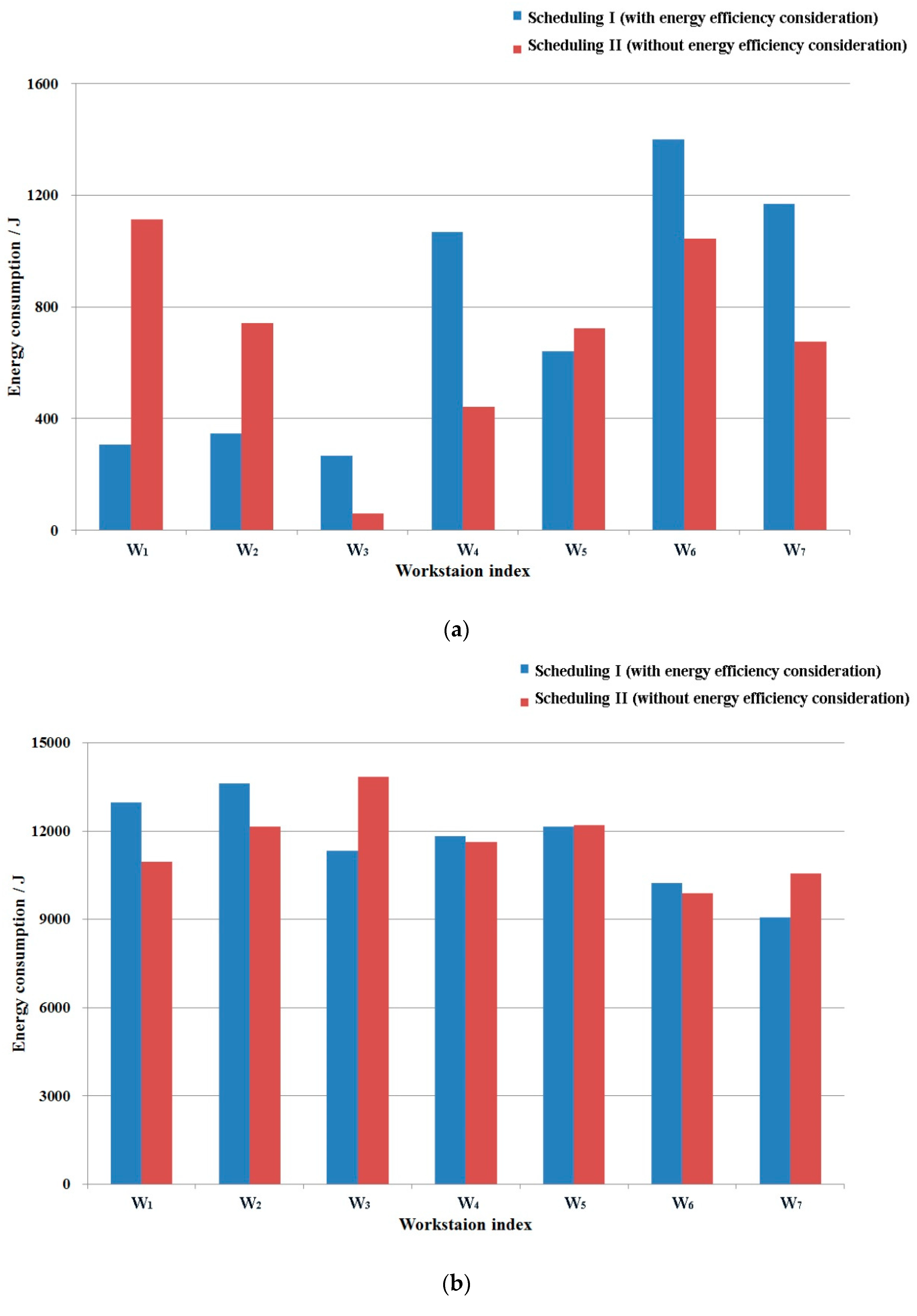
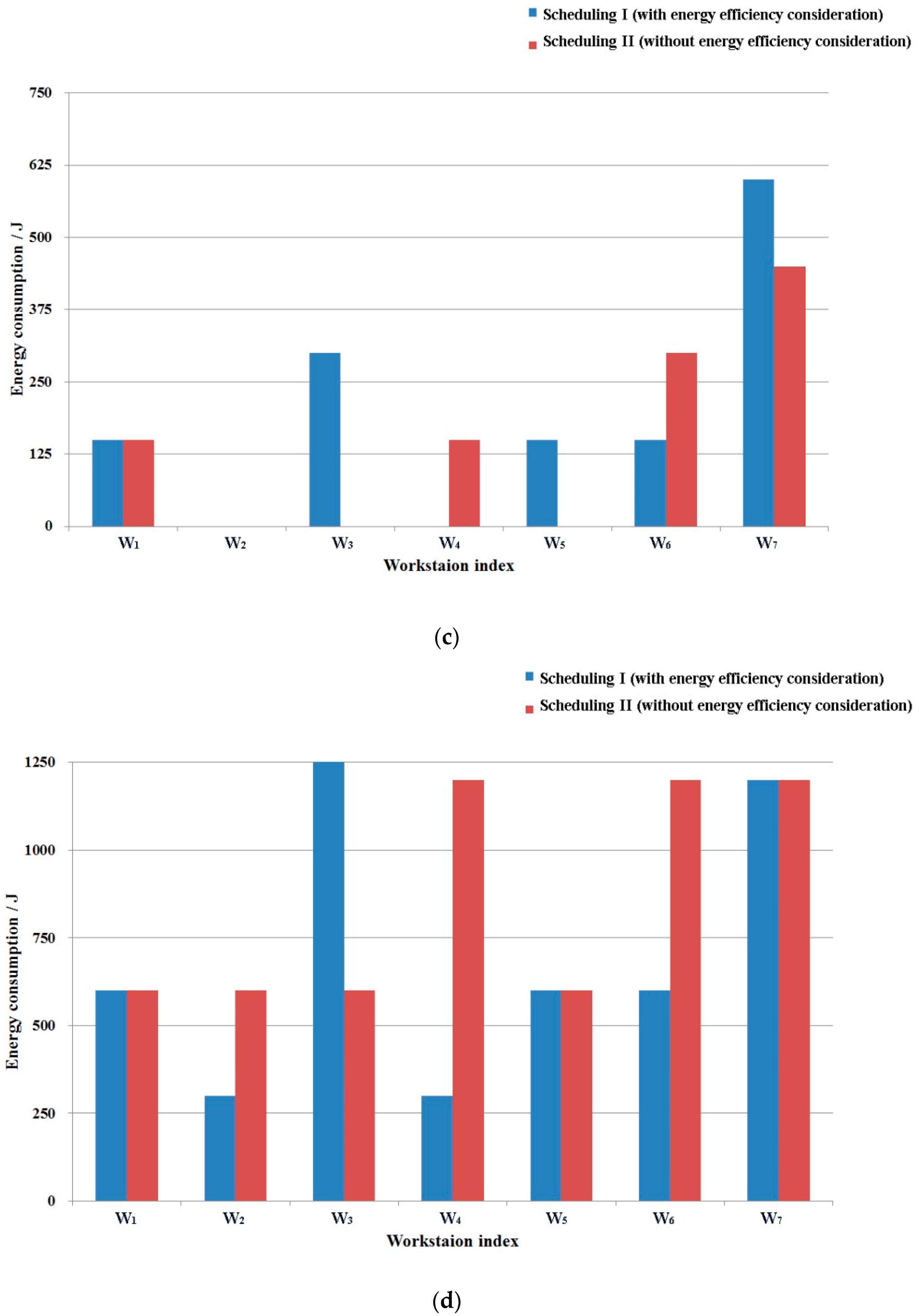
| W1 | 306.2 | 12,984.5 | 150.0 | 600.0 | 14,040.7 |
| W2 | 347.0 | 13,632.5 | 0.0 | 300.0 | 14,279.5 |
| W3 | 268.0 | 11,330.0 | 300.0 | 1500.0 | 13,398.0 |
| W4 | 1067.0 | 11,832.5 | 0.0 | 300.0 | 13,199.5 |
| W5 | 642.0 | 12,145.0 | 150.0 | 600.0 | 13,537.0 |
| W6 | 1400.0 | 10,250.0 | 150.0 | 600.0 | 12,400.0 |
| W7 | 1170.0 | 9075.0 | 600.0 | 1200.0 | 12,045.0 |
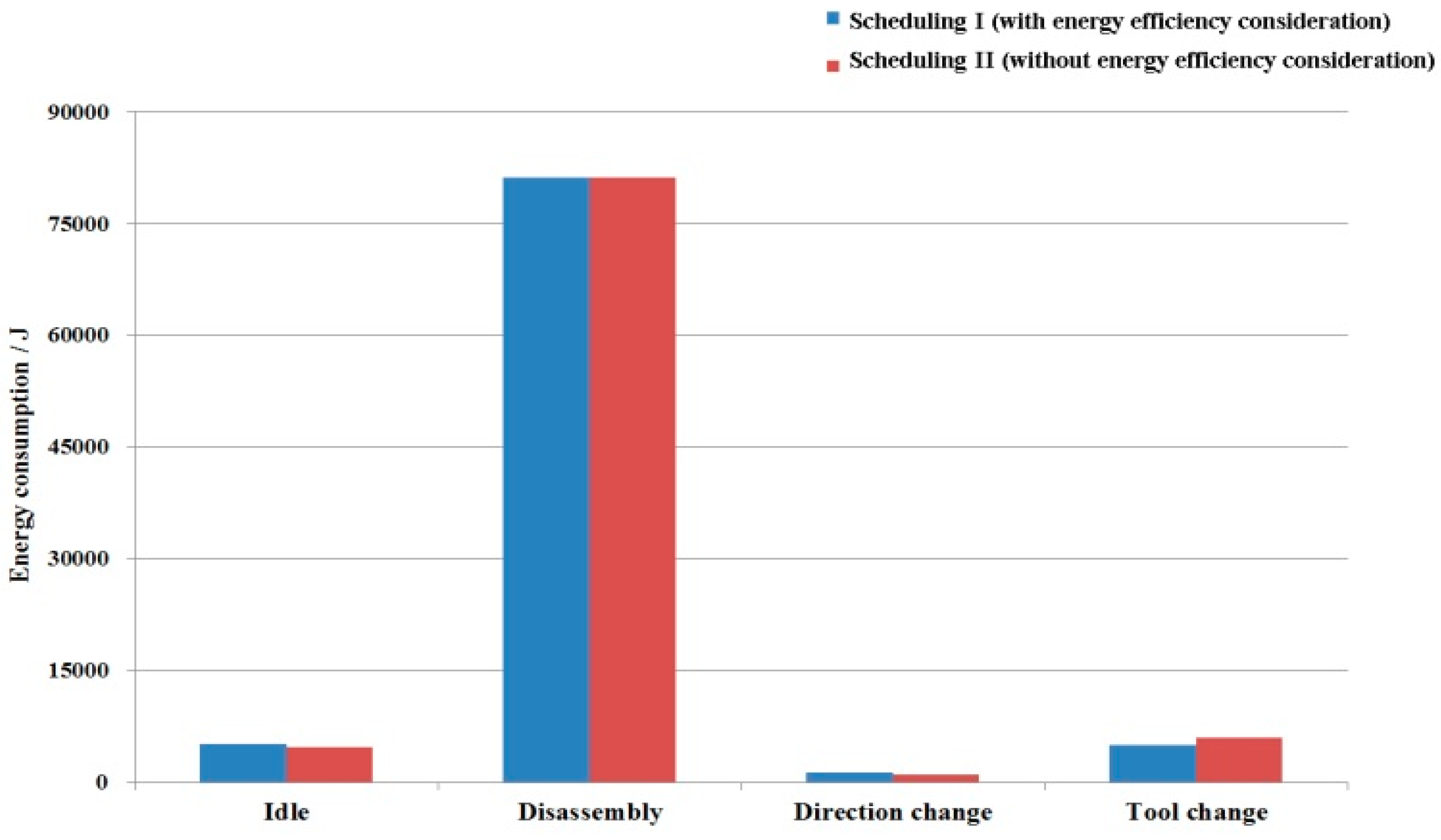
| Total | 5200.2 | 81,249.5 | 1350.0 | 5100.0 | 92,899.7 |
| Optimal Solution of DLBP | |||
|---|---|---|---|
| Scheduling I | Scheduling II | ||
| f1: Number of workstations | 7 | 7 | |
| f2: Similarity degree of working load | 0.911 | 0.923 | |
| f3: Energy consumption/J | Idle | 5200.2 | 4800 |
| Disassembly | 81,249.5 | 81,249.5 | |
| Direction change | 1350.0 | 1050.0 | |
| Tool change | 5100.0 | 6000.0 | |
| Total | 92,899.7 | 94,342.2 | |
© 2018 by the authors. Licensee MDPI, Basel, Switzerland. This article is an open access article distributed under the terms and conditions of the Creative Commons Attribution (CC BY) license (http://creativecommons.org/licenses/by/4.0/).
Share and Cite
Gao, Y.; Wang, Q.; Feng, Y.; Zheng, H.; Zheng, B.; Tan, J. An Energy-Saving Optimization Method of Dynamic Scheduling for Disassembly Line. Energies 2018, 11, 1261. https://doi.org/10.3390/en11051261
Gao Y, Wang Q, Feng Y, Zheng H, Zheng B, Tan J. An Energy-Saving Optimization Method of Dynamic Scheduling for Disassembly Line. Energies. 2018; 11(5):1261. https://doi.org/10.3390/en11051261
Chicago/Turabian StyleGao, Yicong, Qirui Wang, Yixiong Feng, Hao Zheng, Bing Zheng, and Jianrong Tan. 2018. "An Energy-Saving Optimization Method of Dynamic Scheduling for Disassembly Line" Energies 11, no. 5: 1261. https://doi.org/10.3390/en11051261
APA StyleGao, Y., Wang, Q., Feng, Y., Zheng, H., Zheng, B., & Tan, J. (2018). An Energy-Saving Optimization Method of Dynamic Scheduling for Disassembly Line. Energies, 11(5), 1261. https://doi.org/10.3390/en11051261