1. Introduction
This paper proposes a grid-supporting photovoltaic system, including implementation and performance analysis. In this section, the background, literature review, formulation of the problem of interest for this investigation, scope and contribution of this study, and organization of the paper are presented.
1.1. Background and Significance
Synchronous generators (SGs), which take responsibility for frequency regulation in electric power systems (EPS), operate as inertial voltage sources, providing the inertia to slow down frequency dynamics and moderate the power imbalance between generation and consumption in an autonomous fashion. Driven by issues such as potential exhaustion of conventional fossil fuel based energies (e.g., coal, oil, and natural gas) and increasing environmental concerns, the quantity of renewable energy sources (RES) integrated into EPS is escalating [
1,
2]. In consequence, SGs are gradually being replaced by inverters with high penetration of RES.
Among RES, solar energy via photovoltaic (PV) systems is one of the most promising, and has largely penetrated the global energy market [
3,
4]. A decrease of investment costs, technological development, and governmental support has led to the significant increase in PV systems that has been seen in recent years, and there is still significant need for growth [
1,
5].
However, grid-connected inverters are controlled as current sources with phase-locked loops (PLL) in conventional PV systems [
6], which turns conventional PV systems into power injectors and grid-following units [
7,
8]. As power injectors, conventional PV systems inject the power extracted from the PV array to EPS without the capability to mitigate the power imbalance between generation and consumption. Meanwhile, conventional PV systems, as grid-following units, provide little of the inertia that plays an essential role in short-term system stability [
9], thus the increasing penetration of PV generators reduces the inertia of EPS, which exacerbates the system’s stability [
9,
10,
11]. Therefore, implementing the function of a supporting grid in PV systems, which offers inertia and participates in frequency regulation, is significantly beneficial to the stability enhancement of EPS.
1.2. Formulation of the Problem of Interest for This Study
Existing research mainly concentrates on the realization of a virtual synchronous generator (VSG) and the improvement of the performance of inverters that are assumed to be supplied by stiff DC voltage sources. However, rare attention has been paid to the realization of a VSG in practical PV systems. It is a challenge to introduce inertia, the indispensable property for VSGs, into an inverter only powered by a PV system. To enable the inverter to emulate the inertia of SGs, an energy buffer, whose function is identical to a rotor for kinetic energy, needs to be installed at the dc link of the inverter.
The main objective of this paper is therefore to equip PV systems with the function of supporting the grid through emulating SG characteristics, then analyze the performance, formulate the stability constraint, and corroborate the implemented function with numerical experiments.
1.3. Literature Review
Virtual synchronous generator (VSG) technology, which controls inverters to mimic the characteristics of SGs to provide inertia and participate in the frequency regulation of EPS, emerged in response to issues addressed in
Section 1.2 [
12,
13,
14,
15]. The core of VSG technology is to present the various energy sources interfaced to the grid through power electronic converters as SGs [
16]. Researches on VSGs in References [
12,
13,
14,
15] are devoted to realizing the basic function of emulating inertia using converters. Recently, VSG research focus towards developing novel control strategies, and improving the performance of these strategies from the point-of-view of enhanced dynamics, stability, and so on. Compared with the method investigated in Reference [
14], the filter inductance of the synchronverter studied in Reference [
17] is virtually increased to improve the stability. In the early Ise lab’s topology presented in Reference [
15], active power oscillation becomes one of the major concerns during the emulation of inertia [
18]. In Reference [
18], an alternating moment of inertia is proposed to suppress such oscillation. Furthermore, the self-adaptive inertia and damping approach is presented to improve the dynamics in Reference [
19]. To smooth transitions and reduce frequency excursions, a particle swarm optimization technique was developed in Reference [
20], a self-tuning VSG was investigated in Reference [
21] and an auxiliary loop is proposed to adjust the dynamic response speed through correct the damping in Reference [
22].
In References [
14,
23], inverters that mimic SGs were studied with an assumption that inverters are supplied by stiff DC voltage sources, but inverters only energized by PV systems cannot satisfy this assumption. In Reference [
24], a VSG was realized by a battery/ultracapacitor hybrid ES system, but the inverters based on RES were not competent in emulating the characteristics of SGs. In References [
15,
25], it is pointed out that energy storage (ES) should be installed to emulate the kinetic energy stored in the rotating rotors of SGs, but the detailed system topology is not considered, nor is the control strategy coordinating ES and the renewable energy generator. In References [
26,
27], ES is applied to a PV system to smooth power fluctuation, and this system possesses no characteristics of SGs. In Reference [
28], a battery is used as the backup for a PV inverter that employs only PQ control or droop control, causing the inverter to operate unlike SGs.
1.4. Scope and Contribution of This Study
Motivated by the above observations, this paper presents a novel grid-supporting PV system, achieving emulation of SG characteristics. Consequently, the grid-supporting PV system, behaving as SGs, contributes to supporting the grid by autonomously mitigating the power imbalance between generation and consumption, and slowing down frequency dynamics with virtual inertia. Accordingly, the proposed grid-supporting PV system is superior to the conventional PV system, while the conventional PV system cannot moderate the deficits and surplus of power in the grid, and is unable to provide inertia.
1.5. Organization of the Paper
The content of this paper is organized as follows:
Section 2 introduces the topology and control scheme. In
Section 3, performance analysis is conducted, and the stability constraint is obtained through the established small-signal model. Results of case studies conducted on a modified CIGRE LV network benchmark are presented and discussed in
Section 4.
Section 5 draws the conclusions of this paper and discusses future research directions.
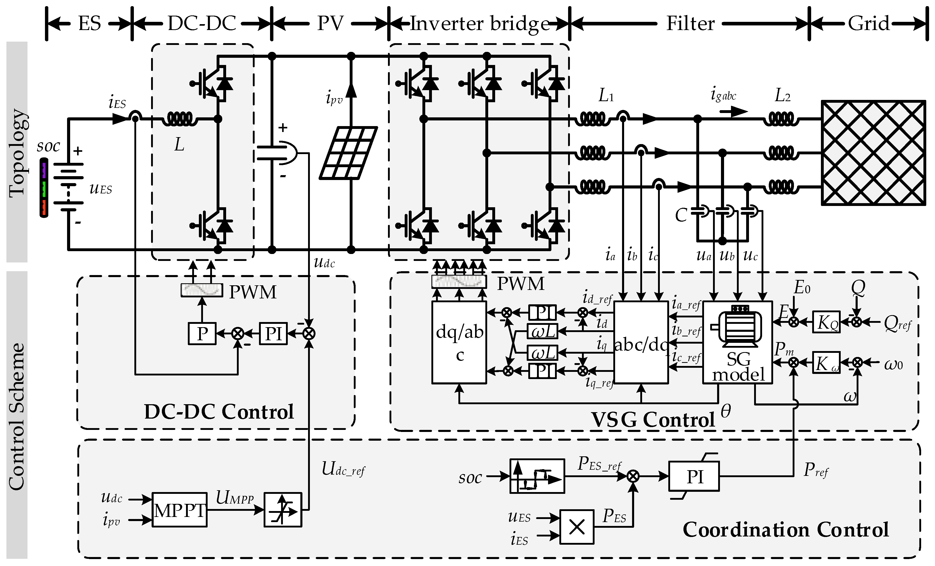
2. Topology and Control Scheme
Figure 1 shows the topology and control scheme of the grid-supporting PV system. In order to mimic the kinetic energy stored in the rotating rotors of SGs, an energy storage (ES) unit equipped with a bidirectional DC-DC converter was installed in the conventional PV system. Accordingly, the hardware consists of an ES unit, a bidirectional DC-DC converter, an inverter, and a PV array. The PV array was tied directly to the dc link, sharing the same dc bus with the DC-DC converter and the inverter. A buck/boost converter is adopted in this paper.
As
Figure 1 depicts, the overall control scheme of the grid-supporting PV system comprises three strategies: DC-DC control, VSG control, and coordination control. The coordination control is designed to attune the system with two tasks: (1) One is to ascertain the value of the dc link voltage reference
Udc_ref, utilizing a maximum power point tracking (MPPT) algorithm to draw maximum power from the PV array.
Udc_ref is provided for DC-DC control, which performs the regulation of dc link voltage
udc. (2) Another is to constrain the state of charge (SOC) of the ES unit through regulating the inverter active power reference
Pref, which capacitates the buck/boost to control
udc for the inverter emulating SGs.
Pref is delivered to the VSG control that drives the inverter to emulate the characteristics of SGs.
The conventional PV system is only energized by PV input, and its interface inverter is controlled by a voltage-oriented control method, with an outer dc link voltage control loop and an inner current control loop [
29]. As shown in
Figure 1, the proposed grid-supporting PV system however, is energized by a PV array and ES unit, and the interface inverter is driven by the VSG control. Benefiting from the topology and control scheme, which are different from those of the conventional PV system, the grid-supporting PV system is able to provide inertia and participate in frequency regulation as SGs.
2.1. Coordination Control
To behave as an energy buffer like a rotating rotor, the ES unit must have not only energy to release, but also capacity to store absorbed energy. Therefore, the SOC of the ES unit must be kept within a proper range. Meanwhile, it is necessary to constrain the SOC to control the dc link voltage udc, so that the ES unit can release energy when udc falls, and store the absorbed energy when udc rises.
To constrain the SOC, the exchanged power PES (positive for discharge and negative for charge) between the ES unit and the dc link must be regulated. However, PES cannot be directly controlled by the buck/boost converter, which is resulted from that the DC-DC control performs the regulation of udc.
According to the law of conservation of energy, the following equation is obtained when the energy change of the capacitor at the dc link is ignored:
where
Ppv is the power generated by the PV array, and
Pe is the output active power of the inverter in the system.
Since the PV array operates at the maximum power point,
Ppv in Equation (1) fails to adjust. Thus, regulating
Pe is the only way to control
PES. Due to the emulated SG characteristics of the inverter,
Pe can be controlled with coordination control through regulating the inverter active power reference
Pref. To track the exchanged power reference
PES_ref, a proportional-integral (PI) regulator, whose input is the error between
PES_ref and
PES, is used for generating
Pref. Then,
Pref can be expressed as
where
GPI(
s) =
Kp +
Ki/
s is the transfer function of the PI regulator,
Kp and
Ki are the proportional coefficient and integral coefficient of the PI regulator, respectively, and
s is the Laplace operator.
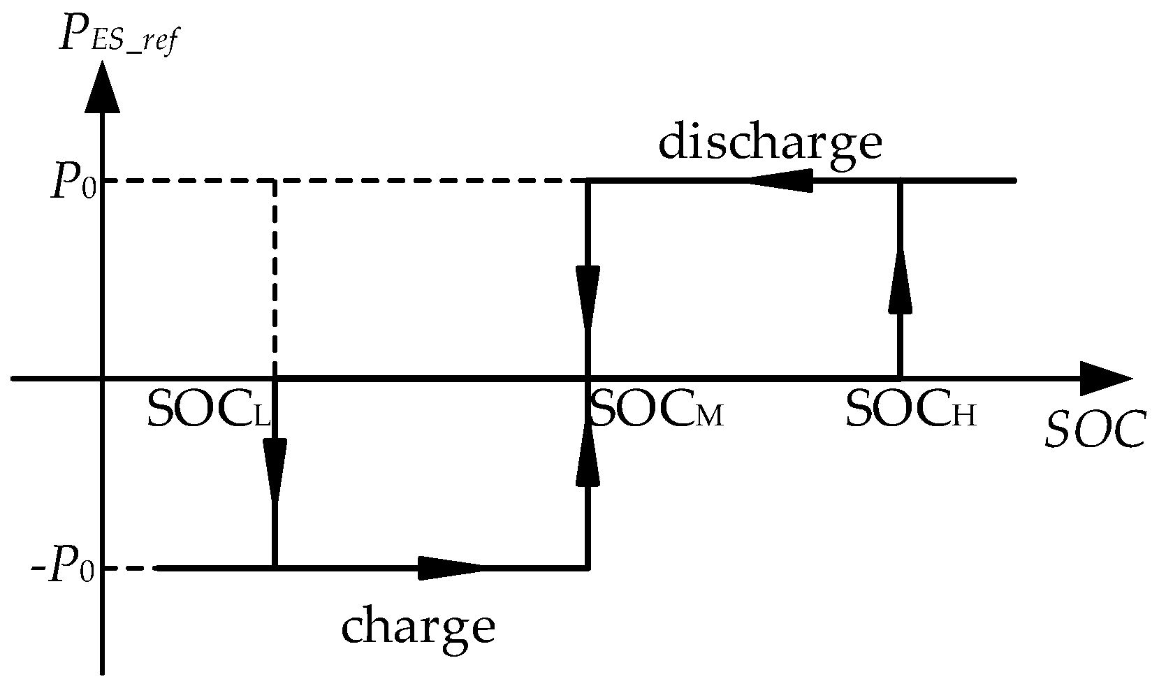
The relationship of exchanged power reference
PES_ref with respect to the SOC is designed as shown in
Figure 2, where SOC
M is the mean of lower limit SOC
L and higher limit SOC
H, and
P0 is the absolute value of the charge power and the discharge power. The ES unit starts charging once the SOC is less than SOC
L, and discharging when the SOC is more than SOC
H. Both charging and discharging are terminated when the SOC reaches SOC
M. Applying the curve shown in
Figure 2 to specify
PES_ref, frequent operations of charge/discharge near SOC
L/SOC
H can be avoided by the coordination control. As the charge power and the discharge power of the ES unit depend on
P0, the rated power of the inverter and the charge-discharge rate (C-rate) of the ES unit need to be taken into account when determining
P0. First, the charge power and the discharge power of the ES unit should not be more than the rated power of the inverter to protect the inverter from over-current. Second,
P0 should ensure the charge current and the discharge current do not exceed the maximum C-rate so that the cycling life and the capacity of the ES unit are not significantly affected.
The dc link voltage reference
Udc_ref is generally equal to
UMPP, which is calculated by a maximum power point tracking (MPPT) algorithm, to ensure that the PV array operates at the point where it can output maximum power. Incremental Conductance [
30,
31], a classical MPPT algorithm, is employed in this paper.
2.2. VSG Control
The VSG control aims to equip the inverter with the characteristics of a SG so that the inverter is capable of behaving like the SG. To realize the inverter emulating the characteristics of the SG, there are three sub-processes to implement during one carrier cycle, as illustrated in
Figure 1. The voltages of the filter capacitors,
ua,
ub and
uc, are measured in real time, and virtualize the phase terminal voltages of the stator windings and serve as the input variables of a SG model. Through solving the model, the stator currents of the SG,
ia_ref,
ib_ref, and
ic_ref, are obtained as the reference currents for the inverter. To complete the emulation of the SG characteristics, the inverter output currents should be driven to track the reference currents. Thus, proportional-integral (PI) regulators in the rotating frame are employed to control the inverter.
The SG model adopted in this work comprises third-order electrical equations and second-order mechanical equations. The electrical equation set, which reproduces the stator circuit of the SG, is given by
where
uabc = [
ua,
ub,
uc]
T denotes the phase terminal voltages of the stator windings;
Rs and
Ls are respectively the stator resistance and the stator inductance;
iabc_ref = [
ia_ref,
ib_ref,
ic_ref]
T represents the currents of the stator windings, which serve as reference currents for the inverter; and
eabc = [
ea,
eb,
ec]
T =
E[sin
θ, sin(
θ − 2
π/3), sin(
θ + 2
π/3)]
T denotes the induced phase electromotive forces in the stator windings.
The electromechanical characteristics of the SG, neglecting the mechanical losses and considering the effect of damper windings, can be described as
where
H is the inertia constant,
Pm is the mechanical power,
D is the damping coefficient,
ω and
ω0 are the actual and the nominal angular frequency, respectively, and
θ is the electrical rotation angle.
To emulate the droop characteristics of the primary frequency control (PFC) and primary voltage control (PVC),
Pm and
E can be expressed as
where
Kω is the unit power regulation,
E0 is the no-load electromotive force (EMF),
Qref and
Q are the reference value and the actual value of the inverter output reactive power, respectively, and
KQ is the voltage droop coefficient.
2.3. DC-DC Control
The objective of the DC-DC control is to keep the actual value of the dc link voltage
udc equal to the voltage reference
Udc_ref provided by the MPPT algorithm of the coordination control. Regulating
udc to track
udc_ref enables the PV array to operate at the maximum power point. The DC-DC control strategy incorporates an outer voltage loop with an inner current loop, as depicted in
Figure 1. Through DC-DC control, a stiff dc link voltage, which is required to emulate the inertia, is provided for the inverter.
The buck/boost converter works in BUCK mode and charges the ES unit to prevent udc from rising when Ppv > Pe. Under the condition of Ppv < Pe, the buck/boost converter operates in BOOST mode and discharges the ES unit to stop udc from dropping. This indicates that the ES unit behaves as an energy buffer, emulating a rotating rotor through complementing the deficit, or absorbing the surplus, of PV production.
3. Performance Analysis and Stability Constraint Formulation
In this section, a small signal per unit (pu) model that considers the Q-E droop control is established. Utilizing the model, performance analysis is conducted, the impact of the Q-E droop control on stability is investigated, and the stability constraint is obtained.
3.1. Small-Signal Modelling
Figure 3 depicts the equivalent circuit of the inverter when connected to the grid. In this figure,
δ is the power angle;
Ug is the amplitude of the grid voltage;
Rs +
jXs is the virtual stator impedance implemented by the VSG control;
Rg +
jXg is the grid impedance, which includes the line impedance; and the grid-side filter impedance
jωL2 and
Pe +
jQ is the apparent power measured for the control scheme.
When
Rs and
Rg are neglected due to
Xs ⪢
Rs and
Xg ⪢
Rg,
Pe and
Q can be expressed according to
Figure 3 as follows:
Linearizing
Pe and
Q with respect to
E and
δ, the deviations of
Pe and
Q are given by
where Δ
x (
x =
Pe,
Q,
E, and
δ) represents the deviation of
x, and
The small signal model of the
Q-
E droop control described by Equation (7) is given by
Solving Equations (10), (11), and (16), Δ
Pe and Δ
Q can be further derived as
Normalizing and linearizing Equations (4) and (5) yields [
32]
where Δ
ω is the angular frequency deviation, Δ
Pm is the deviation of
Pm,
D is the damping coefficient,
H is the inertia constant in seconds, and
ω0 is the nominal angular frequency in rad/s.
The incremental Equations of (1), (2) and (6) are
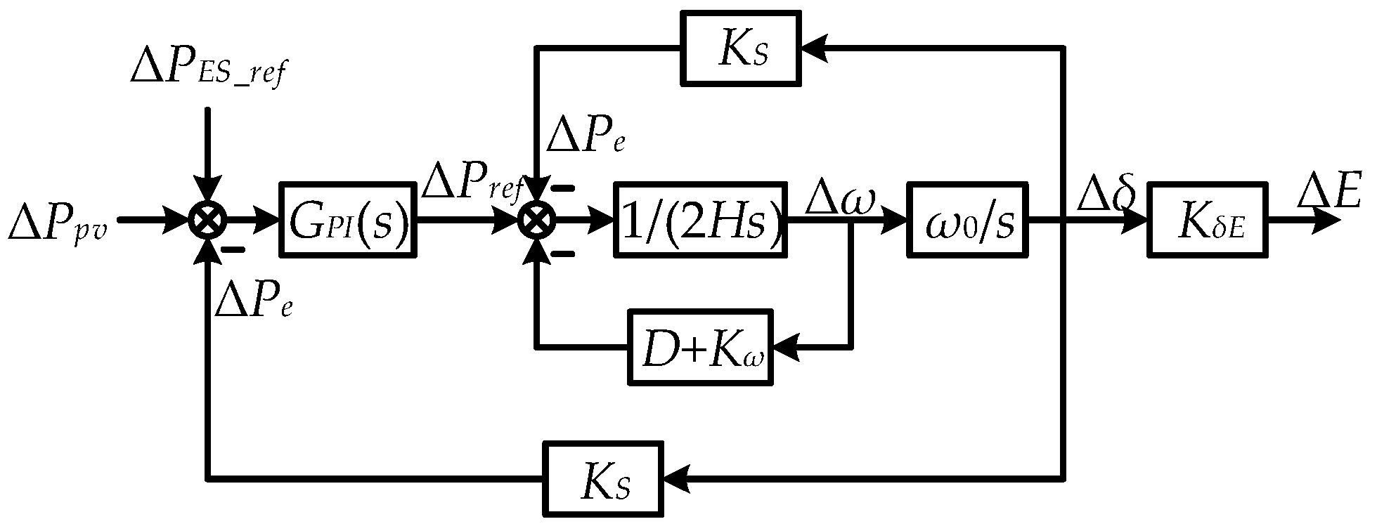
By combining Equations (17)–(24), the small-signal model considering the
Q-
E droop control is established in
Figure 4, and Δ
ω is correspondingly derived as Equation (25).
where the transfer function
G(
s) is given by
The expected performance of the grid-supporting PV system can be achieved if H, D + Kω, Kp, and Ki are properly selected in such a way that the poles of Equation (26) are located at desired locations.
3.2. Performance Analysis
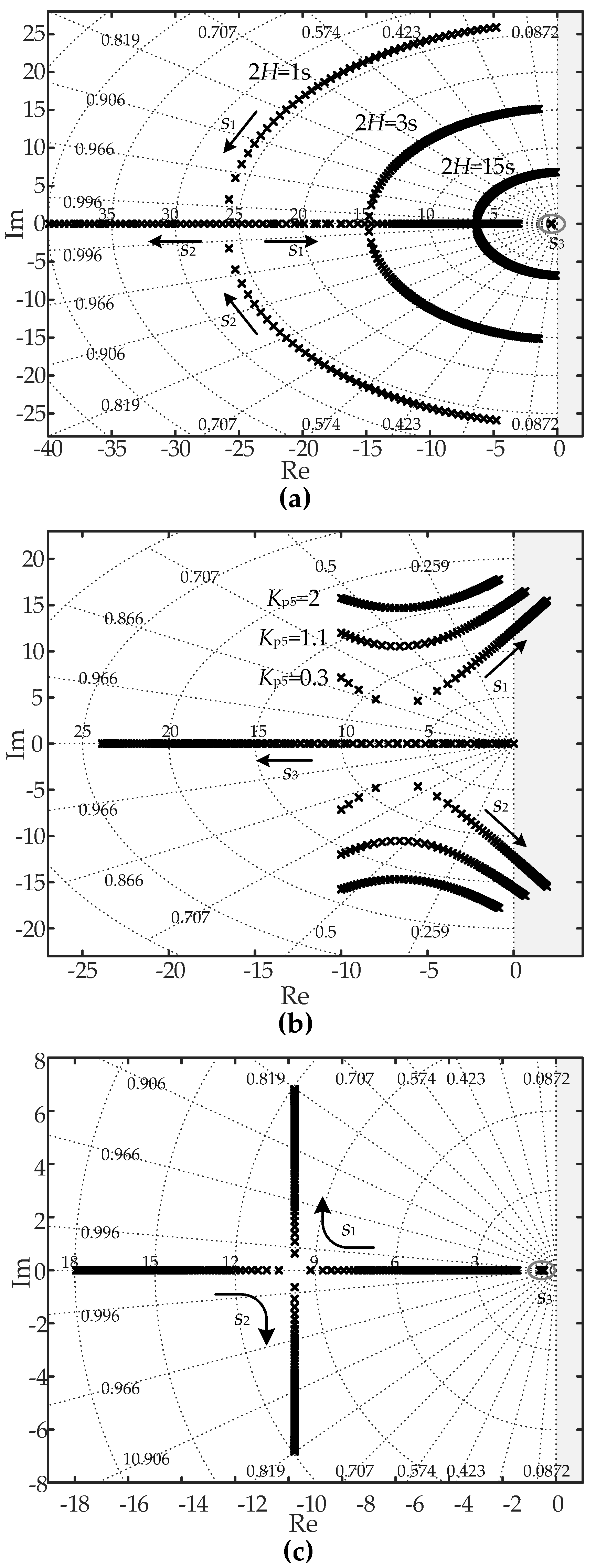
The root loci family of the proposed PV system is shown in
Figure 5a, where 2
H = 1 s, 3 s, and 15 s, and
D +
Kω changes from 10 pu to 200 pu. It is clear that
H plays an important role in determining the settling time of the proposed PV system. As
D +
Kω increases, the damping of the system rises and the stability is improved.
Figure 5b depicts the root loci family considering variations of
Ki from 0.1 pu to 50 pu, and
Kp = 0.3 pu, 1.1 pu, and 2 pu. As
Figure 5b shows, the damping drops, the overshoot rises, and the undamped natural frequency increases when
Kp becomes larger. The damped frequency and the stability margin mainly depend on
Ki. Instability may happen with an excessively large value of
Ki. To ensure the stability of the system, it is necessary to formulate the constraint explicitly on
H,
D +
Kω,
Kp, and
Ki to guide the tuning of parameters.
Figure 5c depicts the root locus where
KS varies from 0.5 pu to 2 pu. Among the three poles depicted in the plane,
s3 is the real root and its position depends on
Kp and
Ki. As
KS increases, the conjugate complex roots
s1 and
s2 evolve in the direction of the arrows. A larger
KS increases the real parts of
s1 and
s2, which improves the stability.
3.3. Impact of Q-E Droop Control on Stability
As
Figure 5c illustrates,
KS is a factor that affects the stability of the grid-supporting PV system. According to Equation (17),
Ks consists of two parts,
kPδ and Δ
KS. It is indicated in Equation (19) that Δ
KS is related to the coefficient
KQ of the
Q-
E droop control and embodies the impact of the
Q-
E droop control on the stability. When the
Q-
E droop control is invalidated (i.e.,
KQ = 0) and only
P-
ω is considered, Δ
KS vanishes identically, and
KS in Equation (17) is equal to
kPδ.
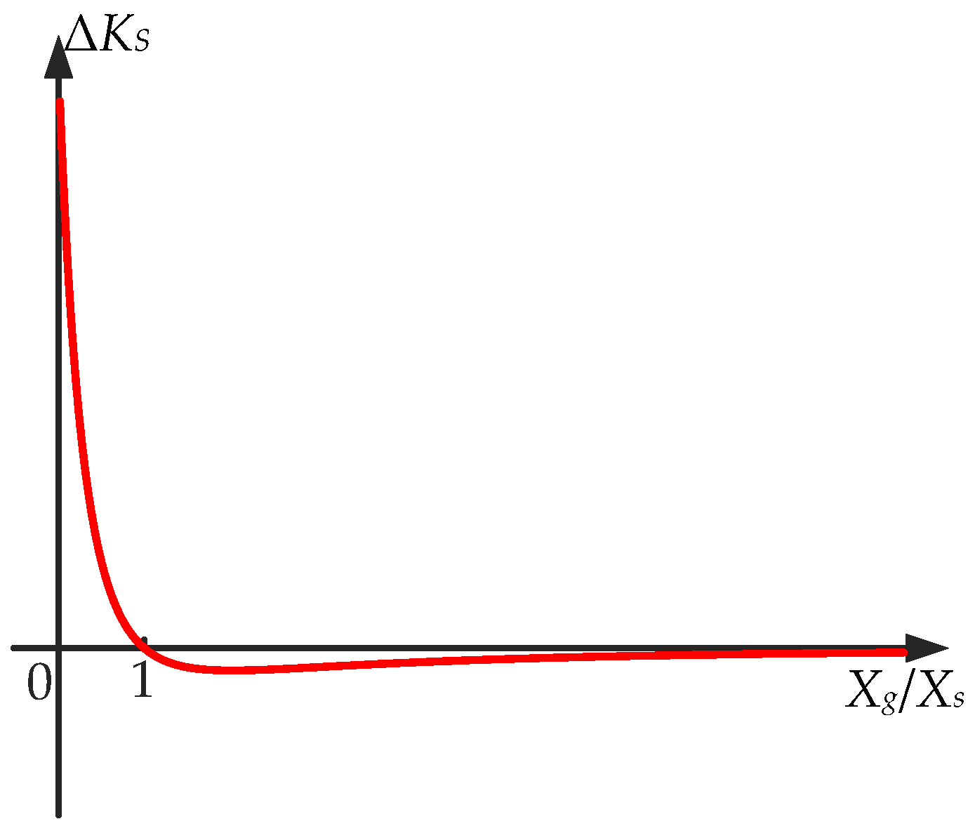
By substituting Equations (13)–(15) into Equation (19), Δ
KS can be obtained as Equation (27), where
r =
Xg/
XS. On the condition that the
Q-
E droop control works,
KQ is set to be a positive number. The power angle
δ lies in the range from 0° to 90°, and
E is generally larger than
Ug. Thus,
kPδ,
kPE, and
kQE are all positive. Accordingly, the curve of Δ
KS with respect to the ratio
Xg/
XS is shown in
Figure 6.
As
Figure 6 illustrates, Δ
KS is positive if the ratio
Xg/
XS is less than 1, while Δ
KS is negative if the ratio
Xg/
XS is greater than 1. Accordingly,
KS is greater than
kPδ under the condition of
Xg <
XS, which means the
Q-
E droop control improves the stability, since a larger
KS improves the stability. Conversely,
KS is less than
kPδ when
Xg >
XS, which indicates that the
Q-
E droop control worsens the stability in the weak grid. Besides,
KS is zero in the case of
Xg =
XS, implying that the
Q-
E droop control has no effect on the stability.
3.4. Stability Constraint Formulation
The closed-loop system of Equation (26) is a third-order linear time-invariant. To analyze the stability, the Routh–Hurwitz stability criterion is used. The system characteristic equation is obtained from Equation (26) as
where
a0 = 2
H,
a1 =
D +
Kω,
a2 =
ω0KS(
Kp + 1), and
a3 =
ω0KSKi.
Through applying the Routh–Hurwitz stability criterion to Equation (28), the system stability discriminant is yielded as
Since
H,
D +
Kω,
Kp, and
Ki are positive real numbers, the discriminant can be simplified as
Substituting
ai into Equation (30) gives
Equation (31) presents the stability constraint for the grid-supporting PV system, which H, D + Kω, Kp, Ki, and KS must satisfy to guarantee the stability of the system.
4. Results and Discussion
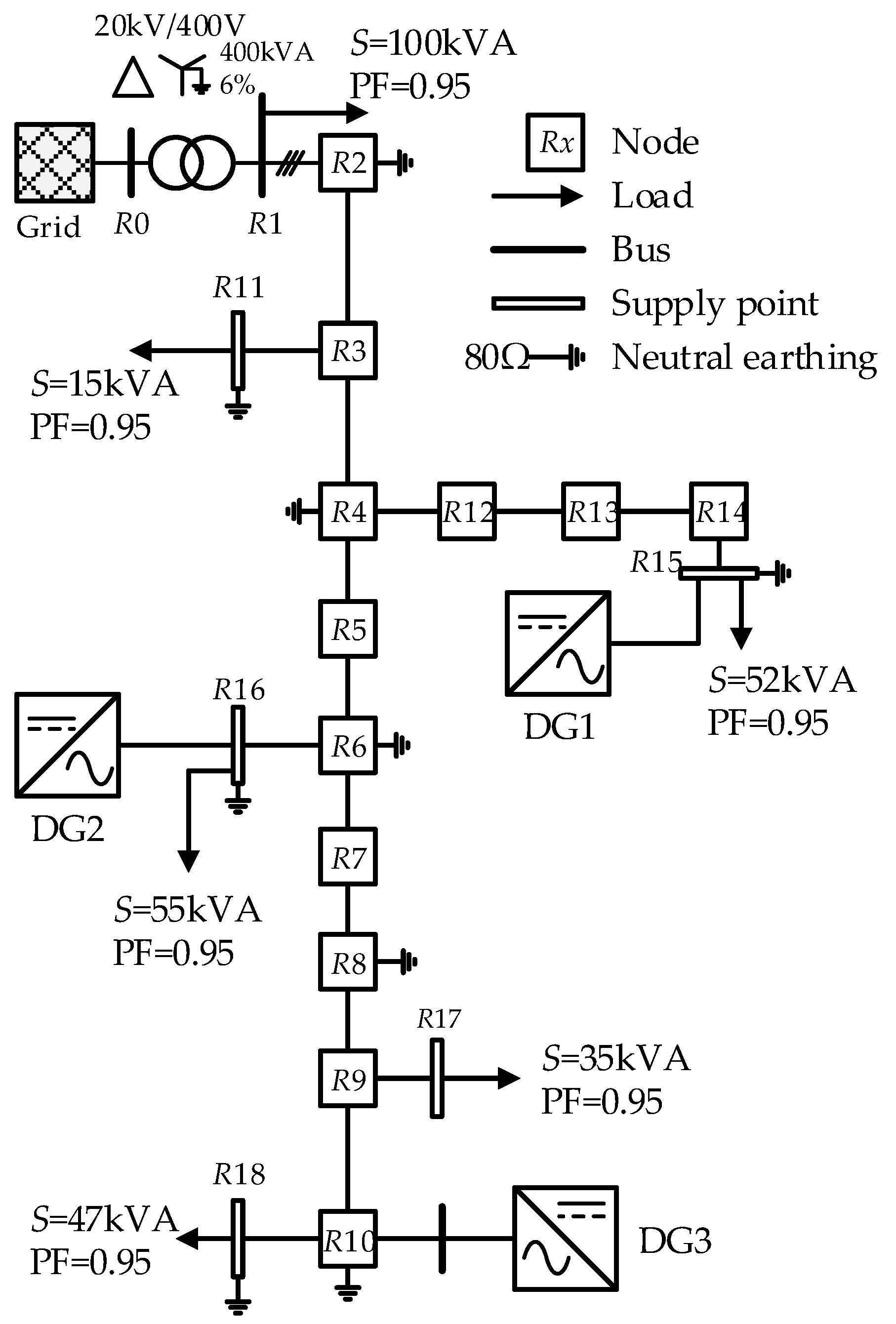
The proposed grid-supporting PV system was verified on the CIGRE benchmark of the European LV distribution network elaborated in Reference [
33]. The topology of the benchmark is shown in
Figure 7, and the line parameters of the benchmark are given in
Table 1. All loads were configured to be balanced for simplicity. The apparent power and power factor (PF) of the loads are described in
Figure 7. The 20 kV medium voltage grid in this benchmark was equated with a SG system with inertia constant of
H = 9 s [
32]. The PFC of the SG system reacts in 5 s when there is a frequency deviation, and the speed regulation of the PFC is 3.33%. Six cases were considered when disturbances occur, as listed in
Table 2.
Case A and Case B considered sudden load variation by switching a load of 25 kW in R11 at 2 s. Case C and Case D considered a three-phase short circuit fault occurring at 2 s, the fault in each case was located at R17 and was cleared at 3 s. A step of solar irradiance from 1000 W/m2 to 1050 W/m2 was exerted on the PV array of DG3 at 2 s in Case E and Case F. After the disturbance occurred at 2 s in each case, the PFC was activated in 5 s; that is, at 7 s.
In Case A, Case C, and Case E, three conventional single-stage PV systems were applied to the benchmark as DG1−DG3. In comparison with the conventional PV system, three proposed grid-supporting PV systems, with parameters listed in
Table 3, were connected to the feeder as DG1−DG3 in Case B, Case D, and Case F, and each ES unit was comprised of 25 Powersonic PS-121100 batteries in series. The SOC of each ES unit was set to 50%, which leads to
PES_ref = 0.
To verify the functions of smoothing the power and tracking the maximum power point of the conventional PV system and the proposed grid-supporting PV system, solar irradiance steps were used in Case E and Case F to provide the most severe condition, although there is little possibility that the solar irradiance step would occur in a real case.
4.1. Case A: Sudden Load Variation—Conventional PV System
Figure 8a gives the resultant frequency of the grid, DG1, DG2, and DG3, respectively. All frequencies decrease consistently between 2 s and 5 s. With the phase-lock loop, the conventional PV system tracks the grid frequency (i.e., the LV distribution network frequency), but fails to provide the inertia due to operating as a grid-following unit. As depicted in
Figure 8b, the output power of the conventional PV system injects power into the LV distribution network without change after the load variation, and thus is incapable of mitigating the power imbalance between generation and consumption.
Figure 8c illustrates the dc link voltages, which are always regulated by the inverter of the conventional PV systems to perform MPPT.
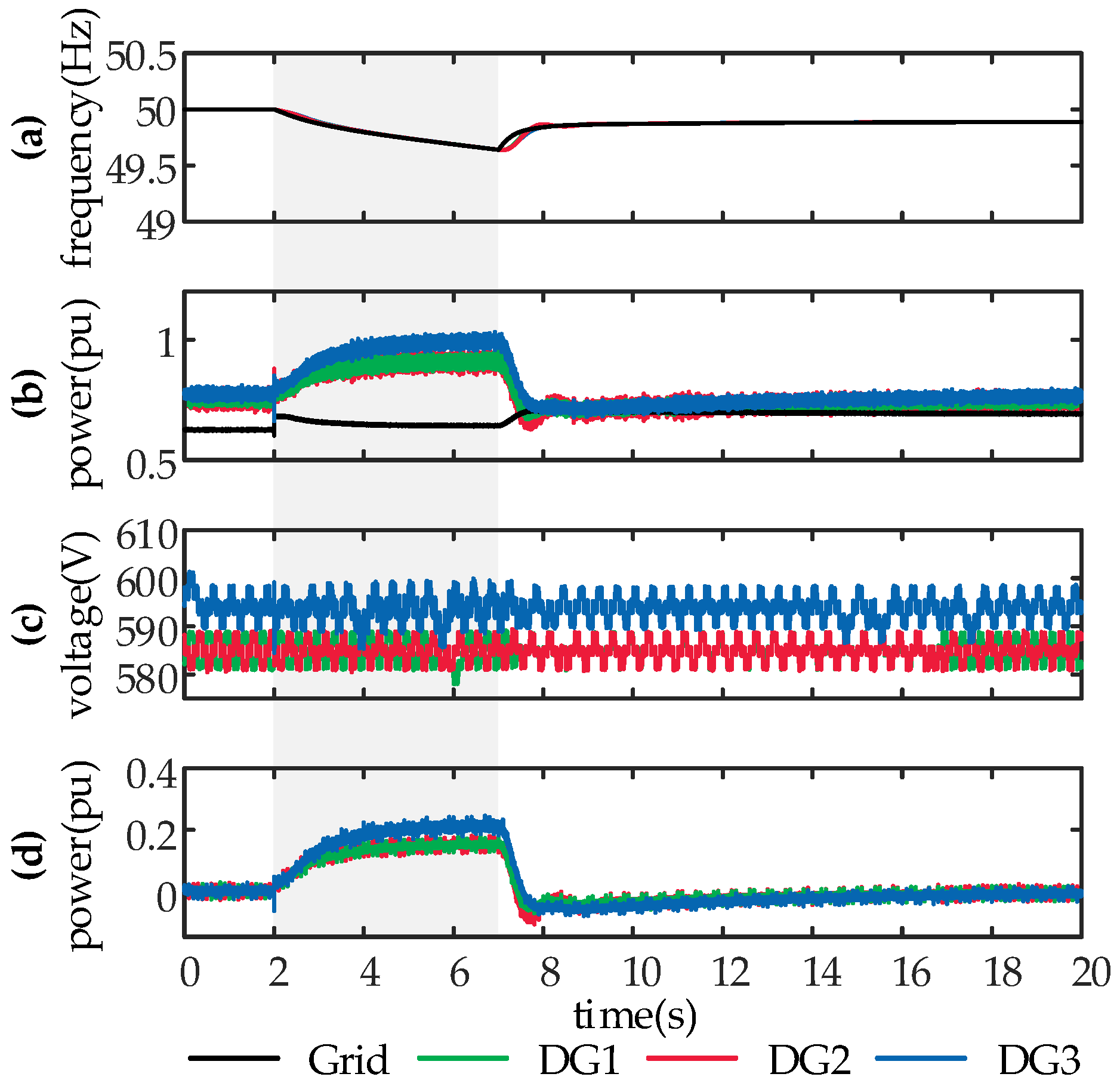
4.2. Case B: Sudden Load Variation—Proposed PV System
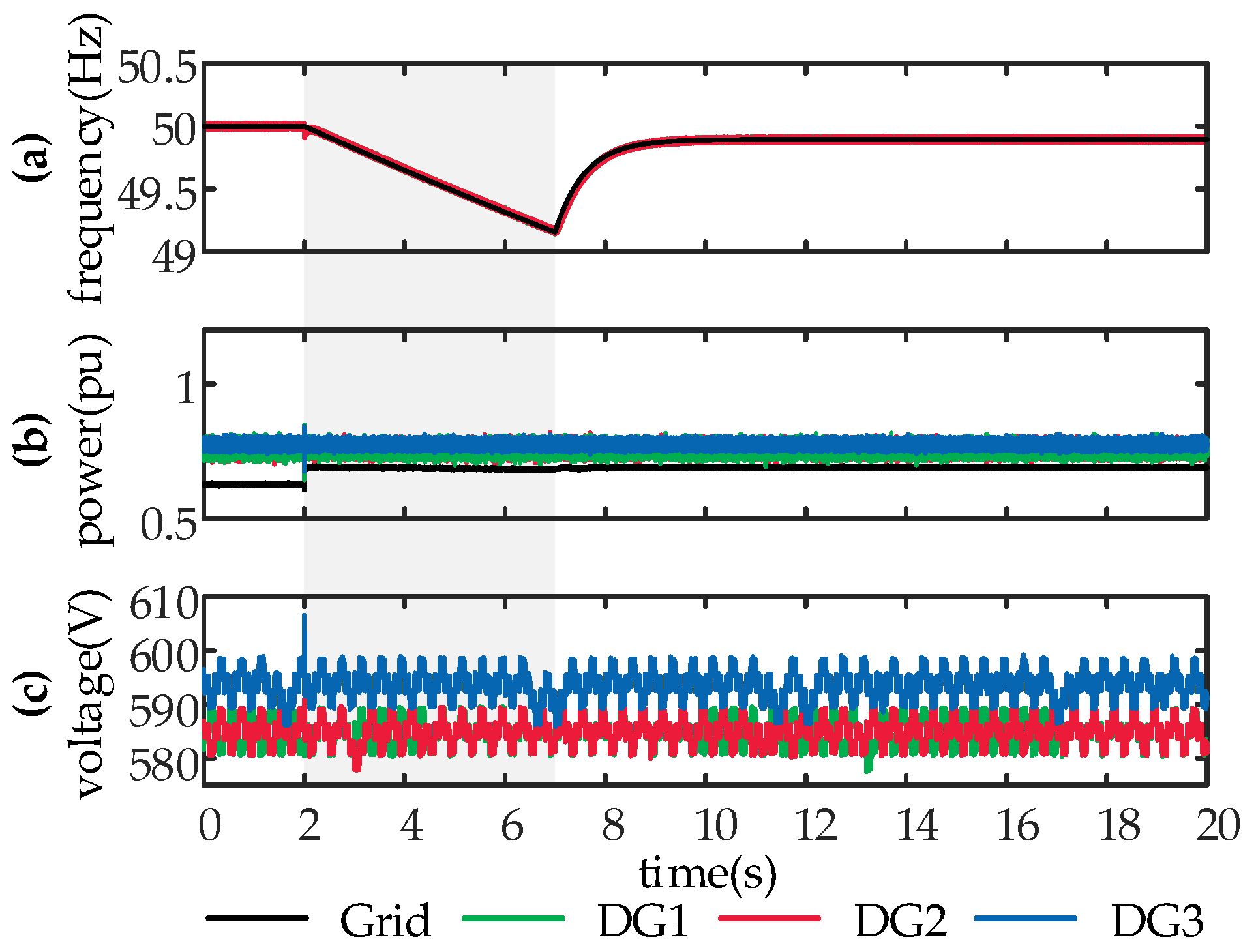
Figure 9 presents the responses when three proposed PV systems are integrated into the LV distribution network as DG1−DG3. As depicted in
Figure 9a, all frequencies decrease between 2 s and 5 s, with a smaller rate of change of frequency (ROCOF) and higher frequency nadir when compared with
Figure 8a of Case A. Through emulating the inertia of SGs, the proposed PV system is able to slow down frequency response and allow decent time for frequency control.
Figure 9b shows that the proposed PV system mitigates the power imbalance between generation and consumption by increasing the output active power
Pe autonomously, and thus supports the grid, mimicking the SG.
Figure 9c plots the dc link voltage of the interface inverter, which is maintained at
UMPP by the buck/boost converter with the ES unit, even if there is an imbalance between
Ppv and
Pe. It is demonstrated that a stiff dc link voltage can be provided in the proposed PV system for the inverter to emulate the inertia.
Figure 9d illustrates the exchanged power
PES between the ES unit and the dc link. After the sudden load variation, the incremental of
PES is consistent with that of
Pe shown in
Figure 9b. It is indicated that the ES unit balances the power between the PV array and the inverter, which emulates the behavior of a rotating rotor releasing kinetic energy when it’s frequency drops. After PFC activation, the exchanged power
PES, regulated by coordination control, gradually converges to
PES_ref to constrain the SOC.
4.3. Case C: Short Circuit Fault—Conventional PV System
As
Figure 10a depicts, the grid frequency, which is tracked by the conventional PV system, decreases until the fault is cleared and reaches the nadir of 49.82 Hz at 3 s. However, after the clearance of the fault, frequencies of the grid, DG1, DG2, and DG3 hardly change until the PFC is activated at 5 s. This shows that the conventional PV system fails to participate in frequency regulation. As
Figure 10b depicts, the power imbalance resulting from the fault is counteracted only by the grid, while the conventional PV system is incapable of responding to the power imbalance, and outputs power without change after the fault occurs. The dc link voltage, illustrated in
Figure 10c, is regulated during the fault to draw maximum power from the PV array.
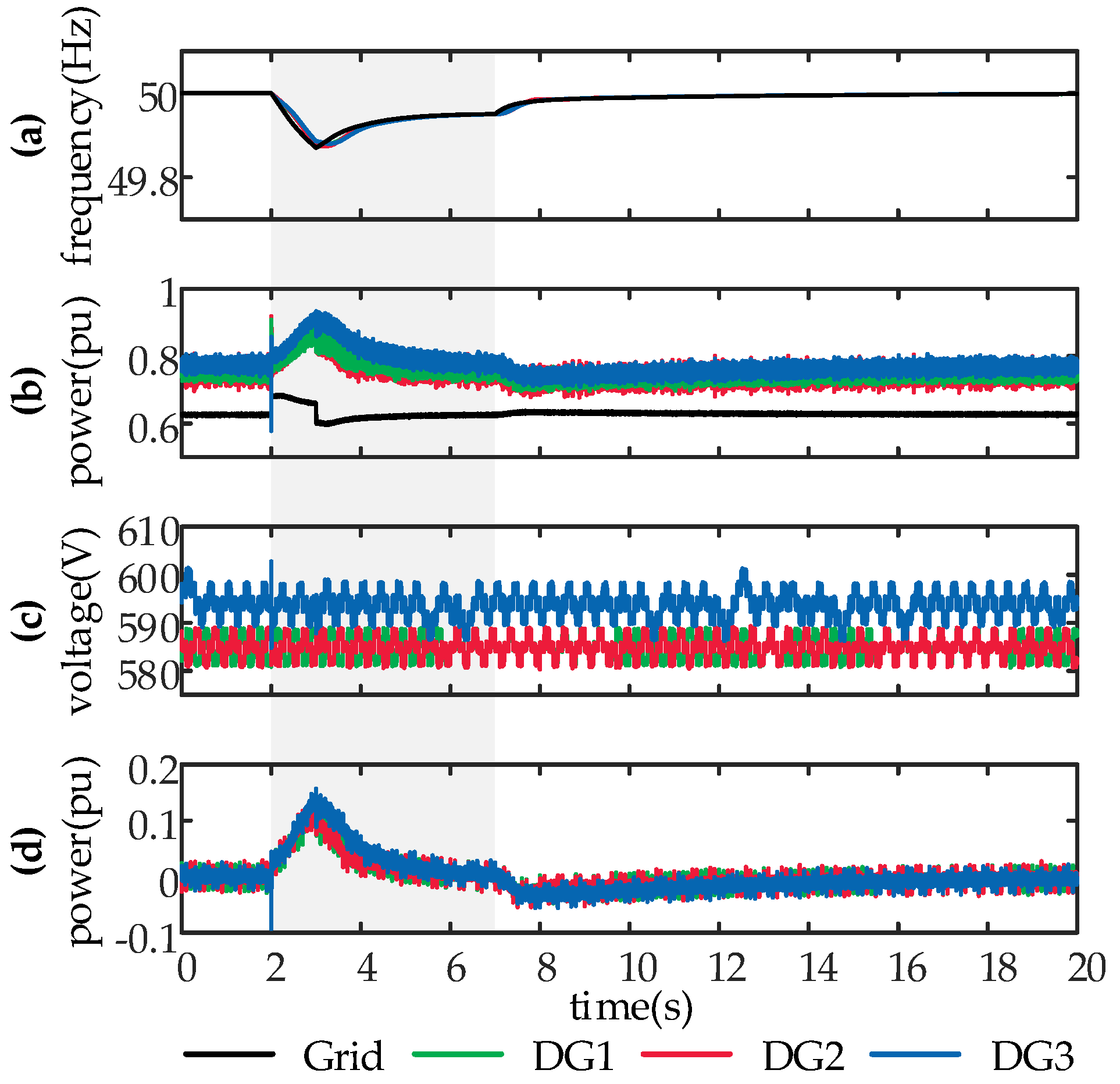
4.4. Case D: Short Circuit Fault—Proposed PV System
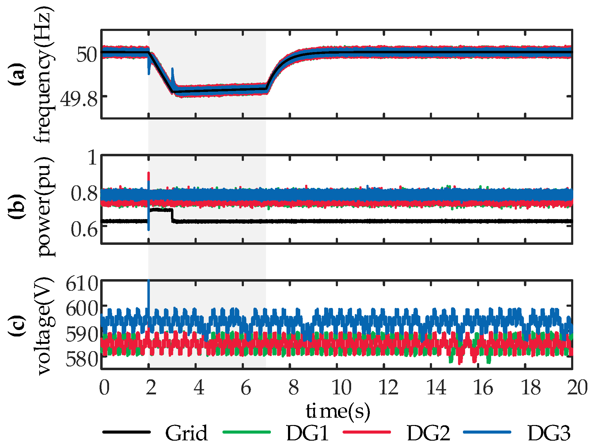
System responses to a three-phase short circuit fault, where three proposed PV systems are integrated as DG1−DG3, are studied in this case, and given in
Figure 11.
The grid frequency, as shown in
Figure 11a, decreases from the normal value of 50 Hz to the nadir of 49.87 Hz lasting from 2 s to 3 s. In comparison with Case C, a smaller ROCOF and slighter frequency deviation are caused by the fault in this case. It is perceived in
Figure 11a that the grid frequency is regulated by the proposed PV system in the absence of PFC action during 3–7 s. As depicted in
Figure 11b, the proposed PV system increases its output active power and moderates the power imbalance, while the conventional PV system fails to implement this function, as shown in
Figure 10b.
Figure 11c illustrates the dc link voltage of the proposed PV system, which indicates that the proposed PV system is able to provide a stiff dc link voltage to emulate the inertia and perform MPPT. As depicted in
Figure 11d, the incremental of
PES is consistent with that of
Pe shown in
Figure 11b, verifying that the ES unit balances the power between the PV array and the inverter, which emulates the behavior of a rotor releasing kinetic energy when it’s frequency declines.
4.5. Case E: Step of Solar Irradiance—Conventional PV System
As
Figure 12a shows, the step of solar irradiance exerted on the PV array of DG 3 causes a sudden change of the power generated from the PV array in DG3. The dc link voltage of the inverter in DG 3 increases, as depicted in
Figure 12b, to track
UMPP specified by the MPPT algorithm in the coordination control. Due to the lack of an energy buffer in the conventional PV system, DG3 injects the fluctuant PV power resulting from the solar irradiance step into the LV distribution network, and the output active power rises suddenly, as shown in
Figure 12c.
Figure 12d shows that the grid frequency deviates after the solar irradiance step until the PFC is activated.
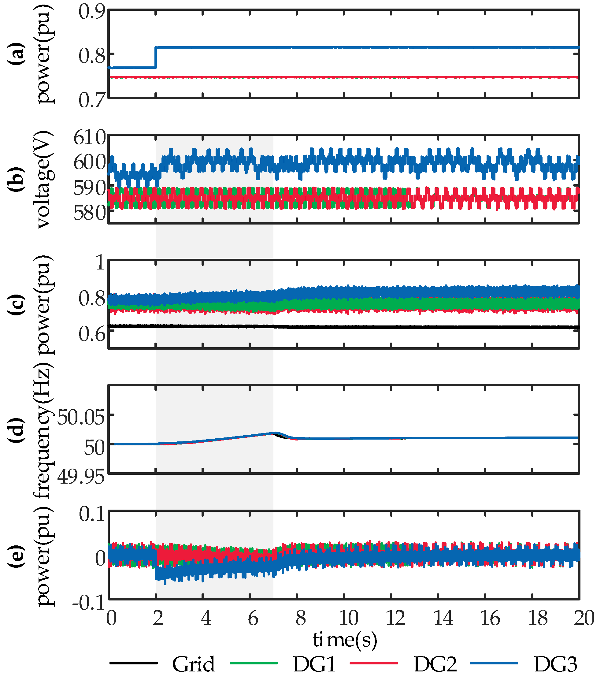
4.6. Case F: Step of Solar Irradiance—Proposed PV System
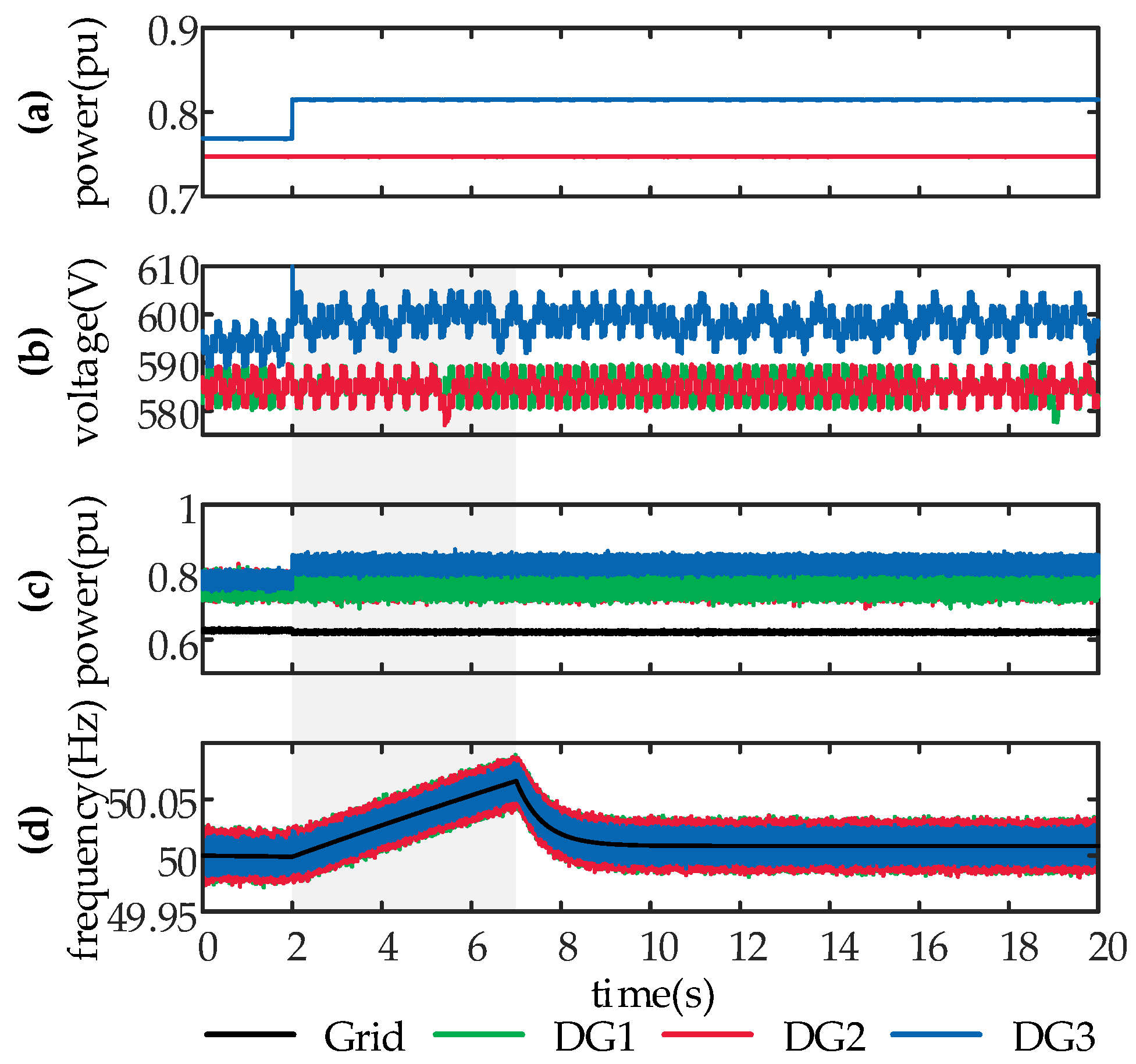
Responses to the step of solar irradiance exerted on DG3 are studied in
Figure 13 when three proposed PV systems are applied as DG1−DG3. After the solar irradiance steps, the power generated from the PV array in DG3 rises suddenly, as shown in
Figure 13a, and the dc link voltage of DG3 increases to perform MPPT, as shown in
Figure 13b. In comparison with
Case E, the active power that DG3 feeds to the LV distribution network is filtered and rises smoothly, as depicted in
Figure 13c, and the grid frequency deviates with a smaller ROCOF and lower zenith, as depicted in
Figure 13d.
Figure 13e shows that the exchanged power
PES between the ES unit and the dc link decreases suddenly, and the ES unit of DG3 absorbs the surplus of PV production after the solar irradiance steps.
PES eventually returns to zero, tracking the reference
PES_ref to constrain the SOC, and the output active power
Pe is finally equal to the power generated by the PV array
Ppv.
It is demonstrated that the proposed PV system is able to smooth the power fed to the LV distribution network, even if the power generated by the PV array fluctuates suddenly.
Combining with the results in Cases A–F,
Table 4 shows the following advantageous features of the proposed grid-supporting PV system as compared with the conventional PV system:
- (1)
The grid-supporting PV system, presenting as SGs from the point-of-view of the grid by mimicking SG characteristics with VSG control, can support the grid through mitigating the power imbalance between generation and consumption, and slowing down frequency dynamics with virtual inertia.
- (2)
Through emulating the droop characteristics of PFC and PVC, the grid-supporting PV system can participate in frequency regulation and voltage regulation.
- (3)
The proposed PV system has the functions of filtering the PV power and smoothing the power fed to the grid, which leads to a reduced impact of PV fluctuation on the grid.
- (4)
The grid-supporting PV system synchronizes with the grid through mimicking the synchronization mechanism of SGs, and thus the PLL, in which the delay may cause instability [
34], is discarded in the proposed PV system.
5. Conclusions
A novel grid-supporting PV system, which operates as an inertia voltage source by emulating the characteristics of SGs, is proposed in this paper.
To present the PV system as a SG from the point-of-view of the grid, both the topology and the control scheme were investigated. An ES unit equipped with a bidirectional DC-DC converter was installed, which can mimic the function of a rotating rotor for kinetic energy and buffer the imbalance of the PV power. On the other hand, the coordination control, DC-DC control, and VSG control were employed in the proposed system. The coordination control is able to constrain the SOC of the ES unit and calculate the voltage at the maximum power point of the PV array. The DC-DC control can perform the regulation of the dc link voltage to realize MPPT, and the VSG control is capable of equipping the interface inverter with SG characteristics.
To guide the tuning of the parameters, the system performance was analyzed with the variation parameter values. It was found that the inertia constant H plays an important role in determining the settling time, and that the system damping mainly depends on D + Kω. Furthermore, the stability constraint was formulated as Equation (31), which should be satisfied to guarantee the stability of the system.
Results of case studies conducted on the modified CIGRE LV network benchmark verify the grid-supporting PV system. Compared with the conventional PV system, the grid-supporting PV system is advantageous in the following areas:
- (1)
The VSG control and the ES unit capacitate the interface inverter of the proposed inverter to mimic SG characteristics, slowing down frequency response with inertia, and moderating the power imbalance between generation and consumption.
- (2)
The emulation of the droop characteristics of PFC and PVC capacitates the grid-supporting PV system to contribute to frequency regulation and voltage regulation of EPS.
- (3)
In the conventional PV system, the power fed to the grid must be equal to the power generated from the PV array. However, the installation of the ES unit in the grid-supporting PV system spares this embarrassment. Through the installed ES unit and the control scheme, the function of filtering the PV power and smoothing the PV system output power, which reduces the impact of PV fluctuations on the grid, is implemented in the proposed grid-supporting PV system.
- (4)
With the VSG control, the interface inverter of the grid-supporting PV system mimics not only the inertia and frequency damping of SGs, but also the synchronization mechanism of SGs. Beneficially, the impact of the PLL on the stability is eliminated, which leads to the proposed PV system being more compatible with EPS than the conventional PV system that employs the PLL.
The topology, the control scheme, and the stability constraint for parameters are presented in this paper. In future, the method for optimizing the capacity of the ES unit under different conditions, where the values of H, D, and Kω, and the capacity of the PV array vary, need to be obtained in order to reduce costs. As the analysis indicates, the grid impedance has impacts on the stability of the system with the Q-E droop control. How to reduce or avoid these impacts is also set as one of our future research directions.


