Abstract
Virtual synchronous generators (VSGs) present attractive technical advantages and contribute to enhanced system operation and reduced oscillation damping in dynamic systems. Traditional VSGs often lack an interworking during power oscillation. In this paper, a coordinated control strategy for multiple VSGs is proposed for mitigating power oscillation. Based on a theoretical analysis of the parameter impact of VSGs, a coordinated approach considering uncertainty is presented by utilizing polytopic linear differential inclusion (PLDI) and a D-stable model to enhance the small-signal stability of system. Subsequently, the inertia and damping of multiple VSGs are jointly exploited to reduce oscillation periods and overshoots during transient response. Simulation, utilizing a two-area four-machine system and a typical microgrid test system, demonstrates the benefits of the proposed strategy in enhancing operation stability and the anti-disturbing ability of multiple VSGs. The results conclusively confirm the validity and applicability of the method.
1. Introduction
The high penetration of renewable energy sources (RESs) reduces rotational inertia significantly and hence lowers the frequency support and damping to a power system [1,2,3]. To address the challenges, many scholars introduce a virtual synchronous generator (VSG) control strategy to resemble the operation of the SG with its inertia behavior [4,5,6]. By introducing rotor motion equations, a VSG-based converter integrates the inertia and damping functions in one single term [7]. Different from traditional voltage control, this “synchronverter concept” controller enjoys a better frequency response during a disturbance and provides voltage and frequency support in the weak grid. However, the unsuitable parameters of controllers may deteriorate oscillation suppressing ability and reduce the stability margin of a system when multiple VSGs operate in parallel [8].
Since the time-scale of converter controllers is inconsistent with the mechanical adjustment of synchronous machines (SMs), the authors of [9,10,11] proved that the integration of converter-based generators exerts little impact on the original electromagnetic oscillation mode (EOM) of a power system. Though the collateral impact of RESs replacing SMs reduces the overall inertia, the small-signal stability of the system improves, especially displacing SMs, thereby affecting the modes. However, the VSG-based converters will be involved in the original electromagnetic oscillation mode due to the implementation of rotor motion behavior [12]. Consequently, the small-signal stability of a power system may be deteriorated if the parameters of the VSG are not coordinated with other SMs and VSGs.
On the other hand, as the VSG unit is not a real synchronous machine, the parameters can be adaptively updated to operate faster and more stably during disturbances [13]. This characteristic provides outstanding flexible and convenient performances of VSGs in oscillation mitigation. Some studies [14,15] have addressed this idea and designed a bang-bang control strategy according to four intervals of the oscillation cycle. The inertial is set to be a big or small value when the product of and is positive or negative, respectively [14]. However, this work lacks the detailed design of the inertial parameters during each cycle and does not consider the damping factor. To overcome this drawback, the authors of [15] introduce a parameter design method of rotor inertia combined with damping factors. The thresholds of J and D are set, and and are multiplied by two experiential coefficients to add as a correction term. However, this parameter design can still be enriched to better suppress power oscillation.
Dealing with the power oscillation issue, this paper aims to contribute a coordinated control for multiple VSGs. The novelty of this paper mainly focuses on the following:
(a) The mechanism of low-frequency oscillations caused by the interaction between VSGs and SMs is quantitatively investigated. A coordinated method is then put forward to keep robustness and damping under disturbances and uncertainty.
(b) The possibility of reducing intervals in one oscillation cycle is expounded. Subsequently, an optimized issue is built to fulfill the coordinate-adaptive update of inertial and damping parameters during transient disturbances.
The article is organized in the manner as follows. Section 2 theoretically presents the impact of VSG parameters on the small-signal stability. Subsequently, the coordinated design method is demonstrated for parameter optimization. Section 3 presents an advanced control strategy for multiple VSGs in reducing oscillation periods. Section 4 is devoted to simulation analysis. Conclusions and future works are summarized in Section 5.
2. Coordinated Parameters Optimization of Multiple VSGs for Small-Signal Stability Improvement
2.1. The Mechanism of Low-Frequency Oscillations Caused by VSGs and SMs
The impact of the VSG-based converters participating in the EOM of a system is investigated quantitatively below using traditional small-signal analysis method. The derivation is given by utilizing a simple two-machine system. Figure 1a is the control block of VSGs and Figure 1b is the system network. In Figure 1b, VSG control is introduced to DG. Assume the phase angle of the load is zero, the classical small-signal model of SG is expressed as:
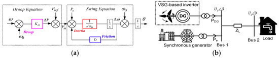
Figure 1.
Virtual synchronous generator (VSG) control block and two-machine infinite-bus system: (a) the control block of VSG; (b) the two-machine infinite-bus system.
The linearized model of power balance equation with an initial state at Bus 1 meets:
As traditional inverters lack inertia, the VSG control algorithm shown in Figure 1a is introduced to provide frequency and voltage support during power fluctuations. Combined with a droop strategy, the model for a VSG under yields:
Since traditional control of the DG is often working on a maximum power point tracking (MPPT) state, the active power output does not vary with a small disturbance on the grid side, indicating in Equation (1). When VSG control strategy is introduced, the output of the active power responses as grid frequency varies. Combined with Equations (1), (3) and (4), the linearized model with/without VSG control is expressed:
where . For the original system, the eigenvalues and damping ratio are calculated as:
For VSG, , . The inertia and droop coefficient of the system increase when VSG control is introduced. According to Equations (6) and (7), the damping ratio may decrease, and the eigenvalues may move from left to right when the parameters of multiple VSGs and SGs do not complement each other well. The unsuitable parameters of the system deteriorate stability margin and increase angle instability risk, which is unfavorable to the grid power oscillation.
Figure 2 gives a simple example of two VSG controllers operating in parallel. The eigenvalues of this simple system are calculated as the inertia and damping varies from their rated values to their limitations. The results show that the coordinated design needs to be introduced for multiple VSGs to obtain a better operational performance.
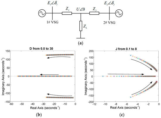
Figure 2.
Small-signal stability analysis results of two VSGs operating in parallel. (a) The network of two VSG system, (b) The eigenvalues of system as the inertia varies, (c) The eigenvalues of system as the damping varies.
2.2. Parameter Design Method for Multiple VSG in Improving Small-Signal Stability of System
Quite often, we want the system to operate with well-damped oscillations and keep robustness under disturbances [16]. For this motivation, the D-stable region [17] is presented here to let the eigenvalues of typical operating points lie in an area of secure operation. To enhance the damping ratio and stability margin of the system, this region is used to define a criterion for the controller design. Modes with higher damping behaviors stand on a complex plane shown in Figure 3. The performance robustness constraints for the design methodology is presented as follows:
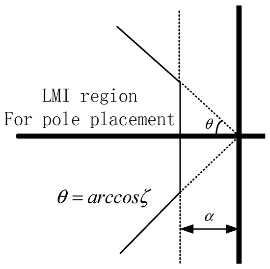
Figure 3.
D-stable area.
The proof of this theorem can be found in [17]. As the output of renewable generation is stochastic, the system under different operation states indicates the weak adaptability of the traditional certainty model. To guarantee the robustness of the converter and enhance dynamic response, a polytopic linear differential inclusion model is presented here for better expressing uncertainty in RES. Instead of precisely predicting system state in a period, the LDI only requires a motion-changed region of the uncontrolled resource in time [18]. This advantage provides a possibility to apply a stochastic forecast model to deal with the stability analysis with systematical prediction errors. According to its mathematical definition, the system based on PLDI is expressed as:
For a typical PLDI, the system has globally uniform stability when it satisfies an exponentially stable theorem [19]. This characteristic provides a possibility to apply PDLI theory to qualitatively judge the stability of the stochastic time-variant system and simplifies the analysis process of uncertainty disturbances. According to [19,20], the stability criterion for PLDI is given as follows:
Theorem 1.
Consider a composite positive function in Equation (11). A PDLI system is exponentially stable if and only if positive–definite matrices , , and , exist, such that
According to the Schur complement rule, Equation (12) is equal to:
The detail proving process of Equations (12) and (13) is found in [19]. In a practical circuit, is determined by the system operation requirement. The parameters and , according to [21], should satisfy:
Combined with the small-signal model of the VSG-based converter, the optimized issue considered stochastic excitation yields
In the practical project, we always want a larger than 0.05, which is called a strong damping mode. Then, let , and . The polytopic linear differential matrices Ai is:
When a polytopic model is considered, Equations (8) and (9) should be rewritten for each vertex system, and the resulting set of inequalities should be solved simultaneously to ensure all eigenvalues that lie in a designed region. The optimized issue expressed by Equation (15) consists of a family of bilinear matrix inequities (BMIs) that contain bilinear terms as the product of a full matrix and a scalar. To effectively solve the BMI problem and improve the applicability for large-scale systems, the path-following method [22] is adopted here to update all parameters.
3. Improved Coordinate-Adaptive J/D Control Strategy of Multiple VSGs in Mitigating OSC
3.1. The Mechanism of Improved Bang-Bang Control Strategy in Improving the Transient Stability of a System
Generally, the system needs to go through three intervals during transient disturbances before converging into a steady state [16]. This transition (i.e., a–b–c–b) shown in Figure 4a often inevitably causes power oscillation and deteriorates frequency damping. In contrast, as the rotor does not exist, the controller parameters of the VSG can be more flexible during the OSC cycle, hence accelerating the response of the VSG in tracking the steady state. For example, during the acceleration modes (i.e., a–b and c–b), high inertial parameters are adapted to resist disturbances, while small inertial parameters need to be chosen during the deceleration period (i.e., b–c and b–a) to accelerate convergence. This strategy was first introduced by [14,15] and represents one step further on how to detail the coordinate design of adaptive parameters (i.e., J and D) during each stage.
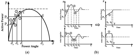
Figure 4.
The power-angle curve of a synchronous machine (SM) and the proposed VSG: (a) the SM response during transient disturbances; (b) the proposed VSG response during transient disturbances.
In fact, the intervals during the OSC cycle can be reduced into one interval (i.e., a–b) if the appropriate control strategy is utilized. For example, on the right side of Figure 4b, we usually want the frequency converges into a rated value at the same time t1 that the output of VSG increases to its final required power. This process requires the angular velocity to grow first and then decrease. If this scene happens, the other stages in the OSC cycle no longer exist, and the other transient adjustments of the system are eliminated. Specifically, when a large disturbance occurs, the angular frequency quickly increases and obtains its upper limit at time tu. According to Equation (4), during this period, the inertial term at the left side of the equation is larger than the damping term. The ω then remains with the fastest velocity and waits for the decreasing order. When the decline time td comes, the begins to decrease and the inertial term at the left side of the equation is smaller than the damping term. Finally, the will converge into its rated value at time t1, and the system operates steadily without any further adjustment. During this whole cycle, the output of the VSG remains increasing and reaches P2 at the same time t1. It needs to be emphasized that the output of the VSG rises linearly during periods between tu and td, and the is continuous but nondifferentiable during the whole time. Compared to SM, only the VSG is flexible enough to operate in this idea.
3.2. Parameter Design Method for Multiple VSG Corresponding to Oscillation Cycle
To begin with, we should set a trigger threshold that enables transient self-adaptive control. The threshold is determined by the endurance capacity and of the VSG-based converter. When the disturbance happens, the controller starts. Then, to fulfil the expectation in Figure 4b, the parameter-optimization issue, for one VSG, yields
The first equality constraint represents the required power deviation that is calculated by the terminal voltage and at the converter and grid side and the impedance between these two sides. The second equality term represents the steady-state constraint. The third and fourth constraints consider the limitation of the frequency change-rate threshold , e.g., the charge–discharge rate of the battery in the VSG-based converter and the maximum frequency deviation . According to the model in Equation (17) at a particular time , the constrains at the time-span in Figure 4b satisfies:
It is obvious that , and . Assume the same decline rate of frequency. Based on Equations (17) and (18), we have
If we know the final state of the system (i.e., is obtained), then is identified by Equation (19). Then, according to Equation (18), the term should meet the following condition:
Combined with Equations (4) and (20), parameters J and D during three periods should meet the following conditions:
(a) In a period , the frequency linearly increases as a rate of . Then at this stage, the parameters J should meet the following condition:
To accelerate this transient process, at this period.
(b) When the system meets , the system transits to Stage 2, and parameters should have
During this period, J is set as the original value.
(c) Then, in , the frequency linearly decreases as a rate of , and while J meets the following condition:
This control strategy can be applied to a single VSG-based system owing to the power fluctuation, and the adjustment is mainly provided by this converter. From Equations (17)–(19), to obtain the adjust time , the adjusting power should be identified. This situation indicates that the coordinated controller needs to obtain the next system steady state. However, for a multiple VSG-based system, the steady-state output of each VSG is not easy to achieve. For this concern, a system state estimation algorithm is needed.
Considering a typical AC network, the oscillation happens due to the power matching process between each SMs when a disturbance happens. When detecting the imbalance frequency between each bus, the SMs adjust their output for system synchronization. Subsequently, the frequency recovers to its rated value. This characteristic indicates that each VSG at the same bus should synchronize at any moment to eliminate OSC. Therefore, if each VSG introduces the proposed parameter-optimization issue, according to Equation (18), the deviation of the power angle is the same. Hence, the state estimation algorithm can utilize this characteristic to simplify the calculation procedure. Since the controller needs to obtain the final system state variable (i.e., voltage and active power), this estimation is somehow similar to static security analysis [23] after a disturbance.
For a typical network contained n bus, the system at each bus meets the following power balance constraints [23]:
In traditional power flow analysis, SM is set as a PV node, and a node is needed for power balancing. However, a VSG-based converter is not appropriate to be considered as a PV node, especially control is introduced. When system operates in an island model, the power balance between load and energy resource is maintained by adjusting converter output. Therefore, according to Equation (24), the VSG-based converter meets the following conditions:
The left side of Equation (25) represents the output of the VSG when line impedance meets . This requirement can be fulfilled by adding virtual impedance [24]. Hence, in Equation (25), , is set as the nominal integrated voltage. The equation contains two unknown variables (i.e., and ), which are consistent with traditional PQ node constraint. Then, based on Newton-Raphson, the Jacobian matrix yields
When , the next operation state is obtained by Equations (25) and (26) and the equality constraint of power angle on the same bus.
Equation (26) can be solved by the Newton-Raphan method in this case. The calculation speed can be faster if the system satisfies the constraints of the PQ decoupled method. Moreover, if the grid structure is fixed, the iterative matrix in Equation (26) is determined and only needs to generate once according to the PQ algorithm.
Noted that this calculation will cause a time-delay issue. From Equation (18), the controller satisfies , which is constant and identified by controller response ability. Therefore, the time-span at Stage 1 () is determined. This characteristic indicates that the time-delay issue can be eliminated if the measurement and calculation process can be done before time . From a practical perspective, the speed requirement can be fulfilled, especially for a large-scale power system containing Wide Area Measurement System (WAMS) equipment, e.g., Power Management Unit (PMU) [25].
The maximal power margin of each VSG is different, so the proposed method is limited by the minimum of the maximal adjust-margin of VSG-based converters. Let . Then, for a given system,
Equation (27) represents the maximal self-adjustment ability of a system, which is limited by each . If the strength of the disturbances exceeds the limitation of the system, the strategy in [15] is utilized in this paper.
In all, the steps for coordinate-adaptive J/D control of multiple VSGs is summarized as follows:
- (a)
- Measure the bus disturbances. If , go to Step (b);
- (b)
- Set the J/D value to satisfy the first-period requirement in Equation (21), while estimating the final state of the system by utilizing Equations (25) and (26) and equality constraint;
- (c)
- Transit J/D to the values in Equation (22) at time ; meanwhile, calculate and ;
- (d)
- At time , let the J/D value satisfy Equation (23) and return to their rate values.
4. Case Study
To validate the proposed approach, two test cases are utilized. The first case is a four-machine two-area test system shown in Figure 5a. In this case, each generator model has six generator states, and the additional control is not considered. The SMs in Areas 1 and 2 are replaced by two VSG-based converters with the equivalent MVA rating of the original SM. The specification and setting of VSGs are shown in Table 1, and the typical system operation data is supplied by [16]. To be mentioned, the VSG parameters J and D before optimization are consistent with the original SM in the same bus. The purpose of this setting is to prove that the VSG-based converter participates in the original electromechanical oscillation modes.
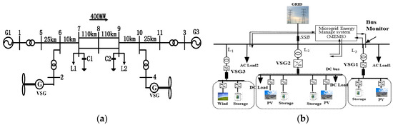
Figure 5.
Test cases system: (a) four-machine two-area system containing VSG; (b) a typical microgrid containing three VSGs.

Table 1.
Case 1: Main simulation parameters of the VSG model.
The second case is a typical Microgrid system shown in Figure 5b. The operation parameters, which were optimized by the PLDI and the D-stable model, are given in Table 2. The validation was carried out on a real-time digital simulator (RTDS) to validate the controller presented in Section 2. The model of the VSG and the proposed controller were built on RSCAD, which is accompanying software of RTDS. The signal connection of the RTDS simulation is shown in Figure 6. The digital output card (GTDO) and the digital input card (GTDI) was provided to generate a D/A signal for communication between the RTDS and controller platform. The Field Programmable Gate Array (FPGA, XC3S200-AN) and Digital Signal Processing (DSP, TMS-320F28335) constitute the main hardware architectures of a platform. The PWM pulse signal was provided by this platform.
Table 2.
Case 2: Main simulation parameters of the microgrid system.
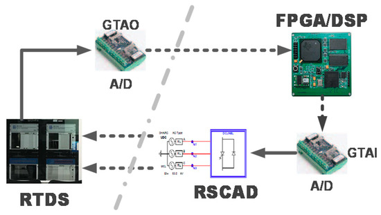
Figure 6.
The semi-physical platform of the microgrid based on the RTDS system.
4.1. Case 1 Study
Small-signal stability is of great importance for a system to perform well. To mitigate the power oscillation caused by VSGs, the Case 1 test system was mainly introduced to validate the coordinated parameter design method in Section 3. Compared with the traditional VSG controller [4], the stable margin and the dynamic response of the multiple-VSG system before and after optimization are presented here to show the advantages.
The dominant eigenvalues of the original two-area system, before and after optimization, are shown in Figure 7. The oscillation decays in all cases when a disturbance happens. However, the level of damping ratio of the original interarea model, i.e., ξ = 0.0341), is too small to be accepted. After replacing the SMs with a VSG-based converter station, the dominant eigenvalues shown in Figure 7 are changed and improved but still quite close to the original oscillation model. Since the VSG parameters J and D are consistent with the SM, the similarity of oscillation indicates that both VSGs and SMs are coupled, and parameter optimization of multiple VSGs needs to be considered. To satisfy operation requirement, the minimum ξ of the system is 0.05, and the physical constraints of the VSG converter are shown in Table 1. Based on the proposed designed method in Section 2.1, the dominant eigenvalues after optimization is also shown in Figure 7. The dynamic response to step changes of 2% with/without optimization are shown in Figure 8 and Figure 9.
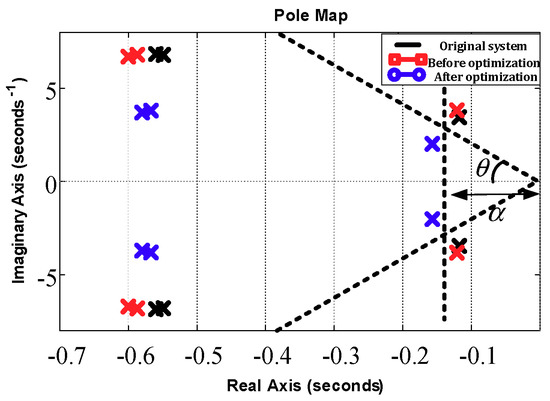
Figure 7.
The eigenvalues of the system before/after optimization.
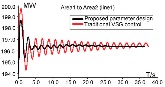
Figure 8.
Dynamic response of inter-area power before/after optimization.
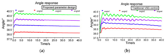
Figure 9.
Dynamic response of power angle before/after optimization. (a) After optimization, (b) before optimization.
In Figure 7, the eigenvalues are located in a specified complex plane that satisfies the design requirement, and the damping ratios of the system are all larger than 0.05. According to Figure 8 and Figure 9, the generator speed responses to changes in the mechanical torque decays fast when J/D parameters are designed. In contrast, the oscillation of the original system with insufficient ξ decays for more than 30 s. In addition, the simulation result shows the high tracking speed and small overshoot of the proposed algorithm.
4.2. Case 2 Study
To fully utilize the outstanding flexible and convenient performances of VSGs during oscillation, Case 2 was performed to validate the coordinate-adaptive method in Section 2. Compared with the constant J/D controller [4] and the traditional adaptive control [6], the effectiveness and advantage of the improved coordinate-adaptive J/D control strategy are verified.
Figure 10 gives the root locus of this test system as the inertia varies. The disturbance fluctuation margin is set as 10 kW, and related analyses are performed to assess the dynamic transient performance behaviors of the VSGs with the proposed coordinated strategy. The description of this case is as follows: At 0.5 s, there is a step change from 8 to 18 kW in the active power of AC Load1 in Figure 5b. Then, 2 s later, the load decreases to its rated value. The transient response of VSG-based converters is shown in Figure 11, Figure 12, Figure 13 and Figure 14 as follows.
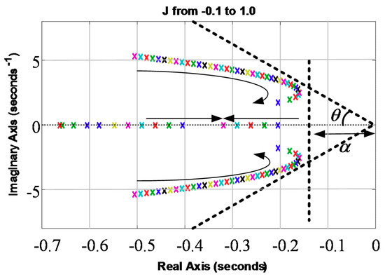
Figure 10.
The root locus of this test system with the J from −0.1 to 1.0.
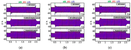
Figure 11.
Current responses among different controllers: (a) VSG1; (b) VSG2; (c) VSG3.
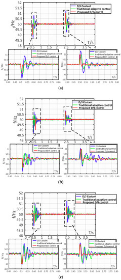
Figure 12.
Frequency response among different controllers: (a) VSG1; (b) VSG2; (c) VSG3.
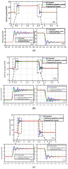
Figure 13.
Active power response among different controllers: (a) VSG1; (b) VSG2; (c) VSG3.
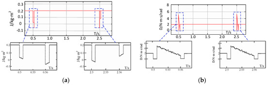
Figure 14.
The variation of virtual inertia and damping coefficient: (a) virtual inertia; (b) damping coefficient.
Figure 11, Figure 12 and Figure 13 shows the comparison of current, frequency, and active power among different control strategies at each VSG. Figure 14 is the changing process of adaptive virtual inertia and damping coefficients during transient response. According to Figure 11, Figure 12 and Figure 13, the coordinated controller is well able to control the system response during the sharp rise of power. During simulation, the overshoot under coordinated control is restricted to a small area and the settling time of the system is less than 0.01 s. The total transient period is less than 0.05 s. In contrast, the constant J and D control and traditional adaptive control [6] took longer to converge into the rated frequency. Meanwhile, the overshoot of the system under these controllers is higher than the proposed method. Moreover, the oscillating amplitude of frequency under constant J/D is larger than 1 Hz. The dynamic response of current and active power shown in Figure 11 and Figure 13 also demonstrates the advantages of the proposed method over the other controllers. The overshoot and total transient period under the proposed method are constricted to a small region, and the active power experiences a smooth transition to the final state.
In Figure 14, the adaptive dynamic process of parameters J and D are fitted to Equations (21)–(23). During the first period, according to Equation (21), parameter J satisfies a linearly decreasing function, while the linearly increases. The parameter D at Stage 2 is obviously linearly increasing. At Stage 3, parameter J shows a contrary tendency with a change in . It should be noted that the inertial parameter J is negative during this period to fast convergence.
Note that, since the structure of the microgrid is fixed and the network impedance satisfies , the PQ decoupled method can be utilized and the and can be directly and quickly identified using Equation (26). The proposed estimation algorithm is fast enough to calculate the threshold time T2 (in this case, it is 6 ms, according to Figure 14) before the controller requires. From the viewpoints of increasing the adaptability of the proposed controller and reducing the requirement of the measurement of the device’s ability, some follow-up work can be done, such as the improvement of the estimation algorithm with deep learning as well as reduced-order models of real-sized power systems.
5. Conclusions
This paper introduces a coordinated control for multiple virtual synchronous generators to improve small-signal stability. Simulation, utilizing a two-area four-machine system and a typical microgrid test system, validates the proposed strategy. Based on theoretical analysis and simulation study, the major conclusions include the following:
(1) The theoretical analysis and related simulation prove that the VSG-based converters are involved in the original electromagnetic oscillation mode. Hence, the damping ratio may decrease and the eigenvalues will move from left to right. The simulation result in Case 1 shows the high tracking speed and small overshoot and thus shows the effectiveness of the proposed algorithm.
(2) To further reduce dynamic periods during transient disturbances, an optimization algorithm for the coordinated controlling of multiple VSG-based converters is presented. Compared to the constant J and D control and traditional adaptive control, the advanced controller can well reduce overshoot and oscillating amplitude in Case 2.
The results effectively confirm the applicability of the method and indicates the benefits of the proposed strategy in enhancing operation stability and the anti-disturbing ability of multiple VSGs. Concerning the proposed coordinated control, a few aspects should be enriched, and these include reducing and optimizing the investment of a detection system. Moreover, a coping strategy responding to asymmetric faults is necessary. These tasks will be carried out in the future.
Author Contributions
P.H. helped design the study, analyze the data, and write the manuscript. H.C. helped conduct the study. K.C. helped analyze the data. Y.H. helped draw the figure. D.K. helped draft the manuscript. L.C. helped conduct the simulation analysis. Y.W. helped edit the manuscript.
Funding
This research was funded by the National Science Foundation of China, grant number 510507117
Conflicts of Interest
The authors declare no conflicts of interest.
Nomenclature
| Subscript | integer index = {1, 2, 3, ……}. |
| Subscript | presents the synchronous machine (SM). |
| Subscript , DG | presents the distribution generation (DG). |
| , | the voltage at bus 1 and bus 2 respectively. |
| impedance between bus 1 and bus 2. | |
| , | the electromagnetic power and supply power of SM. |
| , | operational and rated rotor angular velocity. |
| , , | virtual inertia, damping coefficient, and droop coefficient of VSG. |
| symmetric matrix of linear matrix inequality (LMI) variables. | |
| a typical convex hull function which meets , . | |
| , | designer specified scalar values shown in Figure 3. |
| , , , | the state, input variable and constant matrices of the system. |
| , , | the required phase margin, cut-off frequency and max droop of VSG. |
| , , | the damping ratio threshold and response time-span of the system, . |
| , | the real and imaginary parts of an element in nodal admittance matrix. |
| , | the net active and reactive power at node i. |
References
- Kozlova, M. Real option valuation in renewable energy literature: Research focus, trends and design. Renew. Sustain. Energy Rev. 2017, 80, 180–196. [Google Scholar] [CrossRef]
- Miller, N.; Loutan, C.; Shao, M.; Clark, K. Emergency response: US system frequency with high wind penetration. IEEE Power Energy Mag. 2013, 6, 63–71. [Google Scholar] [CrossRef]
- Collins, S.; Deane, J.P.; Poncelet, K.; Panos, E.; Pietzcker, R.C. Integrating short term variations of the power system into integrated energy system models: A methodological review. Renew. Sustain. Energy Rev. 2017, 76, 839–856. [Google Scholar] [CrossRef]
- Zhong, Q.C.; Hornik, T. Synchronverters: Grid-friendly inverters that mimic synchronous generators. IEEE Trans. Ind. Electron. 2011, 58, 1259–1267. [Google Scholar] [CrossRef]
- Karimi-Ghartemani, M.; Khajehoddin, S.A.; Piya, P.; Ebrahimi, M. Universal controller for three-phase inverters in a microgrid. IEEE J. Emerg. Sel. Top. Power Electron. 2016, 4, 1342–1353. [Google Scholar] [CrossRef]
- Shintai, T.; Miura, Y.; Ise, T. Oscillation damping of a distributed generator using a virtual synchronous generator. IEEE Trans. Power Deliv. 2014, 29, 668–676. [Google Scholar] [CrossRef]
- Guan, M.; Pan, W.; Zhang, J.; Hao, Q.; Cheng, J. Synchronous generator emulation control strategy for voltage source converter (vsc) stations. IEEE Trans. Power Syst. 2015, 30, 3093–3101. [Google Scholar] [CrossRef]
- Xi, X.; Geng, H.; Yang, G. Small signal stability of weak power system integrated with inertia tuned large scale wind farm. In Proceedings of the IEEE PES Innovative Smart Grid Technologies (ISGT), Washington, DC, USA, 19–22 February 2014; pp. 514–518. [Google Scholar]
- Eftekharnejad, S.; Vittal, V.; Heydt, G.T.; Keel, B.; Loehr, J. Impact of increased penetration of photovoltaic generation on power systems. IEEE Trans. Power Syst. 2013, 28, 893–901. [Google Scholar] [CrossRef]
- Gautam, D.; Vittal, V.; Harbour, T. Impact of increased penetration of DFIG-based wind turbine generators on transient and small signal stability of power systems. IEEE Trans. Power Syst. 2009, 24, 1426–1434. [Google Scholar] [CrossRef]
- Quintero, J.; Vittal, V.; Heydt, G.T.; Zhang, H. The impact of increased penetration of converter control-based generators on power system modes of oscillation. IEEE Trans. Power Syst. 2015, 29, 2248–2256. [Google Scholar] [CrossRef]
- Ma, J.; Qiu, Y.; Li, Y.; Zhang, W.; Song, Z. Research on the impact of dfig virtual inertia control on power system small-signal stability considering the phase-locked loop. IEEE Trans. Power Syst. 2017, 32, 2094–2105. [Google Scholar] [CrossRef]
- Torres L., M.A.; Lopes, L.A.C.; Morán T., L.A.; Espinoza C., J.R. Self-tuning virtual synchronous machine: A control strategy for energy storage systems to support dynamic frequency control. IEEE Trans. Energy Convers. 2014, 29, 833–840. [Google Scholar] [CrossRef]
- Alipoor, J.; Miura, Y.; Ise, T. Power system stabilization using virtual synchronous generator with alternating moment of inertia. IEEE J. Emerg. Sel. Top. Power Electron. 2015, 3, 451–458. [Google Scholar] [CrossRef]
- Li, D.; Zhu, Q.; Lin, S.; Bian, X.Y. A self-adaptive inertia and damping combination control of vsg to support frequency stability. IEEE Trans. Energy Convers. 2017, 32, 397–398. [Google Scholar] [CrossRef]
- Rogers, G. Power System Oscillations; Kluwer Academic Publishers: Norwell, MA, USA, 2000. [Google Scholar]
- Chilali, M.; Gahinet, P. H∞ design with pole placement constraints: A LMI approach. IEEE Trans. Autom. Control 1996, 4, 358–367. [Google Scholar] [CrossRef]
- Smirnov, G.V. Introduction to the theory of differential inclusions. Am. Math. Soc. 2002, 255, 114–139. [Google Scholar]
- Hu, T.; Lin, Z. Properties of the composite quadratic Lyapunov functions. IEEE Trans. Autom. Control 2004, 49, 1162–1167. [Google Scholar] [CrossRef]
- Pham, H.; Jung, H.; Hu, T. State-space approach to modeling and ripple reduction in ac–dc converters. IEEE Trans. Control Syst. Technol. 2013, 21, 1949–1955. [Google Scholar] [CrossRef]
- Wu, H.; Ruan, X.; Yang, D.; Chen, X.; Zhao, W. Small-signal modeling and parameters design for virtual synchronous generators. IEEE Trans. Ind. Electron. 2016, 63, 4292–4303. [Google Scholar] [CrossRef]
- Hassibi, A.; How, J.; Boyd, S. A path-following method for solving BMI problems in control. In Proceedings of the American Control Conference, Anchorage, AK, USA, 8–10 May 2002; Volume 2, pp. 1385–1389. [Google Scholar]
- Sauer, P.W.; Pai, M.A. Power System Dynamics and Stability; Prentice-Hall: Englewood Cliffs, NJ, USA, 1998. [Google Scholar]
- Pogaku, N.; Prodanovic, M.; Green, T.C. Modeling, analysis and testing of autonomous operation of an inverter-based microgrid. IEEE Trans. Power Electron. 2007, 22, 613–625. [Google Scholar] [CrossRef]
- Bevrani, H.; Watanabe, M.; Mitani, Y. Power System Monitoring and Control; John Wiley & Sons: Hoboken, NJ, USA, 2014. [Google Scholar]


© 2018 by the authors. Licensee MDPI, Basel, Switzerland. This article is an open access article distributed under the terms and conditions of the Creative Commons Attribution (CC BY) license (http://creativecommons.org/licenses/by/4.0/).