Optical Fiber Temperature Sensors and Their Biomedical Applications


Abstract
1. Introduction
- ◦
- The application: temperature, strain, displacement, current, magnetic fields, pressure, torsion, bending, vibration, humidity, lateral load, refractive index, detection of bio-molecules or chemical species [4].
- ◦
- The measurable spatial scope: point sensors, quasi-distributed sensors, and fully distributed sensors [6].
- ◦
- The modulation process: intensity, phase, state of polarization, and wavelength shift (frequency) [4].
- ◦
- The working principle: optical fiber gratings (fiber Bragg grating (FBG), chirped fiber Bragg grating, tilted fiber Bragg grating (TFBG) and long period grating), interferometry (Fabry-Pérot (FP), Mach-Zehnder, Michelson, Sagnac, high birefringence fiber loop mirror sensors, and multimode interferometer) [7,8,9,10], distributed sensors (Raman scattering, Rayleigh scattering and Brillouin scattering) [8], or polarization-optical time domain reflectometry sensors [11,12].
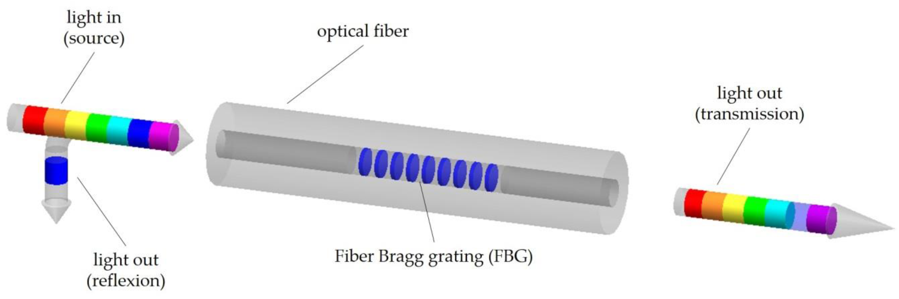
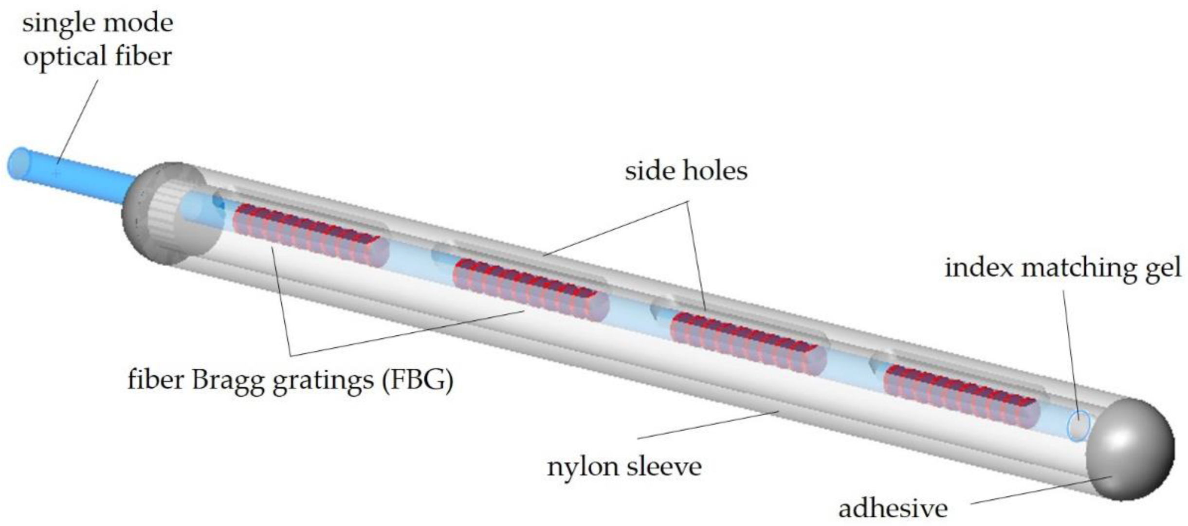
1.1. Fiber Bragg Grating
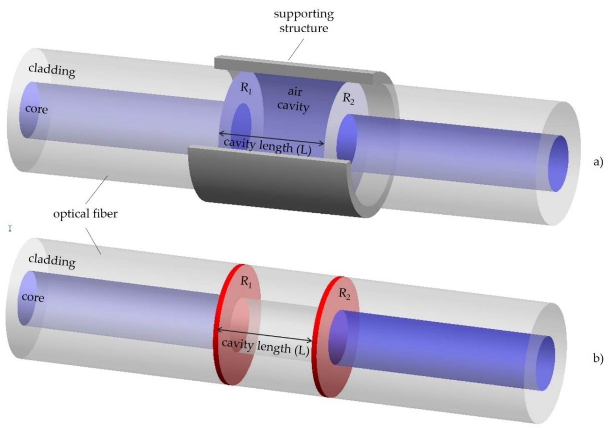
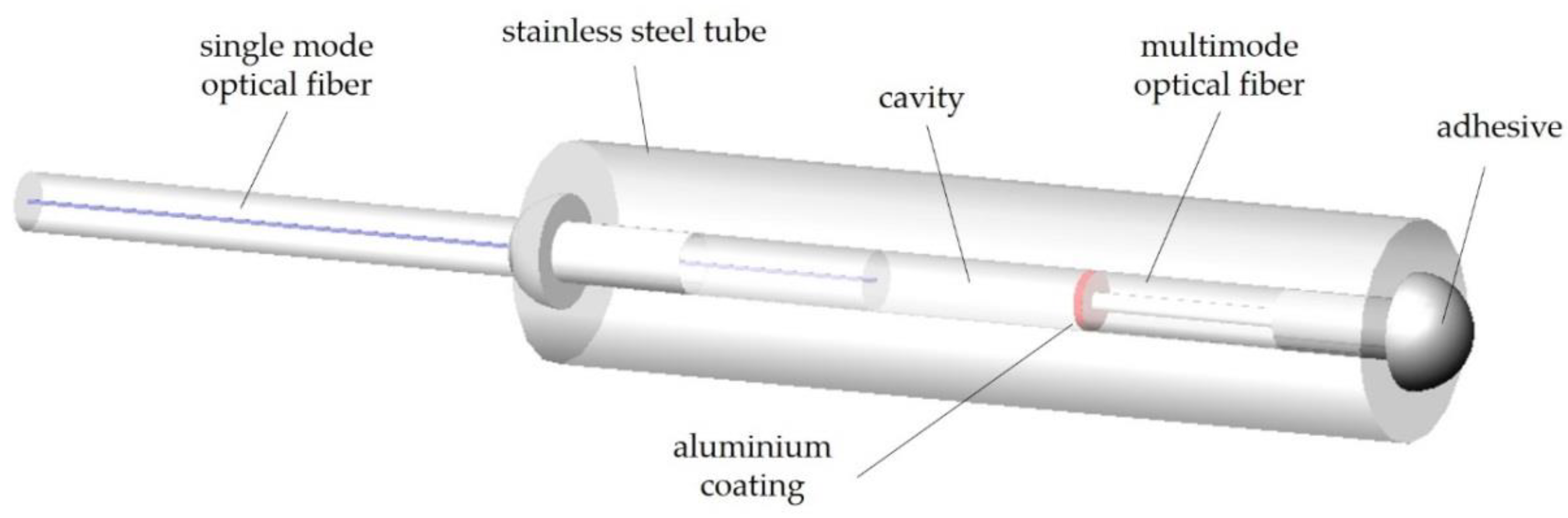
1.2. Fabry-Pérot Interferometers
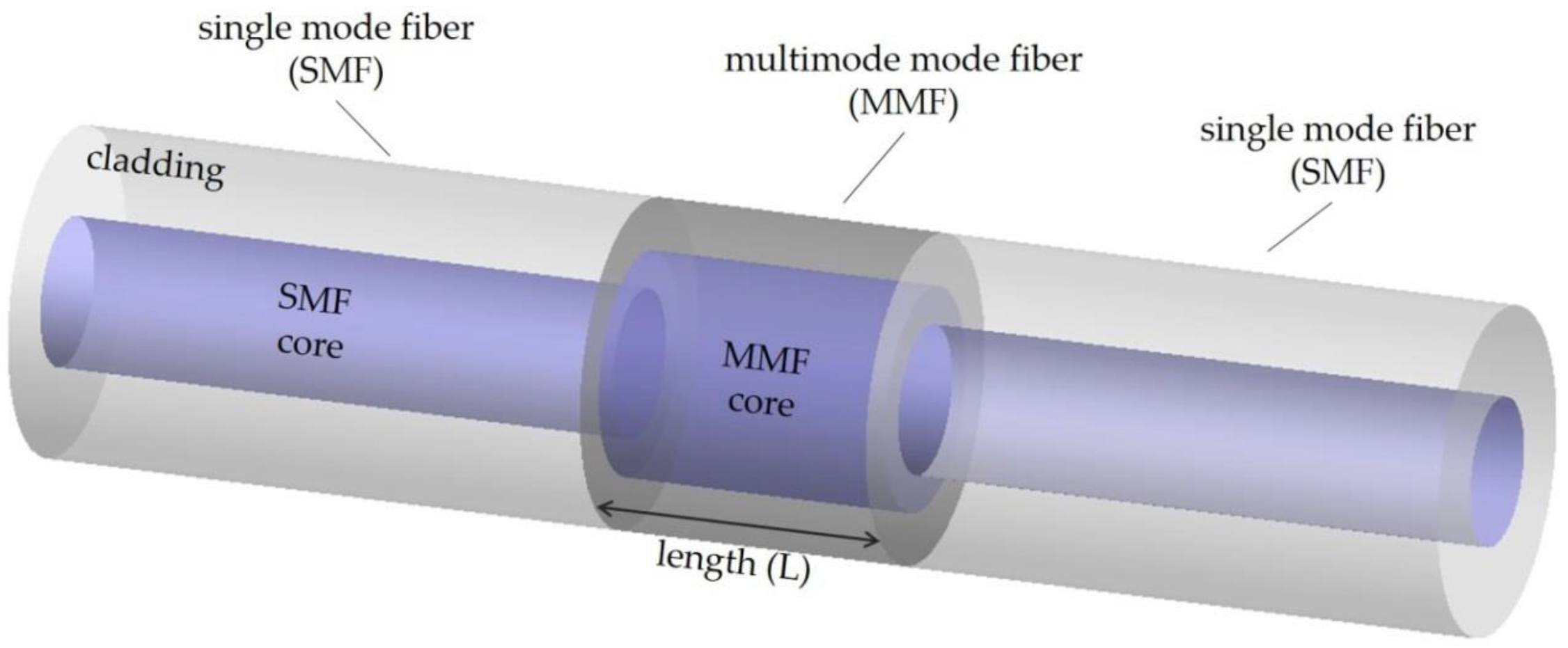
1.3. Multimode Fiber Interferometers Sensors
2. Biomedical Optical Fiber Temperature Sensors
3. Final Remarks
Author Contributions
Funding
Acknowledgments
Conflicts of Interest
References
- Novais, S. Optical Fiber Sensors for Challenging Media. Ph.D. Thesis, University of Aveiro, Aveiro, Portugal, 2019. [Google Scholar]
- Udd, E.; Spillman, W.B. Fiber Optic Sensors: An Introduction for Engineers and Scientists; John Wiley Sons: New York, NY, USA, 2011. [Google Scholar]
- Hisham, H.K. Optical Fiber Sensing Technology: Basics, Classifications and Applications. Am. J. Remote Sens. 2018, 6, 1–5. [Google Scholar] [CrossRef]
- Fidanboylu, K.; Efendioglu, H.S. Fiber optic sensors and their applications. In Proceedings of the 5th International Advanced Technologies Symposium, Karabuk, Turkey, 13–15 May 2009. [Google Scholar]
- Kersey, A.D. A review of recent developments in fiber optic sensor Technology. Opt. Fiber Technol. 1996, 2, 291–317. [Google Scholar] [CrossRef]
- Joe, H.E.; Yun, H.; Jo, S.H.; Jun, M.B.G.; Min, B.K. Review on optical fiber sensors for environmental monitoring. Int. J. Precis. Eng. Manuf.-Green Technol. 2018, 5, 173–191. [Google Scholar] [CrossRef]
- Lee, C.E.; Taylor, H.F.; Markus, A.M.; Udd, E. Optical-fiber Fabry-Pérot embedded sensor. Opt. Lett. 1989, 14, 1225–1227. [Google Scholar] [CrossRef] [PubMed]
- Raffaella, D.S. Fibre optic sensors for structural health monitoring of aircraft composite structures: Recent advances and applications. Sensors 2015, 15, 18666–18713. [Google Scholar]
- Frazão, O.; Baptista, J.M.; Santos, J.L. Recent advances in high-birefringence fiber loop mirror sensors. Sensors 2007, 7, 2970–2983. [Google Scholar] [CrossRef] [PubMed]
- Dong, B.; Wei, L.; Zhou, D.P. Miniature high-sensitivity high-temperature fiber sensor with a dispersion compensation fiber-based interferometer. Appl. Opt. 2009, 48, 6466–6469. [Google Scholar] [CrossRef]
- Juarez, J.C.; Taylor, H.F. Polarization discrimination in a phase-sensitive optical time-domain reflectometer intrusion-sensor system. Opt. Lett. 2005, 30, 3284–3286. [Google Scholar] [CrossRef]
- Juarez, J.C.; Taylor, H.F. Field test of a distributed fiber-optic intrusion sensor system for long perimeters. Appl. Opt. 2007, 46, 1968–1971. [Google Scholar] [CrossRef]
- Hoffmann, L.; Müeller, M.S.; Krämer, S.; Giebel, M.; Schwotzer, G.; Wieduwilt, T. Applications of fibre optic temperature measurement. Proc. Estonian Acad. Sci. Eng. 2007, 13, 363–378. [Google Scholar]
- Li, X.; Lin, S. Fiber–optic temperature sensor based on difference of thermal expansion coefficient between fused silica and metallic materials. IEEE Photonics J. 2012, 4, 155–162. [Google Scholar]
- Hernández-Romano, I.; Cruz-Garcia, M.A.; Moreno-Hernández, C.; Monzón-Hernández, D.; López-Figueroa, E.O.; Paredes-Gallardo, O.E.; Torres-Cisneros, M.; Villatoro, J. Optical fiber temperature sensor based on a microcavity with polymer overlay. Opt. Express 2016, 24, 5654–5661. [Google Scholar] [CrossRef] [PubMed]
- Kou, J.; Qiu, S.; Xu, F.; Lu, Y. Demonstration of a compact temperature sensor based on first-order Bragg grating in a tapered fiber probe. Opt. Express 2011, 19, 18452–18457. [Google Scholar] [CrossRef] [PubMed]
- Jung, J.; Nam, H.; Lee, B.; Byun, J.O.; Kim, N.S. Fiber Bragg grating temperature sensor with controllable sensitivity. Appl. Opt. 1999, 38, 2752–2754. [Google Scholar] [CrossRef] [PubMed]
- Zhao, Y.; Deng, Z.Q.; Hu, H.F. Fiber-optic SPR Sensor for temperature measurement. IEEE Trans. Instrum. Meas. 2015, 64, 3099–3104. [Google Scholar] [CrossRef]
- Luan, N.; Wang, R.; Lv, W.; Lu, Y.; Yao, J. Surface plasmon resonance temperature sensor based on photonic crystal fibers randomly filled with silver nanowires. Sensors 2014, 14, 16035–16045. [Google Scholar] [CrossRef] [PubMed]
- Lee, D.R.; Jang, S.W.; Kwon, D.H.; Kang, S.W. Side-polished fiber optic temperature sensor using a prism and fiber-to-planar waveguide coupler. Microw. Opt. Technol. Lett. 2005, 46, 523–525. [Google Scholar] [CrossRef]
- Jung, W.G.; Kim, S.W.; Kim, K.T.; Kim, E.S.; Kang, S.W. High sensitivity temperature sensor using a side-polished single-mode fiber covered with the polymer planar waveguide. IEEE Photonics Technol. Lett. 2001, 13, 1209–1211. [Google Scholar] [CrossRef]
- Zou, L.; Bao, X.; Chen, L. Distributed brillouin temperature sensing in photonic crystal fiber. Smart Mater. Struct. 2005, 14, S8. [Google Scholar] [CrossRef]
- Ju, J.; Jin, W. Photonic crystal fiber sensors for strain and temperature measurement. J. Sens. 2009, 2009, 476267. [Google Scholar] [CrossRef]
- Coviello, G.; Finazzi, V.; Villatoro, J.; Pruneri, V. Thermally stabilized PCF–based sensor for temperature measurements up to 1000 °C. Opt. Express 2009, 17, 21551–21559. [Google Scholar] [CrossRef] [PubMed]
- Li, C.; Liu, Q.; Peng, X.; Fan, S. Analyzing the temperature sensitivity of Fabry–Pérot sensor using multilayer graphene diaphragm. Opt. Express 2015, 23, 27494–27502. [Google Scholar] [CrossRef] [PubMed]
- Lee, C.L.; Lee, L.H.; Hwang, H.E.; Hsu, J.M. Highly sensitive air– gap fiber Fabry–Pérot interferometers based on polymer–filled hollow cathode fibers. IEEE Photonics Technol. Lett. 2012, 24, 149–151. [Google Scholar] [CrossRef]
- Li, X.; Shao, Y.; Yu, Y.; Zhang, Y.; Wei, S. A highly sensitive fiber– optic Fabry–Pérot interferometer based on internal reflection mirrors for refractive index measurement. Sensors 2016, 16, 794. [Google Scholar] [CrossRef] [PubMed]
- Kim, D.W.; Shen, F.; Chen, X.; Wang, A. Simultaneous measurement of refractive index and temperature based on a reflection mode long–period grating and an intrinsic Fabry–Pérot interferometer sensor. Opt. Lett. 2005, 30, 3000–3002. [Google Scholar] [CrossRef] [PubMed]
- Zhang, G.; Yang, M.; Wang, M. Large temperature sensitivity of fiber optic extrinsic Fabry–Pérot interferometer based on polymer–filled glass capillary. Opt. Fiber Technol. 2013, 19, 618–622. [Google Scholar] [CrossRef]
- Lin, H.Y.; Huang, C.H.; Cheng, G.L.; Chen, N.K.; Chui, H.C. Tapered optical fiber sensor based on localized surface plasmon resonance. Opt. Express 2012, 20, 21693–21701. [Google Scholar] [CrossRef]
- Alvarez-Chavez, J.A.; Perez-Sanchez, G.G.; Ceballes-Herrera, D.E.; Rodriguez-Rodriguez, J.H.; Schreiber, T. Temperature sensing characteristics of tapered Yb-doped fiber amplifiers. Optik 2013, 124, 5818–5822. [Google Scholar] [CrossRef]
- Bosch, M.E.; Sánchez, A.J.R.; Ojeda, C.B. Recent development in optical fiber biosensors. Sensors 2007, 7, 797–859. [Google Scholar] [CrossRef]
- Cennamo, N.; Massarotti, D.; Conte, L.; Zeni, L. Low cost sensors based on SPR in a plastic optical fiber for biosensor implementation. Sensors 2011, 11, 11752–11760. [Google Scholar] [CrossRef]
- Cennamo, N.; Chiavaioli, F.; Trono, C.; Tombelli, S.; Giannetti, A.; Baldini, F.; Zeni, L. A complete optical sensor system based on a POF-SPR platform and a thermo-stabilized flow cell for biochemical applications. Sensors 2016, 16, 196. [Google Scholar] [CrossRef]
- Hill, K.O.; Fuji, Y.; Johnson, D.C.; Kawasaki, B.S. Photosensitivity in optical fiber waveguides: Application to reflection filter fabrication. Appl. Phys. Lett. 1978, 32, 647–649. [Google Scholar] [CrossRef]
- Rao, Y.J. Fiber Bragg Grating Sensors: Principles and Applications; Grattan, K.T.V., Meggitt, B.T., Eds.; Chapman & Hall: London, UK, 1988; pp. 355–398. [Google Scholar]
- Lee, C.E.; Taylor, H.F. Sensors for smart structures based upon the Fabry-Pérot interferometer. In Fiber Optic Smart Structures; John Wiley & Sons, Inc.: New York, NY, USA, 1995; pp. 249–269. [Google Scholar]
- Yoshino, T.; Kurosawa, K.; Itoh, K.; Ose, T. Fiber-optic Fabry-Pérot interferometer and its sensor applications. IEEE Trans. Microw. Theory Technol. 1982, 30, 1612–1621. [Google Scholar] [CrossRef]
- Lee, B.H.; Kim, Y.H.; Park, K.S.; Eom, J.B.; Kim, M.J.; Rho, B.S.; Choi, H.Y. Interferometric fiber optic sensors. Sensors 2012, 12, 2467–2486. [Google Scholar] [CrossRef] [PubMed]
- Tsai, W.H.; Lin, C.J. A novel structure for the intrinsic Fabry-Pérot fiber-optic temperature sensor. J. Light. Technol. 2001, 19, 682–686. [Google Scholar] [CrossRef]
- Kim, S.H.; Lee, J.J.; Lee, D.C.; Kwon, I.B. A study on the development of transmission-type extrinsic Fabry-Perot interferometric optical fiber sensor. J. Light. Technol. 1999, 17, 1869–1874. [Google Scholar]
- Rao, Y.J. Recent progress in fiber-optic extrinsic Fabry-Pérot interferometric sensors. Opt. Fiber Technol. 2006, 12, 227–237. [Google Scholar] [CrossRef]
- Hunger, D.; Steinmetz, T.; Colombe, Y.; Deutsch, C.; Hansch, T.W.; Reichel, J. A fiber Fabry-Pérot cavity with high finesse. New J. Phys. 2010, 12, 1–24. [Google Scholar] [CrossRef]
- Ran, J.; Rao, Y.; Zhang, J.; Liu, Z.; Xu, B. A miniature fiber-optic refractive-index sensor based on laser machined Fabry-Pérot interferometer tip. J. Light. Technol. 2009, 27, 5426–5429. [Google Scholar]
- Rao, Y.J.; Deng, M.; Duan, D.W.; Yang, X.C.; Zhu, T.; Cheng, C.H. Micro Fabry-Pérot interferometers in silica fibers machined by femtosecond laser. Opt. Express 2007, 5, 14123–14128. [Google Scholar] [CrossRef]
- Ran, Z.L.; Rao, Y.J.; Liu, W.J.; Liao, X.; Chiang, K.S. Laser-micro machined Fabry-Pérot optical fiber tip sensor for high-resolution temperature-independent measurement of refractive index. Opt. Express 2008, 16, 2252–2263. [Google Scholar] [CrossRef] [PubMed]
- Wei, T.; Han, Y.; Tsai, H.L.; Xiao, H. Miniaturized fiber inline Fabry-Pérot interferometer fabricated with a femtosecond laser. Opt. Lett. 2008, 33, 536–538. [Google Scholar] [CrossRef] [PubMed]
- Wan, X.; Taylor, H.F. Intrinsic fiber Fabry-Pérot temperature sensor with fiber Bragg grating mirrors. Opt. Lett. 2002, 27, 1388–1390. [Google Scholar] [CrossRef]
- Wang, Z.; Shen, F.; Song, L.; Wang, X.; Wang, A. Multiplexed fiber Fabry-Pérot interferometer sensors based on ultrashort Bragg gratings. IEEE Photonics Technol. Lett. 2007, 19, 622–624. [Google Scholar] [CrossRef]
- Zhang, Y.; Chen, X.; Wang, Y.; Cooper, K.L.; Wang, A. Microgap multicavity Fabry-Pérot biosensor. J. Light. Technol. 2007, 25, 1797–1804. [Google Scholar] [CrossRef]
- Machavaram, V.R.; Badcock, R.A.; Fernando, G.F. Fabrication of intrinsic fibre Fabry-Pérot sensors in silica using hydrofluoric acid etching. Sens. Actuators A 2007, 138, 248–260. [Google Scholar] [CrossRef]
- Liu, S.; Wang, Y.P.; Liao, C.R.; Wang, G.J.; Li, Z.Y.; Wang, Q.; Zhou, J.T.; Yang, K.M.; Zhong, X.Y.; Zhao, J.; et al. High-sensitivity strain sensor based on in-fiber improved Fabry-Pérot interferometer. Opt. Lett. 2014, 39, 2121–2124. [Google Scholar] [CrossRef]
- Zhao, J.R.; Huang, X.G.; He, W.X.; Chen, J.H. High-resolution and temperature-insensitive fiber optic refractive index sensor based on Fresnel reflection modulated by Fabry-Pérot interference. J. Light. Technol. 2010, 28, 2799–2803. [Google Scholar] [CrossRef]
- Morris, P.; Hurrell, A.; Shaw, A.; Zhang, E.; Beard, P. A Fabry-Pérot fiber-optic ultrasonic hydrophone for the simultaneous measurement of temperature and acoustic pressure. J. Acoust. Soc. Am. 2009, 125, 3611–3622. [Google Scholar] [CrossRef]
- Jedrzewska-Szczerska, M.; Wierzba, P.; Chaaya, A.; Bechelany, M.; Miele, P.; Viter, R.; Mazikowski, A.; Karpienko, K.; Wróbel, M.; Mazikowski, A. ALD thin ZnO layer as an active medium in a fiber-optic Fabry-Perot interferometer. Sens. Actuators A 2015, 221, 84–89. [Google Scholar] [CrossRef]
- Jin, L.; Guan, B.O.; Wei, H.F. Sensitivity characteristics of Fabry-Pérot pressure sensors based on hollow-core microstructured fibers. J. Light. Technol. 2013, 31, 2526–2532. [Google Scholar]
- Ferreira, M.S.; Bierlich, J.; Kobelke, J.; Pinto, J.L.; Schuster, K.; Wondraczec, K. Hybrid sensor based on microstrutured hollow core fiber for simultaneous measurement of strain and temperature. In Photonic Instrumentation Engineering VI; International Society for Optics and Photonics: San Francisco, CA, USA, 2019; Volume 10925, p. 109250Z. [Google Scholar]
- Novais, S.; Ferreira, M.S.; Pinto, J.L. Lateral Load Sensing With an Optical Fiber Inline Microcavity. IEEE Photonics Technol. Lett. 2017, 29, 1502–1505. [Google Scholar] [CrossRef]
- Lee, C.L.; Chang, H.J.; You, Y.W.; Chen, G.H.; Hsu, J.M.; Horng, J.S. Fiber Fabry-Pérot interferometers based on air-bubbles/liquid in hollow core fibers. IEEE Photonics Technol. Lett. 2014, 26, 749–752. [Google Scholar] [CrossRef]
- Lee, C.L.; Ho, H.Y.; Gu, J.H.; Yeh, T.Y.; Tseng, C.H. Dual hollow core fiber-based Fabry–Pérot interferometer for measuring the thermo-optic coefficients of liquids. Opt. Lett. 2015, 40, 459–462. [Google Scholar] [CrossRef] [PubMed]
- Sun, B.; Wang, Y.; Qu, J.; Liao, C.; Yin, G.; He, J.; Zhou, J.; Tang, J.; Liu, S.; Li, Z.; et al. Simultaneous measurement of pressure and temperature by employing Fabry-Pérot interferometer based on pendant polymer droplet. Opt. Express 2015, 23, 1906–1911. [Google Scholar] [CrossRef] [PubMed]
- Liu, S.; Yang, K.M.; Wang, Y.P.; Qu, J.L.; Liao, C.R.; He, J.; Li, Z.Y.; Yin, G.L.; Sun, B.; Zhou, J.T.; et al. High-sensitivity strain sensor based on in-fiber rectangular air bubble. Sci. Rep. 2015, 5, 1–7. [Google Scholar] [CrossRef]
- Liu, G.G.; Han, M.; Hou, W.L. High-resolution and fast-response fiber-optic temperature sensor using silicon Fabry-Pérot cavity. Opt. Express 2015, 23, 7237–7247. [Google Scholar] [CrossRef]
- Liu, T.G.; Yin, J.D.; Jiang, J.F.; Liu, K.; Wang, S.; Zou, S.L. Differential-pressure-based fiber-optic temperature sensor using Fabry-Pérot interferometry. Opt. Lett. 2015, 40, 1049–1052. [Google Scholar] [CrossRef]
- Costa, G.K.B.; Gouvêa, P.M.P.; Soares, L.M.B.; Pereira, J.M.B.; Favero, F.; Braga, A.M.B.; Muhoray, P.P.; Bruno, A.C.; Carvalho, I.C.S. In-fiber Fabry-Perot interferometer for strain and magnetic field sensing. Opt. Express 2016, 24, 14690–14696. [Google Scholar] [CrossRef]
- Liu, H.; Yanga, H.Z.; Qiao, X.; Hu, M.; Feng, Z.; Wang, R.; Rong, Q.; Gunawarden, D.S.; Lim, K.S.; Ahmad, H. Strain measurement at high temperature environment based on Fabry-Perot interferometer cascaded fiber regeneration grating. Sens. Actuators A 2016, 248, 199–205. [Google Scholar] [CrossRef]
- Liu, X.; Jiang, M.; Sui, Q.; Song, F. Temperature sensitivity characteristics of HCPCF-based Fabry–Pérot interferometer. Opt. Commun. 2016, 359, 322–328. [Google Scholar] [CrossRef]
- Chen, W.P.; Wang, D.N.; Xu, B.; Zhao, C.L.; Chen, H.F. Multimode fiber tip Fabry-Pérot cavity for highly sensitive pressure Measurement. Sci. Rep. 2017, 368, 1–6. [Google Scholar] [CrossRef] [PubMed]
- Tian, J.; Jiao, Y.; Ji, S.; Dong, X.; Yao, Y. Cascaded-cavity Fabry-Pérot interferometer for simultaneous measurement of temperature and strain with cross-sensitivity compensation. Opt. Commun. 2018, 412, 121–126. [Google Scholar] [CrossRef]
- Chen, P.; Shu, X. Refractive-index-modified-dot Fabry-Pérot fiber probe fabricated by femtosecond laser for high-temperature sensing. Opt. Express 2018, 26, 5292–5299. [Google Scholar] [CrossRef]
- Liu, S.; Ji, Y.; Yang, J.; Sun, W.; Li, H. Nafion film temperature/humidity sensing based on optical fiber Fabry-Pérot interference. Sens. Actuators A 2018, 269, 313–321. [Google Scholar] [CrossRef]
- Liu, Y.; Wang, Y.; Yang, D.; Wu, J.; Zhang, T.; Yu, D.; Jia, Z.; Fu, H. Hollow-core fiber based all-fiber FPI sensor for simultaneous measurements of air pressure and temperature. Sens. J. 2019, 19, 11236–11241. [Google Scholar] [CrossRef]
- He, Y.; Yang, H.; Lim, K.; Ahmad, H.; Feng, Z.; Zhang, P.; Tian, Q.; Lu, K.; Han, Z.; Liu, J. Discriminative measurement for temperature and humidity using hollow-core Fabry-Pérot interferometer. Opt. Fiber Technol. 2019, 53, 102027. [Google Scholar] [CrossRef]
- Chen, M.Q.; Zhao, Y.; Wei, H.M.; Krishnaswamy, S. Cascaded FPI/LPFG interferometer for high-precision simultaneous measurement of strain and temperature. Opt. Fiber Technol. 2019, 53, 102025. [Google Scholar] [CrossRef]
- Yang, D.; Liu, Y.; Wang, Y.; Zhang, T.; Shao, M.; Yu, D.; Fu, H. Integrated optic-fiber sensor based on enclosed EFPI and structural phaseshift for discriminating measurements of temperature, pressure and RI. Opt. Laser Technol. 2020, 126, 106112. [Google Scholar] [CrossRef]
- Zhang, C.; Fu, S.; Tang, M.; Liu, D. Parallel Fabry-Pérot interferometers fabricated on multicore-fiber for temperature and strain discriminative sensing. Opt. Express 2020, 28, 3190–3198. [Google Scholar] [CrossRef]
- Nan, T.; Liu, B.; Wu, Y.; Wang, J.; Mao, Y.; Zhao, L.; Sun, T.; Wang, J.; Zhao, D. High-temperature fiber sensor based two paralleled fiber-optic Fabry-Pérot interferometers with ultrahigh sensitivity. Opt. Eng. 2020, 59, 027102. [Google Scholar] [CrossRef]
- Zhao, Y.; Jin, Y.; Liang, H. Investigation on single-mode-multimode-single-mode fiber structure. In Proceedings of the Symposium on Photonics and Optoelectronics, Wuhan, China, 16–18 May 2011. [Google Scholar]
- Novais, S.; Ferreira, C.I.A.; Ferreira, M.S.; Pinto, J.L. Optical fiber tip sensor for the measurement of glucose aqueous solutions. Photonics J. 2018, 10, 1–9. [Google Scholar] [CrossRef]
- Tripathi, S.M.; Kumar, A.; Varshney, R.K.; Kumar, B.P.; Marin, E.; Meunier, J.P. Strain and temperature sensing characteristics of singlemode- multimode-single-mode structures. J. Light. Technol. 2009, 27, 2348–2356. [Google Scholar] [CrossRef]
- Mehta, A.; Mohammed, W.; Johnson, E.G. Multimode interference based fiber-optic displacement sensor. IEEE Photonics Technol. Lett. 2003, 15, 1129–1131. [Google Scholar] [CrossRef]
- Wang, Q.; Farrell, G. All-fiber multimode-interference-based refractometer sensor: Proposal and design. Opt. Lett. 2006, 31, 317–319. [Google Scholar] [CrossRef] [PubMed]
- Kumar, A.; Varshney, R.K.; Kumar, R. SMS fiber optic microbend sensor structures: Effect of the modal interference. Opt. Commun. 2004, 232, 239–244. [Google Scholar] [CrossRef]
- Soldano, L.B.; Penning, E.C.M. Optical multi-mode interference devices based on self-imaging: Principles and applications. J. Light. Technol. 1995, 13, 615–627. [Google Scholar] [CrossRef]
- Zhou, X.; Chen, K.; Mao, X.; Peng, W.; Yu, Q. A reflective fiber-optic refractive index sensor based on multimode interference in a coreless silica fiber. Opt. Commun. 2015, 340, 50–55. [Google Scholar] [CrossRef]
- Elousa, C.; arregui, F.J.; Villar, I.D.; Zamarreno, C.R.; Corres, J.M.; Bariain, C.; Goicoechea, J.; Hernaez, M.; Rivero, P.J.; Socorro, A.B. Micro and nanostructured materials for the development of optical fibre sensors. Sensors 2017, 17, 2312. [Google Scholar] [CrossRef]
- Han, W.; Tong, Z.; Cao, Y. Simultaneous measurement of temperature and liquid level base on coreoffset singlemode–multimode–singlemode interferometer. Opt. Commun. 2014, 321, 134–137. [Google Scholar] [CrossRef]
- Sun, H.; Hu, M.; Rong, Q.; Du, Y.; Yang, H.; Qiao, X. High sensitivity optical fiber temperature sensor based on the temperature cross-sensitivity feature of RI-sensitive device. Opt. Commun. 2014, 323, 28–31. [Google Scholar] [CrossRef]
- Fan, J.; Zhang, J.; Lu, P.; Tian, M.; Xu, J.; Liu, D. A single-mode fiber sensor based on core-offset intermodal interferometer. Opt. Commun. 2014, 320, 33–37. [Google Scholar] [CrossRef]
- Yang, M.; Dai, J. Review on optical fiber sensors with sensitive thin films. Photonic Sens. 2012, 2, 14–28. [Google Scholar] [CrossRef][Green Version]
- del Villar, I.; Partridge, M.; Rodriguez, W.E.; Fuentes, O.; Socorro, A.B.; Diaz, S.; Corres, J.M.; James, S.W.; Tatam, R.P. Sensitivity enhancement in low cutoff wavelength long-period fiber gratings by cladding diameter reduction. Sensors 2017, 17, 2094. [Google Scholar] [CrossRef] [PubMed]
- Ma, L.; Kang, Z.; Qi, Y.; Jian, S. Fiber-optic temperature sensor based on a thinner no-core fiber. Optik 2015, 126, 1044–1046. [Google Scholar] [CrossRef]
- Hao, X.; Tong, Z.; Zhang, W.; Cao, Y. A fiber laser temperature sensor based on SMF core-offset structure. Opt. Commun. 2015, 335, 78–81. [Google Scholar] [CrossRef]
- Hu, P.; Chen, Z.; Yang, M.; Yang, J.; Zhong, C. Highly sensitive liquid-sealed multimode fiber interferometric temperature sensor. Sens. Actuators A 2015, 223, 114–118. [Google Scholar] [CrossRef]
- Sun, Y.; Liu, D.; Lu, P.; Sun, Q.; Yang, W.; Wang, S.; Liu, L.; Ni, W. High sensitivity optical fiber strain sensor using twisted multimode fiber based on SMS structure. Opt. Commun. 2017, 405, 416–420. [Google Scholar] [CrossRef]
- Oliveira, R.; Marques, T.H.R.; Birlo, L.; Nogueira, R. Multiparameter POF sensing based on multimode interference and fiber Bragg grating. J. Light. Technol. 2017, 35, 3–9. [Google Scholar] [CrossRef]
- Tian, K.; Farrell, G.; Wang, X.; Yang, W.; Xin, Y.; Liang, h.; Lewis, E.; Wang, P. Strain sensor based on gourd-shaped single-mode-multimode-single-mode hybrid optical fibre structure. Opt. Express 2017, 25, 18885–18896. [Google Scholar] [CrossRef]
- Tian, K.; Farrell, G.; Wang, X.; Xin, Y.; Du, Y.; Yang, W.; Liang, H.; Lewis, E.; Wang, P. High sensitivity temperature sensor based on singlemode-no-core-singlemode fibre structure and alcohol. Sens. Actuators A Phys. 2018, 284, 28–34. [Google Scholar] [CrossRef]
- Novais, S.; Ferreira, M.S.; Pinto, J.L. Relative Humidity Fiber Sensor Based on Multimode Interferometer Coated with Agarose-Gel. Coatings 2018, 8, 453. [Google Scholar] [CrossRef]
- Noor, S.F.S.M.; Harun, S.W.; Ahmad, H.; Muhammad, A.R. Multimode interference based fiber-optic for temperature measurement. J. Phys. Conf. Ser. 2019, 1151, 012023. [Google Scholar] [CrossRef]
- Wang, L.; Yang, L.; Zhang, c.; Miao, C.; Zhao, J.; Xu, W. High sensitivity and low loss open-cavity Mach-Zehnder interferometer based on multimode interference coupling for refractive index measurement. Opt. Laser Technol. 2019, 109, 193–198. [Google Scholar] [CrossRef]
- Dong, C.; Jiang, Y.; Ye, S.; Xing, R.; Wu, Y.; Jian, S. Liquid refractive index and temperature sensor using multimode interference-based corroded polarization-maintaining fiber. J. Nanophotonics 2019, 13, 016007. [Google Scholar] [CrossRef]
- Zhang, Y.; Liu, M.; Zhang, Y.; Liu, Z.; Yang, X.; Zhang, J.; Yang, J.; Yuan, L. Simultaneous measurement of temperature and refractive index based on a hybrid surface plasmon resonance multimode interference fiber sensor. Appl. Opt. 2020, 59, 1225–1229. [Google Scholar] [CrossRef]
- Zhao, Y.; Zhao, J.; Zhao, Q. High sensitivity seawater temperature sensor based on no-core optical fiber. Opt. Fiber Technol. 2020, 54, 102115. [Google Scholar] [CrossRef]
- Huang, Y.; Liu, S.; Zhang, L.; Wang, Y.; Wang, Y. Self-imaging effect in liquid-filled hollow-core capillary waveguide for sensing applications. Sensors 2020, 20, 135. [Google Scholar] [CrossRef]
- Roemer, R.B. Engineering aspects of hyperthermia therapy. Ann. Rev. Biomed. Eng. 1999, 1, 347–376. [Google Scholar] [CrossRef]
- Grattan, K.; Zhang, Z. Fiber optic fluorescence thermometry. In Topics in Fluorescence Spectroscopy: Probe Design and Chemical Sensing; Lakowicz, J.R., Ed.; Kluwer Academic: London, UK, 2002; Volume 4, pp. 335–376. [Google Scholar]
- Rao, Y.J.; Webb, D.J.; Jackson, D.A.; Zhang, L.; Bennion, I. In-fiber Bragg-grating temperature sensor system for medical applications. J. Light. Technol. 1997, 15, 779–785. [Google Scholar]
- Wolthuis, R.A.; Mitchell, G.L.; Saaski, E.W.; Hartl, J.C.; Afromowit, M.A. Development of medical pressure and temperature sensors employing optical spectrum modulation. IEEE Trans. Biomed. Eng. 1991, 38, 974–981. [Google Scholar] [CrossRef] [PubMed]
- Hamel, C.; Pinet, É. Temperature and pressure fiber optic sensors applied to minimally invasive diagnostics and therapies. In Proceedings of the SPIE, Optical Fibers and Sensors for Medical Diagnostics and Treatment Applications VI. SPIE, San Jose, CA, USA, 15 February 2006; p. 608306. [Google Scholar]
- Sholes, R.R.; Small, J.G. Fluorescent decay thermometer with biological applications. Rev. Sci. Instrum. 1980, 51, 882–884. [Google Scholar] [CrossRef]
- Wickersheim, K.A.; Alves, R.V. A new optical technique for the measurement of temperature in RF and microwave fields. In Proceedings of the IEEE MTT-S Int Microwave Symposium Digest, Los Angeles, CA, USA, 15–19 June 1981; pp. 468–469. [Google Scholar]
- Wickersheim, K.A.; Alves, R.V. Fluoroptic thermometry: A new RF-immune technology. Prog. Clin. Biol. Res. 1982, 107, 547–554. [Google Scholar] [PubMed]
- Wickersheim, K.A.; Mei, H.S. Fiber optic thermometry and its applications. J. Microw. Power Electromagn. Energy 1987, 22, 85–94. [Google Scholar] [CrossRef]
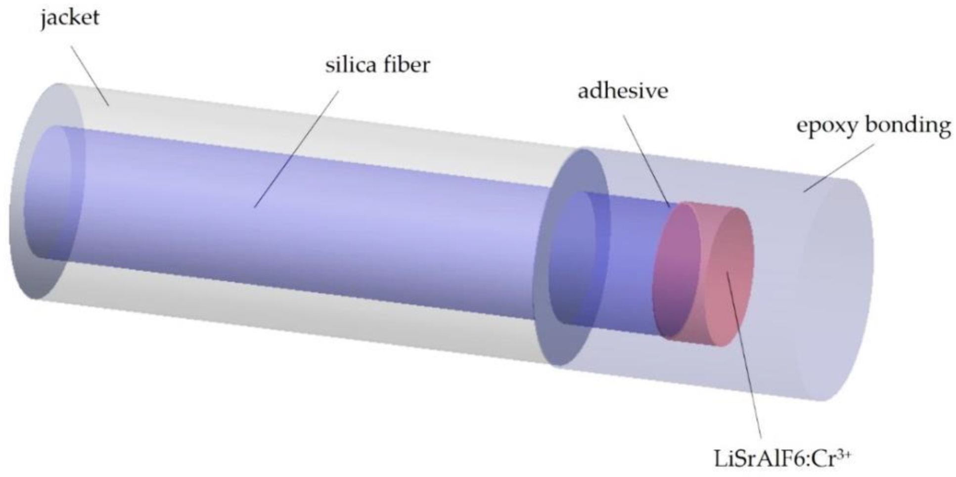
- Seat, H.C.; Sharp, J.H.; Zhang, Z.Y.; Grattan, K.T.V. Single-crystal ruby fiber temperature sensor. Sens. Actuators A Phys. 2002, 101, 24–29. [Google Scholar] [CrossRef]
- Zhang, Z.; Grattan, K.; Palmer, A. Cr: LiSAF fluorescence-lifetime-based fiber optic thermometer and its applications in clinical RF heat treatment. In Advances in Fluorescence Sensing Technology: Lifetime-Based Sensing. SPIE 1885; Summers, R., Summan, R., Hughes, S., Eds.; International Society for Optics and Photonics: Los Angeles, CA, USA, 18 May 1993; p. 300. [Google Scholar]
- Luma Sense Biomedical Lab Kit—m3300 Product Datasheet. LumaSense Technologies. Available online: http://www.lumasenseinc.com/uploads/Products/Fiber_Optic_Temperature_Sensors/pdf/Datasheets/OEM_Modules/m3300-OEM_datasheet.pdf (accessed on 30 September 2011).
- Nakagawa, H.; Yamanashi, W.S.; Pitha, J.V.; Arruda, M.; Wang, X.; Ohtomo, K.; Beckman, K.J.; McClelland, J.H.; Lazzara, R.; Jackman, W.M. Comparison of in vivo tissue temperature profile and lesion geometry for radiofrequency ablation with a saline-irrigated electrode versus temperature control in a canine thigh muscle preparation. Circulation 1995, 91, 2264–2273. [Google Scholar] [CrossRef]
- Chen, L.; Wansapura, J.P.; Heit, G.; Butts, K. Study of laser ablation in the in vivo rabbit brain with MR thermometry. J. Magn. Reson. Imaging 2002, 16, 147–152. [Google Scholar] [CrossRef]
- Sun, M.H.; Wickersheim, K.A.; Kim, J.H. Fiber optic temperature sensors in the medical setting. In Proceedings of the SPIE 1067, Conference on Optical Fibers in Medicine: Optical Fibers in Medicine IV. SPIE, Los Angeles, CA, USA, 15 June 1989; pp. 15–21. [Google Scholar]
- Neoptix. T1™ Fiber Optic Temperature Sensor: Product Datasheet. Available online: http://www.neoptix.com/literature/v1002_Datasheet_t1.pdf (accessed on 30 September 2011).
- Thurber, K.R.; Tycko, R. Biomolecular solid state NMR with magic-angle spinning at 25 K. J. Magn. Reson. 2008, 195, 179–186. [Google Scholar] [CrossRef]
- Wonneberger, U.; Schnackenburg, B.; Wlodarczyk, W.; Walter, T.; Streitparth, F.; Rump, J.; Teichgräber, U.K.M. Intradiscal temperature monitoring using double gradient-echo pulse sequences at 1.0 T. J. Magn. Reson. Imaging 2010, 31, 1499–1503. [Google Scholar] [CrossRef]
- Streitparth, F.; Knobloch, G.; Balmert, D.; Chopra, S.; Rump, J.; Wonneberger, U.; Philipp, C.; Hamm, B.; Teichgräber, U. Laser-induced thermotherapy (LITT): Evaluation of a miniaturised applicator and implementation in a 1.0-T high-field open MRI applying a porcine liver model. Eur. Radiol. 2010, 20, 2671–2678. [Google Scholar] [CrossRef]
- Veronesi, P.; Leonelli, C.; Moscato, U.; Cappi, A.; Figurelli, O. Non-incineration microwave assisted sterilization of medical waste. J. Microw. Power Electromagn. Energy 2005, 40, 211–218. [Google Scholar] [CrossRef] [PubMed]
- Saaski, E.W.; Hartl, J.C.; Mitchell, G.L.; Wolthuis, R.A.; Afroniowitz, M.A. A family of fiber optic sensors using cavity resonator microshifts. In Proceedings of the 4th International Conference Optical Fiber Sensors, Tokyo, Japan, 7–9 October 1986; Optical Society of America: Washington, DC, USA, 1986; pp. 11–14. [Google Scholar]
- Rao, Y.J.; Jackson, D.A. A prototype fibre-optic-based Fizeau medical pressure and temperature sensor system using coherence reading. Meas. Sci. Technol. 1994, 5, 741–746. [Google Scholar] [CrossRef]
- Rao, Y.J. In-fibre Bragg grating sensors. Meas. Sci. Technol. 1997, 8, 355–375. [Google Scholar] [CrossRef]
- Rao, Y.J.; Webb, D.J.; Jackson, D.A.; Zhang, L.; Bennion, I. Optical in-fiber Bragg grating sensor systems for medical applications. J. Biomed. Opt. 1998, 3, 38–44. [Google Scholar] [CrossRef] [PubMed]
- Webb, D.J.; Hathaway, M.W.; Jackson, D.A.; Jones, S.; Zhang, L.; Bennion, I. First in-vivo trials of a fiber Bragg grating based temperature profiling system. J. Biomed. Opt. 2000, 5, 45–50. [Google Scholar] [CrossRef]
- Smith, E.J.; Patterson, B.A.; Webster, R.J.; Krug, P.A.; Jones, S.K.; Sampson, D.D. Engineering a portable quasi-distributed fibre-Bragg-grating temperature sensing system for clinical hyperthermia. In Proceedings of the 15th Optical Fiber Sensors Conference Technical Digest, Portland, OR, USA, 10 May 2002; pp. 269–272. [Google Scholar]
- Saxena, I.F.; Hui, K.; Astrahan, M. Polymer coated fiber Bragg grating thermometry for microwave hyperthermia. Med. Phys. J. 2010, 37, 4615–4619. [Google Scholar] [CrossRef]
- Samset, E.; Mala, T.; Ellingsen, R.; Gladhaug, I.; Soreide, O.; Fosse, E. Temperature measurement in soft tissue using a distributed fibre Bragg-grating sensor system. Minim. Invasive Ther. Allied Technol. 2001, 10, 89–93. [Google Scholar] [CrossRef]
- Gowardhan, B.; Thomas, B.; Asterling, S.; Sheikh, N.; Greene, D. Cryosurgery for prostate cancer: Experience with third-generation cryosurgery and novel developments in the field. Eur. Urol. Suppl. 2007, 6, 516–520. [Google Scholar] [CrossRef]
- Gowardhan, B.; Greene, D. Cryotherapy for the prostate: An in vitro and clinical study of two new developments. Advanced cryoneedles and a temperature monitoring system. BJU Int. 2007, 100, 295–302. [Google Scholar] [CrossRef]
- Martin, M.; Hussain, N.; Shoureshi, R. Fiber Bragg sensor for smart bed sheet. In Proceedings of the SPIE 5907, Optics & Photonics: Photonic Devices and Algorithms for Computing VII, San Diego, CA, USA, 15 September 2005; pp. 590706–590708. [Google Scholar]
- Ramos, A.; Abe, I.; Schiller, M.W.; Lopes, P.; Nogueira, R.; Pinto, J.L.; Simões, J.A. On the use of fiber Bragg sensors to assess temperature and thermal induce strain profiles in cemented hip mantles. J. Biomech. 2006, 39, S514. [Google Scholar] [CrossRef]
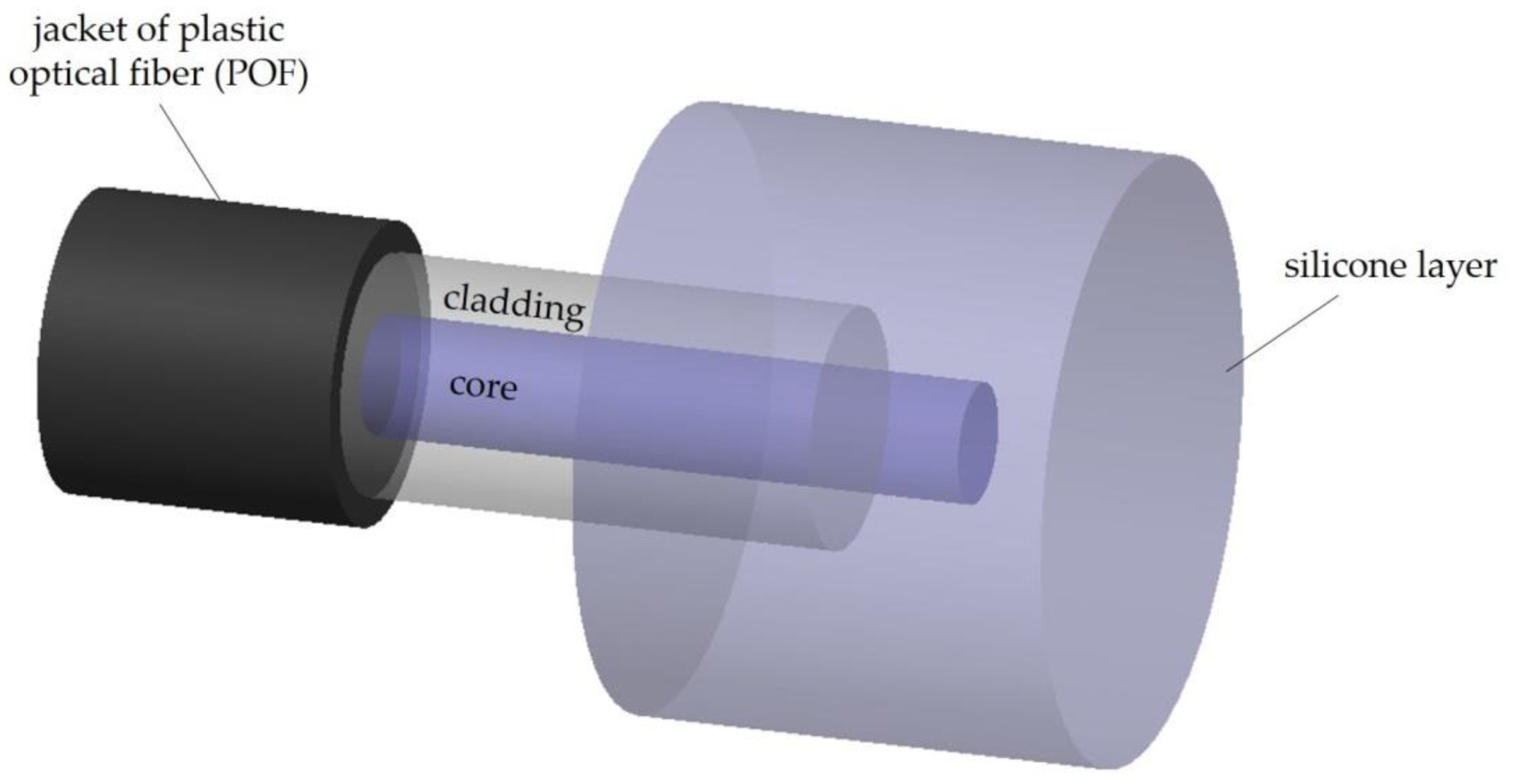
- Cennamo, N.; Monica, A.D.; Zeni, L. An optical temperature sensor based on silicone and Palstic Optical Fiber for biomedical applications. In Proceedings of the 2017 IEEE International Instrumentation and Measurement Technology Conference, Turin, Italy, 22–25 May 2017. [Google Scholar]
- Stavem, K.; Saxholm, H.; Smith-Erichsen, N. Accuracy of infrared ear thermometry in adult patients. Intensive Care Med. 1997, 23, 100–105. [Google Scholar] [CrossRef]
- Teunissen, L.P.J.; Haan, A.; Koning, J.J.; Clairbois, H.E.; Daanen, H.A.M. Limitations of temperature measurement in the aural canal with an ear mould integrated sensor. Physiol. Meas. 2011, 32, 1403–1416. [Google Scholar] [CrossRef] [PubMed]
- Mignani, A.G.; Baldini, F. Biomedical sensors using optical fibres. Rep. Prog. Phys. 1996, 59, 1–28. [Google Scholar] [CrossRef]
- Schena, E.; Tosi, D.; Sacacomandi, P.; Lewis, E.; Kim, T. Fiber optic sensors for temperature monitoring during thermal treatments: An overview. Sensors 2016, 16, 1144. [Google Scholar] [CrossRef]
- Lewis, E.; Staruch, M.A.; Chopra, R. Thermometry and ablation monitoring with ultrasound. Int. J. Hyperth. 2015, 31, 163–181. [Google Scholar] [CrossRef]
- Wu, J.L.; Wang, Y.T. A fluorescence optic-fiber temperature sensor using phase-locked detection with pulse modulation single reference. J. Phys. Conf. Ser. 2006, 48, 101. [Google Scholar] [CrossRef]
- Wook, Y.J.; Jang, K.W.; Seo, J.K.; Heo, J.Y.; Moon, J.S.; Park, J.Y.; Lee, B.S. Development of respiration sensors using plastic optical fiber for respiratory monitoring inside MRI System. J. Opt. Soc. Korea 2010, 14, 235–239. [Google Scholar]
- Tosi, D.; Macchi, E.G.; Braschi, G.; Gallati, M.; Cigada, A.; Poeggel, S.; Leen, G.; Lewis, E. Monitoring of radiofrequency thermal ablation in liver tissue through fibre Bragg grating sensors array. Electron. Lett. 2014, 50, 981–983. [Google Scholar] [CrossRef]
- Macchi, E.G.; Tosi, D.; Braschi, G.; Gallati, M.; Cigada, A.; Busca, G.; Lewis, E. Optical fiber sensors-based temperature distribution measurement in ex vivo radiofrequency ablation with submillimeter resolution. J. Biomed. Opt. 2014, 19, 117004. [Google Scholar] [CrossRef]
- Ding, Y.; Chen, N.; Chen, Z. Dynamic temperature monitoring and control with fully distributed fiber Bragg grating sensor. In Proceedings of the Photonics Asia, Optics in Health Care and Biomedical Optics IV, Beijing, China, 8 November 2010; p. 784509. [Google Scholar]
- Chen, N.; Chen, S.; Zhu, H.; Liu, S.; Chen, Z.; Pang, F.; Wang, T. In vivo experiments of laser thermotherapy on liver tissue with FBG temperature distribution sensor. In Proceedings of the Photonic Microdevices/Microstructures for Sensing IV, Baltimore, MD, USA, 26–27 April 2012. [Google Scholar]
- Samset, E.; Mala, T.; Edwin, B.; Gladhaug, I.; Søreide, O.; Fosse, E. Validation of estimated 3D temperature maps during hepatic cryo surgery. J. Magn. Reson. Imaging 2001, 19, 715–721. [Google Scholar] [CrossRef]
- Zou, X.; Wu, N.; Tian, Y.; Ouyang, J.; Barringhaus, K.; Wang, X. Miniature Fabry-Perot fiber optic sensor for intravascular blood temperature measurement. IEEE Sens. J. 2013, 13, 2155–2160. [Google Scholar] [CrossRef]
- Najafi, B.; Mohseni, H.; Grewal, G.S.; Talal, T.K.; Menzies, R.A.; Armstrong, D.G. Armstrong, An optical-fiber-based smart textile (smart socks) to manage biomechanical risk factors associated with diabetic foot amputation. J. Diabetes Sci. Technol. 2017, 11, 668–677. [Google Scholar] [CrossRef] [PubMed]
- Hazenberg, C.E.V.B.; de Stegge, W.B.; Baal, S.G.V.; Moll, F.L.; Bus, S.A. Telehealth and telemedicine applications for the diabetic foot: A systematic review. Diabetes/Metab. Res. Rev. 2019, 36, e3247. [Google Scholar] [CrossRef] [PubMed]
- Fook, V.F.S.; Jayachandran, M.; Jiliang, E.P.; Yongwein, Z.; Jianzhong, E.H. Fiber Bragg Grating-based monitoring and alert system for care of residents in nursing in nursing homes. In Proceedings of the IEEE 4th World Forum on Internet of Things (WF-IoT), Singapore, 5–8 February 2018. [Google Scholar]
- Chandrasiri, G.A.P.; Halgamuge, M.N.; Jayasekara, C.S. A Comparative Study in the Application of IOT in Health Care: Data Security in Telemedicine, Security, Privacy and Trust in the IoT Environment; Springer: Cham, Switzerland, 2019; pp. 181–202. [Google Scholar]


| Year | Configuration | Length (µm) | Range | Sensitivity | Ref |
|---|---|---|---|---|---|
| 2015 | SMF + dual HCF | 33.84 | 20 to 60 °C | −0.4810 nm/°C | [60] |
| 2015 | Polymer capped on the end face of SMF | 35.1 | 40 to 90 °C | 0.249 nm/°C | [61] |
| 2015 | Rectangular air bubble between SMFs | ~61 | 25 to 100 °C | 2.0 pm/°C | [62] |
| 2015 | SMF + silicon pillar | 200 | 20 to 100 °C | 84.6 pm/°C | [63] |
| 2015 | MMF + Pyrex glass + silicon diaphragm | ~32 | −50 to 100 °C | 6.07 nm/°C | [64] |
| 2016 | Air cavities with capillary fiber between 2 SMFs | ~25-200 | 50 to 400 °C | 0.8 pm/°C | [65] |
| 2016 | SMF + hollow-core photonic crystal fiber (PCF) | 75 | 17 to 900 °C | 0.94 pm/°C | [66] |
| 2016 | SMF + PCF | 94 | 20 to 90 °C | 9.17 pm/°C | [67] |
| 2017 | Etched MMF filled with UV adhesive | 37.7 | 55 to 85°C | 213 pm/°C | [68] |
| 2018 | SMF + Hollow core tube + SMF | ~100 | 50–450 °C | 0.902 pm/°C | [69] |
| 2018 | Fiber core near the end of a standard SMF | 60 | 500 to 1000 °C | 18.6 pm/°C | [70] |
| 2018 | SMF +capillary + nafion film | 200 | −30 to 85 °C | 2.71 nm/°C | [71] |
| 2019 | SMF + HCF + HCF | 210 | 30 to 200 °C | 9.22 pm/°C | [72] |
| 2019 | SMF + HCF + grapefruit PCF | 1229 | 25 to 70 °C | 10.64 pm/°C | [73] |
| 2019 | SMF + HCF + long period fiber grating +SMF | 474.4 | 31.5 to 82.4°C | 135.19 pm/°C | [74] |
| 2020 | SMF + FBG + FBG + SMF | ------ | 25 to 45 °C | 307.6 pm/°C | [75] |
| 2020 | Parallel FPI | 26 61 | 20 to 80 °C | 0.74 pm/°C 1.37 pm/°C | [76] |
| 2020 | SMF + polarization maintaining PCF | 150 | 300 to 800 °C | −92 pm/°C | [77] |
| Year | Configuration | Length (mm) | Range | Sensitivity | Ref |
|---|---|---|---|---|---|
| 2015 | SMF + no core fiber (NCF) (diameter of 96 µm) + SMF | 34.43 | −30 to 100 °C | 38.7 pm/°C | [92] |
| 2015 | SMF + offset SMF + SMF | 46 | 30 to 270 °C | 0.0449 nm/°C | [93] |
| 2015 | SMF + NCF + SMF | 40 | 10 to 100 °C | 5.15 nm/°C | [94] |
| 2017 | SMF + MMF (core of 105 µm) + SMF | 44 | 15 to 75 °C | 29.33 pm/°C | [95] |
| 2017 | SMF + polymer optical fiber (POF) + SMF | 10 | 25 to 105 °C | 102.2 pm/°C | [96] |
| 2017 | SMF + MMF + MMF + SMF | 100 | 30 to 90 °C | 6.8 pm/°C | [97] |
| 2018 | SMF + NCF (with alcohol solution within a silica capillary tube) + SMF | 40 | 20 to 45 °C | 0.49 dB/°C | [98] |
| 2018 | SMF + NCF | 43.9 | 100 to 700 °C | 6.8 pm/°C | [79] |
| 2018 | SMF + NCF | 30 | 10 to 70 °C | 13.6 pm/°C | [99] |
| 2019 | SMF + MMF + SMF | 70 | 31.4 to 80.2 °C | 21 pm/°C | [100] |
| 2019 | SMF + MMF + NCF + MMF + SMF | 1 | 20 to 100 °C | 33 pm/°C | [101] |
| 2019 | SMF + MMF + polarization maintaining fiber + MMF + SMF | 32 | 20 to 40 °C | 0.188 nm/°C | [102] |
| 2020 | SMF + NCF (with a gold film) + SMF | 12 | 20 to 80 °C | 37.9 pm/°C | [103] |
| 2020 | SMF + NCF (with coating) + SMF | 15 | −5 to 45 °C | −4.677 nm/°C | [104] |
| 2020 | SMF + hollow-core capillary waveguide + SMF | 29.5 | 25 to 75 °C | −0.49 nm/°C | [105] |
© 2020 by the authors. Licensee MDPI, Basel, Switzerland. This article is an open access article distributed under the terms and conditions of the Creative Commons Attribution (CC BY) license (http://creativecommons.org/licenses/by/4.0/).
Share and Cite
Roriz, P.; Silva, S.; Frazão, O.; Novais, S. Optical Fiber Temperature Sensors and Their Biomedical Applications. Sensors 2020, 20, 2113. https://doi.org/10.3390/s20072113
Roriz P, Silva S, Frazão O, Novais S. Optical Fiber Temperature Sensors and Their Biomedical Applications. Sensors. 2020; 20(7):2113. https://doi.org/10.3390/s20072113
Chicago/Turabian StyleRoriz, Paulo, Susana Silva, Orlando Frazão, and Susana Novais. 2020. "Optical Fiber Temperature Sensors and Their Biomedical Applications" Sensors 20, no. 7: 2113. https://doi.org/10.3390/s20072113
APA StyleRoriz, P., Silva, S., Frazão, O., & Novais, S. (2020). Optical Fiber Temperature Sensors and Their Biomedical Applications. Sensors, 20(7), 2113. https://doi.org/10.3390/s20072113