A Wristwatch-Based Wireless Sensor Platform for IoT Health Monitoring Applications

 , , , ,
Abstract
:1. Introduction
2. Comparison of Wireless Performance in the 868 MHz and 2.45 GHz ISM Bands
2.1. Free Space Path Loss
2.2. Radio Frequency (RF) Attenuation in Indoor Environment
2.3. Co-Existence Issues
2.4. Power Consumption
2.5. Wireless Communication Range
3. System Design
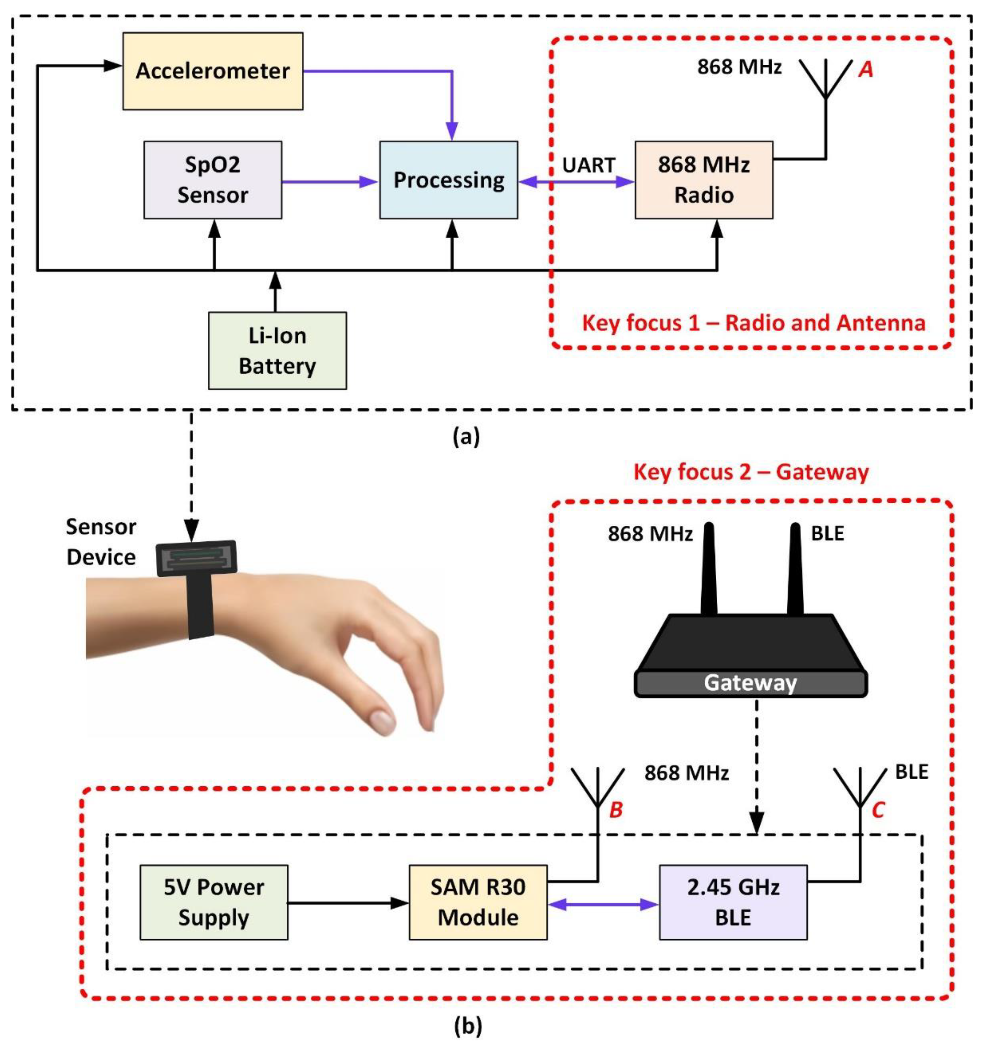
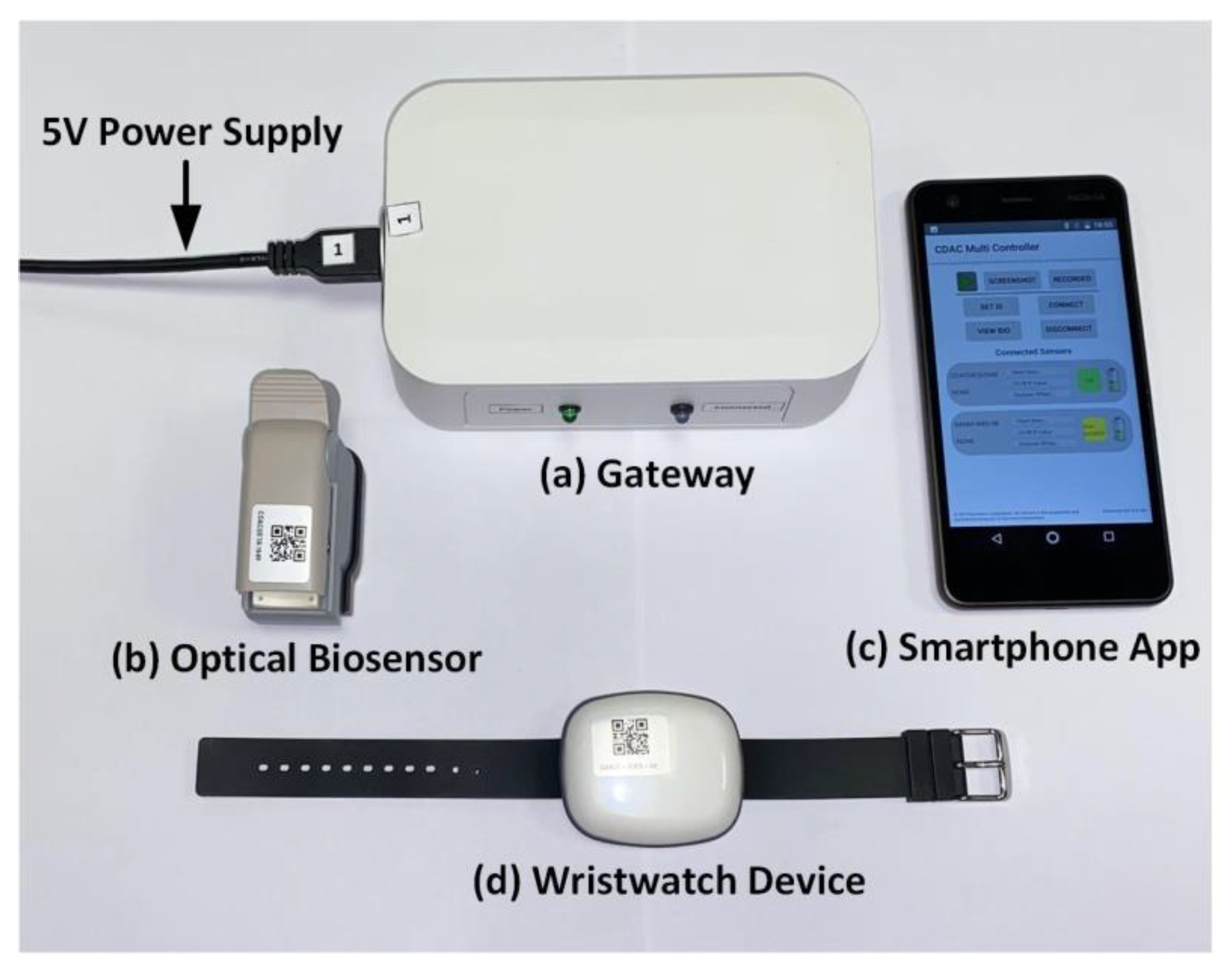
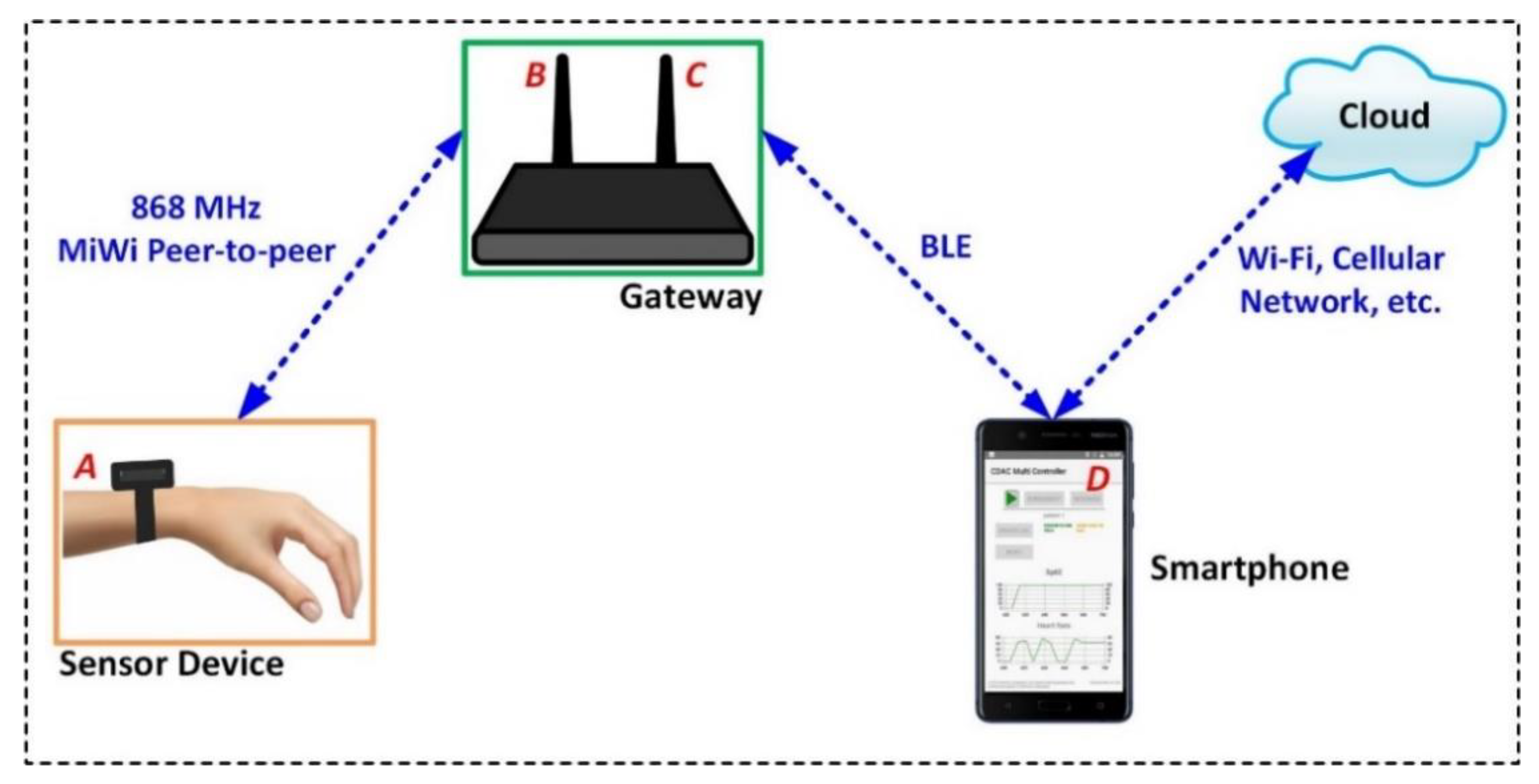
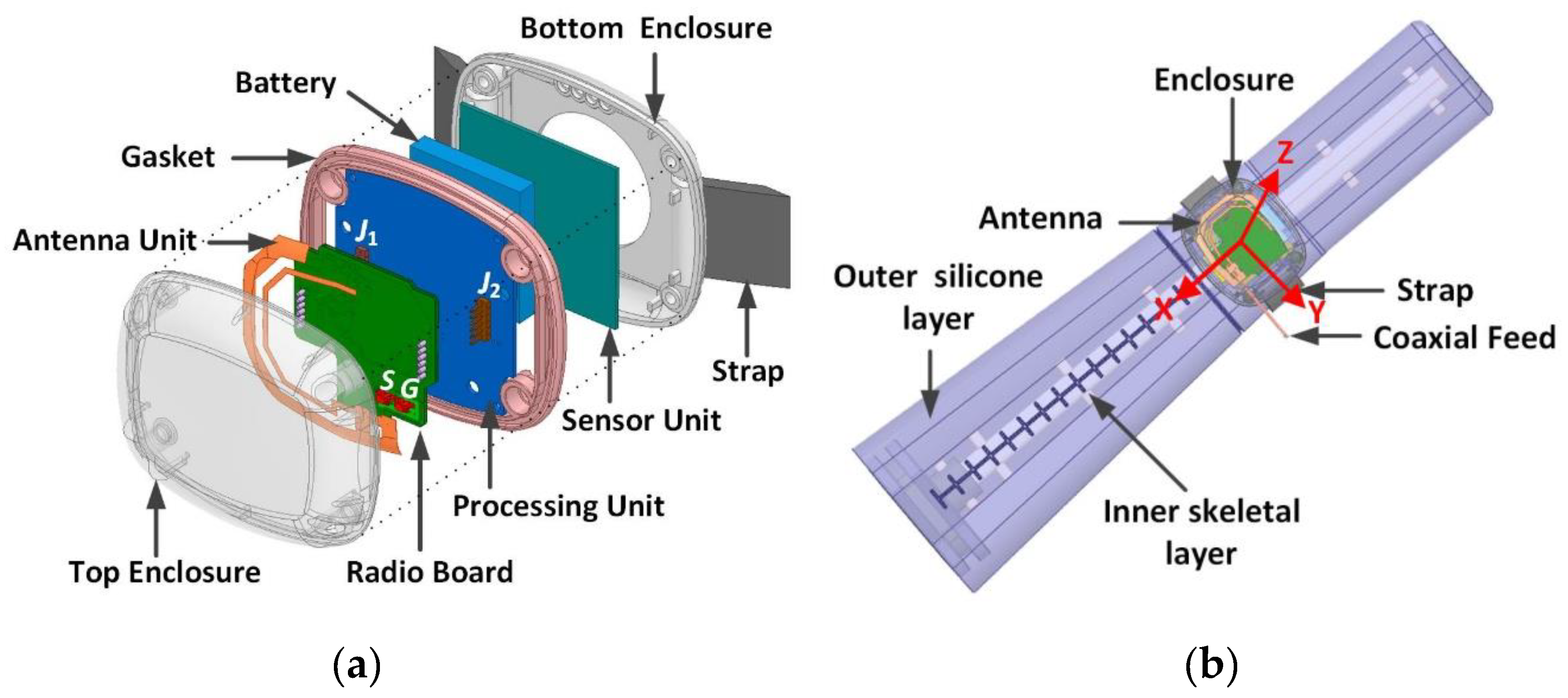
3.1. System Hardware Architecture
3.2. System Software Design
3.2.1. Wireless Network Protocol
- Bidirectional communication;
- Minimum throughput that allows the reliable transfer of sensor data and control commands;
- Handle a burst of data of 500 bytes;
- Determine sleep/active cycles of the wristwatch to enable power saving.
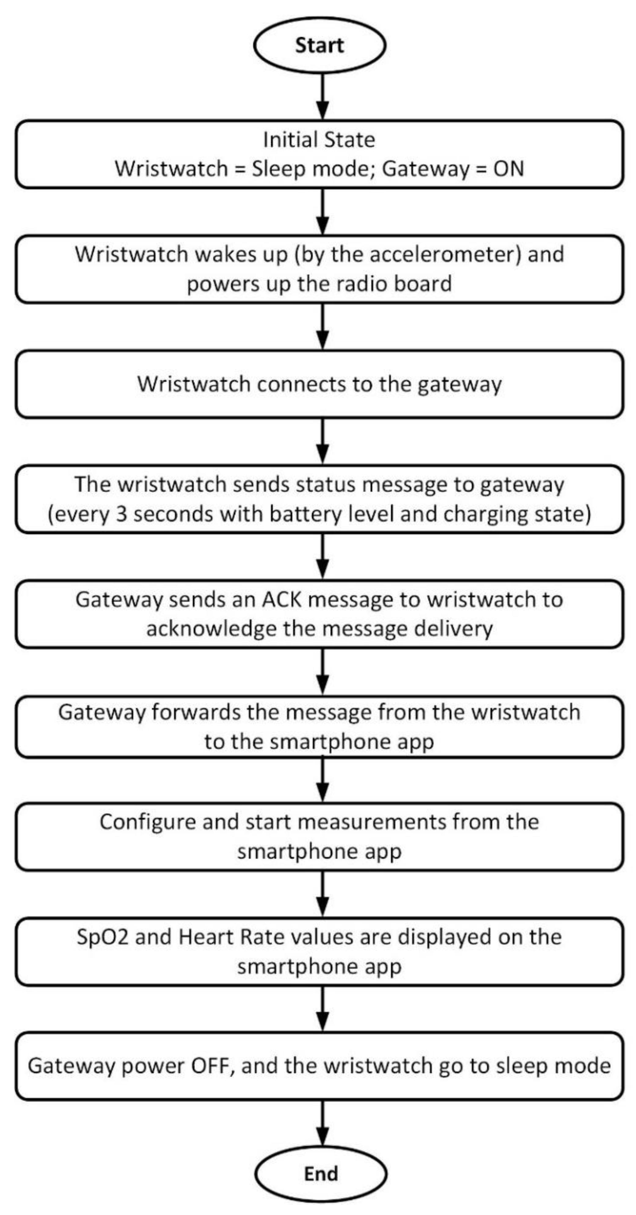
3.2.2. System Workflow
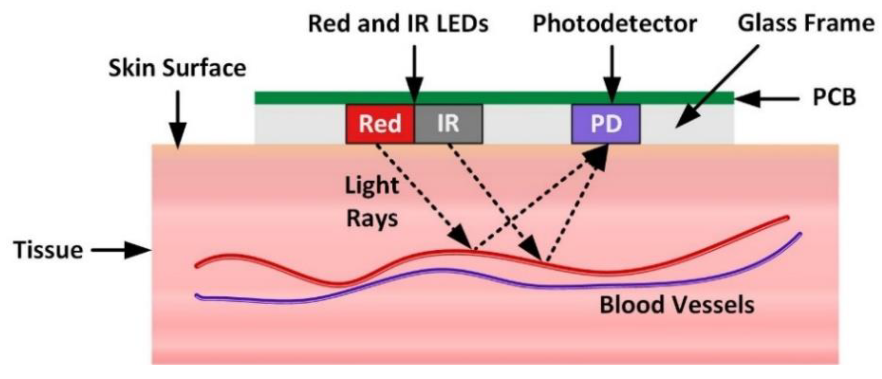
3.3. Working Principle of the PPG Sensor
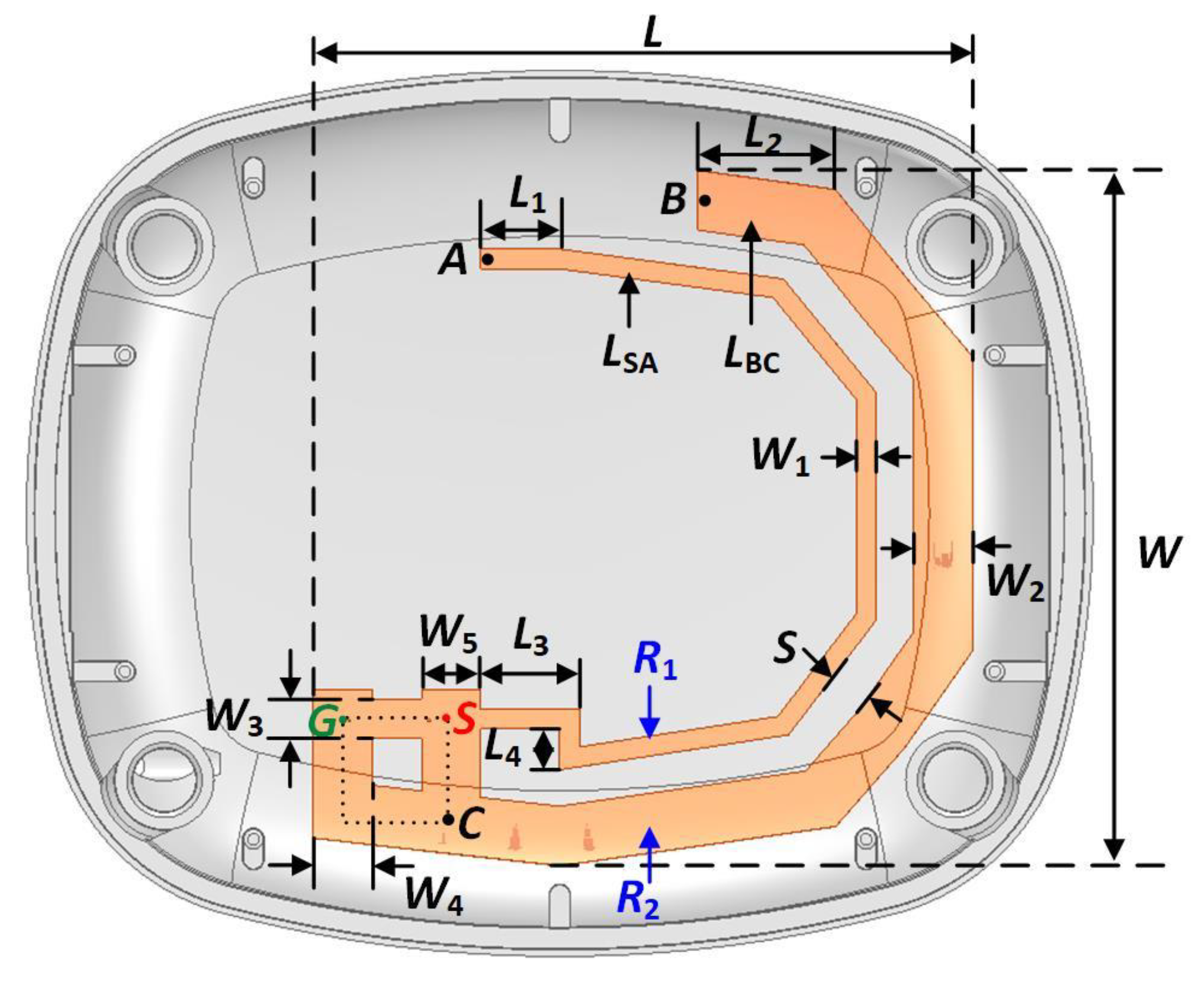
4. Antenna Design
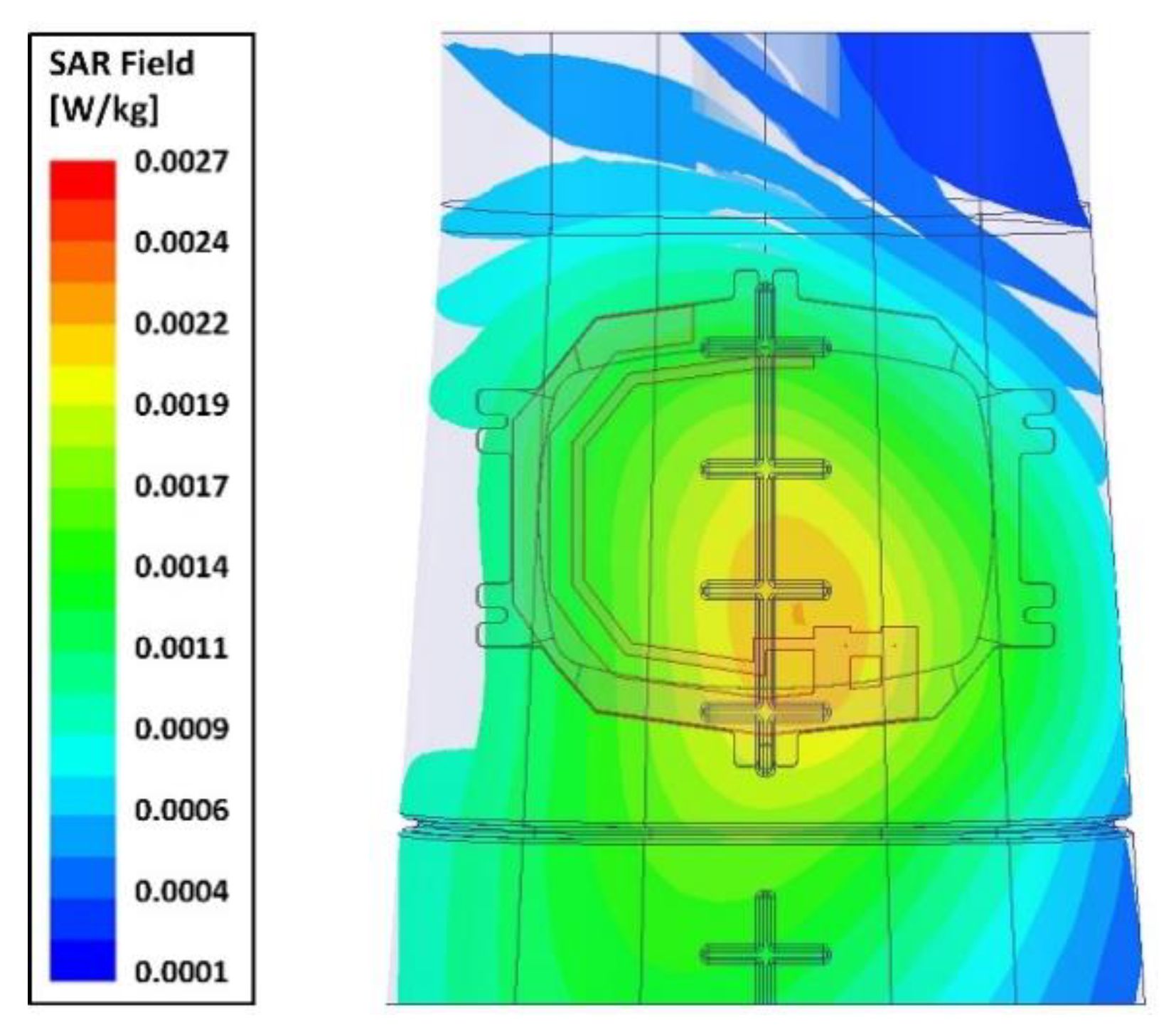
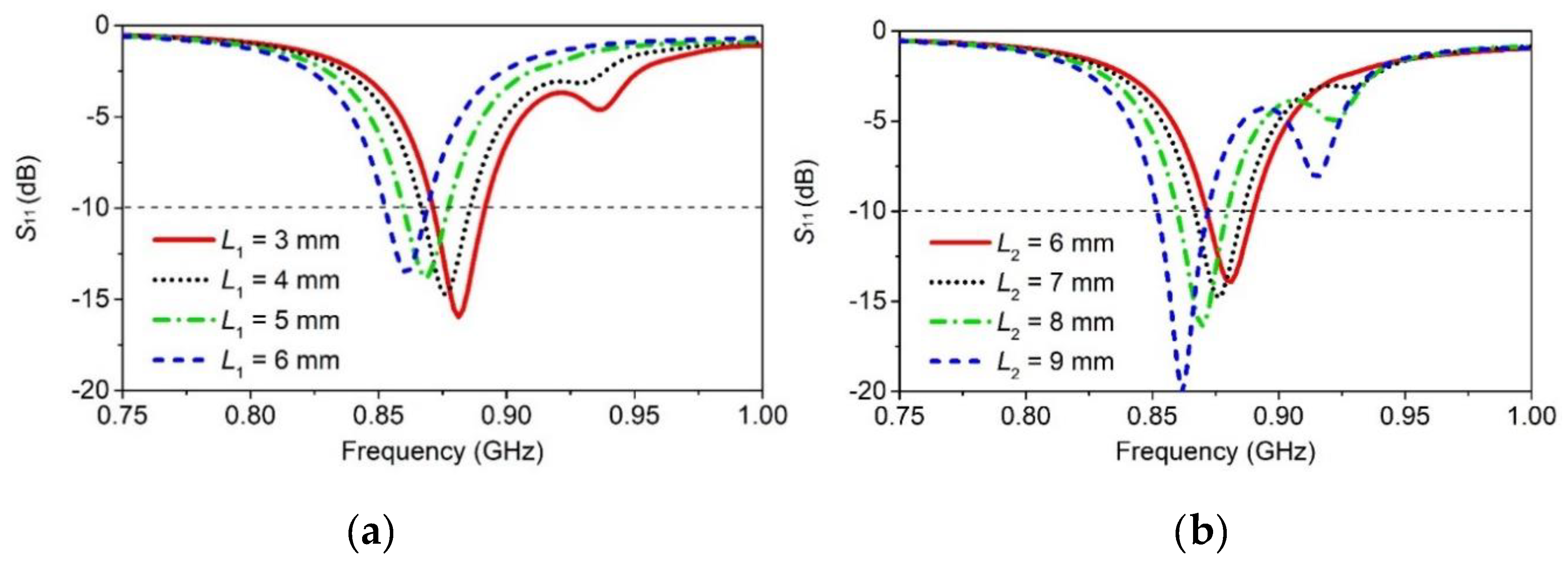
4.1. Antenna Simulations
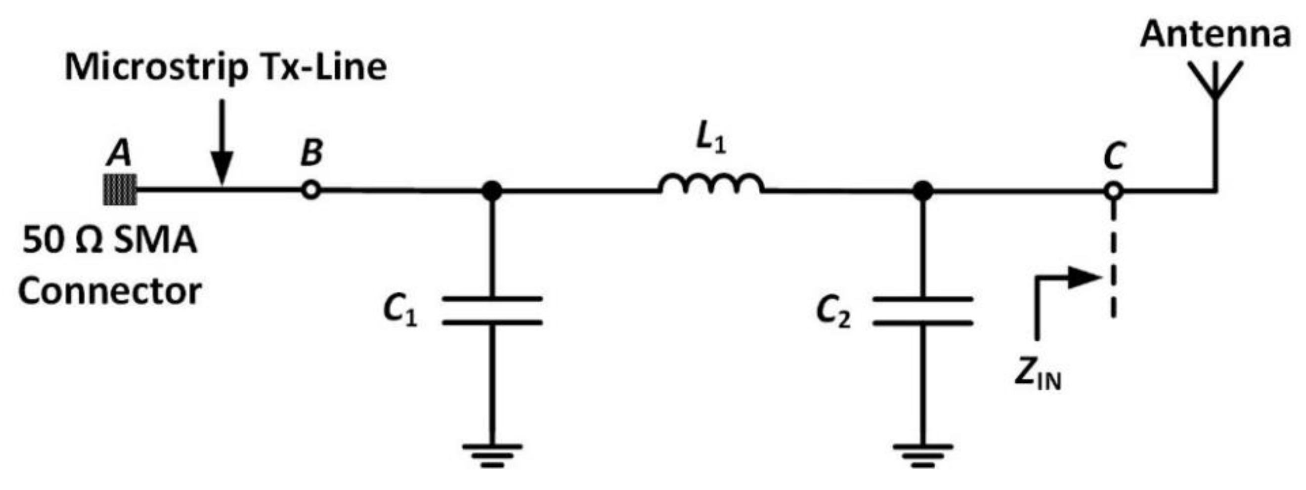
4.2. Impedance Matching and Bandwidth Enhancement
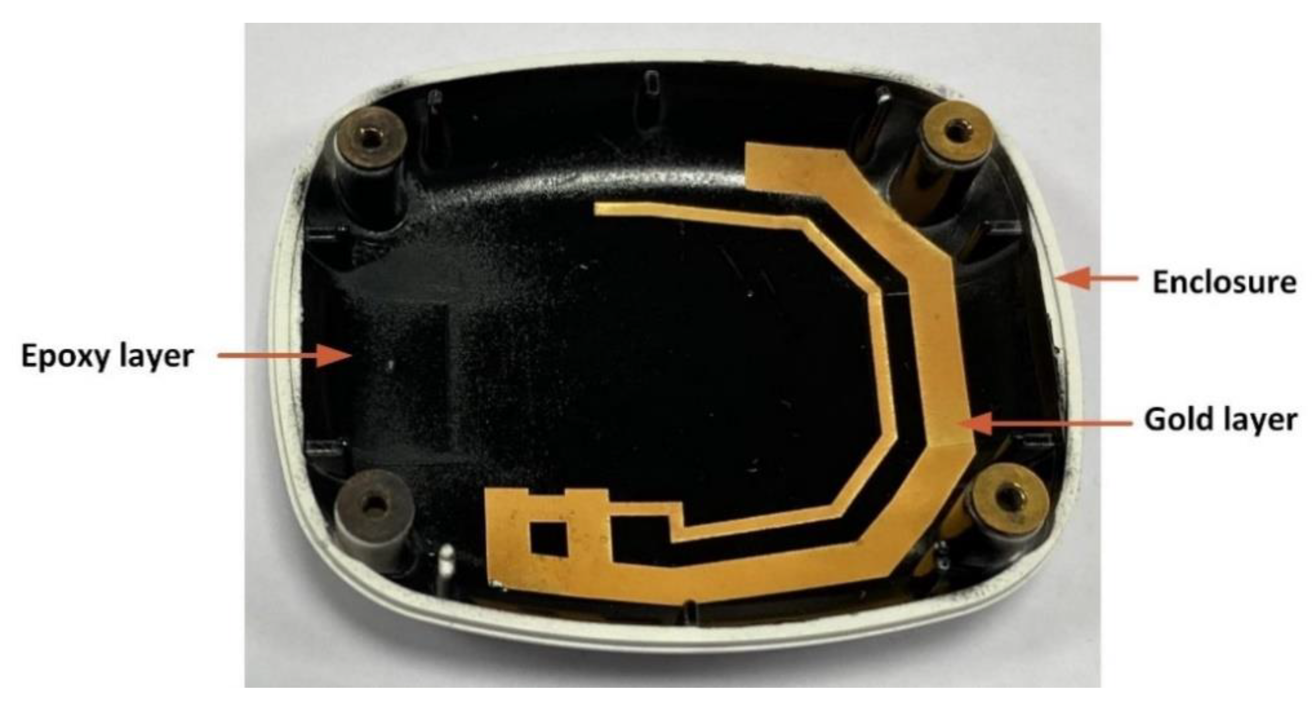
4.3. Antenna Prototype Fabrication
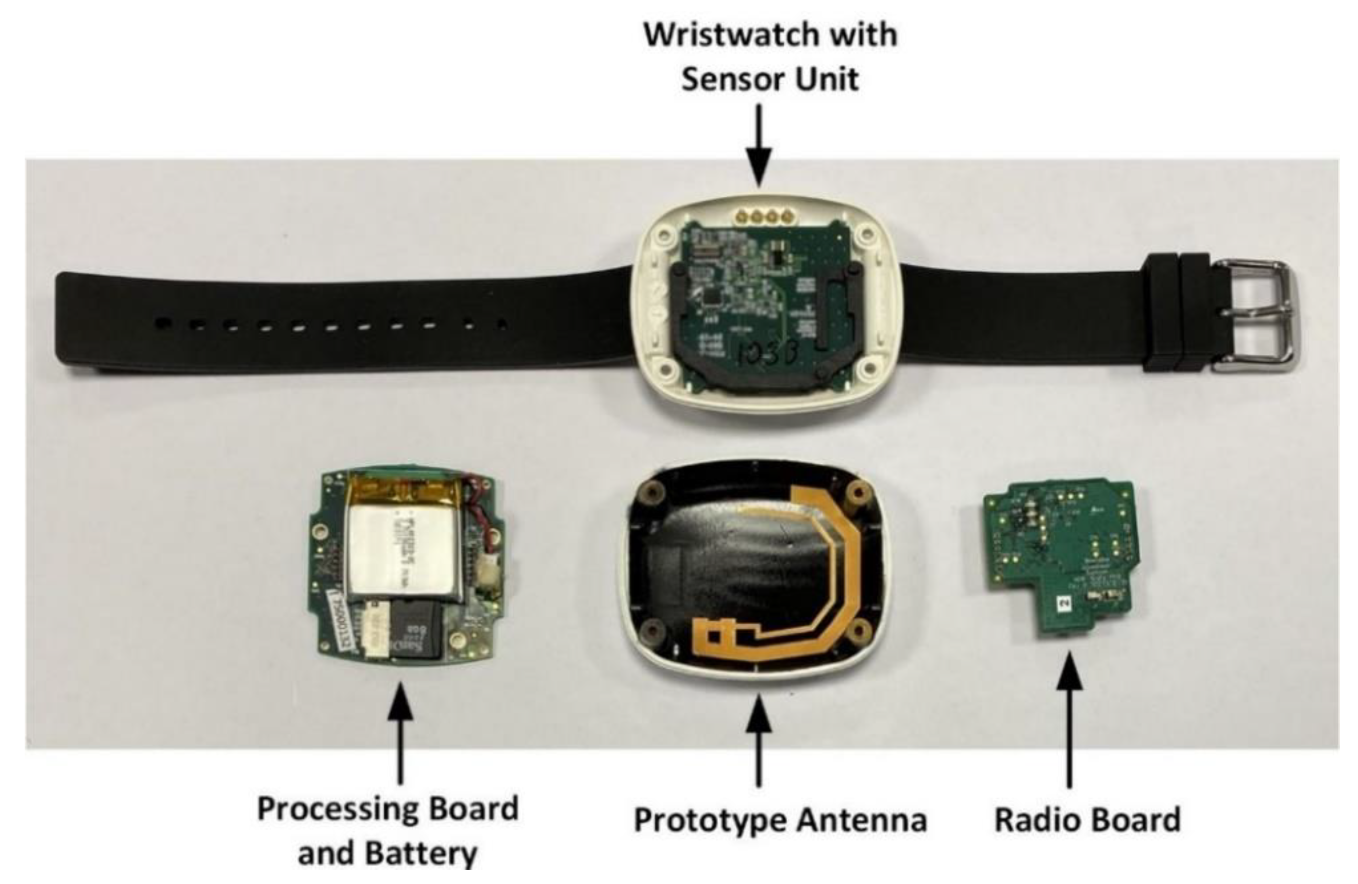
- 3D part fabrication or selection: The 3D part/object on which the metal has to be printed can be fabricated using standard 3D printers. The commercially available thermoplastic parts, such as metals, plastics, glass, FR4, can also be used. In this work, the antenna structure is printed on an ASA thermoplastic wristwatch enclosure from OKW enclosures [61];
- Part coating with ProtoPaint epoxy: The part is covered with the LPKF ProtoPaint LDS epoxy layer;
- Laser direct structuring: The LPKF laser system creates an outline of the conductive pattern of the design. In this step, the laser removes some of the epoxy material and forms a rough surface on which the copper can firmly adhere during metallization;
- Metallization: This step involves the electroless copper plating of the region exposed by laser etching. The photograph of the antenna track during the metallization process is shown in Figure 11. The metallization of the antenna track was completed in the following four steps:
- Step 1: In order to get a low resistance electrical continuity through the activated track on the plastic, copper electroless deposition of the surface was required to make it possible to electroplate it. Using an in-house developed, dimethylamine borane (DMAB)-based copper electroless deposition solution, the track was metallized with copper. The sample was immersed in the bath for 60 min at 70 °C, pH9;
- Step 2: The electroless copper deposited on the sample needed to be electroplated up with copper. A Schlotter commercial copper bright bath, ACG8, was utilized for this process. The sample was plated for 60 min, 2 A/dm2 at room temperature;
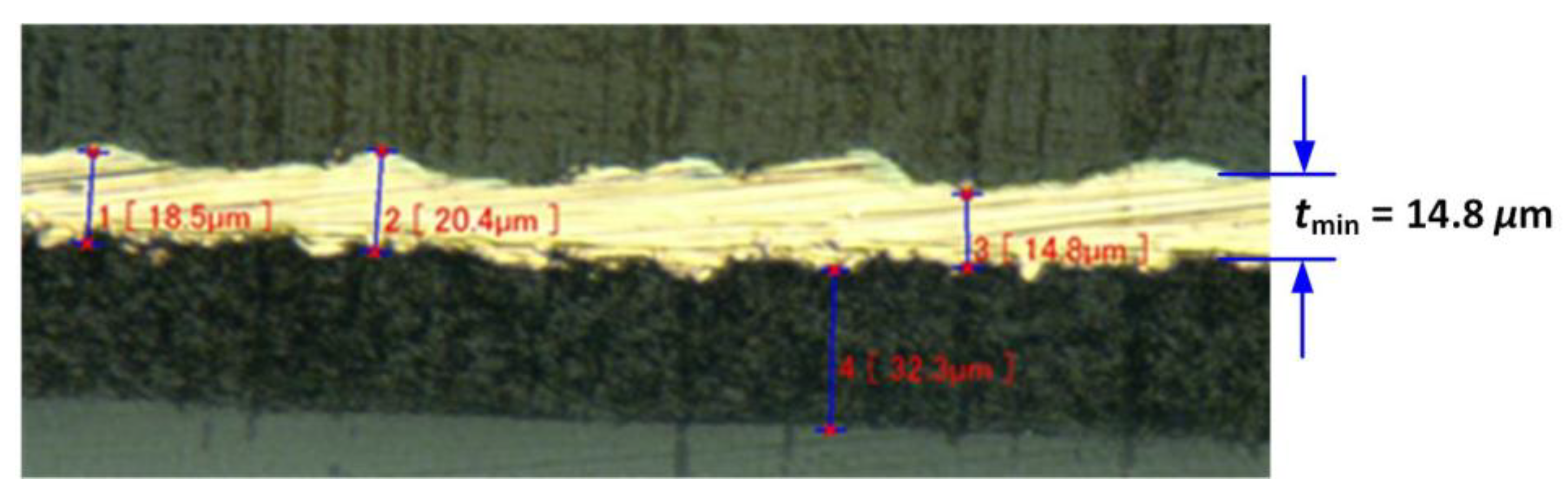
- Step 3: Utilizing an in-house developed, low stress nickel-sulphamate-based electroplating bath, the sample was plated for 10 min, 3 A/dm2, at 60 °C. The minimum thickness (tmin) of the electroplated copper is 14.8 μm, as shown;
- Step 4: To avoid oxidation of the nickel surface, a commercially available gold Ormex immersion solution by Engelhard was used to finish the surface with gold. The thickness of the gold finish is less than 0.11 μm. This process took 7 minutes at a temperature of 85 °C.
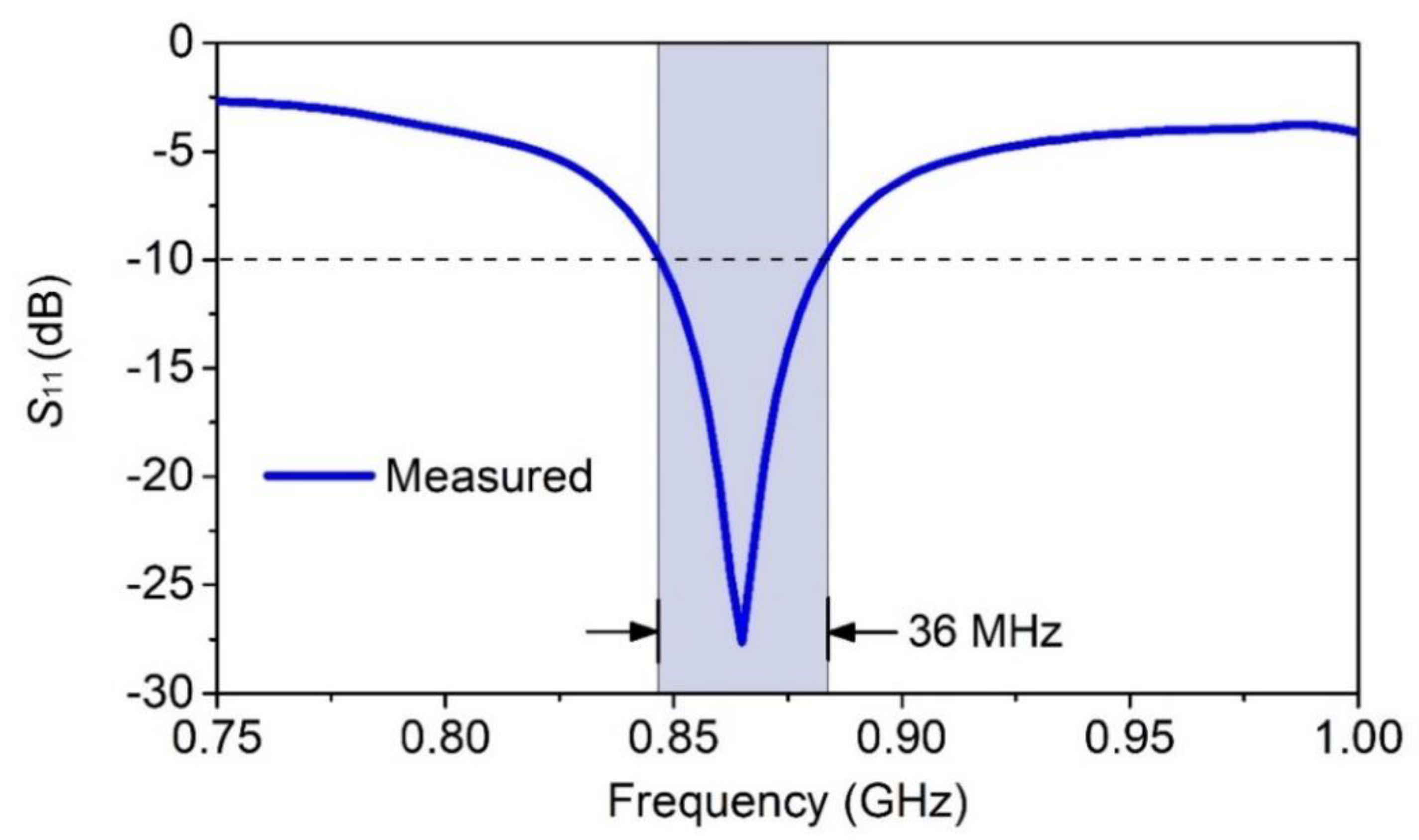
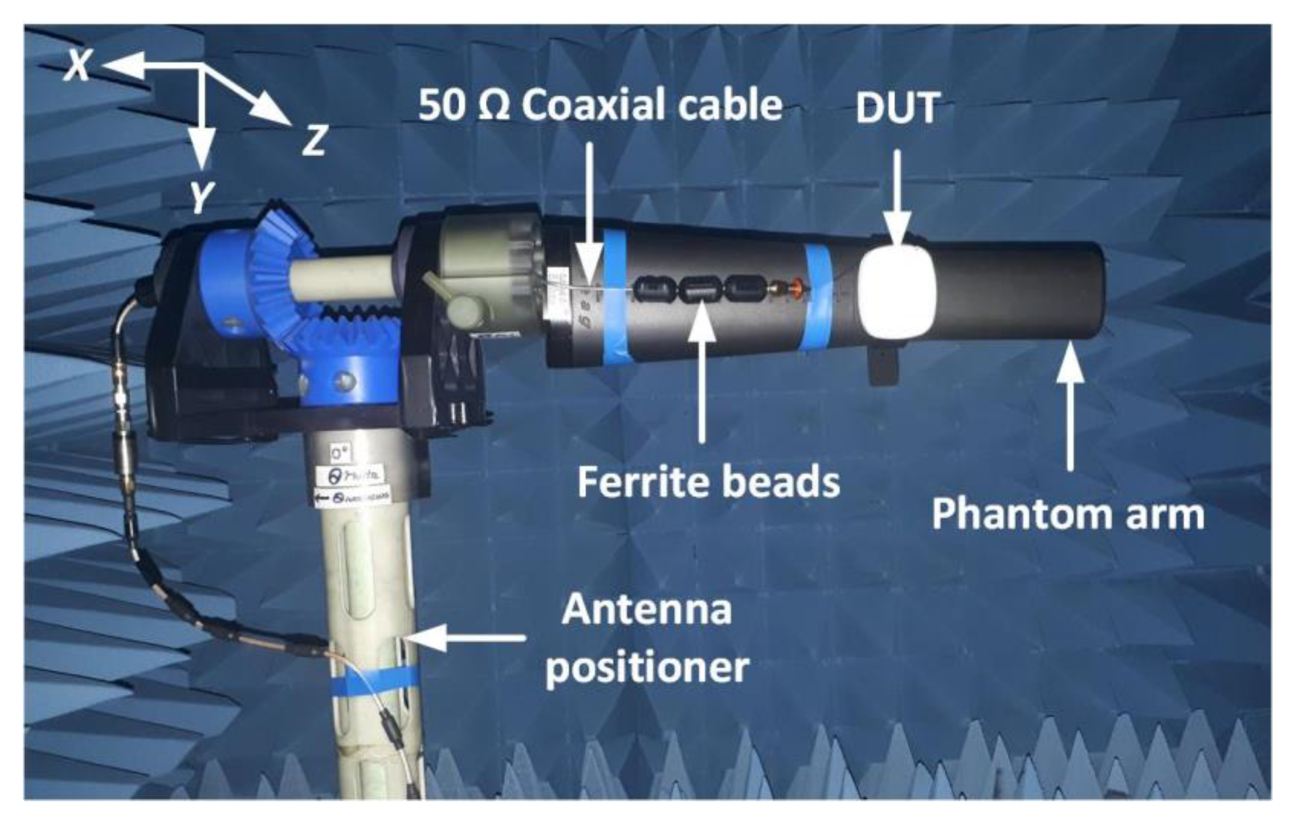
4.4. Antenna Measurements
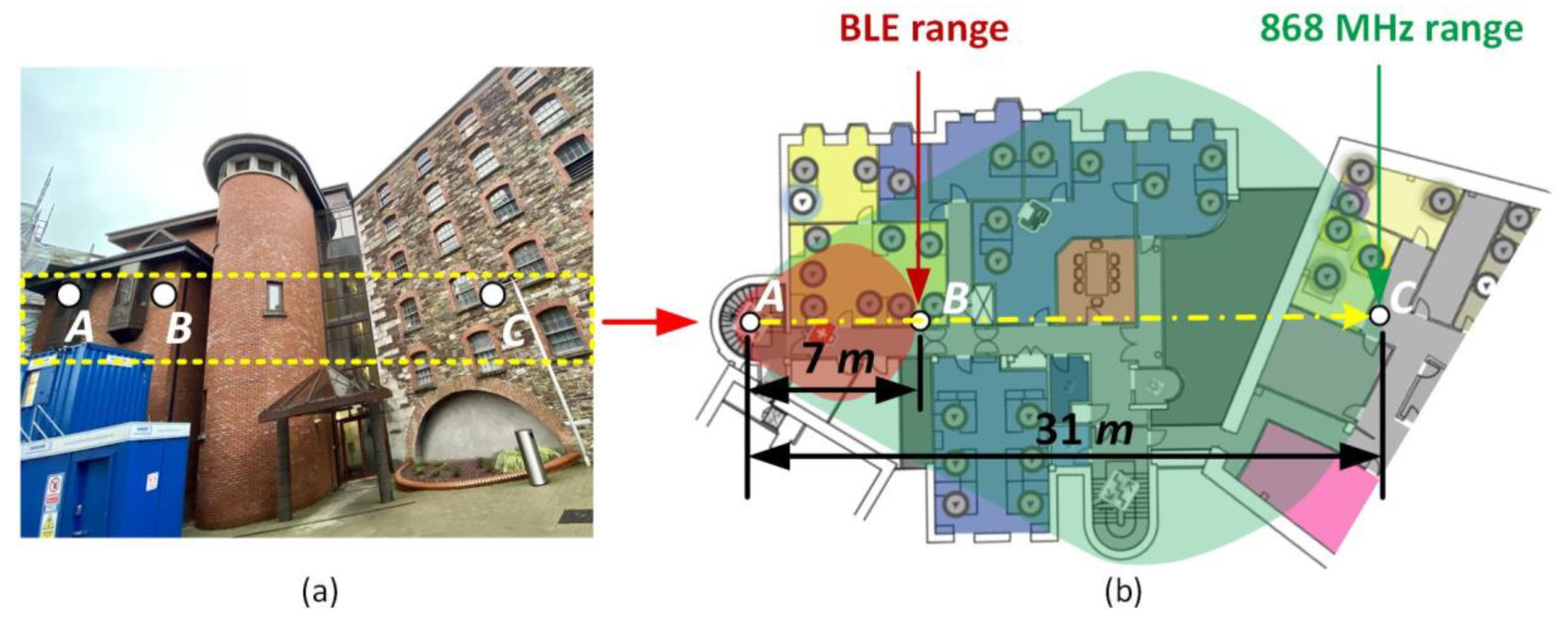
5. Communication Range Measurements of the Sensor Platform
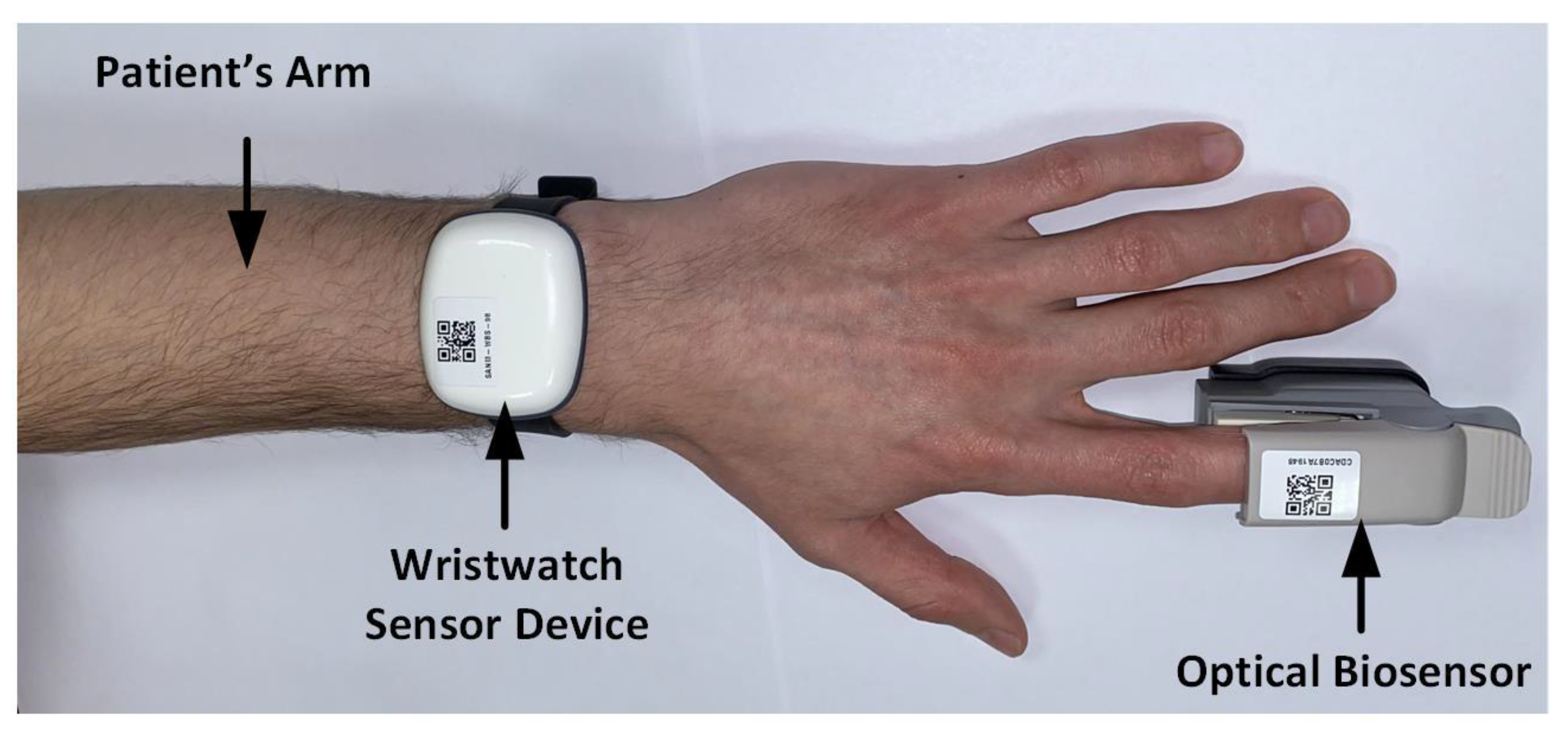
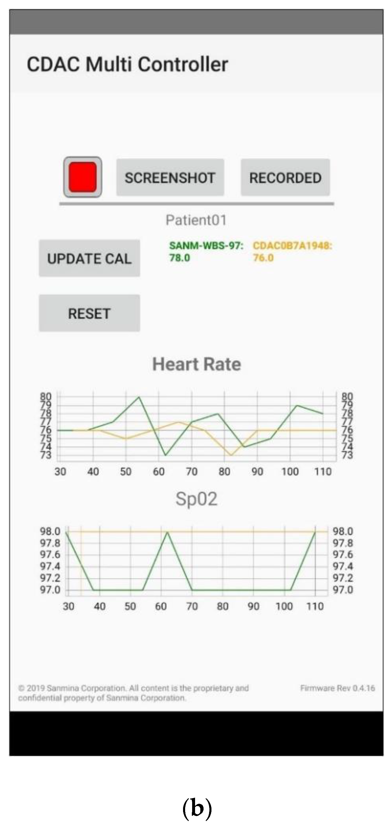
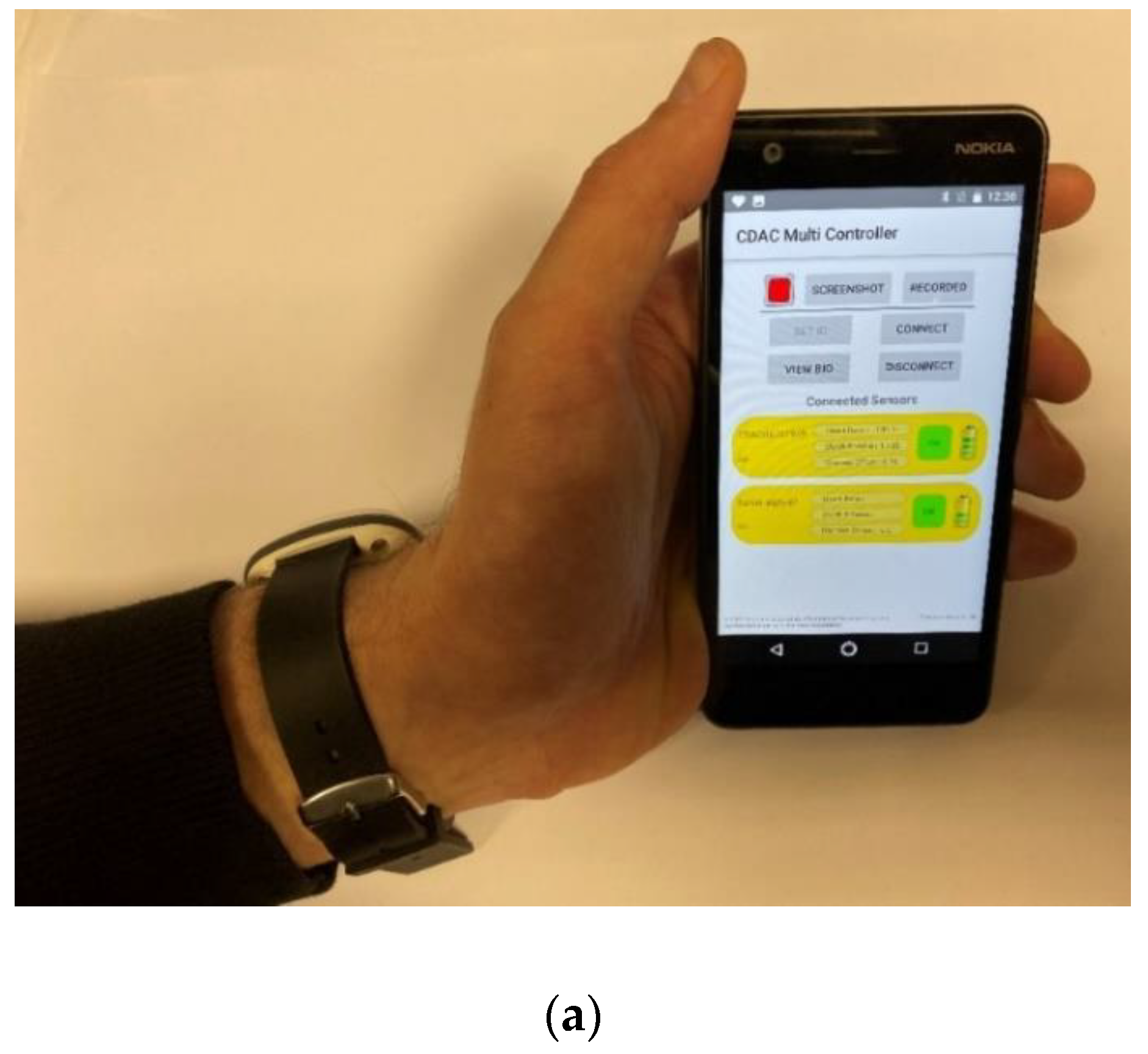
6. System Implementation and Clinical Trials
7. Conclusions
Supplementary Materials
Author Contributions
Funding
Acknowledgments
Conflicts of Interest
References
- Khan, R.; Khan, S.U.; Zaheer, R.; Khan, S. Future Internet: The Internet of Things Architecture, Possible Applications and Key Challenges. In Proceedings of the 2012 10th International Conference on Frontiers of Information Technology, Islamabad, Pakistan, 17–19 December 2012; pp. 257–260. [Google Scholar]
- Vermesan, O.; Friess, P. Internet of Things Applications: From Research and Innovation to Market Deployment; River Publishers: Aalborg, Denmark, 2014. [Google Scholar]
- Faheem, M.; Butt, R.A.; Raza, B.; Alquhayz, H.; Abbas, M.Z.; Ngadi, M.A.; Gungor, V.C. A Multiobjective, Lion Mating Optimization Inspired Routing Protocol for Wireless Body Area Sensor Network Based Healthcare Applications. Sensors 2019, 19, 5072. [Google Scholar] [CrossRef] [PubMed] [Green Version]
- Size of the Internet of Things (IoT) Market Worldwide from 2017 to 2025 (in Billion U.S. Dollars). Available online: https://www.statista.com/statistics/976313/global-iot-market-size/ (accessed on 26 November 2019).
- Di Serio, A.; Buckley, J.; Barton, J.; Newberry, R.; Rodencal, M.; Dunlop, G.; O’Flynn, B. Potential of Sub-GHz Wireless for Future IoT Wearables and Design of Compact 915 MHz Antenna. Sensors 2018, 18, 22. [Google Scholar] [CrossRef] [PubMed] [Green Version]
- End-User Spending of Wearable Devices Worldwide from 2018 to 2021, by Category (in Billion U.S. Dollars). Available online: https://www.statista.com/statistics/1065271/wearable-devices-worldwide-spending/ (accessed on 26 November 2019).
- Chatterjee, S.; Kyriacou, P.A. Monte Carlo Analysis of Optical Interactions in Reflectance and Transmittance Finger Photoplethysmography. Sensors 2019, 19, 789. [Google Scholar] [CrossRef] [PubMed] [Green Version]
- Allen, J. Photoplethysmography and its application in clinical physiological measurement. Physiol. Meas. 2007, 28, R1–R39. [Google Scholar] [CrossRef] [PubMed] [Green Version]
- Hickey, M.; Phillips, J.P.; Kyriacou, P.A. Investigation of peripheral photoplethysmographic morphology changes induced during a hand-elevation study. J. Clin. Monit. Comput. 2016, 30, 727–736. [Google Scholar] [CrossRef] [PubMed]
- Shelley, K.H. Photoplethysmography: Beyond the Calculation of Arterial Oxygen Saturation and Heart Rate. Anesth. Analg. 2007, 105, S31–S36. [Google Scholar] [CrossRef] [PubMed] [Green Version]
- Apple. Apple Smart Watch. Available online: https://www.apple.com/ie/watch/ (accessed on 30 November 2019).
- Huawei. Huawei Smartwatch. Available online: https://consumer.huawei.com/en/wearables/ (accessed on 30 November 2019).
- Fitbit. Fitbit Smart Watch. Available online: https://www.fitbit.com/ie/home (accessed on 30 November 2019).
- Fossil. Sport Smartwatches. Available online: https://www.fossil.com/en-gb/smartwatches/explore/sport/ (accessed on 3 December 2019).
- Soh, P.J.; Vandenbosch, G.A.E.; Mercuri, M.; Schreurs, D.M.M. Wearable Wireless Health Monitoring: Current Developments, Challenges, and Future Trends. IEEE Microw. Mag. 2015, 16, 55–70. [Google Scholar] [CrossRef]
- Wan, J.; Al-awlaqi, M.A.; Li, M.; O’Grady, M.; Gu, X.; Wang, J.; Cao, N. Wearable IoT enabled real-time health monitoring system. EURASIP J. Wirel. Commun. Netw. 2018, 2018, 298. [Google Scholar] [CrossRef]
- Zhu, B.; Ling, Y.; Yap, L.W.; Yang, M.; Lin, F.; Gong, S.; Wang, Y.; An, T.; Zhao, Y.; Cheng, W. Hierarchically Structured Vertical Gold Nanowire Array-Based Wearable Pressure Sensors for Wireless Health Monitoring. ACS Appl. Mater. Interfaces 2019, 11, 29014–29021. [Google Scholar] [CrossRef]
- Morgenthal, G.; Eick, J.F.; Rau, S.; Taraben, J. Wireless Sensor Networks Composed of Standard Microcomputers and Smartphones for Applications in Structural Health Monitoring. Sensors 2019, 19, 2070. [Google Scholar] [CrossRef] [Green Version]
- Manogaran, G.; Shakeel, P.M.; Fouad, H.; Nam, Y.; Baskar, S.; Chilamkurti, N.; Sundarasekar, R. Wearable IoT Smart-Log Patch: An Edge Computing-Based Bayesian Deep Learning Network System for Multi Access Physical Monitoring System. Sensors 2019, 19, 3030. [Google Scholar] [CrossRef] [PubMed] [Green Version]
- Mora, H.; Gil, D.; Terol, R.M.; Azorín, J.; Szymanski, J. An IoT-Based Computational Framework for Healthcare Monitoring in Mobile Environments. Sensors 2017, 17, 2302. [Google Scholar] [CrossRef] [PubMed] [Green Version]
- Xia, Z.; Zhu, Y.; Sun, X.; Qin, Z.; Ren, K. Towards Privacy-Preserving Content-Based Image Retrieval in Cloud Computing. IEEE Trans. Cloud Comput. 2018, 6, 276–286. [Google Scholar] [CrossRef]
- Wu, D.; Cheung, S.W. A Cavity-Backed Annular Slot Antenna with High Efficiency for Smartwatches with Metallic Housing. IEEE Trans. Antennas Propag. 2017, 65, 3756–3761. [Google Scholar] [CrossRef]
- Su, S.; Hsieh, Y. Integrated Metal-Frame Antenna for Smartwatch Wearable Device. IEEE Trans. Antennas Propag. 2015, 63, 3301–3305. [Google Scholar] [CrossRef]
- Antolín, D.; Medrano, N.; Calvo, B.; Pérez, F. A Wearable Wireless Sensor Network for Indoor Smart Environment Monitoring in Safety Applications. Sensors 2017, 17, 365. [Google Scholar] [CrossRef]
- Cavallari, R.; Martelli, F.; Rosini, R.; Buratti, C.; Verdone, R. A Survey on Wireless Body Area Networks: Technologies and Design Challenges. IEEE Commun. Surv. Tutor. 2014, 16, 1635–1657. [Google Scholar] [CrossRef]
- Karvonen, H.; Hämäläinen, M.; Iinatti, J.; Pomalaza-Ráez, C. Coexistence of wireless technologies in medical scenarios. In Proceedings of the 2017 European Conference on Networks and Communications (EuCNC), Oulu, Finland, 12–15 June 2017; pp. 1–5. [Google Scholar]
- De Poorter, E.; Hoebeke, J.; Strobbe, M.; Moerman, I.; Latré, S.; Weyn, M.; Lannoo, B.; Famaey, J. Sub-GHz LPWAN Network Coexistence, Management and Virtualization: An Overview and Open Research Challenges. Wirel. Pers. Commun. 2017, 95, 187–213. [Google Scholar] [CrossRef]
- Pau, G.; Chaudet, C.; Zhao, D.; Collotta, M. Next Generation Wireless Technologies for Internet of Things. Sensors 2018, 18, 221. [Google Scholar] [CrossRef] [Green Version]
- Sanchez-Iborra, R.; Cano, M.-D. State of the Art in LP-WAN Solutions for Industrial IoT Services. Sensors 2016, 16, 708. [Google Scholar] [CrossRef]
- Mekki, K.; Bajic, E.; Chaxel, F.; Meyer, F. A comparative study of LPWAN technologies for large-scale IoT deployment. ICT Express 2019, 5, 1–7. [Google Scholar] [CrossRef]
- Fernández-Garcia, R.; Gil, I. An Alternative Wearable Tracking System Based on a Low-Power Wide-Area Network. Sensors 2017, 17, 592. [Google Scholar] [CrossRef] [PubMed] [Green Version]
- Hayati, N.; Suryanegara, M. The IoT LoRa System Design for Tracking and Monitoring Patient with Mental Disorder. In Proceedings of the 2017 IEEE International Conference on Communication, Networks and Satellite (Comnetsat), Semarang, Indonesia, 5–7 October 2017; pp. 135–139. [Google Scholar]
- Wu, F.; Redouté, J.; Yuce, M.R. WE-Safe: A Self-Powered Wearable IoT Sensor Network for Safety Applications Based on LoRa. IEEE Access 2018, 6, 40846–40853. [Google Scholar] [CrossRef]
- Torre, P.V.; Ameloot, T.; Rogier, H. Wearable 868 MHz LoRa Wireless Sensor Node on a Substrate-Integrated-Waveguide Antenna Platform. In Proceedings of the 2019 49th European Microwave Conference (EuMC), Paris, France, 1–3 October 2019; pp. 496–499. [Google Scholar]
- Lopez-Soriano, S.; Parron, J. Design of a Small-Size, Low-Profile, and Low-Cost Normal-Mode Helical Antenna for UHF RFID Wristbands. IEEE Antennas Wirel. Propag. Lett. 2017, 16, 2074–2077. [Google Scholar] [CrossRef]
- Hong, C.; Yeh, S. Cellular Antenna Design with Metallic Housing for Wearable Device. In Proceedings of the 2016 IEEE 5th Asia-Pacific Conference on Antennas and Propagation (APCAP), Kaohsiung, Taiwan, 26–29 July 2016; pp. 419–420. [Google Scholar]
- Zhao, K.; Ying, Z.; He, S. Antenna designs of smart watch for cellular communications by using metal belt. In Proceedings of the 2015 9th European Conference on Antennas and Propagation (EuCAP), Lisbon, Portugal, 13–17 April 2015; pp. 1–5. [Google Scholar]
- Xu, G.; Zhijun, Z.; Wenhua, C.; Zhenghe, F.; Iskander, M.F.; An-Ping, Z. A Novel Wrist Wear Dual-Band Diversity Antenna. In Proceedings of the 2009 IEEE Antennas and Propagation Society International Symposium, Charleston, SC, USA, 1–5 June 2009; pp. 1–4. [Google Scholar]
- Feliziani, M.; Maradei, F. Antenna design of a UHF RFID tag for Human Tracking Avoiding Spurious Emission. In Proceedings of the 2012 IEEE International Symposium on Electromagnetic Compatibility, Pittsburgh, PA, USA, 6–10 August 2012; pp. 245–248. [Google Scholar]
- Kumar, S.; Buckley, J.L.; Barton, J.; Newberry, R.; Dunlop, G.; Rodencal, M.; Webster, C.; O’Flynn, B. A Bandwidth Enhanced 915 MHz Antenna for IoT Wrist-Watch Applications. In Proceedings of the 2019 13th European Conference on Antennas and Propagation (EuCAP), Krakow, Poland, 31 March–5 April 2019; pp. 1–5. [Google Scholar]
- Aust, S.; Prasad, R.V.; Niemegeers, I.G.M.M. Performance evaluation of Sub 1 GHz Wireless Sensor Networks for the Smart Grid. In Proceedings of the 37th Annual IEEE Conference on Local Computer Networks, Clearwater, FL, USA, 22–25 October 2012; pp. 292–295. [Google Scholar]
- Texas Instruments: Achieving Optimum Radio Range. Available online: http://www.ti.com/lit/an/swra479a/swra479a.pdf (accessed on 2 February 2020).
- Denis, S.; Berkvens, R.; Bellekens, B.; Weyn, M. Large Scale Crowd Density Estimation Using A sub-GHz Wireless Sensor Network. In Proceedings of the 2018 IEEE 29th Annual International Symposium on Personal, Indoor and Mobile Radio Communications (PIMRC), Bologna, Italy, 9–12 September 2018; pp. 849–855. [Google Scholar]
- John, P.; Agren, R.; Chen, Y.-J.; Rohner, C.; Ngai, E. 868 MHz Wireless Sensor Network—A Study. arXiv 2016, arXiv:1609.00475. [Google Scholar]
- Uddin, M.A.; Mansour, A.; Jeune, D.L.; Ayaz, M.; Aggoune, E.-H.M. UAV-Assisted Dynamic Clustering of Wireless Sensor Networks for Crop Health Monitoring. Sensors 2018, 18, 555. [Google Scholar] [CrossRef] [Green Version]
- Low Power, 700/800/900 MHz Transceiver for ZigBee, IEEE 802.15.4, 6LoWPAN, and ISM Applications, AT86RF212B. Available online: http://ww1.microchip.com/downloads/en/DeviceDoc/Atmel-42002-MCU_Wireless-AT86RF212B_Datasheet.pdf (accessed on 3 March 2020).
- Balanis, C.A. Antenna Theory: Analysis and Design; Wiley: Hoboken, NJ, USA, 2005. [Google Scholar]
- ETSI EN 300 220-2 V3.2.1 (2018-06), Short Range Devices (SRD) Operating in the Frequency Range 25 MHz to 1 000 MHz; Part 2: Harmonised Standard for Access to Radio Spectrum for Non Specific Radio Equipment. Available online: https://www.etsi.org/ (accessed on 7 February 2020).
- ETSI EN 300 440-1 V1.6.1 (2010-08), Electromagnetic Compatibility and Radio spectrum Matters (ERM); Short Range Devices; Radio Equipment to be Used in the 1 GHz to 40 GHz Frequency Range; Part 1: Technical Characteristics and Test Methods. Available online: https://www.etsi.org/ (accessed on 7 February 2020).
- STMicroelectronics. AN4387 Application Note. Available online: https://www.st.com/content/ccc/resource/technical/document/application_note/3f/a2/3d/f2/b4/f9/4d/36/DM00099263.pdf/files/DM00099263.pdf/jcr:content/translations/en.DM00099263.pdf (accessed on 12 February 2020).
- Bluetooth. Typical Receiver Sensitivity. Available online: https://www.bluetooth.com/blog/3-key-factors-that-determinethe-range-of-bluetooth/ (accessed on 7 February 2020).
- Microchip. AN1204 Microchip MiWi™ P2P Wireless Protocol. 2010–2017. Available online: http://ww1.microchip.com/downloads/en/Appnotes/00001204C.pdf (accessed on 5 December 2019).
- Li, Y.; Li, M.; Poo, Y.; Ding, J.; Tang, M.; Lu, Y. Performance analysis of OOK, BPSK, QPSK modulation schemes in uplink of ground-to-satellite laser communication system under atmospheric fluctuation. Opt. Commun. 2014, 317, 57–61. [Google Scholar] [CrossRef]
- Karlsson, M.; Agrell, E. Which is the most power-efficient modulation format in optical links? Opt. Express 2009, 17, 10814–10819. [Google Scholar] [CrossRef] [Green Version]
- Microchip. SAM R30 Xplained Pro Evaluation Kit. Available online: https://www.microchip.com/DevelopmentTools/ProductDetails/PartNO/ATSAMR30-XPRO (accessed on 28 November 2019).
- Adafruit Feather nRF52 Bluefruit. Bluetooth Low Energy Module. Available online: https://learn.adafruit.com/bluefruit-nrf52-feather-learning-guide (accessed on 28 November 2019).
- Microchip. ATSAM R30 Xplained Pro, User Manual. Available online: http://ww1.microchip.com/downloads/en/devicedoc/50002612a.pdf (accessed on 6 December 2019).
- Chiang, P.-Y.; Chao, P.C.-P.; Tu, T.-Y.; Kao, Y.-H.; Yang, C.-Y.; Tarng, D.-C.; Wey, C.-L. Machine Learning Classification for Assessing the Degree of Stenosis and Blood Flow Volume at Arteriovenous Fistulas of Hemodialysis Patients Using a New Photoplethysmography Sensor Device. Sensors 2019, 19, 3422. [Google Scholar] [CrossRef] [Green Version]
- Harrington, R.F. Effect of antenna size on gain, bandwidth, and efficiency. J. Res. Natl. Bur. Stand. 1960, 64, 1–2. [Google Scholar] [CrossRef]
- Speag. Dielectric Assessment Kit: DAK3.5-TL. Available online: https://speag.swiss/products/dak/dak-dielectric-probe-systems/dak3-5tlp-200mhz-20ghz/ (accessed on 24 November 2019).
- OKW Enclosures. Available online: https://www.okw.co.uk/en/Body-Case/B1606117.htm?ref=12684740-c3bc-11e5-8215-bc764e08a0ea (accessed on 2 December 2019).
- Speag Phantom Arm, SHO-GFPC-V1. Available online: https://speag.swiss/products/em-phantoms/phantoms/sho-gfpc-v1/ (accessed on 3 December 2019).
- ANSYS HFSS. Available online: http://www.ansys.com/products/electronics/ansys-hfss (accessed on 24 November 2019).
- Bernardi, P.; Cavagnaro, M.; Pisa, S.; Piuzzi, E. Specific absorption rate and temperature elevation in a subject exposed in the far-field of radio-frequency sources operating in the 10-900-MHz range. IEEE Trans. Biomed. Eng. 2003, 50, 295–304. [Google Scholar] [CrossRef] [PubMed]
- Kumar, S.; Buckley, J.L.; Serio, A.D.; O’Flynn, B. Comparative Analysis of Circuit and Finite Element Models for a Linear Wire Dipole Antenna. In Proceedings of the 2018 29th Irish Signals and Systems Conference (ISSC), Belfast, UK, 21–22 June 2018; pp. 1–6. [Google Scholar]
- Buckley, J.L.; McCarthy, K.G.; Gaetano, D.; Loizou, L.; Flynn, B.O.; Mathuna, C.O. Design of a compact, fully-autonomous 433 MHz tunable antenna for wearable wireless sensor applications. IET Microw. Antennas Propag. 2017, 11, 548–556. [Google Scholar] [CrossRef]
- Rohde & Schwarz. ZVRE Vector Network Analyzer. Available online: https://www.rohde-schwarz.com (accessed on 2 December 2019).
- National Instruments: AWR Microwave Office. Available online: https://www.awr.com/ (accessed on 2 December 2019).
- American Technical Ceramics: ATC 600L Series, Ultra-Low ESR, High Q, NPO RF & Microwave Capacitors. Available online: http://atceramics.com/ (accessed on 2 December 2019).
- American Technical Ceramics: Inductor Products. Available online: http://www.atceramics.com/ (accessed on 2 December 2019).
- LPKF Protolaser 3D System, Tyndall Microsystems Packaging Laboratory. Available online: https://www.tyndall.ie/micro-electronics-micro-systems-packaging (accessed on 2 December 2019).
- LPKF. Available online: https://www.lpkf.com/en/industries-technologies/electronics-manufacturing/3d-mids-with-laser-direct-structuring-lds (accessed on 2 December 2019).
- Friedrich, A.; Geck, B.; Fengler, M. LDS Manufacturing Technology for Next Generation Radio Frequency Applications. In Proceedings of the 2016 12th International Congress Molded Interconnect Devices (MID), Würzburg, Germany, 28–29 September 2016; pp. 1–6. [Google Scholar]
- Mikroe, Lithium-Ion Rechargeable Battery. Available online: https://www.mikroe.com/ (accessed on 11 December 2019).
- Lauridsen, M.; Vejlgaard, B.; Kovacs, I.Z.; Nguyen, H.; Mogensen, P. Interference Measurements in the European 868 MHz ISM Band with Focus on LoRa and SigFox. In Proceedings of the 2017 IEEE Wireless Communications and Networking Conference (WCNC), San Francisco, CA, USA, 19–22 March 2017; pp. 1–6. [Google Scholar]
- ETS-LINDGREN: AMS-8050 Antenna Measurement System. Available online: http://www.ets-lindgren.com/ (accessed on 26 November 2019).
- Fitbit Charge 3. Available online: https://www.fitbit.com/ie/charge3 (accessed on 12 December 2019).
- Mercy University Hospital, Cork, Ireland. Available online: http://www.muh.ie/ (accessed on 3 March 2020).
- Takachi. 92 Series Comms Boxes, PF15-5-10W, ABS Enclosure. Available online: http://www.takachi-enclosure.com/ (accessed on 3 December 2019).
- Bivar Inc. Green LED, PM5GTW12.0. Available online: https://www.bivar.com/category/linear-led-lighting/led-modules/l22/ (accessed on 3 December 2019).
- Lumex Opto/Components Inc. Blue LED, SSI-LXH600USBD-150. Available online: https://www.lumex.com/ (accessed on 3 December 2019).
- Zhang, Y.; Song, S.; Vullings, R.; Biswas, D.; Simões-Capela, N.; van Helleputte, N.; van Hoof, C.; Groenendaal, W. Motion Artifact Reduction for Wrist-Worn Photoplethysmograph Sensors Based on Different Wavelengths. Sensors 2019, 19, 673. [Google Scholar] [CrossRef] [PubMed] [Green Version]
- Wang, M.; Li, Z.; Zhang, Q.; Wang, G. Removal of Motion Artifacts in Photoplethysmograph Sensors during Intensive Exercise for Accurate Heart Rate Calculation Based on Frequency Estimation and Notch Filtering. Sensors 2019, 19, 3312. [Google Scholar] [CrossRef] [Green Version]
- Tamura, T.; Maeda, Y.; Sekine, M.; Yoshida, M. Wearable Photoplethysmographic Sensors—Past and Present. Electronics 2014, 3, 282–302. [Google Scholar] [CrossRef]


| Parameters | 868 MHz | BLE 4.0 |
|---|---|---|
| Transmit power limit (dBm) | 14 [48] | 10 [49] |
| Receiver sensitivity (dBm) | −110 [46] | −95 [51] |
| Wristwatch Tx antenna gain (dBi) | −4.86 (Measured) | 0 |
| Receiver antenna gain, assumed (dBi) | 0 | 0 |
| Maximum communication range, d (m) | 2333 | 456 |
| Configurations | Throughput (kbps) | Comments |
|---|---|---|
| Without MiWi stack | 25.84 | No security option |
| Using MiWi, Tx only | 19.13 | Security Disabled |
| Using MiWi, Tx only | 9.60 | Security Enabled |
| Using MiWi (Both Tx and Rx at the same time) | 1.44 | Security Enabled |
| Parameter | L | W | LSA | LBC | L1 | L2 | L3 |
| Value (mm) | 35.2 | 33.4 | 57 | 59 | 4 | 7 | 5 |
| Parameter | L4 | W1 | W2 | W3 | W4 | W5 | S |
| Value (mm) | 3 | 1 | 3 | 2 | 3 | 3 | 2 |
© 2020 by the authors. Licensee MDPI, Basel, Switzerland. This article is an open access article distributed under the terms and conditions of the Creative Commons Attribution (CC BY) license (http://creativecommons.org/licenses/by/4.0/).
Share and Cite
Kumar, S.; Buckley, J.L.; Barton, J.; Pigeon, M.; Newberry, R.; Rodencal, M.; Hajzeraj, A.; Hannon, T.; Rogers, K.; Casey, D.; et al. A Wristwatch-Based Wireless Sensor Platform for IoT Health Monitoring Applications. Sensors 2020, 20, 1675. https://doi.org/10.3390/s20061675
Kumar S, Buckley JL, Barton J, Pigeon M, Newberry R, Rodencal M, Hajzeraj A, Hannon T, Rogers K, Casey D, et al. A Wristwatch-Based Wireless Sensor Platform for IoT Health Monitoring Applications. Sensors. 2020; 20(6):1675. https://doi.org/10.3390/s20061675
Chicago/Turabian StyleKumar, Sanjeev, John L. Buckley, John Barton, Melusine Pigeon, Robert Newberry, Matthew Rodencal, Adhurim Hajzeraj, Tim Hannon, Ken Rogers, Declan Casey, and et al. 2020. "A Wristwatch-Based Wireless Sensor Platform for IoT Health Monitoring Applications" Sensors 20, no. 6: 1675. https://doi.org/10.3390/s20061675
APA StyleKumar, S., Buckley, J. L., Barton, J., Pigeon, M., Newberry, R., Rodencal, M., Hajzeraj, A., Hannon, T., Rogers, K., Casey, D., O’Sullivan, D., & O’Flynn, B. (2020). A Wristwatch-Based Wireless Sensor Platform for IoT Health Monitoring Applications. Sensors, 20(6), 1675. https://doi.org/10.3390/s20061675